1
HART® 7.x Field Device Specification for
Honeywell ST 700 Smart Pressure
Transmitters
Document Number: 34-ST-00-120
Revision: 2.0
February 2013
Honeywell Process Solutions
Copyrights, Notices and Trademarks
© Copyright 2013 by Honeywell, Inc.
February 2013, Revision 2.0
While the information in this document is presented in good faith and believed to be accurate,
Honeywell disclaims any implied warranties of merchantability and fitness for a particular
purpose and makes no express warranties except as may be stated in the written agreement with
and for its customers. In no event is Honeywell liable to anyone for any indirect, special, or
consequential damages. The information and specifications in this document are subject to
change without notice.
Honeywell, TDC 3000, SFC, SmartLine, PlantScape, Experion PKS, and TotalPlant are
registered trademarks of Honeywell International Inc. Other brand or product names and service
marks are the property of their respective owners.
Honeywell Process Solutions
1860 Rose Garden Lane
Phoenix, AZ 85027
Revision 1.0
HART® 7.x Field Device Specification
Page ii
Release Information
HART® 7.x Field Device Specification, Document # 34-ST-00-120, Rev. 1.0, January 2013
HART® 7.x Field Device Specification, Document # 34-ST-00-120, Rev. 2.0, February 2013
References
The following list identifies publications that may contain information relevant to the information in
this document.
ST 700 Series HART/DE Option User Manual, Document # 34-ST-25-47
SmartLine Pressure Transmitter Quick Start Installation Guide, Document # 34-ST-25-36
ST 800 & ST 700 SmartLine Pressure Transmitter w/ HART Comms Safety Manual, 34-ST-25-37
ST 700 SmartLine Pressure Transmitter User Manual, Document # 34-ST-25-44
ST 700 SmartLine FF Transmitter with FOUNDATION Fieldbus Option Installation & Device
Reference Guide, Document # 34-ST-25-48
Revision 1.0
HART® 7.x Field Device Specification
Page iii
Table of Contents
Copyrights, Notices and Trademarks
ii
1
Introduction
1
1.1
1.2
1.3
1.4
1.5
Scope ................................................................................................................................. 1
Purpose .............................................................................................................................. 1
Who should use this document? .................................................................................... 1
Abbreviations and definitions ......................................................................................... 1
References ......................................................................................................................... 2
2
Device Identification
2
3
Product Overview
3
3.1
3.2
Transmitter ........................................................................................................................ 3
Communicator Purpose ................................................................................................... 5
4
Product Interfaces
4.1
Process Interface .............................................................................................................. 6
6
4.1.1 Sensor Input Channel....................................................................................................... 6
4.1.2 Process Connections ........................................................................................................ 6
4.2
4.3
Host Interface .................................................................................................................... 7
Local Interfaces, Jumpers and Switches ....................................................................... 9
4.3.1 Device Malfunction ....................................................................................................... 10
4.4
Meter Display Options .................................................................................................... 11
5
Dynamic Variables
12
6
Status Information
13
6.1
6.2
Field Device Status ......................................................................................................... 13
Extended Device Status ................................................................................................. 14
6.2.1 Command #48 – Additional Field Device Status .......................................................... 14
7
Universal Commands
16
8
Common-Practice Commands
18
8.1
8.2
8.3
Supported Common Practice Commands .................................................................... 18
Burst Mode ...................................................................................................................... 18
Catch Device Variable .................................................................................................... 18
9
Device-Specific Commands
9.1
Device Specific Commands ........................................................................................... 22
19
9.1.1 Command #130: Correct Input to URV......................................................................... 22
9.1.2 Command #131: Correct input at LRV ......................................................................... 22
9.1.3 Command #133: Reset Corrects .................................................................................... 23
Page iv
HART® 7.x Field Device Specification
Revision 1.0
9.1.4 Command #134: Read Transmitter Specifics ................................................................ 24
9.1.5 Command #138: Read Primary Variable Sensor Information ....................................... 24
9.1.6 Command #139: Read Model Number – Key Number, Table I .................................... 25
9.1.7 Command #140: Read Model Number – Table II ......................................................... 25
9.1.8 Command #141: Read Model Number –Table III ......................................................... 26
9.1.9 Command #142: Read time in service, percent time in stress, service life remaining . 26
9.1.10 Command #144: Read last Time & Date for correct URV, correct LRV, zero trim .... 26
9.1.11 Command #146: Write filter selection .......................................................................... 27
9.1.12 Command #148: Read power fail counter and its timestamp ........................................ 28
9.1.13 Command #149: Read ET and electronics temperature tracking values. ...................... 28
9.1.14 Command #150: Read ET lower tracking parameters ................................................... 29
9.1.15 Command #151: Read differential PV UP tracking parameters .................................... 29
9.1.16 Command #152: Read MBT upper tracking parameters ............................................... 30
9.1.17 Command #153: Read MBT lower tracking parameters ............................................... 30
9.1.18 Command #154: Read SP and its tracking parameters .................................................. 31
9.1.19 Command #155: Read current, minimum operating voltage and its timestamp............ 31
9.1.20 Command #156: Reset min terminal voltage and its time stamp .................................. 32
9.1.21 Command #157: Read M360 core temperature up tracking parameters ....................... 32
9.1.22 Command #158: Read M360 core temperature down tracking parameters .................. 33
9.1.23 Command #159: Read AVDD max and time stamp ..................................................... 33
9.1.24 Command #160: Read AVDD min and time stamp ...................................................... 34
9.1.25 Command #161: Read sensor install date ..................................................................... 34
9.1.26 Command #162: Read MB stress monitor and MB service life ................................... 35
9.1.27 Command #163: Write install date to sensor ................................................................. 35
9.1.28 Command #164: Read Model Number –Table IV ........................................................ 36
9.1.29 Command #165: Read Previous Time & Date for correct URV, correct LRV, zero trim36
9.1.30 Command #166: Read current Time & Date for correct URV, correct LRV, zero trim37
9.1.31 Command #167: Read current, last and previous reset correct Time & Date .............. 37
9.1.32 Command #168: Read differential PV Down tracking parameters ............................... 38
9.1.33 Command #175: Read/Lock Write Protect Configuration ............................................ 38
9.1.34 Command #176: Write/Change Write Protect Password .............................................. 39
Revision 1.0
HART® 7.x Field Device Specification
Page v
9.1.35 Command #177: Read Database ID .............................................................................. 39
9.1.36 Command #178: Read Configuration history ................................................................ 40
9.1.37 Command #185: Read low flow cutoff mode................................................................ 41
9.1.38 Command #186: Read sensor time in service................................................................ 41
9.1.39 Command #187: Read HART-DE board firmware revision ......................................... 42
9.1.40 Command #202: Write Display Screen configuration I ................................................ 42
9.1.41 Command #203: Write Display View configuration II ................................................. 44
9.1.42 Command #204: Write View configuration III ............................................................. 45
9.1.43 Command #205: Write Display View configuration IV ................................................ 45
9.1.44 Command #206: Read Display View configuration I ................................................... 46
9.1.45 Command #207: Read Display View configuration II .................................................. 47
9.1.46 Command #208: Read Display View configuration III ................................................. 48
9.1.47 Command #209: Read Display View configuration IV................................................. 48
9.1.48 Command #210: Write Display General configuration ................................................. 49
9.1.49 Command #211: Read Display General configuration .................................................. 50
9.1.50 Command #212: Read Display Firmware Version ........................................................ 51
9.1.51 Command #220: Read additional status ........................................................................ 51
9.1.52 Command #221: Set Date/Time for calibration............................................................. 52
9.1.53 Command #222: Read sensor firmware version number............................................... 52
9.1.54 Command #223: Read flow value for square-root functionality ................................... 53
9.1.55 Command #225: Low flow cutoff method selection ..................................................... 53
9.1.56 Command #226: Read user breakpoint in % flow for low flow cutoff ......................... 54
9.1.57 Command #227: Write user breakpoint in % flow for low flow cutoff ........................ 54
9.1.58 Command #228: Read maintenance flag ....................................................................... 55
9.1.59 Command #229: Write maintenance flag ...................................................................... 55
9.1.60 Command #230: Read tamper alarm settings ................................................................ 56
9.1.61 Command #231: Write Tamper alarm settings .............................................................. 56
9.1.62 Command #232: Reset executed attempts counter ........................................................ 57
9.1.63 Command #245: Read Output level Selection............................................................... 57
9.1.64 Command #246: Write Output level Selection .............................................................. 58
Page vi
HART® 7.x Field Device Specification
Revision 1.0
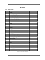
10
Tables
10.1
10.2
Unit Codes ....................................................................................................................... 59
Unit Conversion .............................................................................................................. 60
59
10.2.1 Pressure Units ................................................................................................................ 60
10.2.2 Temperature Units ......................................................................................................... 60
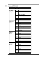
10.3
Command 220 details ..................................................................................................... 61
11
Performance
11.1
11.2
11.3
11.4
11.5
11.6
11.7
11.8
11.9
11.10
11.11
Sampling Rates ............................................................................................................... 63
Power-Up ......................................................................................................................... 63
Device Reset .................................................................................................................... 63
Self Test ........................................................................................................................... 63
Command Response Times ........................................................................................... 64
Busy and Delayed-Response......................................................................................... 64
Long Messages ............................................................................................................... 64
Non-Volatile Memory ...................................................................................................... 65
Modes ............................................................................................................................... 65
Write Protection .............................................................................................................. 65
Damping ........................................................................................................................... 65
63
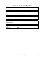
Annex A. Capability Checklist
66
Annex B. Default Configuration
67
Annex C. Revision History
72
Revision 1.0
HART® 7.x Field Device Specification
Page vii
List of Figures
Figure 1 Typical Communication Interface ................................................................... 4
Figure 2 Transmitter Operating Ranges........................................................................ 7
Figure 3 Transmitter 3-Screw Terminal Board and Grounding Screw ....................... 7
Figure 4 Three-Button Option ........................................................................................ 9
Figure 5 Locating the Failsafe Jumper ...................................................................... 10
List of Tables
Table 1 Abbreviations and Definitions .......................................................................... 1
Table 2 Device Identification .......................................................................................... 2
Table 3 Process Connections ........................................................................................ 6
Table 4 Analog Output Values ....................................................................................... 8
Table 5 Available Display Characteristics .................................................................. 11
Table 6 List of Dynamic Variables ............................................................................... 12
Table 7 Field Device Status .......................................................................................... 13
Table 8 Extended Device Status .................................................................................. 14
Table 9 Additional Field Device Status ....................................................................... 14
Table 10 Universal Commands .................................................................................... 16
Table 11 Common Practice Commands ...................................................................... 18
Table 12 Device Specific Commands .......................................................................... 19
Table 13 Unit Codes supported ................................................................................... 59
Table 14 Common Unit Conversions........................................................................... 60
Table 15 Temperature Units ......................................................................................... 60
Table 16 Command 220 details .................................................................................... 62
Table 17 Sampling Rates .............................................................................................. 63
Table 18 Response Times ............................................................................................ 64
Table 19 Capability checklist ....................................................................................... 66
Table 20 Default Configuration .................................................................................... 67
Page viii
HART® 7.x Field Device Specification
Revision 1.0
1 Introduction
1.1 Scope
The Honeywell Smart Pressure Transmitter, ST 700, device complies with HART Protocol
Revision 7.x . This document specifies all the device specific features and gives HART Protocol
implementation details. The functionality of this Field Device is described sufficiently to allow
its proper application in a process and its complete support in HART capable Host Applications.
1.2 Purpose
This specification is designed to complement other documentation by providing a complete,
unambiguous description of this Field Device from a HART Communication perspective.
1.3 Who should use this document?
The specification is designed to be a technical reference for HART capable Host Application
Developers, System Integrators and knowledgeable End Users. It also provides functional
specifications (e.g., commands, enumerations and performance requirements) used during Field
Device development, maintenance and testing. This document assumes the reader is familiar
with HART Protocol requirements and terminology.
1.4 Abbreviations and definitions
Table 1 Abbreviations and Definitions
ADC
Analog to Digital Converter
DAC
Digital to Analog Converter
EEPROM
Electrically-Erasable Programmable Read-Only Memory
ROM
Read-Only Memory
PV
Primary Variable
SV
Secondary Variable
TV
Tertiary Variable
MSG
Model Selection Guide
Float
An IEEE 754 single precision floating point value (4 bytes)
Packed
A string consisting of 6-bit alpha-numeric characters that are a subset of the ASCII
character set. This allows four characters to be packed into three bytes.
Unsigned-nn
An unsigned integer where nn indicates the number of bits in this integer. Multi-byte
integers are transmitted MSB-LSB.
Enum
It can be assigned any of the enumerators as a value
Revision 1.0
HART® 7.x Field Device Specification
Page 1
1.5 References
HART Field Communications Protocol Specification. HCF_SPEC-12, Revision 7.4, dated 29
June 2012.
ST_700_ HART_DE_34-ST-25-47_13Dec12_review: Document under review.
2 Device Identification
Table 2 Device Identification
Manufacturer Name:
Honeywell
Model Name(s):
ST700
Manufacture ID Code:
23
Device Type Code:
33
HART Protocol Revision
7.x
Device Revision:
1
Number of Device Variables
3
Physical Layers Supported
FSK
Physical Device Category
Transmitter, Non-DC-isolated Bus Device
(17 Hex)
(21 Hex)
The Honeywell ST 700 is designed to meet hazardous area approvals.
Refer to the user manual on the available methods of protections for use in hazardous locations.
Page 2
HART® 7.x Field Device Specification
Revision 1.0
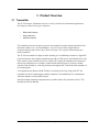
3 Product Overview
3.1 Transmitter
The ST 700 Pressure Transmitter comes in a variety of models for measurement applications
involving one of these basic types of pressure:
•
Differential Pressure
•
Gauge Pressure
•
Absolute Pressure
The transmitter measures the process pressure and transmits an output signal proportional to the
measured variable over a 4 to 20 milliampere, two-wire loop. Its major components are
electronics housing and a meter body as shown in Figure 1 for a typical differential pressure
model transmitter.
The ST 700 can transmit its output in either an analog 4 to 20 milliampere format or a digital DE
protocol format for direct digital communications with our TPS system, Allen-Bradley PLCs and
other control systems. Besides the process variable (PV) output, the transmitter also provides its
meter body temperature as a secondary variable and the Static Pressure as a tertiary variable,
which are both available as read-only parameters through the MC Toolkit when the transmitter is
in its analog mode.
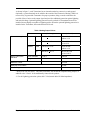
A configuration tool (Honeywell MCToolkit) is connected to the loop wiring of the ST 700
transmitter for direct communication with the transmitter. The handheld device communicates
with the transmitter via the HART interface.
Note that multiple mounting configurations are possible and are fully described in the ST 700
Installation and User Manuals.
Revision 1.0
HART® 7.x Field Device Specification
Page 3
Figure 1 Typical Communication Interface
Page 4
HART® 7.x Field Device Specification
Revision 1.0
3.2 Communicator Purpose
The communicator allows the user to adjust transmitter values, or diagnose potential problems
from a remote location such as the control room. The communicator can be used to:
•
Configure: Define and enter the transmitter’s operating parameters.
•
Monitor: Read the input pressure to the transmitter in engineering units and the
transmitter’s output in mA or percent.
•
Display: Retrieve and display data from the transmitter or the communicator’s memory.
•
Change Mode of Operation: Select configuration for multi-drop mode (digital) or loop
current enabled (analog) operation.
•
Check current output: Use the transmitter to supply the output current desired for
verifying analog loop operation, troubleshooting, or calibrating other components in the
analog loop.
•
Troubleshoot: Check status of transmitter operation and display diagnostic messages to
identify transmitter, communication, or operator error problems.
•
Product Interfaces
•
Process Interface
Revision 1.0
HART® 7.x Field Device Specification
Page 5
4 Product Interfaces
4.1 Process Interface
4.1.1
Sensor Input Channel
The primary variable is the pressure measured by the pressure sensor. Pressure Sensors are
housed in the meter body of the transmitter. The transmitter is piped to the process where the
pressure is to be measured using a mechanical connection. Please refer to the User Manual for
details on mounting and piping the transmitter to the process.
An additional internal sensor measures the meter body temperature that is provided to the user as
the secondary variable and Static Pressure is available as the tertiary variable.
4.1.2
Process Connections
Table 3 Process Connections
Transmitter Type
Process Connection
Differential
Pressure
• Process heads with ¼ -inch NPT female connection.
• Flange adapters and manifolds with 1/2-inch female connection are optional.
• Models with pseudo flange on one side include 2- or 3-inch ANSI class 150 flange.
Gauge Pressure
• Process head with ½ -inch NPT female connection.
• In-line ½ -inch NPT female connection (STG7xL).
• In-line ½ inch NPT male
• 9/16 AMINCO
• DIN 19213
• Process heads with ¼ -inch NPT female connection (STG7x4).
• Flange adapters and manifolds with 1/2-inch female connections are optional
(STG7x4).
• 2-inch Sanitary Tri-Clamp (STG7xT)
• Flush mount in 1-inch weld sleeve, with O-ring and locking bolt (STG7xP).
Absolute Pressure
• Process head with ½ -inch NPT female connection. (STA722, 740).
• In-line ½ inch NPT Female
• In-line ½ inch NPT male
• 9/16 AMINCO
• DIN 19213
Flange Mounted
Liquid Level
• Small flange ½ -inch, 1-, 1 ½ - and 2-inch (STF7xT)
• 2, 3- or 4-inch flange with flush or 2-, 4- or 6-inch extended diaphragm (See Table
14) on high pressure side.*
• DN 50, 80, or 100 PN 40 flange with flush or 2, 4 or 6 inch extended diaphragm
(See Table 14) on High Pressure Side*.
Remote Diaphragm
Seals
See Model Selection Guide for description of available Flanged, Threaded, Chemical
Tee, Saddle, and Sanitary process connections.
* Reference side has standard differential pressure process head.
Page 6
HART® 7.x Field Device Specification
Revision 1.0
4.2 Host Interface
The transmitter is designed to operate in a two-wire power/current loop with loop resistance and
power supply voltage within the operating range shown in figure 2.
1440
1200
Loop
Resistance
(ohms)
= Operating
Area
NOTE: A minimum of
250 0hms of loop
resistance is
necessary to support
communications. Loop
resistance equals
barrier resistance plus
wire resistance plus
receiver resistance.
Also 45 volt operation
is permitted if not an
intrinsically safe
installation.
800
650
450
250
0
10.8
16.28 20.63 25 28.3
37.0
42.4
Operating Voltage (Vdc)
21012
Figure 2 Transmitter Operating Ranges
Loop wiring is connected to the transmitter by simply attaching the positive (+) and negative (–)
loop wires to the positive (+) and negative (–) terminals on the Transmitter terminal block in the
Electronics Housing shown earlier in figure..
Figure 3 Transmitter 3-Screw Terminal Board and Grounding Screw
Revision 1.0
HART® 7.x Field Device Specification
Page 7
As shown in figure 3, each Transmitter has an internal terminal to connect it to earth ground.
Optionally, a ground terminal can be added to the outside of the Electronics Housing. While it is
not necessary to ground the Transmitter for proper operation, doing so tends to minimize the
possible effects of noise on the output signal and provides additional protection against lightning
and static discharge. Optional lightning protection can be ordered for Transmitters that will be
installed in areas highly susceptible to lightning strikes. When the optional lightning protection is
installed in the Transmitter, the terminal block will be red.
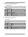
Table 4 Analog Output Values
Direction
Linear over-range*
Values (% of range)
Values (mA or V)
Down
-1.25 % + 0.1 %
3.8 to 4.0 mA
0.95 to 1.0 V
Up
105.0 % + 0.1 %
20.0 to 20.8 mA
5.0 to 5.2 V
Down
-1.25 % to + 0.1 %
3.8 to 4.0 mA
0.95 to 1.0 V
Up
103.125 % + 0.1 %
20.0 to 20.5 mA
5.0 to 5.125 V
Down: less than
- 1.25 %
3.58 mA
Up: greater than
+ 105 %
21 mA
Classic
NAMUR
Device malfunction
indication
Maximum current
21.8 mA
Multi-Drop current draw
4.0 mA
Lift-off voltage **
10.8 V
* Honeywell will offer the ST 700 HART transmitter with NAMUR compliant analog outputs, in
addition to the "Classic" levels traditionally featured in the product.
** For the Lightning protection option, add 1 Volt (internal added 50 Ohm impedance).
Page 8
HART® 7.x Field Device Specification
Revision 1.0
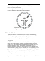
4.3 Local Interfaces, Jumpers and Switches
The ST 700 three-button option provides a user interface and operation without the use of the MC
Toolkit. Figure shows the location of the three-button option and the labels for each button.
Figure 4 Three-Button Option
The functions of the three buttons are:
Enter (S )
Enter the top level main menu from the normal PV display mode
Select a target to go down to the next menu level, up to the previous level or exit back to the PV
display mode
Accept the current value of an entered parameter
Down (↓)
Advance to the next configured screen when in the normal PV display mode
Scroll down to the next item in a menu
Advance through a list of parameters for configuration
Advance through numerical values or alpha characters for data entry
Up ( Z↑)
Revision 1.0
HART® 7.x Field Device Specification
Page 9
Go back to the previous configured screen when in the normal PV display mode
Scroll up to the previous item in a menu
Go back through a list of parameters for configuration
Go back through numerical values or alpha characters for data entry
Figure 5 Locating the Failsafe Jumper
4.3.1
Device Malfunction
The direction of indication of a detected malfunction by the analog current output is userselectable to up or down, by means of a two-position jumper inside the instrument. ST 700
transmitters are shipped with a default failsafe direction of upscale. This means that the
transmitter’s output will be driven upscale (maximum output) when the transmitter detects a
critical status.
Write Protection
The ST 700 transmitters have a transmitter security option, also known as a “write protect
option,” which is jumper-selectable. The jumper, located on the transmitter’s printed wiring
assembly (PWA), can be positioned to allow read and write access or read only access to the
transmitter’s configuration database. When the jumper is in the read only position, the
transmitter’s configuration and calibration data can only be read / viewed. The factory-default
jumper positions are for read and write access. The figure above shows the location of the write
protect jumper on the PWA. The Write Protect hardware Jumper is placed behind the Display
PWA. For accessing the hardware write protect jumper, the Display PWA needs to be removed.
Also a Software write protect is available. Refer Common Practice command 175 &command
176. When the Device is in Hardware write protect (Jumper) then the software write protect
functionality is inoperative.
Page 10
HART® 7.x Field Device Specification
Revision 1.0
4.4 Meter Display Options
The ST 700 Pressure Transmitter offers two display options: Basic and Advanced; see Table 5.
Table 5 Available Display Characteristics
Basic Display
•
Suitable for basic process needs
•
360o rotation in 90o Increments
•
2 lines, 16 characters
•
Standard units-of-measurement: Pa, KPa, MPa, KGcm2, TORR, ATM,
inH2O, mH2O, bar, mbar, inHg, FTH2O, mmH2O, MMHG, and PSI
•
Diagnostic messaging
•
Square root indication & Out-of-range indication
•
Supports optional 3-Button configuration
.
Revision 1.0
HART® 7.x Field Device Specification
Page 11
5 Dynamic Variables
Three Dynamic Variables are implemented.
Table 6 List of Dynamic Variables
Process
Variable
Meaning
Units
PV
Pressure
InH2O, psi, Pa, inH2O @ 4degC,
InHg, bar, kPa, mmH2O @ 4degC,
ftH2O, mbar, torr, inH2O @ 60degF,
mmH2O, g/Sqcm, atm, mmHg, Kg./Sqcm, Mpa
SV
Meter Body Temperature
Deg C, deg F, Rankine, Kelvin
TV
Static Pressure
Psi
The HART units’ code for inH2O@60degF is 145 as well as 240.
Page 12
HART® 7.x Field Device Specification
Revision 1.0
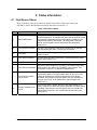
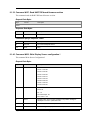
6 Status Information
6.1 Field Device Status
Many of the flags in the device status are further described by critical, non-critical, and
informative flags in the additional status bytes described in section 6.2.1.
Table 7 Field Device Status
Bit
Name
Use
7
Device Malfunction
This flag is set to "1" when any critical failure is detected. When a
"Device Malfunction" is indicated, the "More Status Available" status
flag is always asserted and further information is available in the
manufacturer specific status bytes. The designation for critical
status, and Honeywell's unique status bytes are described in
section 6.2.1.
6
Configuration Changed
Set when any parameter in the device configuration is changed.
The flag will be reset when command 38 is received.
5
Cold Start
Set when power is first applied. The flag will also be set when the
device is reset.
4
More Status Available
Set whenever any failure is detected. Command #48 gives further
detail. (See section 6.2.1).
3
Loop Current Fixed
Set when the device is placed in fixed current mode (command 40).
2
Loop Current Saturated
Set if the primary variable is out of range. The measurement limits
differ between the "classic" and "NAMUR" output options. This
event does not set bit 7 ("Field Device Malfunction").
Non-Primary Variable
Out Of Limits
Set if the temperature calculated from the internal meter body
temperature sensor is too high (greater than 125 deg C for most
transmitters). When this status is asserted, the "More Status
Available" flag is also set, and the specific failure is indicated as
"Sensor Over Temp" in the manufacturer specific status (see
section 6.2.1).
Primary Variable Out of
Limits
Set if the pressure is greater than twice the Upper Range Limit
(URL) of the device. When this status is asserted, the "More Status
Available" flag is also set, and the specific failure is indicated as
"Meter Body Overload" in the manufacturer specific status (see
section 6.2.1).
1
0
Revision 1.0
HART® 7.x Field Device Specification
Page 13
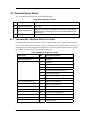
6.2 Extended Device Status
The Extended Device Status byte has the following flags:
Table 8 Extended Device Status
6.2.1
Bit
Description
Use in Device
0
Maintenance Required
Not Used
1
Device Variable Alert
Set when a critical or non-critical error (except “In Fixed Output
Current Mode”) associated with the PV has been detected (see
section 6.2.1).
2-7
Undefined
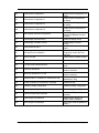
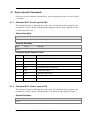
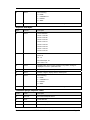
Command #48 – Additional Field Device Status
Command #48 returns 8 bytes of data. The first 3 bytes contain device specific status as shown
below. The Extended Device Status byte (byte 6) will be returned as defined above in section 6.2.
All other bytes are unused, and will be returned as 0. The three detailed status bytes are divided
by category of status: critical error and non-critical error.
Table 9 Additional Field Device Status
Status Type
Bit
Command 48 Status
Critical status (Byte 1)
7
Unused
6
Unused
5
Sensor Comm Timeout
4
Meter Body Critical Failure
3
Electronic Module Diag Failure
2
Config Data Corrupt
1
Meter Body NVM Corrupt
0
Electronic Module DAC Failure
7
No DAC Compensation
6
No Factory Calibration
5
PV Out of Range
4
Fixed Current Mode
3
Sensor Over Temperature
2
Meter Body Excess Correct
1
Electronic Module Comm Failure
0
Display Failure
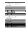
Non critical status (Byte 2)
Page 14
HART® 7.x Field Device Specification
Revision 1.0
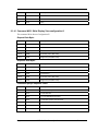
Non critical status 2 (Byte 3)
7
Low Supply Voltage
6
No DAC Calibration
5
Tamper Alarm
4
Meter Body Unreliable Comm
3
Loop current noise
2
AO Out of Range
1
URV Set Error - Span Config Button
0
LRV Set Error - Zero Config Button
All critical faults will be indicated to the user with bits 4 and 7 set in the Field Device Status byte
of the response.
Some faults are cleared when the error condition is resolved, while All Critical Status faults
require the device be power cycled.
Revision 1.0
HART® 7.x Field Device Specification
Page 15
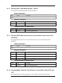
7 Universal Commands
The transmitter supports version 7.x of the HART protocol, thus each universal command is as
specified in that standard. The following universal commands are provided by the device:
Table 10 Universal Commands
Number
Name
Notes
0
Read Unique Identifier
Returns unique identification for the device
1
Read Primary Variable
Returns PV value and its unit
2
Read Loop Current and Percent of
Range
Returns AO value and % range
3
Read Dynamic Variables and Loop
Current
Returns PV and SV values and
corresponding unit values along with AO
value
6
Write Polling Address
Changes device’s polling address and loop
current mode.
7
Read Loop Configuration
Returns polling address and loop current
mode status.
8
Read Dynamic Variable Classifications
Returns dynamic variable classification.
9
Read Device Variables with Status
Returns dynamic variables PV, SV & TV with
status.
11
Read Unique Identifier Associated
With Tag
Same response as command 0
12
Read Message
Returns 24 bytes of packed ASCII data
13
Read Tag, Descriptor, Date
Returns tag, descriptor (packed ASCII
format) and date from the device
14
Read Primary Variable Transducer
Information
Returns transducer limits and span
15
Read Device Information
Returns burnout settings, PV unit value, LRV,
URV, damping value and write protect code
16
Read Final Assembly Number
Returns final assembly number
17
Write Message
Write 24 bytes of packed ASCII data.
18
Write Tag, Descriptor, Date
Writes tag, descriptor (packed ASCII format)
and date to the device
19
Write Final Assembly Number
Writes final assembly number to the device
20
Read Long Tag
Returns 32-byte Long Tag.
21
Read Unique Identifier
Returns unique identifier associated with
Long Tag.
Page 16
HART® 7.x Field Device Specification
Revision 1.0
Number
Name
Notes
22
Write Long Tag
Writes Long Tag
38
Reset Configuration Changed Flag
Resets the configuration change flag
48
Read Additional Device Status
See section 11.2 for details.
Revision 1.0
HART® 7.x Field Device Specification
Page 17
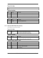
8 Common-Practice Commands
8.1 Supported Common Practice Commands
The following common-practice commands are implemented:
Table 11 Common Practice Commands
Number
Name
Notes
33
Read Device Variables
Will return Device Variable 0 = PV (Pressure), Device
Variable 1 = SV (Meter body Temperature) and Device
Variable 2= TV (Static Pressure) when requested.
34
Write PV Damping Value
Accepts damping values between 0 and 32 seconds.
35
Write PV Range Values
Write PV LRV/URV values
36
Set PV Upper Range Value
Set current PV as URV. Adjusts the span accordingly.
Some ST 700 models support accurate operation in
both the forward and reverse directions. Consult the
Model Selection Guide for models that are compound
characterized.
37
Set PV Lower Range Value
Set current PV as LRV. Adjusts the span accordingly.
40
Enter/Exit Fixed Current Mode
Sets loop current to a fixed value.
42
Perform Device Reset
Resets the device
43
Set Primary Variable Zero
Sets present PV to zero
44
Write Primary Variable Units
Write PV units value
45
Trim Loop Current Zero
Trims loop current to 4mA
46
Trim Loop Current Gain
Trims loop current to 20mA
47
Write PV Transfer Function
Writes Transfer Function as Linear and Square root.
53
Write Device Variable Units
Writes Device Variable Units
71
Lock Device
This command locks a device preventing any changes
being made from a local panel or from another master.
76
Read Lock Device status
This command reads the current state of lock device.
8.2 Burst Mode
This Field Device does not support Catch Device Variable.
8.3 Catch Device Variable
This Field Device does not support Catch Device Variable.
Page 18
HART® 7.x Field Device Specification
Revision 1.0
9 Device-Specific Commands
The following device-specific commands are implemented:
Table 12 Device Specific Commands
Number
Name
Notes
130
Write Upper Sensor Trim Point (Correct URV)
It trims the PV to URV.
131
Write Lower Sensor Trim Point (Correct LRV)
It trims the PV to LRV.
133
Reset Corrects
It resets all the user correct
operations performed.
134
Read transmitter specifics
13 digit Meter-body bar code and
display information
138
Read Primary Variable Sensor Information
Reads LRV and URV
139
Read model number – Key Number and Table I
Reads 7 byte Key number, and
Table I information. For factory
use.
140
Read model number - Table II
Reads Table II information. For
factory use.
141
Read model number - Table III
Reads Table III information. For
factory use.
142
Read time in service, service life remaining, percent
time in stress
Read last time and date for correct URV, correct
LRV and zero trim.
It reads Time in Service, Service
life and % life in stress.
Reads Calibration records.
145
Read filter selection
Reads filter parameters.
146
Write filter selection
Write filter parameters.
148
Read power fail counter and its timestamp
The power fail count and Time
stamp are read.
149
Read Electronics Temperature and upper tracking
parameters value
Electronics Temperature
maximum tracking parameters.
150
Read Electronics Temperature lower tracking
parameters value
Electronics Temperature
minimum tracking parameters.
151
Read differential PV UP tracking parameters
Reads PV maximum tracking.
152
Read Meter Body Temperature upper tracking
parameters
Reads Meter Body Temperature
tracking (maximum)
153
Read Meter Body Temperature lower tracking
parameters
Reads Meter Body Temperature
tracking (minumum)
154
Read Static Pressure and its tracking parameters
Reads Static Pressure tracking
155
Read current and min operating voltage and its
timestamp
Reads operating voltage and
minimum Time stamp.
144
Revision 1.0
HART® 7.x Field Device Specification
Page 19
156
Reset min terminal voltage and its time stamp
It resets the Operating Voltage
records.
157
Read M360 core temperature up tracking
parameters
Reads M360 temp up tracking.
158
Read M360 core temperature down tracking
parameters
Reads M360 temp down
tracking.
159
Read AVDD max and time stamp
Read AVDD records and Time
stamp.
160
Read AVDD min and time stamp
Read AVDD records and Time
stamp.
161
Read sensor install date and time in service
Reads sensor installed date.
162
Read MB stress monitor and MB service life
163
Write install date to sensor
Reads MB Stress and service
life.
Writes Sensor install date. One
time writable.
164
Read Model Number –Table IV
Reads Table IV information. For
factory use.
165
Read Previous time and date for correct URV,
correct LRV, zero trim
Reads Calibration records.
166
Read current time and date for correct URV, correct
LRV, zero trim
Reads Calibration records.
167
Read current, last and previous reset correct Time &
Date
Reads Calibration records for
Reset corrects.
168
Read differential PV Down tracking parameters
Reads PV down tracking.
175
Read/Lock Write Protect Configuration
Soft Write protection
176
Write/Change Write Protect Password
Changes the write Protect
Password.
177
Read Database ID
Reads Database ID for the
requested config history code
178
Read last 5 Configuration history
Enables to view the last 5
configuration history.
185
Read low flow cutoff mode
Reads Method selected for Low
Flow cut-off.
186
Read sensor time in service
Reads Sensor time in Service.
187
Read f/w revision
It reads Communication board
firmware rev. number.
202
Write Screen configuration I
Writes Screen Configuration I for
display
203
Write Screen configuration II
Writes Screen Configuration II
for display
204
Write Screen configuration III
Writes Screen Configuration III
for display
205
Write Screen configuration IV
Writes Screen Configuration IV
for display
Page 20
HART® 7.x Field Device Specification
Revision 1.0
206
Read Screen configuration I
Reads Screen Configuration I for
display
207
Read Screen configuration II
Reads Screen Configuration II
for display
208
Read Screen configuration III
Reads Screen Configuration III
for display
209
Read Screen configuration IV
Reads Screen Configuration IV
for display
210
Write Display Common Configuration
211
Read Display Common Setup
212
Read Display Firmware Version
220
Read additional status
221
Set Date/Time for calibration
Before Calibration it is
compulsory to enter the Time
and Date.
222
Sensor f/w read
Reads Sensor Firmware version
223
Read flow value
Read the % flow value.
225
Low flow cutoff method selection
226
Read user breakpoint
Selects the method for Low flow
cutoff.
It reads the user break point for
method 1 selected.
227
Write user breakpoint in % flow
It writes the user break point for
method 1 selected.
228
Read the state of “Available for maintenance” flag
Reads the status of “Available for
Maintenance” Flag
229
Enable “Available for maintenance” message
Enables the flag.
230
Read the Tamper configuration
Reads the tamper configuration
231
Write tamper configuration
Writes the tamper configuration.
232
Reset recorded tamper attempts
It resets the Tamper attempts
recorded.
245
Read Output level Selection
Reads whether device is in
Classic mode or NAMUR?
246
Write Output level Selection
Write output mode as NAMUR or
Classic.
Revision 1.0
HART® 7.x Field Device Specification
Writes Displays common
features like Rotation time and
Contrast.
Reads the display set-up.
Reads Display Firmware
Version.
It reads the Device status in
Detail.
Page 21
9.1 Device Specific Commands
Each device specific command is detailed below. Only the supported response codes are listed for
a command.
9.1.1
Command #130: Correct Input to URV
This command performs a calibration trim for the sensor. The calibration pressure applied to the
transmitter is received with this command and the transmitter trims the sensor calibration so that
its output equals this value.
Request Data Bytes
Byte
Format
Description
None
Response Data Bytes
Byte
Format
Description
None
Command-Specific Response Codes
9.1.2
Code
Class
Description
0
Success
No Command-Specific Errors
3
Error
Passed parameter too large
4
Error
Passed parameter too small
6
Error
Transmitter specific command error
7
Error
In Write Protect Mode
9
Error
Applied Process too High
10
Error
Applied process too low
32
Error
Busy
Command #131: Correct input at LRV
This command performs a calibration trim for the sensor. The calibration pressure applied to the
transmitter is received with this command and the PV is calibrated to the applied URV input.
Request Data Bytes
Byte
Format
Description
None
Page 22
HART® 7.x Field Device Specification
Revision 1.0
Response Data Bytes
Byte
Format
Description
None
Command-Specific Response Codes
9.1.3
Code
Class
Description
0
Success
No Command-Specific Errors
3
Error
Passed parameter too large
4
Error
Passed parameter too small
6
Error
Transmitter specific command error
7
Error
In Write Protect Mode
9
Error
Applied Process too High
10
Error
Applied process too low
32
Error
Busy
Command #133: Reset Corrects
This command removes the calibration and returns the performance to factory calibration. This
function is useful as a diagnostic tool to get an indication of characterization performance, as well
as the PV is calibrated to the applied LRV input.
Request Data Bytes
Byte
Format
Description
None
Response Data Bytes
Byte
Format
Description
None
Command-Specific Response Codes
Code
Class
Description
0
Success
No Command-Specific Errors
6
Error
Transmitter specific command error
7
Error
In Write Protect Mode
32
Error
Busy
Revision 1.0
HART® 7.x Field Device Specification
Page 23
9.1.4
Command #134: Read Transmitter Specifics
The command reads the 13 digit Meter-body bar code and display information.
Request Data Bytes
Byte
Format
Description
None
Response Data Bytes
Byte
Format
Description
0
Enum
Device type
1-13
ASCII
Meter-body bar code
14
Enum
meter connected flag
00: Not Connected
01: Connected
15
Enum
meter type
01: Advanced display
02: Basic display
Command-Specific Response Codes
9.1.5
Code
Class
Description
0
Success
No Command-Specific Errors
Command #138: Read Primary Variable Sensor Information
This command reads the PV related information for sensor.
Request Data Bytes
Byte
Format
Description
None
Response Data Bytes
Byte
Format
Description
0
Enum
Sensor Limits/Min Span Units
1-4
IEEE Float
Upper Range Limit
5-9
IEEE Float
Lower Range Limit
Command-Specific Response Codes
Code
Class
Description
0
Success
No Command-Specific Errors
Page 24
HART® 7.x Field Device Specification
Revision 1.0
9.1.6
Command #139: Read Model Number – Key Number, Table I
This command reads the 7 byte key number and 20 byte Table 1 information.
Request Data Bytes
Byte
Format
Description
None
Response Data Bytes
Byte
Format
Description
0-6
Enum
key number
7-27
Enum
Table 1 information
Command-Specific Response Codes
9.1.7
Code
Class
Description
0
Success
No Command-Specific Errors
Command #140: Read Model Number – Table II
This command reads Model number Table II information.
Request Data Bytes
Byte
Format
Description
None
Response Data Bytes
Byte
Format
Description
0-19
Enum
Table II information
Command-Specific Response Codes
Code
Class
Description
0
Success
No Command-Specific Errors
Revision 1.0
HART® 7.x Field Device Specification
Page 25
9.1.8
Command #141: Read Model Number –Table III
This command reads Model number Table III information.
Request Data Bytes
Byte
Format
Description
None
Response Data Bytes
Byte
Format
Description
0-19
Enum
Table III information
Command-Specific Response Codes
9.1.9
Code
Class
Description
0
Success
No Command-Specific Errors
Command #142: Read time in service, percent time in stress, service life
remaining
This command reads time in service, percent time in stress, service life remaining for the
transmitter.
Request Data Bytes
Byte
Format
Description
None
Response Data Bytes
Byte
Format
Description
0-3
Enum
Time in Service
4-7
Float
Percent Time in stress
8-11
Enum
Service Life remaining
Command-Specific Response Codes
Code
Class
Description
0
Success
No Command-Specific Errors
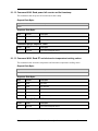
9.1.10 Command #144: Read last Time & Date for correct URV, correct LRV, zero
trim
This command reads Last Time and Dates for correct URV, correct LRV and zero trim.
Page 26
HART® 7.x Field Device Specification
Revision 1.0
Request Data Bytes
Byte
Format
Description
None
Response Data Bytes
Byte
Format
Description
0-4
Enum
last correct URV time (DD 1 MM 1 YY 1 HR 1 MIN 1)
5-9
Enum
last correct LRV time (DD 1 MM 1 YY 1 HR 1 MIN 1)
10-14
Enum
last zero trim time (DD 1 MM 1 YY 1 HR 1 MIN 1)
Command-Specific Response Codes
Code
Class
Description
0
Success
No Command-Specific Errors
6
Error
Transmitter specific command error
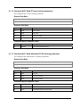
9.1.11 Command #146: Write filter selection
This command writes the filter selection.
Request Data Bytes
Byte
Format
0
Enum
Description
0x00 selects the optimal 50/60 Hz noise filter.
0x01 selects the fastest speed of response filter.
Response Data Bytes
Byte
Format
0
Enum
Description
0x00 selects the optimal 50/60 Hz noise filter.
0x01 selects the fastest speed of response filter.
Command-Specific Response Codes
Code
Class
Description
0
Success
No Command-Specific Errors
5
Error
Too Few Data Bytes Received
7
Error
Transmitter In Write Protect Mode
16
Error
Access Denied
Revision 1.0
HART® 7.x Field Device Specification
Page 27
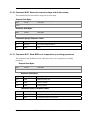
9.1.12 Command #148: Read power fail counter and its timestamp
This command reads the power fail counter and its time stamp.
Request Data Bytes
Byte
Format
Description
None
Response Data Bytes
Byte
Format
Description
0-1
Enum
Power fail count
2-5
Enum
Time stamp
Command-Specific Response Codes
Code
Class
Description
0
Success
No Command-Specific Errors
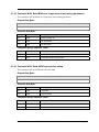
9.1.13 Command #149: Read ET and electronics temperature tracking values.
This command reads electronics temperature and electronics temperature tracking values.
Request Data Bytes
Byte
Format
Description
None
Response Data Bytes
Byte
Format
Description
0-3
Float
ET value
4-7
Float
ET max limit
8-11
Float
max value
12-15
Float
max time counter
16-19
Float
max time stamp
Command-Specific Response Codes
Code
Class
Description
0
Success
No Command-Specific Errors
Page 28
HART® 7.x Field Device Specification
Revision 1.0
9.1.14 Command #150: Read ET lower tracking parameters
This command reads ET lower tracking parameters.
Request Data Bytes
Byte
Format
Description
None
Response Data Bytes
Byte
Format
Description
0-3
Float
ET min limit
4-7
Float
min value
8-11
Float
min time counter
12-15
Float
min time stamp
Command-Specific Response Codes
Code
Class
Description
0
Success
No Command-Specific Errors
9.1.15 Command #151: Read differential PV UP tracking parameters
This command reads differential PV UP tracking parameters.
Request Data Bytes
Byte
Format
Description
None
Response Data Bytes
Byte
Format
Description
0-3
Float
PV max
4-7
Float
PV up accumulator
7-11
Float
PV up time stamp
Command-Specific Response Codes
Code
Class
Description
0
Success
No Command-Specific Errors
6
Error
Transmitter specific command error
Revision 1.0
HART® 7.x Field Device Specification
Page 29
9.1.16 Command #152: Read MBT upper tracking parameters
This command reads MBT upper tracking parameters.
Request Data Bytes
Byte
Format
Description
None
Response Data Bytes
Byte
Format
Description
0-3
Float
MBT max
4-7
Float
MBT max accumulator
8-11
Float
MBT max time stamp
Command-Specific Response Codes
Code
Class
Description
0
Success
No Command-Specific Errors
6
Error
Transmitter specific command error
9.1.17 Command #153: Read MBT lower tracking parameters
This command reads MBT lower tracking parameters.
Request Data Bytes
Byte
Format
Description
None
Response Data Bytes
Byte
Format
Description
0-3
Float
MBT min
4-7
Float
MBT min accumulator
8-11
Float
MBT min time stamp
Command-Specific Response Codes
Code
Class
Description
0
Success
No Command-Specific Errors
6
Error
Transmitter specific command error
Page 30
HART® 7.x Field Device Specification
Revision 1.0
9.1.18 Command #154: Read SP and its tracking parameters
This command reads SP and its tracking parameters.
Request Data Bytes
Byte
Format
Description
None
Response Data Bytes
Byte
Format
Description
0-3
Float
SP max
4-7
Float
SP max accumulator
8-11
Float
SP max time stamp
Command-Specific Response Codes
Code
Class
Description
0
Success
No Command-Specific Errors
6
Error
Transmitter specific command error
9.1.19 Command #155: Read current, minimum operating voltage and its
timestamp
This command reads current, minimum operating voltage and its timestamp.
Request Data Bytes
Byte
Format
Description
None
Response Data Bytes
Byte
Format
Description
0-3
Float
Vloop current value(4),
4-7
Float
VLOOP min value(4),
8-11
Float
Vloop min time stamp(4)
Command-Specific Response Codes
Code
Class
Description
0
Success
No Command-Specific Errors
Revision 1.0
HART® 7.x Field Device Specification
Page 31
9.1.20 Command #156: Reset min terminal voltage and its time stamp
This command Resets min terminal voltage and its time stamp.
Request Data Bytes
Byte
Format
Description
None
Response Data Bytes
Byte
Format
Description
None
Command-Specific Response Codes
Code
Class
Description
0
Success
No Command-Specific Errors
32
Error
Busy
9.1.21 Command #157: Read M360 core temperature up tracking parameters
This command reads the M360 (Sensor’s Microprocessor) core temperature up tracking
parameters.
Request Data Bytes
Byte
Format
Description
None
Response Data Bytes
Byte
Format
Description
0-3
Float
M360 core temp max
4-7
Float
max accumulator
7-11
Float
max time stamp
Command-Specific Response Codes
Code
Class
Description
0
Success
No Command-Specific Errors
6
Error
Transmitter specific command error
Page 32
HART® 7.x Field Device Specification
Revision 1.0
9.1.22 Command #158: Read M360 core temperature down tracking parameters
This command reads the M360 core temperature down tracking parameters.
Request Data Bytes
Byte
Format
Description
None
Response Data Bytes
Byte
Format
Description
0-3
Float
M360 core temp min
4-7
Float
min accumulator
7-11
Float
min time stamp
Command-Specific Response Codes
Code
Class
Description
0
Success
No Command-Specific Errors
6
Error
Transmitter specific command error
9.1.23 Command #159: Read AVDD max and time stamp
This command reads the AVDD max and time stamp.
Request Data Bytes
Byte
Format
Description
None
Response Data Bytes
Byte
Format
Description
0-3
Float
AVDD max
4-7
Float
max time stamp
Command-Specific Response Codes
Code
Class
Description
0
Success
No Command-Specific Errors
6
Error
Transmitter specific command error
Revision 1.0
HART® 7.x Field Device Specification
Page 33
9.1.24 Command #160: Read AVDD min and time stamp
This command reads the AVDD min and time stamp.
Request Data Bytes
Byte
Format
Description
None
Response Data Bytes
Byte
Format
Description
0-3
Float
AVDD min
4-7
Float
min time stamp
Command-Specific Response Codes
Code
Class
Description
0
Success
No Command-Specific Errors
6
Error
Transmitter specific command error
9.1.25 Command #161: Read sensor install date
This command reads the sensor install date.
Request Data Bytes
Byte
Format
Description
None
Response Data Bytes
Byte
Format
Description
0-4
Enum
install date
Command-Specific Response Codes
Code
Class
Description
0
Success
No Command-Specific Errors
6
Error
Transmitter specific command error
Page 34
HART® 7.x Field Device Specification
Revision 1.0
9.1.26 Command #162: Read MB stress monitor and MB service life
This command reads the MB stress monitor and MB service life.
Request Data Bytes
Byte
Format
Description
None
Response Data Bytes
Byte
Format
Description
0-3
Float
MB stress monitor
4-7
Float
service life
Command-Specific Response Codes
Code
Class
Description
0
Success
No Command-Specific Errors
6
Error
Transmitter specific command error
9.1.27 Command #163: Write install date to sensor
This command write install date to sensor.
Request Data Bytes
Byte
Format
Description
0
Enum
Date
1
Enum
Month
2
Enum
Year
Response Data Bytes
Byte
Format
Description
0
Enum
Date
1
Enum
Month
2
Enum
Year
3-4
Enum
Minutes
Command-Specific Response Codes
Code
Class
Description
0
Success
No Command-Specific Errors
5
Error
Too few data bytes received
7
Error
In write protect mode
Revision 1.0
HART® 7.x Field Device Specification
Page 35
Code
Class
Description
16
Error
Access Restricted
32
Error
Busy
9.1.28 Command #164: Read Model Number –Table IV
This command reads the 20 byte Model Number –Table IV
Request Data Bytes
Byte
Format
Description
None
Response Data Bytes
Byte
Format
Description
0-19
Enum
Model Number –Table IV Information
Command-Specific Response Codes
Code
Class
Description
0
Success
No Command-Specific Errors
9.1.29 Command #165: Read Previous Time & Date for correct URV, correct LRV,
zero trim
This command reads Previous Time and Dates for correct URV, correct LRV and zero trim.
Request Data Bytes
Byte
Format
Description
None
Response Data Bytes
Byte
Format
Description
0-4
Enum
Previous correct URV time (DD 1 MM 1 YY 1 HR 1 MIN 1)
5-9
Enum
Previous correct LRV time (DD 1 MM 1 YY 1 HR 1 MIN 1)
10-14
Enum
Previous zero trim time (DD 1 MM 1 YY 1 HR 1 MIN 1)
Command-Specific Response Codes
Code
Class
Description
0
Success
No Command-Specific Errors
6
Error
Transmitter specific command error
Page 36
HART® 7.x Field Device Specification
Revision 1.0
9.1.30 Command #166: Read current Time & Date for correct URV, correct LRV,
zero trim
This command reads Current Time and Dates for correct URV, correct LRV and zero trim.
Request Data Bytes
Byte
Format
Description
None
Response Data Bytes
Byte
Format
Description
0-4
Enum
Current correct URV time (DD 1 MM 1 YY 1 HR 1 MIN 1)
5-9
Enum
Current correct LRV time (DD 1 MM 1 YY 1 HR 1 MIN 1)
10-14
Enum
Current zero trim time (DD 1 MM 1 YY 1 HR 1 MIN 1)
Command-Specific Response Codes
Code
Class
Description
0
Success
No Command-Specific Errors
6
Error
Transmitter specific command error
9.1.31 Command #167: Read current, last and previous reset correct Time & Date
This command reads the current, last and previous reset correct T&D
Request Data Bytes
Byte
Format
Description
None
Response Data Bytes
Byte
Format
Description
0-4
Enum
Read current reset correct T&D( DD 1 MM 1 YY 1 HR 1 MIN 1)
5-9
Enum
Read last reset correct T&D( DD 1 MM 1 YY 1 HR 1 MIN 1)
10-14
Enum
Read previous reset correct T&D( DD 1 MM 1 YY 1 HR 1 MIN 1)
Command-Specific Response Codes
Code
Class
Description
0
Success
No Command-Specific Errors
6
Error
Transmitter specific command error
Revision 1.0
HART® 7.x Field Device Specification
Page 37
9.1.32 Command #168: Read differential PV Down tracking parameters
This command reads the differential PV Down tracking parameters.
Request Data Bytes
Byte
Format
Description
None
Response Data Bytes
Byte
Format
Description
0-3
Float
DP min
4-7
Float
DP min accumulator
8-11
Float
DP min time stamp
Command-Specific Response Codes
Code
Class
Description
0
Success
No Command-Specific Errors
6
Error
Transmitter specific command error
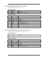
9.1.33 Command #175: Read/Lock Write Protect Configuration
This command Read/Lock Write Protect Configuration.
Request Data Bytes
Byte
Format
0
Enum
Description
0x01 - Enable WP
0x02 - Read WP status
Response Data Bytes
Byte
Format
0
Enum
Description
0x00 - Disabled
0x01 - Enabled
Command-Specific Response Codes
Code
Class
Description
0
Success
No Command-Specific Errors
2
Error
Invalid Selection
5
Error
Too Few Data Bytes Received
7
Error
Transmitter In Write Protect Mode
Page 38
HART® 7.x Field Device Specification
Revision 1.0
Code
Class
Description
16
Error
Access Denied
32
Error
Busy
9.1.34 Command #176: Write/Change Write Protect Password
This command Write/Change Write Protect Password.
Request Data Bytes
Byte
Format
Description
0
Enum
Unlock(0x00) / Change(0x03)
1-4
ASCII
Password
Response Data Bytes
Byte
Format
Description
0
Enum
Unlock(0x00) / Change(0x03)
Command-Specific Response Codes
Code
Class
Description
0
Success
No Command-Specific Errors
2
Error
Invalid Selection
5
Error
Too Few Data Bytes Received
6
Error
Transmitter specific command error
7
Error
Transmitter In Write Protect Mode
16
Error
Access Denied
32
Error
Busy
9.1.35 Command #177: Read Database ID
This command provides a Database ID for the requested configuration history code.
Request Data Bytes
Byte
Format
Description
0
Enum
01:-(This is request byte to read latest parameter)
02:- (This is request byte to read second last parameter written)
03:- (This is request byte to read third last parameter written)
04:- (This is request byte to read forth last parameter written)
05:- (This is request byte to read fifth last parameter written)
Revision 1.0
HART® 7.x Field Device Specification
Page 39
Response Data Bytes
Byte
Format
0
Enum
Description
Database ID of the parameter for which we have made request
When no record is present, database ID returned will be 0xFF.
Command-Specific Response Codes
Code
Class
Description
0
Success
No Command-Specific Errors
2
Error
Invalid Selection
5
Error
Too Few Data Bytes Received
9.1.36 Command #178: Read Configuration history
This command provides a history of the last 5 Configuration changes.
Request Data Bytes
Byte
Format
Description
0
Enum
01:-(This is request byte to read latest parameter)
02:- (This is request byte to read second last parameter written)
03:- (This is request byte to read third last parameter written)
04:- (This is request byte to read forth last parameter written)
05:- (This is request byte to read fifth last parameter written)
Response Data Bytes
Byte
Format
Description
0
Enum
Database ID of the parameter for which we have made request
When no record is present, database ID returned will be 0xFF.
1-33
Enum
Value of the parameter for which we have made request
We will get number of byte= size of parameter
Eg, If PV unit is of size 2 byte so we will get 2 byte rest 3-33 bytes will be
garbage.
Rest bytes will be garbage data
When no record is present, it will return 32 garbage bytes.
Command-Specific Response Codes
Code
Class
Description
0
Success
No Command-Specific Errors
2
Error
Invalid Selection
5
Error
Too Few Data Bytes Received
Page 40
HART® 7.x Field Device Specification
Revision 1.0
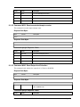
9.1.37 Command #185: Read low flow cutoff mode
This command reads low flow cutoff mode
Request Data Bytes
Byte
Format
Description
None
Response Data Bytes
Byte
Format
Description
0
Enum
0x00 – Method 1
0x01 – Method 2
Command-Specific Response Codes
Code
Class
Description
0
Success
No Command-Specific Errors
9.1.38 Command #186: Read sensor time in service
This command reads the Sensor Time in Service.
Request Data Bytes
Byte
Format
Description
None
Response Data Bytes
Byte
Format
Description
0-3
Float
Sensor Time in Service
Command-Specific Response Codes
Code
Class
Description
0
Success
No Command-Specific Errors
6
Error
Transmitter specific command error
Revision 1.0
HART® 7.x Field Device Specification
Page 41
9.1.39 Command #187: Read HART-DE board firmware revision
This command reads the HART-DE board firmware revision.
Request Data Bytes
Byte
Format
Description
None
Response Data Bytes
Byte
Format
0-7
ASCII
Description
Command-Specific Response Codes
Code
Class
Description
0
Success
No Command-Specific Errors
32
Error
Busy
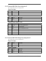
9.1.40 Command #202: Write Display Screen configuration I
This command Write Screen Configuration I.
Request Data Bytes
Byte
Format
0
Enum
Description
Screen Selection
screen 1:-Hex 3E
screen 2:-Hex 3F
screen 3:-Hex 40
screen 4:-Hex 41
screen 5:-Hex 42
screen 6:-Hex 43
screen 7:-Hex 44
screen 8:-Hex 45
1
Enum
Screen Format
None- 00
PV - 01
PV & Bar Graph - 02
PV & Trend -– 03
2
Enum
Identifies which of the process variables in the publish message is
displayed in the view – parameter index
3-4
Enum
Unit Code (Refer Table 11.1)
5
Enum
Number of digits to display after the decimal point.
Page 42
HART® 7.x Field Device Specification
Revision 1.0
6
Enum
PV Processing.
0 – NONE
1 – CONVERT EU.
2 – LINEAR
3 – SQRT
7
Trend duration
Duration of a trend screen in hours. Valid range 1 – 24
Response Data Bytes
Byte
Format
Description
0
Enum
Screen Selection
screen 1:-Hex 3E
screen 2:-Hex 3F
screen 3:-Hex 40
screen 4:-Hex 41
screen 5:-Hex 42
screen 6:-Hex 43
screen 7:-Hex 44
screen 8:-Hex 45
1
Enum
Screen Format
None- 00
PV - 01
PV & Bar Graph - 02
PV & Trend – 03
2
Enum
Identifies which of the process variables in the publish message is
displayed in the view – parameter index
3-4
Enum
Unit Code (Refer Table 11.1)
5
Enum
Number of digits to display after the decimal point.
6
Enum
PV Processing.
0 – NONE
1 – CONVERT EU.
2 – LINEAR
3 – SQRT
7
Trend duration
Duration of a trend screen in hours. Valid range 1 – 24
Command-Specific Response Codes
Code
Class
Description
0
Success
No Command-Specific Errors
2
Error
Invalid Selection
5
Error
Too Few Data Bytes Received
6
Error
Transmitter specific command error
Revision 1.0
HART® 7.x Field Device Specification
Page 43
Code
Class
Description
7
Error
Transmitter In Write Protect Mode
16
Error
Access Denied
32
Error
Busy
9.1.41 Command #203: Write Display View configuration II
This command Write Screen Configuration II.
Request Data Bytes
Byte
Format
Description
0
Enum
View OID
1-4
Float
fCustomEuHi
5-8
Float
fCustomEuLo
10-13
Float
fLowLimit (Trend, Bar chart)
14-17
Float
fHighLimit (Trend, Bar chart)
Response Data Bytes
Byte
Format
Description
0
Enum
View OID
1-4
Float
fCustomEuHi
5-8
Float
fCustomEuLo
10-13
Float
fLowLimit (Trend, Bar chart)
14-17
Float
fHighLimit (Trend, Bar chart)
Command-Specific Response Codes
Code
Class
Description
0
Success
No Command-Specific Errors
2
Error
Invalid Selection
5
Error
Too Few Data Bytes Received
6
Error
Transmitter specific command error
7
Error
Transmitter In Write Protect Mode
16
Error
Access Denied
32
Error
Busy
Page 44
HART® 7.x Field Device Specification
Revision 1.0
9.1.42 Command #204: Write View configuration III
This command Write Screen Configuration III.
Request Data Bytes
Byte
Format
Description
0
Enum
View OID
1-18
Float
CustomUnits
Response Data Bytes
Byte
Format
Description
0
Enum
View OID
1-18
Enum
CustomUnits
Command-Specific Response Codes
Code
Class
Description
0
Success
No Command-Specific Errors
2
Error
Invalid Selection
5
Error
Too Few Data Bytes Received
6
Error
Transmitter specific command error
7
Error
Transmitter In Write Protect Mode
16
Error
Access Denied
32
Error
Busy
9.1.43 Command #205: Write Display View configuration IV
This command Write Screen Configuration IV.
Request Data Bytes
Byte
Format
Description
0
Enum
View OID
1-32
Enum
CustomTag
Response Data Bytes
Byte
Format
Description
0
Enum
View OID
1-32
Enum
CustomTag
Revision 1.0
HART® 7.x Field Device Specification
Page 45
Command-Specific Response Codes
Code
Class
Description
0
Success
No Command-Specific Errors
2
Error
Invalid Selection
5
Error
Too Few Data Bytes Received
6
Error
Transmitter specific command error
7
Error
Transmitter In Write Protect Mode
16
Error
Access Denied
32
Error
Busy
9.1.44 Command #206: Read Display View configuration I
This command reads view configuration I.
Request Data Bytes
Byte
Format
0
Enum
Description
Screen Selection
screen 1:-Hex 3E
screen 2:-Hex 3F
screen 3:-Hex 40
screen 4:-Hex 41
screen 5:-Hex 42
screen 6:-Hex 43
screen 7:-Hex 44
screen 8:-Hex 45
Response Data Bytes
Byte
Format
Description
0
Enum
Screen Selection
screen 1:-Hex 3E
screen 2:-Hex 3F
screen 3:-Hex 40
screen 4:-Hex 41
screen 5:-Hex 42
screen 6:-Hex 43
screen 7:-Hex 44
screen 8:-Hex 45
Page 46
HART® 7.x Field Device Specification
Revision 1.0
1
Enum
Screen Format
None- 00
PV - 01
PV & Bar Graph - 02
PV & Trend - 03
2
Enum
Identifies which of the process variables in the publish message is
displayed in the view – parameter index
3-4
Enum
Unit Code (Refer Table 11.1)
5
Enum
Number of digits to display after the decimal point.
6
Enum
PV Processing.
0 – NONE
1 – CONVERT EU.
2 – LINEAR
3 – SQRT
7
Trend duration
Duration of a trend screen in hours. Valid range 1 – 24
Command-Specific Response Codes
Code
Class
Description
0
Success
No Command-Specific Errors
5
Error
Too Few Data Bytes Received
9.1.45 Command #207: Read Display View configuration II
This command reads the View configuration II
Request Data Bytes
Byte
Format
Description
0
Enum
Screen Number
Response Data Bytes
Byte
Format
Description
0
Enum
View OID
1-4
Float
fCustom Eu Hi
5-8
Float
fCustom Eu Low
10-13
Float
fLow Limit (Trend, Bar chart)
14-17
Float
fHigh Limit (Trend, Bar chart)
Revision 1.0
HART® 7.x Field Device Specification
Page 47
Command-Specific Response Codes
Code
Class
Description
0
Success
No Command-Specific Errors
5
Error
Too Few Data Bytes Received
9.1.46 Command #208: Read Display View configuration III
This command reads the View configuration III
Request Data Bytes
Byte
Format
Description
0
Enum
Screen number
Response Data Bytes
Byte
Format
Description
0
Enum
View OID
1-18
Enum
Custom Units
Command-Specific Response Codes
Code
Class
Description
0
Success
No Command-Specific Errors
5
Error
Too Few Data Bytes Received
9.1.47 Command #209: Read Display View configuration IV
This command reads the View configuration IV.
Request Data Bytes
Byte
Format
Description
0
Enum
Screen Number
Response Data Bytes
Byte
Format
Description
0
Enum
View OID
1-32
Enum
Custom Tag
Command-Specific Response Codes
Code
Class
Description
0
Success
No Command-Specific Errors
5
Error
Too Few Data Bytes Received
Page 48
HART® 7.x Field Device Specification
Revision 1.0
9.1.48 Command #210: Write Display General configuration
This command Writes the General Display Configuration
Request Data Bytes
Byte
Format
Description
0
Enum
Language:
English—0
French—1
German—2
Spanish—3
Itaian—4
Russian—5
Chinese—6
Japanese—7
1
Enum
Rotation Time (3 to 30 Seconds.)
2-5
ASCII
Password
6
Enum
Display Contrast (0-9)
Response Data Bytes
Byte
Format
Description
0
Enum
Language:
English—0
French—1
German—2
Spanish—3
Itaian—4
Russian—5
Chinese—6
Japanese—7
1
Enum
Rotation Time (3 to 30 Seconds.)
2-5
ASCII
Password
6
Enum
Display Contrast (0-9)
Command-Specific Response Codes
Code
Class
Description
0
Success
No Command-Specific Errors
5
Error
Too Few Data Bytes Received
6
Error
Transmitter specific command error
7
Error
Transmitter In Write Protect Mode
Revision 1.0
HART® 7.x Field Device Specification
Page 49
Code
Class
Description
16
Error
Access Denied
32
Error
Busy
9.1.49 Command #211: Read Display General configuration
This command reads the Display General Configuration.
Request Data Bytes
Byte
Format
Description
None
Response Data Bytes
Byte
Format
Description
0
Enum
Language:
English—0
French—1
German—2
Spanish—3
Itaian—4
Russian—5
Chinese—6
Japanese—7
1
Enum
Rotation Time (3 to 30 Seconds.)
2-5
ASCII
Password
6
Enum
Display Contrast(0-9)
Command-Specific Response Codes
Code
Class
Description
0
Success
No Command-Specific Errors
Page 50
HART® 7.x Field Device Specification
Revision 1.0
9.1.50 Command #212: Read Display Firmware Version
This command reads the Display Firmware Version.
Request Data Bytes
Byte
Format
Description
None
Response Data Bytes
Byte
Format
Description
0-7
Enum
Display Firmware revision
Command-Specific Response Codes
Code
Class
Description
0
Success
No Command-Specific Errors
6
Error
Transmitter specific command error
9.1.51 Command #220: Read additional status
This command reads the additional Status.
Request Data Bytes
Byte
Format
Description
None
Response Data Bytes
Byte
Format
Description
0-8
Enum
Refer table 11.3
Command-Specific Response Codes
Code
Class
Description
0
Success
No Command-Specific Errors
Revision 1.0
HART® 7.x Field Device Specification
Page 51
9.1.52 Command #221: Set Date/Time for calibration
This command Set Date/Time for calibration.
Request Data Bytes
Byte
Format
Description
0-4
Enum
DD 1 MM 1 YY 1 HR 1 MIN 1
Response Data Bytes
Byte
Format
Description
0-4
Enum
DD 1 MM 1 YY 1 HR 1 MIN 1
Command-Specific Response Codes
Code
Class
Description
0
Success
No Command-Specific Errors
5
Error
Too Few Data Bytes Received
7
Error
Transmitter In Write Protect Mode
32
Error
Busy
9.1.53 Command #222: Read sensor firmware version number
This command reads the sensor Firmware revision number.
Request Data Bytes
Byte
Format
Description
None
Response Data Bytes
Byte
Format
Description
0-7
Enum
Sensor Firmware revision
Command-Specific Response Codes
Code
Class
Description
0
Success
No Command-Specific Errors
Page 52
HART® 7.x Field Device Specification
Revision 1.0
9.1.54 Command #223: Read flow value for square-root functionality
This command reads the 4 byte float value for the flow calculation when the device is configured
for square root mode.
Request Data Bytes
Byte
Format
Description
None
Response Data Bytes
Byte
Format
Description
0-3
Float
Flow value
Command-Specific Response Codes
Code
Class
Description
0
Success
No Command-Specific Errors
9.1.55 Command #225: Low flow cutoff method selection
This command helps in selecting the method for Low Flow Cutoff.
Request Data Bytes
Byte
Format
Description
0
Enum
0x00 - Method 1
0x01 - Method 2
Response Data Bytes
Byte
Format
Description
0
Enum
0x00 - Method 1
0x01 - Method 2
Command-Specific Response Codes
Code
Class
Description
0
Success
No Command-Specific Errors
2
Error
Invalid Selection
5
Error
Too Few Data Bytes Received
7
Error
Transmitter In Write Protect Mode
16
Error
Access Denied
32
Error
Busy
Revision 1.0
HART® 7.x Field Device Specification
Page 53
9.1.56 Command #226: Read user breakpoint in % flow for low flow cutoff
This command reads the user breakpoint in % flow for low flow cut-off.
Request Data Bytes
Byte
Format
Description
None
Response Data Bytes
Byte
Format
Description
0-3
Float
Flow value in %.
Command-Specific Response Codes
Code
Class
Description
0
Success
No Command-Specific Errors
9.1.57 Command #227: Write user breakpoint in % flow for low flow cutoff
This command Writes user breakpoint in % flow for low flow cutoff.
Request Data Bytes
Byte
Format
Description
0-3
Float
User configured breakpoint in % flow for low cut off feature
Response Data Bytes
Byte
Format
Description
0-3
Float
User configured breakpoint in % flow for low cut off feature
Command-Specific Response Codes
Code
Class
Description
0
Success
No Command-Specific Errors
3
Error
Passed parameter too large
4
Error
Passed parameter too small
5
Error
Too Few Data Bytes Received
7
Error
Transmitter In Write Protect Mode
32
Error
Busy
Page 54
HART® 7.x Field Device Specification
Revision 1.0
9.1.58 Command #228: Read maintenance flag
This command reads the maintenance flag.
Request Data Bytes
Byte
Format
Description
None
Response Data Bytes
Byte
Format
0
Enum
Description
0x00 – “Check with operator”
0x01 – “Available for maintenance”
Command-Specific Response Codes
Code
Class
Description
0
Success
No Command-Specific Errors
9.1.59 Command #229: Write maintenance flag
This command writes Maintenance Flag.
Request Data Bytes
Byte
Format
Description
0
Enum
0x00 – “Check with operator”
0x01 – “Available for maintenance”
Response Data Bytes
Byte
Format
0
Enum
Description
0x00 – “Check with operator”
0x01 – “Available for maintenance”
Command-Specific Response Codes
Code
Class
Description
0
Success
No Command-Specific Errors
2
Error
Invalid Selection
5
Error
Too Few Data Bytes Received
Revision 1.0
HART® 7.x Field Device Specification
Page 55
9.1.60 Command #230: Read tamper alarm settings
This command reads tamper alarm settings.
Request Data Bytes
Byte
Format
Description
None
Response Data Bytes
Byte
Format
Description
0
Enum
Tamper mode(0x00 – Disable/ 0x01 – Enable),
1
Enum
Tamper latency in seconds(range 0 - 60 seconds),
2
Enum
Maximum allowable Tamper Attempts (Min 1 / Max 10),
3
Enum
Tamper attempts recorded so far
Command-Specific Response Codes
Code
Class
Description
0
Success
No Command-Specific Errors
9.1.61 Command #231: Write Tamper alarm settings
This command writes Tamper alarm settings.
Request Data Bytes
Byte
Format
Description
0
Enum
Tamper mode(0x00 – Disable/ 0x01 – Enable),
1
Enum
Tamper latency in seconds(range 0 - 60 seconds),
2
Enum
Maximum allowable Tamper Attempts (Min 1 / Max 10),
Response Data Bytes
Byte
Format
Description
0
Enum
Tamper mode(0x00 – Disable/ 0x01 – Enable),
1
Enum
Tamper latency in seconds(range 0 - 60 seconds),
2
Enum
Maximum allowable Tamper Attempts (Min 1 / Max 10),
3
Enum
Tamper attempts recorded so far
Command-Specific Response Codes
Code
Class
Description
0
Success
No Command-Specific Errors
2
Error
Invalid Selection
Page 56
HART® 7.x Field Device Specification
Revision 1.0
Code
Class
Description
5
Error
Too Few Data Bytes Received
7
Error
Transmitter In Write Protect Mode
16
Error
Access Denied
32
Error
Busy
9.1.62 Command #232: Reset executed attempts counter
This command resets the tamper attempt count.
Request Data Bytes
Byte
Format
Description
None
Response Data Bytes
Byte
Format
Description
None
Command-Specific Response Codes
Code
Class
Description
0
Success
No Command-Specific Errors
7
Error
Transmitter In Write Protect Mode
16
Error
Access Denied
32
Error
Busy
9.1.63 Command #245: Read Output level Selection
This command reads whether the output level is Classic or NAMUR..
Request Data Bytes
Byte
Format
Description
None
Response Data Bytes
Byte
Format
0
Enum
Description
0x00: Classic mode
0x01: NAMUR mode
Command-Specific Response Codes
Code
Revision 1.0
Class
Description
HART® 7.x Field Device Specification
Page 57
Code
Class
Description
0
Success
No Command-Specific Errors
2
Error
Invalid Selection
9.1.64 Command #246: Write Output level Selection
This command writes output level selection as NAMUR or Classic mode.
Request Data Bytes
Byte
Format
0
Enum
Description
0x00: Classic mode
0x01: NAMUR mode
Response Data Bytes
Byte
Format
Description
0
Enum
0x00: Classic mode
0x01: NAMUR mode
Command-Specific Response Codes
Code
Class
Description
0
Success
No Command-Specific Errors
2
Error
Invalid Selection
5
Error
Too few data bytes
7
Error
Transmitter In Write Protect Mode
32
Error
Busy
Page 58
HART® 7.x Field Device Specification
Revision 1.0
10 Tables
10.1 Unit Codes
Unit
HART Code
0
Custom
0
1
Inch of Water (68 Deg. F)
1
2
Inch of Mercury (0 Deg. C)
2
3
Feet of Water (68 Deg. F)
3
4
Millimeter of Water (68 Deg. F)
4
5
Millimeter of Mercury (0 Deg. C)
5
6
PSI
6
7
Bar
7
8
Millibar
8
9
gram-force/cm2
9
10
Kgf/cm2
10
11
Pascals
11
12
Kilopascal
12
13
Torr
13
14
Atmosphere
14
15
Mega-pascal
237
16
Inch of Water (39.2 Deg. F)
238
17
Millimeters of Water (4 Deg. C)
239
18
Inch of Water (60 Deg. F)
145
19
Degrees Celsius
32
20
Degrees Fahrenheit
33
21
Degrees Rankin
34
22
Kelvin
35
23
Gallons per Minute
16
24
Gallons per Hour
136
25
Liters per Minute
17
26
Liters per Hour
138
27
Percent
57
Table 13 Unit Codes supported
Revision 1.0
HART® 7.x Field Device Specification
Page 59
10.2 Unit Conversion
10.2.1 Pressure Units
Internally, the transmitter uses inches H2O at 39.2 degF (4 degC) for the pressure variable.
Conversions to the other supported units are made using the following equations:
"To" unit
Formula
inH2O 68 degF
PinH2O68F = 1.00177 * PinH2O39F
inHg 0 degC
PinH2O0C = 0.073555 * PinH2O39F
ftH2O 68 degF
PftH2O68F = 0.083483 * PinH2O39F
mmH2O 68 degF
PmmH2O68F = 25.445313 * PinH2O39F
mmHg 0 degC
PmmH2O0C = 1.868286 * PinH2O39F
Psi
Ppsi = 0.036126 * PinH2O39F
Bars
Pbar = 0.002491 * PinH2O39F
Mbar
2
Pmbar = 2.490845 * PinH2O39F
g/cm
Pgcm2 = 2.539917 * PinH2O39F
kg/cm2
Pkgcm2 = 0.00254 * PinH2O39F
Pascals
PP = 249.082031 * PinH2O39F
kilopascals
PKP = 0.249081 * PinH2O39F
Torr
PP = 1.868286 * PinH2O39F
Atm
Patm = 0.002458 * PinH2O39F
megapascals
PMP = 0.000249 * PinH2O39F
inH2O 4 degC
PinH2O4C = 1.0 * PinH2O39F
mmH2O 4 degC
PmmH2O4C = 25.399902 * PinH2O39F
inH2O 60 degF
PinH2O60F = 1.000976 * PinH2O39F
Table 14 Common Unit Conversions
10.2.2 Temperature Units
Internally, the transmitter uses degrees Celsius for the sensor temperature variable. Conversions
to the other supported units are made using the following equations:
"To" unit
Formula
Farenheit
TF = (TC*1.8) + 32
Rankine
TK = TC + 273.15
Kelvin
TR = (TC + 273.15)*1.8
Table 15 Temperature Units
Page 60
HART® 7.x Field Device Specification
Revision 1.0
10.3 Command 220 details
Type
Bit
Command 220 bit status
DAC Failure
(HART/DE)
(BYTE1)
7
SPI Failure
6
Packet Error
5
Over Current Status
4
Under Current Status
3
Temp Above 140C
2
Temp Above 100C
1
Unused
0
Unused
7
Unused
6
Unused
5
Unused
4
Unused
3
Unused
2
Program Flow Failure
1
ROM Failure
0
RAM Failure
7
Unused
6
Unused
5
Unused
4
Unused
3
Unused
2
Display Config Data Corrupt
1
Display Comm Timeout
0
Unused
7
Unused
6
Unused
5
Unused
4
Unused
3
Unused
2
Unused
1
Low Transmitter supply
0
Control Word Write Fault
Communication
(HART/DE)
(BYTE2)
Display
(HART/DE)
(BYTE3)
DAC Info
(HART/DE)
(BYTE4)
Revision 1.0
HART® 7.x Field Device Specification
Page 61
Sensor
(BYTE5)
Sensor
(BYTE6)
Database
Integrity
(BYTE7)
Display Integrity
(BYTE8)
7
Program Flow Failure
6
ROM Failure
5
RAM Failure
4
Suspect Input
3
PV/SV/TV Bad
2
Char Table CRC Fault
1
Meter Body Failure
0
Low sensor supply
7
Sensor RAM Database Fault
6
PV Out of Range
5
TV Bad
4
SV Bad
3
PV Bad
2
Charact Calc Error
1
Excess Span Correction
0
Excess Zero Correction
7
Unused
6
Display Common Config DB corrupt
5
Display View Config DB corrupt
4
Adv Diag DB corrupt
3
Config Change DB corrupt
2
General Config DB corrupt
1
Vital Config DB corrupt
0
Common DB corrupt
7
Display View8 corrupt
6
Display View7 corrupt
5
Display View6 corrupt
4
Display View5 corrupt
3
Display View4 corrupt
2
Display View3 corrupt
1
Display View2 corrupt
0
Display View1 corrupt
Table 16 Command 220 details
Page 62
HART® 7.x Field Device Specification
Revision 1.0
11 Performance
11.1 Sampling Rates
Typical sampling rates are shown in the following table.
Primary pressure sensor sample
50 per second
Internal (meter-body) sensor sample (MB
Temp)
1.67 per second
PV digital value calculation
50 per second
SV digital value calculation
1.67 per sec
Analog output update
50 per second
Table 17 Sampling Rates
11.2 Power-Up
On power up, the transmitter initializes the data in RAM and the HART communication links and
starts the task scheduler to sample the input.
The device will not respond to HART commands during the Power Up sequence.
Fixed-current mode is cancelled by power loss or software reset (command 42, for instance).
Typical Startup Time = 1-2 sec
In very short succession after power is applied to the transmitter, the device will set its output to
the user-selected burnout level, then briefly transition to 50% (12 mA nominal), and then begin
publishing the primary variable.
11.3 Device Reset
Command 42 ("Perform Device Reset") causes the device to reset its microprocessor. The
resulting restart is similar to the normal power up sequence. (See section 11.2). The only
difference is if the primary variable is valid at the start of the reset sequence. If so, it will be
maintained until initialization is performed, and then a new calculation will be placed on the
analog output channel.
11.4 Self Test
The transmitter keeps performing continuous self tests in the background. The device does
support Command 237 “Self Test”.
Revision 1.0
HART® 7.x Field Device Specification
Page 63
11.5 Command Response Times
Minimum
15.1778ms
Typical
67ms
Maximum
180.5778ms
Table 18 Response Times
11.6 Busy and Delayed-Response
BUSY (32) response code implementation:
BUSY Response code is implemented for the commands, where NVM writing is involved. Each
time when the NVM write command comes, first it is checked if the device is busy in writing
NVM in background, when some configuration is done from display OR long string parameters
like tag/date/descriptor, Long tag, Message from previous HART command, in the background
task.
If device is busy in writing long string parameters then the device issues RC-32 to the HART
command and completes the NVM write activity in hand in the command itself using its response
time of 250ms. As device sends RC-32 to the HART command, the host is expected to send the
same command again until it gets a success response code or till the limited number of retries as
decided by host in case of BUSY RC.
If the NVM write background task is in progress for the parameters configured from display, the
device sends BUSY RC to the host, and keeps on sending BUSY RC’s to the next coming HART
commands until it finishes this background task of NVM write.
For any IPC command if the Comm PWA is unable to respond in 240mSec as it may have not
received response from sensor/display, for the first time it sends BUSY response so that host can
retry, then if again the Comm PWA is unable to respond in 240mSec then it sends a Device
specific error (RC=0x06) to HART host.
Delayed-response is not used.
11.7 Long Messages
The largest data field used is in the response to Commands 20 and 22: 32 bytes of long tag and
Command 17: 24 bytes containing the packed ASCII message data.
Page 64
HART® 7.x Field Device Specification
Revision 1.0
11.8 Non-Volatile Memory
EEPROM is used to hold the device’s configuration parameters. New data is written to this
memory 20 seconds after the execution of a write command. When data is downloaded to the
device, power to the transmitter should not be interrupted until the data is copied to the non
volatile memory.
11.9 Modes
Fixed current mode is implemented, using Command 40. This mode is cleared by power loss or
reset. When the device is in fixed current mode, the analog output will not track the input.
11.10 Write Protection
Write-protection is provided, selected by an external jumper as well as a software write protect
(command 175 and 176) .When the jumper is present, all commands are available.
11.11 Damping
The damping is available from 0 to 32 seconds in HART.
Revision 1.0
HART® 7.x Field Device Specification
Page 65
Annex A.
Capability Checklist
Manufacturer, model and revision
Honeywell Intl (23)., ST 700, rev.1
Device type
1 (Transmitter)
HART revision
7.x
Device Description available?
Yes
Number and type of sensors
3(three internal)
Number and type of actuators
0
Number and type of host side signals
1: 4 - 20mA analog
Number of Device Variables
3
Number of Dynamic Variables
3
Map able Dynamic Variables?
No
Number of common-practice commands
15
Number of device-specific commands
65
Bits of additional device status
24 (8 bytes are used)
Alternative operating modes?
No
Burst mode?
No
Capture Device Variables?
No
Write-protection?
Yes
Table 19 Capability checklist
Page 66
HART® 7.x Field Device Specification
Revision 1.0
Annex B.
Default Configuration
Parameter
Default value
Sensor Type
Differential Pressure
Lower Range Value
0
Upper Range Value
depends on the model (400 inH2O@4C for a 400" DP, for
example)
PV Units
Inches of H2O @ 4 deg C
SV Units
Degrees Celsius
TV Units
PSI
Damping time constant
0.5 seconds
Fault-indication jumper
Up-scale
Write-protect jumper
Installed (write disabled)
Number of response
preambles
7
Polling Address
0
Loop Current
Enable
Output mode
Analog
Table 20 Default Configuration
Revision 1.0
HART® 7.x Field Device Specification
Page 67
Annex C.
Revision History
Document
Revision
Date
Device
Revision
DD
Revision
Description
0.1
20th December 12
1
1
Preliminary version - for HART 7.x
device.
0.2
9th January 13
1
1
Added reference document as ST
700 User Manual.
Page 68
HART® 7.x Field Device Specification
Revision 1.0
Revision 1.0
HART® 7.x Field Device Specification
Page 69
Sales and Service
For application assistance, current specifications, pricing, or name of the nearest Authorized Distributor,
contact one of the offices below.
ASIA PACIFIC
EMEA
NORTH AMERICA
SOUTH AMERICA
(TAC) [email protected]
Phone: + 80012026455 or +44
(0)1202645583
Honeywell Process Solutions,
Honeywell do Brazil & Cia
Phone: 1-800-423-9883
Phone: +(55-11) 7266-1900
FAX: +44 (0) 1344 655554
Or 1-800-343-0228
FAX: +(55-11) 7266-1905
Email: (Sales) [email protected] or
Email: (Sales) [email protected] or
(TAC) [email protected]
(TAC) [email protected]
Email: (Sales) [email protected] or (TAC)
[email protected]
Australia
Honeywell Limited
Phone: +(61) 7-3846 1255
FAX: +(61) 7-3840 6481
Toll Free 1300-36-39-36
Toll Free Fax:
1300-36-04-70
China – PRC - Shanghai
Honeywell China Inc.
Phone: (86-21) 5257-4568
Fax: (86-21) 6237-2826
Singapore
Honeywell Pte Ltd.
Phone: +(65) 6580 3278
Fax: +(65) 6445-3033
South Korea
Honeywell Korea Co Ltd
Phone: +(822) 799 6114
Fax: +(822) 792 9015
Specifications are subject to change without notice.
Honeywell Process Solutions
1860 West Rose Garden Lane
Phoenix, Arizona 85027
www.honeywellprocess.com
34-ST-00-120 Rev.2
February 2013
2013 Honeywell International Inc.