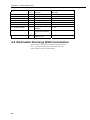
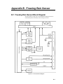
1
0871LH1
Freezing Rain
Sensor
User Manual
Issued 14.1.09
Copyright © 2007 Campbell Scientific (Canada) Corp.
Printed under licence by Campbell Scientific Ltd.
CSL 742
Guarantee
This equipment is guaranteed against defects in materials and
workmanship. This guarantee applies for twelve months from date of
delivery. We will repair or replace products which prove to be defective
during the guarantee period provided they are returned to us prepaid. The
guarantee will not apply to:
•
Equipment which has been modified or altered in any way without the
written permission of Campbell Scientific
•
Batteries
•
Any product which has been subjected to misuse, neglect, acts of God
or damage in transit.
Campbell Scientific will return guaranteed equipment by surface carrier
prepaid. Campbell Scientific will not reimburse the claimant for costs
incurred in removing and/or reinstalling equipment. This guarantee and the
Company’s obligation thereunder is in lieu of all other guarantees,
expressed or implied, including those of suitability and fitness for a
particular purpose. Campbell Scientific is not liable for consequential
damage.
Please inform us before returning equipment and obtain a Repair
Reference Number whether the repair is under guarantee or not. Please
state the faults as clearly as possible, and if the product is out of the
guarantee period it should be accompanied by a purchase order.
Quotations for repairs can be given on request.
When returning equipment, the Repair Reference Number must be clearly
marked on the outside of the package.
Note that goods sent air freight are subject to Customs clearance fees
which Campbell Scientific will charge to customers. In many cases, these
charges are greater than the cost of the repair.
Campbell Scientific Ltd,
Campbell Park, 80 Hathern Road,
Shepshed, Loughborough, LE12 9GX, UK
Tel: +44 (0) 1509 601141
Fax: +44 (0) 1509 601091
Email: [email protected]
www.campbellsci.co.uk
PLEASE READ FIRST
About this manual
Please note that this manual was originally produced by Campbell Scientific Inc. primarily for the
North American market. Some spellings, weights and measures may reflect this origin.
Some useful conversion factors:
Area:
Length:
1 in2 (square inch) = 645 mm2
1 in. (inch) = 25.4 mm
1 ft (foot) = 304.8 mm
1 yard = 0.914 m
1 mile = 1.609 km
Mass:
1 oz. (ounce) = 28.35 g
1 lb (pound weight) = 0.454 kg
Pressure:
1 psi (lb/in2) = 68.95 mb
Volume:
1 UK pint = 568.3 ml
1 UK gallon = 4.546 litres
1 US gallon = 3.785 litres
In addition, while most of the information in the manual is correct for all countries, certain information
is specific to the North American market and so may not be applicable to European users.
Differences include the U.S standard external power supply details where some information (for
example the AC transformer input voltage) will not be applicable for British/European use. Please
note, however, that when a power supply adapter is ordered it will be suitable for use in your country.
Some brackets, shields and enclosure options, including wiring, are not sold as standard items in the
European market; in some cases alternatives are offered. Details of the alternatives will be covered in
separate manuals.
Recycling information
At the end of this product’s life it should not be put in commercial or domestic refuse
but sent for recycling. Any batteries contained within the product or used during the
products life should be removed from the product and also be sent to an appropriate
recycling facility.
Campbell Scientific Ltd can advise on the recycling of the equipment and in some cases
arrange collection and the correct disposal of it, although charges may apply for some
items or territories.
For further advice or support, please contact Campbell Scientific Ltd, or your local agent.
Campbell Scientific Ltd, Campbell Park, 80 Hathern Road, Shepshed, Loughborough, LE12 9GX, UK
Tel: +44 (0) 1509 601141 Fax: +44 (0) 1509 601091
Email: [email protected]
www.campbellsci.co.uk
Contents
PDF viewers note: These page numbers refer to the printed version of this document. Use
the Adobe Acrobat® bookmarks tab for links to specific sections.
1. Purpose ........................................................................ 1
2. General ......................................................................... 1
3. Detailed Principle of Operation .................................. 1
4. Physical Description ................................................... 3
5. Temperature Considerations ...................................... 3
6. Power Interruptions ..................................................... 3
7. Mounting Considerations ........................................... 4
8. Wiring Diagram ............................................................ 5
9. Program Examples ...................................................... 6
9.1 CR1000 ..................................................................................................... 6
9.2 CR23X ...................................................................................................... 7
Figures
1. MSO Circuit Schematic .............................................................................. 2
2. MSO Circuit Sectional View ...................................................................... 2
3. Ice detector ................................................................................................. 3
4. Mounting .................................................................................................... 4
5. Power Supply Connections ......................................................................... 5
6. General Hook-up Diagram ......................................................................... 5
B1. Functional Block Diagram ................................................................... B-1
Tables
A1.
A2.
B1.
B2.
BIT Information .................................................................................. A-2
Serial String Format ............................................................................ A-5
0871KB Ice Detector Qualification Capabilities ................................. B-4
Input/Output Pin Designations ............................................................. B-5
i
Appendices
A. RS-422 Output Format............................ A-1
B. Freezing Rain Sensor ............................. B-1
ii
0871LH1 Freezing Rain Sensor
1. Purpose
This document provides detailed information about the
Goodrich model 0871LH1 Freezing Rain Sensor for
use in ground-based meteorological applications. Topics covered
include requirements, qualification categories and methodology,
and detailed design information.
2. General
The Goodrich 0871LH1 Freezing Rain Sensor is a
one-piece unit that detects the presence of icing condition.
Twenty-four volts DC input power is provided to the freezing
rain sensor. The freezing rain sensor outputs include ice detection
indication and fault status indication. These outputs are provided
through an RS-422 interface and discrete outputs. One freezing
rain sensor is used on each station and provides the primary
means of ice detection. The ice signal is used to indicate to the
operator that an icing condition exists so that appropriate actions
can be taken.
3.
Detailed Principle of Operation
The freezing rain sensor uses an ultrasonically axially vibrating
probe to detect the presence of icing conditions. The sensing
probe is a nickel alloy tube mounted in the strut at its midpoint
(node) with one inch exposed to the elements. This tube exhibits
magnetostrictive properties: it expands and contracts under the
influence of a variable magnetic field. A magnet mounted inside
the strut and modulated by a drive coil surrounding the lower half
of the tube provides the magnetic field.
A magnetostrictive oscillator (MSO) circuit is created with the
above components and the addition of a pickup coil and an
electronic comparator. The ultrasonic axial movement of the tube
resulting from the activation of the drive coil causes a current to
be induced in the pickup coil. The current from the pickup coil
drives the comparator that, in turn, provides the signal for the
drive coil.
The oscillation frequency of the circuit is determined by the
natural resonant frequency of the sensor tube, which is tuned to
40 kHz. With the start of an icing event, ice collects on the
sensing probe. The added mass of accreted ice causes the
frequency of the sensing probe to decrease in accordance with the
laws of classical mechanics. A 0.5 mm (0.020”) thickness of ice
on the probe causes the operating frequency of the probe to
decrease by approximately 130 Hz. Freezing Rain Sensor
software monitors probe frequency, and detects and annunciates
this frequency decrease. At the same time, the internal probe
heater power is applied until the frequency rises to a
predetermined set point plus an additional delay factor to assure
complete de-icing.
1
0871LH1 Freezing Rain Sensor
Once de-iced, the sensing probe cools within a few seconds and
is ready to sense ice formation again. When ice forms on the
sensing probe again to the point where the MSO frequency
decreases by 130 Hz, the sensor de-ices itself again. This cyclic
process is repeated as long as the freezing rain sensor remains in
an icing environment. The ice signal activates at 0.020” ice
accretion and stays on for 60 seconds after the end of the icing
encounter. Specifically, when the output is activated, a 60-second
timer is started. Each time 0.020” forms on the probe, the 60second counter is reset. In effect, the output stays on for 60
seconds after the beginning of the “last” icing encounter.
The Status output indicates whether the freezing rain sensor is
functioning correctly using tests that are described in more detail
in following sections of this document.
Figure 1 MSO Circuit Schematic
Figure 2 MSO Circuit Sectional View
2
User Manual
4. Physical Description
The freezing rain sensor is an integrated unit containing both the
sensor and processing electronics. It contains a 7.35 cm (2.9”)
square faceplate for mounting to the 0871LH1MNT and a 7.28 cm (2.86”)
diameter housing containing the processing electronics.
The unit weighs 318 grams (0.7 lbs), maximum.
Figure 3 Ice Detector
5. Temperature Considerations
WARNING
In the case of unit malfunction causing strut heater lock-on,
the probe temperature can exceed 204.4°C. Maintenance
personnel should exercise caution when servicing the unit.
6. Power Interruptions
The freezing rain sensor is qualified to DO-160C power input
category Z. The unit will remember status through a 200 ms
power interruption, but the output string will cease during the
interruption.
The freezing rain sensor uses a power fail monitor to verify the
supply voltage. If a power fault is detected the freezing rain
sensor is halted with a failure indication on the STATUS discrete
output.
3
0871LH1 Freezing Rain Sensor
7. Mounting Considerations
Prevailing Wind
Figure 4 Mounting (part #0871LH1 MNT)
The freezing rain sensor should be mounted to a sturdy crossarm
located away from buildings or other obstacles that could shadow
the sensing element from freezing rain. The sensor should be
installed so that the sensing probe is a minimum 36 inches above
the ground.
4
1.
Remove the protective tube from strut.
2.
Attach the freezing rain sensor to the mounting bracket using the
supplied ¼ - 20 screws and lock washers. Position the freezing
rain sensor on the mounting pole with the sensing probe pointing
upward, with the bracket inclined at a 20° - 30° angle above
horizontal to ensure proper drainage of melted ice.
3.
Attach to a vertical or horizontal pipe using the supplied V bolts,
nuts and washers. NOTE: The sensor should be mounted so as to
be oriented into the prevailing wind.
4.
Connect cable to connector.
5.
Secure cable to bracket with cable ties.
6.
Remove shipping cover and protective cap prior to powering on
the unit.
User Manual
8.
Wiring Diagram - using cable Part # 0871LH1CBL-L
Datalogger Connections
Description
Colour
CR3000/CR1000
CR10X/CR510
Ice
Blue
Control Port*
Control Port*
Status
Yellow
Control Port*
Control Port*
Power Reference
Black
G
G
Case GND
Green
G
G
5V Power
Purple
5V
5V
Clear
G
G
Shield
*cannot share control ports
Power Connections to Terminal Expander
24 VDC
Red
V+
24V-
Black
V-
Figure 5 Power Supply Connections (part #C2155)
220/
120 VAC
NOTE: Please contact
a certified electrician
to properly install the
power supply.
Figure 6 General Hook-up Diagram
5
0871LH1 Freezing Rain Sensor
9. Program Examples
9.1 CR1000
'Declare Public Variables
Public PTemp, batt_volt
Public TimeCount
Public IceSignal
Public StatusSignal
‘ice signal: 1 = no ice, 0 = ice
‘status signal: 0 = okay, 1 = fault
'Define Data Tables
DataTable (Stat,True,-1)
Sample (1,StatusSignal,FP2)
EndTable
DataTable (Ice,True,-1)
Sample (1,IceSignal,FP2)
EndTable
DataTable (Info,1,-1)
DataInterval (0,15,Sec,10)
Minimum (1,batt_volt,FP2,0,False)
Sample (1,PTemp,FP2)
EndTable
'Main Program
BeginProg
PortsConfig (&B11,&B00)
Scan (5,Sec,0,0)
PanelTemp (PTemp,250)
Battery (Batt_volt)
TimeCount = Timer (1,Sec,0 )
If TimeCount >= 61 then
Portget (IceSignal,1 )
PortGet (StatusSignal,2)
If StatusSignal = 1 then
CallTable Stat
EndIf
If IceSignal = 0 then
CallTable Ice
Timer (1,Sec,3)
EndIf
EndIf
CallTable Info
NextScan
EndProg
6
User Manual
9.2 CR23X
1: Timer (P26)
1: 3 Loc [ Timer ]
2: If (X<=>F) (P89)
1: 3
X Loc [ Timer ]
2: 3
>=
3: 61
F
4: 30
Then Do
3: Set Port(s) (P20)
1: 9999
C8..C5 = nc/nc/nc/nc
2: 9988
C4..C1 = nc/nc/input/input
;This Section will read the status of the ports for comparison.
;**************************************************************
4: Read Ports (P25)
1: 1
Mask (0..255)
2: 2
Loc [ IceStat ]
5: Read Ports (P25)
1: 2
Mask (0..255)
2: 1
Loc [ FaultStat ]
;Check to see if there is a fault in the unit and output it.
;***********************************************************
6: If (X<=>F) (P89)
1: 1
X Loc [ FaultStat ]
2: 1
=
3: 1
F
4: 30
Then Do
7: Do (P86)
1: 10
Set Output Flag High (Flag 0)
8: Set Active Storage Area (P80)^3085
1: 1
Final Storage Area 1
2: 10
Array ID
9: Real Time (P77)^1712
1: 1220
Year,Day,Hour/Minute (midnight = 2400)
10: Sample (P70)^23951
1: 1
Reps
2: 1
Loc [ FaultStat ]
11: End (P95)
;Check to see if there is Ice on the unit and output it.
;*******************************************************
12: If (X<=>F) (P89)
1: 2
X Loc [ IceStat ]
2: 1
=
3: 1
F
4: 30
Then Do
13: Do (P86)
1: 10
Set Output Flag High (Flag 0)
14: Set Active Storage Area (P80)^10755
1: 1
Final Storage Area 1
2: 20
Array ID
7
0871LH1 Freezing Rain Sensor
15: Real Time (P77)^8112
1: 1220 Year,Day,Hour/Minute (midnight = 2400)
16: Sample (P70)^5446
1: 1
Reps
2: 2
Loc [ IceStat ]
;If there is ice on the unit, start a looping sequence that ends only when ice is no longer detected.
;***************************************************************************************
17: Timer (P26)
1: 0
Reset Timer
18: End (P95)
19: End (P95)
8
Appendix A. RS-422 Output Format
A.1 RS-422 Output Format for non-Campbell
Datalogger Applications
This output operates at 9600 BAUD (One Start Bit, 8 Data Bits,
No Parity, One Stop Bit). A 24-byte string is sent once per
second. See section 10.2 for string definition.
A two-line output provides a bi-directional serial port, running at
9600 BAUD (8-bits, one Start Bit, One Stop Bit, no parity), to
allow communication with aircraft electronics and external test
equipment.
NOTE
If access to the digital RS422 data is required with a Campbell
Scientific datalogger this is possible using an SDM-SIO1.
Please contact Campbell Scientific for further details.
A.2 Built-In-Test (BIT)
Built-In-Test (BIT) capabilities of the freezing rain sensor consist
of hardware, continuous, power-up, and operator-initiated tests.
Whenever a failure is detected and verified, the freezing rain
sensor stops detecting and annunciating icing conditions and the
heaters are disabled. Failures detected in Initiated and Continuous
BIT are counted and enunciated once they have been verified. To
eliminate nuisance errors, failures are verified by delaying
(debouncing) the failure for a period of time. Failures detected in
Initiated BIT are latched and power must be cycled on and off to
remove a failure. If failures detected in Continuous BIT go away,
the ice detector changes back to normal mode, and once again
enables all ice detection functions.
A.3 Hardware Built-In-Test (BIT)
Hardware BIT is comprised of a watchdog timer that forces the
microcontroller to re-initialize if it does not receive a strobe every
1.6 seconds. An internal voltage monitor forces the
microcontroller to the reset state if the internal 5VDC power
supply falls below 4.65 VDC and holds it there until the power
supply returns above 4.65 VDC. When the microcontroller is
reset, no output string is sent.
A-1
Appendix A. RS-422 Output Format
A.4 Continuous Built-In-Test (BIT)
Continuous BIT consists of verifying the following:
•
The probe heater is in the correct state. The return leg of the
heater is monitored.
•
The ICE discrete output is in the correct state. The ICE discrete
output is fed back to the microcontroller through a passive
voltage divider and voltage comparator.
•
The MSO is operating correctly. Frequencies between 39000 and
40150 Hz are valid.
•
The probe heater is de-icing correctly. After turn-on, the probe
heater must cause the MSO frequency to return to at least
39970 Hz within the 25 second timeout or it is considered failed.
•
Probe is de-iced within 25 seconds. (De-Icing Fail).
A.5 BIT Failure That Disables Ice Output
The Ice output is disabled due to Continuous and Initiated BIT
failures as shown in Table A1. BIT Information. Ice detection is
disabled when these failures occur because the integrity of the ice
detection capability has been compromised.
Table A1. BIT Information
Title
Disable Ice
Detection 1
Continuous BIT
MSO Fail, High
X
X
MSO Fail, Low
X
X
X
EEPROM Fail
RAM Fail
X
X
ROM Fail
X
X
Watchdog Fail
X
Power Interrupt Timer Fail
X
Power Fault Monitor Fail
Probe Heater Always ON or
OPEN
X
Active Test
Passive Test
Probe Heater Always OFF
Probe Heater ON w/ 1
Enable
Active Test
Passive Test2
De-Icing Fail
Clear Only
Unknown Reset Failure
Ice Output (not contained in
0871KB1 model)
A-2
Initiated BIT
X
Set Only
X
Active Test
Passive Test
Appendix A. RS-422 Output Format
Note 1: When the failure is enunciated, the software no longer provides ice
detection capability.
Note 2: In Continuous BIT, the “Probe Heater Always OFF” failure is set
when the heater is ON and a de-icing failure has been detected. If the
frequency indicates that the ice has been removed within the expected time,
the software will not annunciate the probe heater failure. The actual failure is
most likely due to a problem in the heater feedback circuitry rather than
heater control circuitry. The failure will be enunciated the next time IBIT is
performed.
A.6 Operator-Initiated Tests
The operator can test the freezing rain sensor functionality by
squeezing the tip of the probe between the index finger and thumb. This
simulates icing by decreasing the frequency of the probe.
With the sensor wired to the datalogger use a digital voltmeter
(DVM); measure DC voltage signal between the Ice signal (blue
wire in control port) and the power reference ground (black wire
in G terminal). The voltage reading should be 4500mvDC to
5000mvDC. When the probe tip of the ice detector is squeezed;
thus changing the frequency and tripping the probe, the voltage
reading will immediately drop to a reading below 500mvDC.
Observing this will verify that the probe is operating properly and
give the user enough time to release the probe before it reaches
its full heating temperature.
CAUTION
Once initiated, the heating (de-icing) sequence will
quickly heat the probe to 204.4°C. Though bare fingers
must be used for a reliable test result, there is a danger
that you will burn your fingers if you do not let go when
heating has been verified.
A.7 Initiated Built-In-Test (BIT)
Initiated BIT is performed at initial power-up of the freezing rain
sensor and following power interruptions of not less than 200 ms.
Initiated BIT consists of the following tests:
•
The ice and fault status outputs are set in the RS-422 string and
on the discrete outputs so monitoring electronics or test
equipment can verify activation.
•
The freezing rain sensor heater is turned on for a short period of
time to verify correct operation of the heater, heater control
circuit, and heater feedback circuit.
•
Correct operation of the watchdog timer is verified by simulating
a microcontroller time-out and waiting for a reset input.
•
Proper ROM operation is verified by computing a checksum of
the ROM contents and comparing against a checksum stored in
the ROM.
•
RAM operation is verified by writing and reading test bytes.
A-3
Appendix A. RS-422 Output Format
•
The Power Interrupt Timer is checked by verifying its transitions
to a “warm” state after performing a “cold” start.
•
The power fail input is pulled down to verify a power failure is
detected.
•
Each time the critical data from the Serial EEPROM is read, a
checksum is read and compared to the checksum computed from
the contents. Each time critical data is written to the Serial
EEPROM, a checksum is computed and stored with the data.
•
Resets due to unknown reasons (such as reset from the watchdog
timer) are detected.
Initiated BIT will examine the RESET EEPROM input. If the
input is active, the STATUS output will be set to FAIL and the
ICE output and probe heater will be disabled. (This feature
allows a factory technician to perform the MSO capacitor
selection process without activation of the probe heater.)
Activation of the Press-to-Test (PTT) input for greater than 100
ms also causes the ice detector to perform Initiated BIT. The PTT
input is ignored when the ice output is active. After PTT is
completed, the correlation count is restored to its pre-test value.
Initiated BIT is complete within 3 ± seconds of initial power up.
A.8 Correlation Counting
The freezing rain sensor tracks the amount of ice accumulation
on the probe during an icing encounter. The correlation count is a
value tracked by the freezing rain sensor that indicates the
amount of ice that has accumulated on the probe during the icing
encounter. Each correlation count equals 0.010 inches of ice.
The correlation count, ranging from 0 to 255, indicates the
number of times the MSO frequency decreases by 65 Hz during
an icing encounter. A decrease in frequency of 65 Hz correlates
to an equivalent 0.25 mm of ice that would have formed on the
ice detector probe, neglecting the change in collection efficiency
caused by ice build-up. Upon reaching a correlation count of 255,
the value is no longer incremented.
The freezing rain sensor compensates by adding a value (ranging
from 0 to 6) to the correlation count when the ice detection cycle
is completed, to account for the ice that would have accumulated
if the heater had not been on.
The correlation count is in the serial string, Table A2. Serial String
Format.
The correlation count is initialized to zero at unit power up.
A-4
Appendix A. RS-422 Output Format
Table A2. Serial String Format
Byte
0 (First)
Bit
7
(MSB)
Definition
String ID
May add additional strings in
future
6
5-3
2
Unused
Probe Heater State
1
Ice Output
0
Status Output
1 -2 MSO FREQUENCY
3 - ERRSTAT1
4 - ERRSTAT2
MSO Count in Hex
7
6
5
4
3
2
1
0
7-6
Unused
MSA Fail, Too High
MSO Fail, Too Low
EEPROM Fail
RAM Fail
ROM Fail
Watchdog Fail
Power Interrupt Timer Fail
Probe Heater Failure
5
4
3
2
1
0
De-Icing Fail
Unused
Unused
Unused
Unused
Unused
Power-On Time (In Hex)
in 10-Minute Increments
Cold Start Power-On
Count
Ice Events
Total Failures
Encountered. This
number is incremented
each time the ice detector
transitions from OK to fail.
MSO Frequency Fail
Count
Heater Fail Count
5 - 7 ON-TIME CNT
8 - 9 COLD START CNT
10-11 ICE CNT
12 - FAIL CNT
13 - FAIL DTL 1
Comments/nterpretation/Range
Presently defined as 00
7-4
3-0
1- Heater On
0- Heater Off
1- Ice
0- No Ice
1- Fail
0- (OK) No Fail
Frequency = 774060000/Dec
(MSO)
1 = Active
00 = Probe Heater OK
01 = Probe Heater Always ON or
OPEN
10 = Probe Heater Always OFF
11 = Probe Heater ON with 1
Enable
1 = Active
00 - 01FFFF
00 - FFFF
00 - FFFF
00 - FF
0-F
0-F
A-5
Appendix A. RS-422 Output Format
14 - FAIL DTL 2
7-4
3-0
15 - LAST ERR 1
16 - LAST ERR 2
17 - 2ND LAST ERR 1
18 - 2ND LAST ERR 2
19 - PERM ERR 1
20 - PERM ERR 2
21 - Software Version
7-0
22 - Correlation Count
7-0
23 - CHECKSUM
Not Used
Not Used
See ERRSTAT1 Above
See ERRSTAT2 Above
See ERRSTAT1 Above
See ERRSTAT2 Above
See ERRSTAT1 Above
See ERRSTAT2 Above
Software Version per
VDD/SC1
0.01" ice accretion
increments since poweron
Summation (1-byte wide)
of bytes 0 - 22
Not Used
Not Used
0 - FF
0 - FF
0 - FF
A.9 Electrostatic Discharge (ESD) Consideration
The freezing rain sensor internal components are ESD sensitive,
class 1, so proper ESD precautions must be observed (wrist
straps, conductive surfaces) when handling.
A-6
Appendix B. Freezing Rain Sensor
B.1 Freezing Rain Sensor Block Diagram
The block diagram in Figure B.1. Functional Block Diagram provides an
understanding of the functionality of the freezing rain sensor.
Figure B.1 Functional Block Diagram
B-1
Appendix B. Freezing Rain Sensor
B1.1 Microcontroller
The freezing rain sensor uses an Intel 87C51-type microcontroller
to control the freezing rain sensor functions. This 8-bit
microcontroller requires at least: 4 Kbytes of on-board ROM, 128
bytes of RAM, and 32 input/output ports. The freezing rain
sensor uses about 75% of these resources. Upgraded
microcontrollers that provide more resources are available. The
microcontroller runs at 7.372 MHz.
B1.2 Watchdog/Reset Circuit
The watchdog timer/reset circuit monitors the microcontroller
and provides a reset pulse if not periodically toggled. The
watchdog also provides reset pulses on initial power-up and holds
the microcontroller in the reset state if the internal power supply
falls below an acceptable voltage. The watchdog indicates
impending power loss so the ice detector can shut down in a
known manner.
B1.3 Serial EEPROMB
The Serial EEPROM stores unit status (icing state, failure state,
heater state, correlation count) which is recovered after power
interruptions of 200 ms or less. This allows the unit to meet the
power interruption requirements of RTCA DC-160C, Section 16,
Category Z. Additionally, the Serial EEPROM stores
environmental and failure information such as unit elapsed-time,
number of icing encounters, number of failures, and detailed
information on types and quantities of each annunciated failure.
This information is used by Rosemount Aerospace to confirm
and repair failures reported by the end user and also to collect
MTBF data. Each time the Serial EEPROM is written, a
checksum is computed and written. Each time the Serial
EEPROM is read, a checksum is computed and compared to the
stored value.
B1.4 Probe Oscillator
The probe oscillator is the electronic control portion of the
magnetostrictive oscillator (MSO) used to sense and detect ice.
This circuit provides the drive and feedback of the ice sensing
probe. The circuit drives the probe at a nominal 40kHz, and
converts the feedback into a CMOS compatible square wave that
is measured by the microcontroller. As ice accretes on the probe,
the frequency decreases, and it is this frequency change that the
microcontroller annunciates in the form of Ice Signal #1.
B1.5 Heater Control
The heater control turns the probe heater on and off as
commanded by the microcontroller and monitors the actual heater
state (ON or OFF) for verification by the microcontroller. Two
outputs are required from the microcontroller to turn on the
heater. This minimizes the possibility of an unintended heater ON
condition. The heater control also monitors the state of the heater
B-2
Appendix B. Freezing Rain Sensor
and provides feedback to the microcontroller so that it can be
determined whether the heater is on or off.
B1.6 Drive Coil
The drive coil modulates the magnetic field of the
magnetostrictive oscillator and causes an ultrasonic axial
movement of the probe.
B1.7 Feedback Coil
The feedback coil senses the movement of the probe and when
employed in the probe oscillator circuit, completes the feedback
portion of the MSO.
B1.8 Heater
The probe heater de-ices the probe. It is activated when the
nominal icing trip point of 0.020” is reached and is turned off
five seconds after the MSO has returned to at least 39,970 Hz
(the additional five seconds allows the strut probe time to shed
the de-bonded ice). The maximum heater ON time is 25 seconds.
If the probe frequency has not returned at least 39,970 Hz by that
time, a de-ice failure is declared and the heaters are turned off.
An open circuit of the heater is detected by the microcontroller.
B1.9 DC Power Supply
The DC power supply provides 24 VDC for the heater circuitry.
Internal circuitry converts the 24 VDC input power to 5 VDC for
use by the microcontroller and associated circuits. It employs a
large input capacitor to provide enough time between detection of
input power loss and actual loss of DC power, for the
microcontroller to store the current unity status in the non-volatile
memory. The DC power supply provides input transient
protection to meet RTCA DO-160C power input, voltage spike,
and lightning requirements.
B1.10 Status Output
The status output provides a ground output when the freezing rain
sensor is operating correctly, and high impedance (200 KΩ
minimum) when the unit has detected a failure. Failures are
detected through continuous and initiated tests. The Status output
is capable of sinking 50 mA and is guaranteed to be no more than
1.5 VDC with respect to Signal Return when active. This output
is transient protected to meet RTCA DO-160C lightning
requirements and to prevent stray high-voltage from coupling
into the unit and damaging the output transistor.
B1.11 Ice Signal Output
The Ice Signal output provides a ground output for 60 ±
6 seconds when the ice detector has detected the presence of ice
B-3
Appendix B. Freezing Rain Sensor
(frequency drop of 130 Hz, equivalent to approximately 0.020” ice
formation). If the frequency subsequently decreases by 130 Hz while the Ice
Signal output timer is non-zero, the timer is reinitialized to 60 seconds.
The output is transient protected to meet RTCA DO-160C lightning
requirements and to prevent stray high-voltage from coupling into the unit
and damaging the output transistor.
The ice output has feedback to the microcontroller for software to verify it is
in the correct state for more built in test coverage. The software in the
0871KB2 model uses this feedback to verify that the ice output is operating
correctly. However, in the 0871KB1 model, the software does not use this
input.
To interface to the 0871 KB, the power supply must provide a pull-up to 5 to
28 volts. When the ice output is inactive (open), the nominal resistance to
ground is 13.4 KΩ. The power supply should source at least 0.250 mA to
provide the proper signal to the Ice Signal feedback circuitry. When the
output is active (closed), it is capable of sinking 50 mA and is guaranteed to
be no more than 1.5 VDC with respect to Signal Return.
Table B.1 0871KB Ice Detector Qualification Capabilities
Test Name
EMC
Test Requirement
DO-160C:
Audio Freq Susc:
Lightning Induced Susceptibility
Cat Z
Induced Signal:
Cat Z
Susc:
Chg Notice 3, Cat R
RF Susceptibility:
Cat Z
RF Emissions:
Cat Z
DO-160C:
Multiple Burst:
Waveform 3 & 4: Level 3
Multiple Stroke:
Waveform 3: Level 3
Temperature Variation
DO-160C:
Cat A
Temperature/Altitude
DO-160C:
Cat D2 (-40°C to +71°C)
Vibration
DO-160C:
Cat E (Random, 7.9 grms)
Operation Shock, Crash Safety
DO-160C:
Shock
Salt Spray
DO-160C:
Cat S
Humidity
DO-160C:
Cat B
Icing Performance
Rosemount Aerospace, Inc. Test Procedure
Power Input
DO-160C:
Cat Z, 18 - 29.5 VDC
Voltage Spike
DO-160C:
Cat A
Magnetic Effect
Bonding
DO-160C:
Cat A (1 deflection at 0.5m)
2.5 mΩ Max. Mounting Plate to Aircraft Structure
10 mΩ Max. Connector Shell to Mounting Plate
Dielectric Withstanding
Insulation Resistance
MIL-STD 202, 500 VDC, 1000 MΩ, EMI Filters Disconnected
Fluid Susceptibility
DO-160C:
Cat F
Waterproofness
DO-160C:
Cat W
Fungus Resistance
DO-160C:
Cat F
Sand and Dust
DO-160C:
Cat D
Direct Lightning Strike
DO-160C:
Cat 1A
Software
DO-178B used as a guideline
B-4
MIL-STD 202, 500 VAC, 60 Hz, EMI Filters Disconnected
Appendix B. Freezing Rain Sensor
Table B.2 Input/Output Pin Designations
Signal Name
Connector
Pin
Input or
Output
24VDC
A
24VDC Return
B
Case Ground
RS-422 High
RS-422 Low
Ice
C
D
E
F
Input
Input
Output
Output
Output
Status
G
Output
Input
Definition
18-29.5 VDC**
------Per RS-422 Spec
Per RS-422 Spec
Ground Active (1.5 VDC Max)
Open Inactive
Ground Active (1.5 VDC Max)
Open Inactive
Current
Wire
Gauge
1.5 Amp Max at
28VDC
20
------Per RS-422 Spec
Per RS-422 Spec
0.5 - 50 mA
20
20
20-24
20-24
20-24
0.5 - 50 mA
20-24
**Ice will be correctly detected between these voltages. Proper probe de-icing, however, is only guaranteed
when input voltage is 24VDC or greater.
B-5
CAMPBELL SCIENTIFIC COMPANIES
Campbell Scientific, Inc. (CSI)
815 West 1800 North
Logan, Utah 84321
UNITED STATES
www.campbellsci.com
[email protected]
Campbell Scientific Africa Pty. Ltd. (CSAf)
PO Box 2450
Somerset West 7129
SOUTH AFRICA
www.csafrica.co.za
[email protected]
Campbell Scientific Australia Pty. Ltd. (CSA)
PO Box 444
Thuringowa Central
QLD 4812 AUSTRALIA
www.campbellsci.com.au
[email protected]
Campbell Scientific do Brazil Ltda. (CSB)
Rua Luisa Crapsi Orsi, 15 Butantã
CEP: 005543-000 São Paulo SP BRAZIL
www.campbellsci.com.br
[email protected]
Campbell Scientific Canada Corp. (CSC)
11564 - 149th Street NW
Edmonton, Alberta T5M 1W7
CANADA
www.campbellsci.ca
[email protected]
Campbell Scientific Ltd. (CSL)
Campbell Park
80 Hathern Road
Shepshed, Loughborough LE12 9GX
UNITED KINGDOM
www.campbellsci.co.uk
[email protected]
Campbell Scientific Ltd. (France)
Miniparc du Verger - Bat. H
1, rue de Terre Neuve - Les Ulis
91967 COURTABOEUF CEDEX
FRANCE
www.campbellsci.fr
[email protected]
Campbell Scientific Spain, S. L.
Psg. Font 14, local 8
08013 Barcelona
SPAIN
www.campbellsci.es
[email protected]
Campbell Scientific Ltd. (Germany)
Fahrenheitstrasse13, D-28359 Bremen
GERMANY
www.campbellsci.de
[email protected]
Please visit www.campbellsci.com to obtain contact information for your local US or International representative.