1
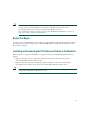
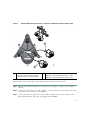
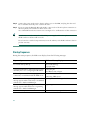
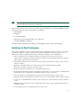
Phone Guide
Cisco Unified IP Conference Station 7936
License and Warranty
1
Getting Started
2
Installation
3
Features and Functions
4
Cisco Unified IP Conference Station 7936 Web Interface
5
Using the Cisco Unified IP Conference Station 7936
6
General Troubleshooting Information
7
Obtaining Documentation
8
Documentation Feedback
9
Obtaining Technical Assistance
10 Obtaining Additional Publications and Information
11 Cisco One-Year Limited Hardware Warranty Terms
1 Getting Started
This guide helps you quickly set up and use the Cisco Unified IP Conference Station 7936
(Cisco model number CP-7936). The IP Conference Station requires Cisco Unified CallManager, and
your system administrator must prepare the network for the IP Conference Station. Verify with your
system administrator that the network is ready for the IP Conference Station. Be sure to read Release
Notes for Cisco Unified IP Conference Station 7936 and both the “Package Contents” section on
page 2 and the “Safety Notices” section on page 3 before you begin to set up and use the IP Conference
Station.
Note
If your IP Conference Station is already set up, skip to the “Features and Functions” section
on page 17.
Introduction
The Cisco Unified IP Conference Station 7936 is an IP-based, hands-free conference room station that
uses Voice over IP (VoIP) technology. The IP Conference Station replaces a traditional analog
conferencing unit by providing business conferencing features—such as Call Hold, Call Resume, Call
Transfer, Call Release, Call Pickup, Group Pickup, Redial, Mute, and Conference—over an IP
network.
The Cisco Unified IP Conference Station 7936 features two outboard microphone jacks to enable the
use of optional, external microphones. Along with its enhanced speaker design, the IP Conference
Station is ideal for use in larger-sized conference rooms to facilitate conference calling. The
Cisco Unified IP Conference Station 7936 can also be ordered without external microphones for use
in smaller offices and conference rooms.
Package Contents
Review the following list to be sure that you have received all of the necessary items to install the
Cisco Unified IP Conference Station 7936.
• One Cisco Unified IP Conference Station 7936
• One 6-foot CAT 5 Cable
• One 25-foot CAT 5 Cable
• One Power Interface Module (PIM)
• One Power Supply Unit (a country-specific power cord must be ordered separately)
• Optional External Microphone Kit (with two external microphones), ordered separately
• One Regulatory Compliance and Safety Information Guide
2
Safety Notices
These are the safety considerations for using the IP Conference Station. Read these notices before you
install or use the IP Conference Station.
Statement 1071—Warning Definition
Warning
IMPORTANT SAFETY INSTRUCTIONS
This warning symbol means danger. You are in a situation that could cause
bodily injury. Before you work on any equipment, be aware of the hazards
involved with electrical circuitry and be familiar with standard practices for
preventing accidents. Use the statement number provided at the end of each
warning to locate its translation in the translated safety warnings that
accompanied this device. Statement 1071
SAVE THESE INSTRUCTIONS
Waarschuwing
BELANGRIJKE VEILIGHEIDSINSTRUCTIES
Dit waarschuwingssymbool betekent gevaar. U verkeert in een situatie die
lichamelijk letsel kan veroorzaken. Voordat u aan enige apparatuur gaat
werken, dient u zich bewust te zijn van de bij elektrische schakelingen
betrokken risico's en dient u op de hoogte te zijn van de standaard praktijken
om ongelukken te voorkomen. Gebruik het nummer van de verklaring
onderaan de waarschuwing als u een vertaling van de waarschuwing die bij
het apparaat wordt geleverd, wilt raadplegen.
BEWAAR DEZE INSTRUCTIES
Varoitus
TÄRKEITÄ TURVALLISUUSOHJEITA
Tämä varoitusmerkki merkitsee vaaraa. Tilanne voi aiheuttaa ruumiillisia
vammoja. Ennen kuin käsittelet laitteistoa, huomioi sähköpiirien
käsittelemiseen liittyvät riskit ja tutustu onnettomuuksien yleisiin
ehkäisytapoihin. Turvallisuusvaroitusten käännökset löytyvät laitteen
mukana toimitettujen käännettyjen turvallisuusvaroitusten joukosta
varoitusten lopussa näkyvien lausuntonumeroiden avulla.
SÄILYTÄ NÄMÄ OHJEET
3
Attention
IMPORTANTES INFORMATIONS DE SÉCURITÉ
Ce symbole d'avertissement indique un danger. Vous vous trouvez dans une
situation pouvant entraîner des blessures ou des dommages corporels. Avant
de travailler sur un équipement, soyez conscient des dangers liés aux circuits
électriques et familiarisez-vous avec les procédures couramment utilisées
pour éviter les accidents. Pour prendre connaissance des traductions des
avertissements figurant dans les consignes de sécurité traduites qui
accompagnent cet appareil, référez-vous au numéro de l'instruction situé à la
fin de chaque avertissement.
CONSERVEZ CES INFORMATIONS
Warnung
WICHTIGE SICHERHEITSHINWEISE
Dieses Warnsymbol bedeutet Gefahr. Sie befinden sich in einer Situation, die
zu Verletzungen führen kann. Machen Sie sich vor der Arbeit mit Geräten mit
den Gefahren elektrischer Schaltungen und den üblichen Verfahren zur
Vorbeugung vor Unfällen vertraut. Suchen Sie mit der am Ende jeder Warnung
angegebenen Anweisungsnummer nach der jeweiligen Übersetzung in den
übersetzten Sicherheitshinweisen, die zusammen mit diesem Gerät
ausgeliefert wurden.
BEWAHREN SIE DIESE HINWEISE GUT AUF.
Avvertenza
IMPORTANTI ISTRUZIONI SULLA SICUREZZA
Questo simbolo di avvertenza indica un pericolo. La situazione potrebbe
causare infortuni alle persone. Prima di intervenire su qualsiasi
apparecchiatura, occorre essere al corrente dei pericoli relativi ai circuiti
elettrici e conoscere le procedure standard per la prevenzione di incidenti.
Utilizzare il numero di istruzione presente alla fine di ciascuna avvertenza per
individuare le traduzioni delle avvertenze riportate in questo documento.
CONSERVARE QUESTE ISTRUZIONI
Advarsel
VIKTIGE SIKKERHETSINSTRUKSJONER
Dette advarselssymbolet betyr fare. Du er i en situasjon som kan føre til skade
på person. Før du begynner å arbeide med noe av utstyret, må du være
oppmerksom på farene forbundet med elektriske kretser, og kjenne til
standardprosedyrer for å forhindre ulykker. Bruk nummeret i slutten av hver
advarsel for å finne oversettelsen i de oversatte sikkerhetsadvarslene som
fulgte med denne enheten.
TA VARE PÅ DISSE INSTRUKSJONENE
4
Aviso
INSTRUÇÕES IMPORTANTES DE SEGURANÇA
Este símbolo de aviso significa perigo. Você está em uma situação que poderá
ser causadora de lesões corporais. Antes de iniciar a utilização de qualquer
equipamento, tenha conhecimento dos perigos envolvidos no manuseio de
circuitos elétricos e familiarize-se com as práticas habituais de prevenção de
acidentes. Utilize o número da instrução fornecido ao final de cada aviso para
localizar sua tradução nos avisos de segurança traduzidos que acompanham
este dispositivo.
GUARDE ESTAS INSTRUÇÕES
¡Advertencia!
INSTRUCCIONES IMPORTANTES DE SEGURIDAD
Este símbolo de aviso indica peligro. Existe riesgo para su integridad física.
Antes de manipular cualquier equipo, considere los riesgos de la corriente
eléctrica y familiarícese con los procedimientos estándar de prevención de
accidentes. Al final de cada advertencia encontrará el número que le ayudará
a encontrar el texto traducido en el apartado de traducciones que acompaña
a este dispositivo.
GUARDE ESTAS INSTRUCCIONES
Varning!
VIKTIGA SÄKERHETSANVISNINGAR
Denna varningssignal signalerar fara. Du befinner dig i en situation som kan
leda till personskada. Innan du utför arbete på någon utrustning måste du vara
medveten om farorna med elkretsar och känna till vanliga förfaranden för att
förebygga olyckor. Använd det nummer som finns i slutet av varje varning för
att hitta dess översättning i de översatta säkerhetsvarningar som medföljer
denna anordning.
SPARA DESSA ANVISNINGAR
5
6
Statement 1007—TN and IT Power Systems
Warning
This equipment has been designed for connection to TN and IT power systems. Statement
1007
Waarschuwing
Varoitus
Deze apparatuur is ontworpen voor verbindingen met TN en IT
energiesystemen.
Tämä laitteisto on suunniteltu yhdistettäväksi TN- ja
IT-sähkövoimajärjestelmiin.
Attention
Ce matériel a été conçu pour être connecté à des systèmes d'alimentation TN
et IT.
Warnung
Dieses Gerät ist so konstruiert, daß es an TN- und IT-Stromsysteme
angeschlossen werden kann.
7
Avvertenza
Questa apparecchiatura è stata progettata per collegamenti a sistemi di
alimentazione TN e IT.
Advarsel
Dette utstyret er utformet for å kunne kobles til TN- og IT-strømsystemer.
Aviso
¡Advertencia!
Varning!
Este equipamento foi criado para ligações a sistemas de corrente TN e IT.
Este equipo se ha diseñado para ser conectado a sistemas de alimentación
tipo TN o IT.
Denna utrustning har konstruerats för anslutning till elkraftssystem av TN- och
IT-typ.
Warning
Read the installation instructions before you connect the system to its power source.
Warning
Only trained and qualified personnel should be allowed to install, replace, or service this
equipment.
8
Warning
Ultimate disposal of this product should be handled according to all national laws and
regulations.
Warning
Do not work on the system or connect or disconnect cables during periods of lightning
activity.
Warning
To avoid electric shock, do not connect safety extra low voltage (SELV) circuits to
telephone network voltage (TNV) circuits. LAN ports contain SELV circuits, and WAN
ports contain TNV circuits. Some LAN and WAN ports both use RJ-45 connectors. Use
caution when connecting cables.
Warning
This product relies on the building's installation for short-circuit (overcurrent)
protection. Ensure that a fuse or circuit breaker no larger than 120 VAC, 15 A U.S.
(240 VAC, 10 A international) is used on the phase conductors (all current-carrying
conductors).
Warning
The plug-socket combination must be accessible at all times because it serves as the
main disconnecting device.
Caution
The Cisco Unified IP Conference Station 7936 is inoperable during a power outage if it is
not supported by a UPS (uninterruptible power supply) when using a local power supply
unit. This affects your ability to reach 911.
Caution
Using a cell, mobile, or GSM phone, or a two-way radio in close proximity to a
Cisco Unified IP Phone might cause interference. For more information, refer to the
manufacturer’s documentation of the interfering device.
9
To see additional safety warnings and translations of the safety warnings that appear in this
publication, refer to the Regulatory Compliance and Safety Information for the
Cisco Unified IP Phone 7900 Series that is shipped with your Cisco Unified
IP Conference Station 7936.
Note
Using External Devices with Your Cisco Unified IP Phone
The following information applies when you use external devices with the Cisco Unified IP Phone:
• Depending on the quality of these devices and their proximity to other devices such as mobile
phones or two-way radios, some audio noise may still occur. In these cases, Cisco recommends
that you take one or more of the following actions:
– Move the external device away from the source of the RF or AF signals.
– Route the external device cables away from the source of the RF or AF signals.
– Use screened cables for the external device, or use cables with a better screen and connector.
– Shorten the length of the external device cable.
– Apply ferrites or other such devices on the cables for the external device.
• Cisco cannot guarantee the performance of the system because Cisco has no control over the
quality of external devices, cables, and connectors. The system will perform adequately when
suitable devices are attached using good quality cables and connectors.
Caution
In European Union countries, use only external speakers, microphones, and headsets that
are fully compliant with the EMC Directive [89/336/EC].
For more information on regulatory compliance and safety information, refer to the Regulatory
Compliance and Safety Information for the Cisco Unified IP Phone 7900 Series.
Accessibility Features
A list of accessibility features is available upon request.
2 Installation
This section provides basic installation instructions and information about obtaining optimal
performance with the Cisco Unified IP Conference Station 7936.
10
Note
Be sure to review the “Package Contents” section on page 2 and the “Safety Notices” section
on page 3. Also read the Regulatory Compliance and Safety Information for the
Cisco Unified IP Phone 7900 Series, along with the Release Notes for
Cisco Unified IP Conference Station 7936. See the “Related Documentation” section on
page 17 for a list of relevant documentation.
Before You Begin
To ensure a successful installation, verify with your system administrator that the network is ready for
the IP Conference Station and that Cisco Unified CallManager is installed and configured for the
IP Conference Station.
Installing and Connecting the IP Conference Station to the Network
Refer to Figure 1 on page 12 and Figure 2 on page 13 when you are installing the IP Conference
Station.
• Figure 1 shows the various components and power and cable connections used on the
Cisco Unified IP Conference Station 7936.
• Figure 2 shows the optional, external microphones and their connection to the external
microphone jacks on the bottom of the Cisco Unified IP Conference Station 7936.
Note
Daisy-chaining Cisco Unified IP Conference Stations to other Cisco Unified IP Phones is not
a supported configuration and will not work.
11
Figure 1
Cisco Unified IP Conference Station 7936—Components and Connections
1
4
3
2
5
+
6
+
10
8
9
Foot
pad
99373
7
1
Power outlet in the wall
6
RJ-45 port on the bottom of the
IP Conference Station
2
Power supply power cord
7
Free end of the 25-foot CAT 5 cable
3
Power supply unit power cord 8
LAN connection on PIM
4
PIM
9
25-foot CAT 5 cable connection on PIM
5
LAN connection
10 DC adapter port on PIM for power supply unit
12
External Microphone Connections on the Cisco Unified IP Conference Station 7936
2
1
2
105036
Figure 2
1
1
Connect one end of the external
microphone cable to the jack on the
underside of the external microphone.
2
Connect the other end of the external microphone
cable to the external microphone jack on the
underside of the IP Conference Station 7936.
Perform these steps to install and connect the IP Conference Station to the network.
Step 1
Place the IP Conference Station on a flat surface, for example, a conference room table or
desktop.
Step 2
Connect one end of the 6-foot CAT 5 cable to your data network port and connect the other
end to the network (LAN) port on the PIM.
Step 3
Connect the free end of the 25-foot CAT 5 cable to the RJ-45 port on the bottom of the
IP Conference Station. (The cable is preplugged into the PIM.)
13
Step 4
Connect the power supply unit to the AC adapter port on the PIM, and plug the other end
into a standard electrical power outlet in the wall.
Step 5
If you are using the External Microphone Kit, connect each of the microphone extensions to
the microphone jacks installed on the bottom of the
Cisco Unified IP Conference Station 7936. See Figure 2 for an illustration of this connection.
Tip
If you do not correctly connect the cables, PIM, power supply, and the microphone extensions,
the IP Conference Station will not work.
Use of non-Cisco-certified components may not work and may void the IP Conference Station
product warranty.
Startup Sequence
During the startup sequence, the LCD screen display shows the following messages.
Sequence Step
LCD Screen Message Display
Startup—The startup process occurs about
15 seconds after power up.
Cisco Systems, Inc.
Polycom Technology
Copyright 2003
Configuring IP address—These messages appear
when the protocol is configuring the IP address.
Configuring IP
Press Menu to Reconfigure
TFTP configuration—This message appears when Station IP: IP address
connectivity is established with the TFTP server. Contacting: TFTP Server
Cisco Unified CallManager configuration—This Opening: Cisco CallManager IP address
message appears when connectivity is established
with the Cisco Unified CallManager.
Cisco Unified CallManager registration—This
message appears while the device is registering
with the Cisco Unified CallManager.
Registering
Initialization complete.
Press the Phone Key to get a dial tone
14
Note
The startup process may take several minutes, and some of these messages may not appear
because of the access speed of your network.
After the IP Conference Station has successfully registered with the Cisco Unified CallManager, the
following information appears in the LCD screen display:
• Date and time
• IP address
• Local phone number
• The message “Press the Phone Key to get a dial tone”
• Corp Dir and Ph Book softkeys
If the IP Conference Station successfully passes through these steps, it has started properly.
Guidelines for Best Performance
Follow these guidelines to ensure optimum performance with the IP Conference Station 7936 and the
external microphones. See the “Conference Room Setup Examples” section on page 16 for an
illustration of proper equipment placement for different conference room configurations.
• The recommended room conditions include closed offices and conference rooms up to
20 feet x 20 feet (without external microphones) and 20 feet x 30 feet (with external microphones)
without major glass and/or ceramic surface.
• Place the IP Conference Station 7936 base on a flat surface and make sure that it is clear from any
reflective surfaces.
• Maintain a minimum distance of 4 feet between each external microphone and the
IP Conference Station 7936 base and other objects.
• Make sure that all microphones are acoustically unobstructed.
• Position the external microphones toward the areas that need to be covered, and so that the main
pickup direction is pointed away from the IP Conference Station 7936 base.
• Seat all conference participants the same distance from the IP Conference Station 7936.
• Speak at normal conversation levels and direct your voice toward the IP Conference Station 7936.
• Do not move or handle the IP Conference Station 7 936 base or the external microphones while on
a call.
• Minimize background noise from air conditioning units, fans, or other equipment in the office or
conference room.
• Do not shuffle papers near the IP Conference Station 7936.
15
Conference Room Setup Examples
See Figure 3 on page 16 for examples of proper placement of the IP Conference Station 7936 base and
external microphones in different conference room configurations.
Cisco Unified IP Conference Station 7936 Base and External Microphone Placement
105064
Figure 3
16
Where to Go for Help
If you require additional information or assistance with the IP Conference Station, contact your system
administrator. For technical assistance information, see the “Obtaining Technical Assistance” section
on page 42.
Related Documentation
In addition to this Cisco Unified IP Conference Station 7936 Phone Guide, you can reference the
following publications, which are available online at the URL listed below:
• Cisco Unified IP Conference Station 7936 Administration Guide
• Guidelines for Using External Microphones with the Cisco Unified IP Conference Station 7936
• Release Notes for Cisco Unified IP Conference Station 7936
• Regulatory Compliance and Safety Information for the Cisco Unified IP Phone 7900 Series
(included with your IP Conference Station, and available online)
These publications are available on the web at the following URL:
http://www.cisco.com/univercd/cc/td/doc/product/voice/c_ipphon/english/ipp7936/index.htm
For more documentation information, see the “Obtaining Documentation” section on page 40.
3 Features and Functions
This section describes the features and functions of the Cisco Unified IP Conference Station 7936.
Features of the Cisco Unified IP Conference Station 7936
The IP Conference Station provides business audio conferencing features and functions, as described
in the “Introduction” section on page 2.
See Figure 4 on page 18 and its supporting table for an illustration and an explanation of the features
and functions of the Cisco Unified IP Conference Station 7936.
17
Figure 4
Cisco Unified IP Conference Station 7936—Features and Functions
1
2
3
4
12
5
11
6
10
8
18
99374
7
9
1
LEDs
Provide call status indicators.
Call State Off—All LEDs off.
Powering On—Red LEDs on.
Ready—All LEDs off.
Dial Tone On—Green LEDs on.
Dialing—Green LEDs blinking.
Connected—Green LEDs on.
Mute—Red LEDs blinking.
Hold—Red LEDs on.
Incoming Call—Green LEDs blink with ring.
Ringing/Connecting—Green LEDs blinking.
2
LCD screen
Provides a status indicator that reads “Press the Phone Key to get a dial
tone” when the IP Conference Station is online and fully operational. In
the resting display, the LCD screen shows the date and time, IP address,
and local phone number assigned to the IP Conference Station. It also
displays the IP Conference Station system status, including configuration
and all administrative settings. The LCD screen is backlit.
3
Scroll buttons
Allow you to scroll through the menus or through an open list in the LCD
screen.
4
Select button
Selects a menu option or list item that is highlighted.
19
5
Softkeys
Answer—Picks up the current call.
CFwdAll—Redirects all of your incoming calls to another number.
Confrn—Adds a party to a conference call.
Corp Dir—Lets you search a corporate directory for a number to call.
EndCall—Ends a call and returns to the resting display or to the active
call list.
GPickUp—Lets you pick up a call within your group or another group.
Hold—Puts the active call on hold.
PickUp—Lets you pick up a call within your group.
Ph Book—Opens the phone book.
NewCall—Lets you dial a new number.
Resume—Returns to the selected call on hold.
Transfer—Transfers the current call.
6
Volume buttons
Increase or decrease the volume of the call, speaker, ringer, or dial tone,
depending on which sound is currently active.
7
Mute button
Turns call muting on or off.
8
Keypad
Allows you to dial phone numbers, add or edit phone book entries, and
enter other input depending on the menu selected.
9
Redial button
Automatically redials the last dialed number.
20
10
Phone button
Allows you to get dial tone, answer an incoming call, and hang up a call.
11
Exit button
Returns to the resting LCD screen from a menu, a list, or the phone book.
12
Menu button
Opens and closes the main menu on the IP Conference Station. The main
menu includes the following selections:
Call Functions—Opens the call function options, including Meet-me,
Park, Pick-up, Group Pick-up, Transfer, Remove Last Participant and
Join.
Phone Book—Opens the phone book.
Settings—Opens the Settings options, including Contrast, Language,
Ringer, Time Format, and Date Format.
Admin Setup—Opens Admin Setup (requires administrator password).
4 Cisco Unified IP Conference Station 7936 Web Interface
This section describes the web interface for the Cisco Unified IP Conference Station 7936.
Description of the Web Interface
Some of the features and functions of the IP Conference Station can be configured through the
Cisco Unified IP Conference Station 7936 web interface.
The IP Conference Station web interface appears in your web browser as a tri-pane window. The
browser menu and toolbar appear at the top of the window, the Table of Contents links appear in the
left navigation pane, and the linked information and configuration fields appear in the right pane. A
banner also appears in the top right corner of the right pane and remains persistent through all the
pages in the web interface. The banner information includes software version, protocol type, boot load
ID, application load ID, IP address, MAC address, and local number.
The content of the web interface is different for administrators and end users. Both the administrator
and end-user views require login passwords. If you are an administrator, refer to the
Cisco Unified IP Conference Station 7936 Administration Guide for information on administrator
settings available in the web interface.
21
Using the Web Interface
Perform these steps to access the IP Conference Station web interface.
Step 1
Open your web browser.
Step 2
In the address field, enter the IP address of the specific IP Conference Station that you want
to configure.
http://<IP address of the IP Conference Station>:<HTTP Port Number>
where HTTP Port Number is the number assigned by your system administrator. If this
number is not assigned, you do not need to enter it. Contact your system administrator if you
have difficulty opening the web interface.
The initial Login page on the web interface appears.
Step 3
In the password field, enter the end-user password and click Login.
Note
Step 4
The default end-user password is 7936. If you do not know the password, contact
your system administrator.
To log off, click User Logout.
End-User Settings
The end-user settings include the following web pages:
• Phone Book
• Sounds
• Time & Date
• Diagnostics
• Password Change
All the web pages include online help information through the “i” icon. Each page is described in the
sections that follow.
Phone Book
The Phone Book web page lets you quickly add, delete, and edit entries. You can view entries by
alphabetical sequence or by phone number. You can also dial numbers from the phone book.
22
Using the Phone Book Web Page
• Click Phone Book in the navigation pane.
• To view the entries by alphabetic sequence, click one of the letter combinations. For example to
view entries beginning with the letter “D,” click DEF.
• To view the entries by phone number, click Dial Numbers only.
• To place a call, select an entry and click Dial.
Adding an Entry
Step 1
Click the Add button.
Step 2
Enter the phone number, last name and first name, and company name.
The phone number and last name are required entries.
Step 3
Click Add New Entry.
Repeat these steps to add other entries to the phone book.
Deleting an Entry
Step 1
Select an entry.
Step 2
Click the Delete button.
Step 3
Confirm the deletion by clicking the Delete button again.
Editing an Entry
Step 1
Select an entry.
Step 2
Click the Edit button.
Make changes to the entry.
Step 3
Click the Update button to save your changes.
23
Sounds
The Sounds web page lets you select the ringer sound and the dial tone.
Opening the Sounds Web Page
• Click Sounds in the navigation pane.
Changing the Ringer Sound
Step 1
Select a ringer sound from the list box.
There are five ringer sounds—Pro, Biz, Euro, Chirp, and Bell.
If you select Ringer Off, the ringer sound on the IP Conference Station is turned off.
Step 2
Click Set Ringer.
Step 3
Click Test Ringer to hear the sound that you selected.
Time & Date
The Time & Date web page lets you change the time and date formats that display in the LCD screen.
Opening the Time & Date Web Page
• Click Time & Date in the navigation pane.
Changing the Time Format
• Select the 12-hour clock option button for 12-hour time format.
• Select the 24-hour clock option button for 24-hour time format.
• Click Change to save your changes.
Changing the Date Format
• Select the MM/DD/YY option button for a month/date/year format.
• Select the DD/MM/YY option button for a date/month/year format.
• Select the YY/MM/DD option button for a year/month/date format.
• Click Change to save your changes.
24
Diagnostics
The Diagnostics web page lets you test network connectivity to another device.
Opening the Diagnostics Web Page
• Click Diagnostics in the navigation pane.
Pinging Another Device
Step 1
Enter the IP address or name of the device that you want to ping.
Step 2
Click Ping.
You should receive a response from the device.
Password Change
The Password Change page lets you change your user password.
Opening the Password Change
• Click Password Change in the navigation pane.
Changing Your Password
Step 1
In the Old User Password box, enter the current user password.
Step 2
In the New User Password box, enter the new user password.
Step 3
In the Confirm User Password box, enter the new user password again.
Step 4
Click Change.
5 Using the Cisco Unified IP Conference Station 7936
The IP Conference Station 7936 supports a maximum of two calls on a single line. The phone’s control
panel includes 25 keys; an LCD screen provides for information display.
When you press the Phone key on the IP Conference Station 7936, the phone goes off-hook and a dial
tone is heard. The dial sequence begins, and three LEDs are turned on (green) to indicate an active
state. If a call is received while you are on an active call, a call waiting tone is played.
25
A backlight illuminates the LCD screen on the IP Conference Station 7936. This backlight is turned
on whenever a key is pressed. The backlight is turned off when the IP Conference Station 7936 is not
used or when a call exceeds one minute. If a second call is received when a call is in progress and the
backlight is turned off, the light will be turned back on.
The IP Conference Station 7936 includes three context-sensitive keys, a menu access and exit key, and
scroll and select keys. The following functions are accessible via these keys:
• Call interface
• Configuration interface
• Additional call functions (functions that are not accessible through the softkeys)
• Phone book access (a local phone book is available to store up to 20 numbers)
User Options
The following user options are available by using the LCD menu.
LCD Menu Item
Description
Call Functions—Access these features as follows: Call Functions provides access to calling features
that are not available from the softkeys, such as
1. Press the Menu button.
Meet-me, Park, Pick-up, Group Pick-up,
2. Press the Up or Down scroll button to select Transfer, Remove Last Participant and Join.
Call Functions.
3. Press the Select button.
Phone Book—Access the phone book by
following the procedure above and selecting
Phone Book, or press the Ph Book softkey from
the phone’s resting display menu.
Access to the phone book enables you to enter
new phone book entries and to place calls from
phone book entries that you have made. The
phone book holds up to 20 entries.
Settings—Access the user-modifiable settings by
following the procedure above and selecting
Settings.
The user-modifiable settings include LCD
contrast, ringer, time format, and date format.
Configuration options are also accessible through the Cisco Unified IP Conference Station 7936 web
interface. See the “Cisco Unified IP Conference Station 7936 Web Interface” section on page 21.
The following section provides step-by step instructions for using the features and functions of the
Cisco Unified IP Conference Station 7936.
26
Basic Features
Placing a Call
Step 1
Press the Phone button.
Step 2
Dial the number.
Answering a Call
• Press the Phone button or the Answer softkey.
The active call appears in the active call list in the LCD screen.
Ending a Call
• Press the Phone button or the End Call softkey.
Placing a Call on Hold
Step 1
While on a call, press the Hold softkey.
The held call appears in the active call list in the LCD screen.
To place another call, press the New Call softkey and then dial the number.
Step 2
To return to the call-on-hold, press the Resume softkey.
Step 3
If multiple calls on are on hold, press the Up or Down scroll button to select a call in the active
call list and then press the Resume softkey.
Redialing a Call
• Press the Redial button to dial the last number called.
27
Muting a Call
Step 1
While on a call, press the Mute button.
The LEDs blink red, and a Mute icon appears in the LCD screen display.
Step 2
To turn off Mute, press the Mute button again.
Tip
You can also mute a call by pressing the Mute button on one of the external microphones, if
installed.
Conference Calls
Placing a Conference call
Step 1
Press the Phone button.
Step 2
Dial the number of the first party that you want to add to the conference call.
Step 3
After the party answers, press the Confrn softkey to obtain a new line.
The other party is automatically placed on hold.
Step 4
Dial the number of the next party that you want to add to the conference call.
Step 5
When the party answers, press the Confrn softkey again to add the party to the conference
call.
Repeat Steps 3 through 5 to keep adding parties to a conference call.
Tip
You can also add parties to a conference call by using the phone book.
Ending a Conference Call
• Press the Phone button.
28
Meet-me
The IP Conference Station supports Meet-me conferences. A Meet-me conference allows other callers
to dial into the conference call by using a special conference number that is configured by the system
administrator. Contact your system administrator to obtain the number for a Meet-me conference.
Establishing a Meet-me Conference
Step 1
Press the Phone button.
Step 2
Press the Menu button.
Step 3
Select Call Functions and then select Meet-me.
Step 4
Dial the Meet-me conference number.
Step 5
Follow the voice instructions to establish the Meet-me conference.
Joining a Meet-me Conference
• Dial the Meet-me conference number provided by the Meet-me conference coordinator.
You are connected to the conference after the conference initiator has established the conference.
Call Transfer
Transferring a Call
Step 1
While on a call, press the Transfer softkey.
This places the call on hold.
Step 2
Dial the number to which you want to transfer the call.
Step 3
When you hear ringing, press the Transfer softkey again, or when the party answers, announce
the call and then press the Transfer softkey.
Note
If the call fails to transfer, press the Resume softkey to return to the original call.
29
Remove Last Participant
Removing the Last Participant from a conference
The IP Conference Station allows you to remove the last conference participant to join a
conference call.
Step 1
During a conference call, press the Menu button.
Step 2
Select Call Functions, press the Select button.
Step 3
Select Remove Last Participant, press the Select button.
Join
Joining two participants into a conference
The IP Conference Station supports Join. This feature allows you to join two calls into a
conference call.
Step 1
When there are two calls on the phone, Press the Menu button.
Step 2
Select Call Functions, press the Select button.
Step 3
Select Join, press the Select button.
Call Forwarding
Setting Up Call Forwarding on Your Phone
Step 1
Press the CFwdAll softkey.
You should hear two beeps.
Step 2
Enter the number to which you want to forward all of your calls.
Enter the number exactly as you would if you were placing a call to that number. Make sure
to enter an access code, such as 9 or an area code, if necessary.
The LCD screen displays a message confirming the number or extension to which your calls
are being forwarded.
30
Step 3
To cancel call forwarding, press the CFwdAll softkey again.
Setting Up Call Forwarding from the Web Interface
Step 1
Log in to the web interface.
See the “Using the Web Interface” section on page 22.
Step 2
From the web interface options page, click Forward all calls to a different number.
The Forward Your Calls page appears.
Step 3
Check the check box next to the line to which you want your incoming calls forwarded.
Step 4
Choose where to send your calls:
• To send calls directly to your voice messaging system and not ring your phone, choose
Voice Mail.
• To send calls to a specific number, choose the number and enter the phone number or
extension in the box provided. Be sure to enter the number exactly as you would if you
were to call that number, including an area code or an access code, if necessary.
Step 5
Click Update.
Call Waiting
Using Call Waiting
Step 1
While on a call, a call waiting tone is played when a second call is received.
Step 2
Press the Hold softkey to place the connected call on hold.
The held call appears in the active call list in the LCD screen.
Step 3
Press the New Call softkey to pick up the call that is waiting.
31
Step 4
To return to the call-on-hold, press the Resume softkey.
Step 5
If multiple calls on are on hold, press the Up or Down scroll button to select a call in the active
call list, and then press the Resume softkey.
A maximum of two calls are supported.
Call Park
The IP Conference Station allows you to store or “park” a call at a specified number and then use
another phone in the Cisco Unified CallManager system (for example, a phone in another office or in
a conference room) to retrieve the call. Call park numbers are configured by the system administrator.
Parking a Call
Step 1
During an active call, press the Menu button.
Step 2
Select Call Functions and press the Select button.
Step 3
Select Park, and then press the Select button.
The display shows the number to which the call is parked.
Step 4
Make a note of the call park number.
The call is now parked at that number, allowing you to retrieve it from another phone. You
have a limited amount of time to retrieve the parked call before it reverts to ringing at its
original destination. Contact your system administrator for the time limit information.
Step 5
To retrieve the parked call from another phone in the Cisco Unified CallManager system, dial
the call park number at which the call was parked.
Call Pickup
The IP Conference Station allows you to answer a call that comes in on a telephone extension other
than on your IP Conference Station. When you hear an incoming call ringing on another phone, you
can redirect the call to your IP Conference Station by using the call pickup feature.
32
There are two types of call pickup features available on the IP Conference Station:
• Call Pickup—Picks up incoming calls within your own group. The appropriate call pickup group
number is dialed automatically when you choose this feature.
• Group Pickup—Picks up incoming calls within your own group or within other groups. You must
dial the appropriate call pickup group number when using this feature.
These features are available only if your system administrator configured your IP Conference Station
to support them. The IP Conference Station does not support these features by default.
Picking Up Calls Within Your Group
Call pickup allows you to pick up incoming calls within your own group. When you activate call
pickup, it automatically dials the call pickup group number associated with the IP Conference Station.
If there is a call that is coming in on another telephone number in that same group, the call immediately
begins ringing on the IP Conference Station. If there is more than one incoming call in the pickup
group, you receive the first unanswered call. If there is no unanswered call in the group when you
activate call pickup, then the IP Conference Station is available to receive the next call.
Step 1
Press the Phone button.
Step 2
Press the PickUp softkey.
Step 3
Answer the incoming call that is redirected to the IP Conference Station.
Picking Up Calls Outside Your Group
Group call pickup allows you to pick up incoming calls within your own group or within other groups.
You must dial the appropriate call pickup group number when using this feature.
If there is a that is call coming in on another telephone number in the call pickup group that you dialed,
that call immediately begins ringing on the IP Conference Station. If there is more than one incoming
call in the pickup group, then you receive the first unanswered call. If there is no unanswered call in
the group, or if you dial an invalid call pickup group number, you receive a fast busy tone.
Step 1
Press the Phone button.
Step 2
Press the GPickUp softkey.
Step 3
Dial the desired group call pickup number.
Step 4
Answer the incoming call that is redirected to the IP Conference Station.
Step 5
To dial a different group call pickup number, hang up and begin again at Step 1.
33
Volume Controls
Adjusting the Speakerphone or the Ringer Volume
• Press the Up or Down volume button to increase or decrease the volume.
Adjusting the Dial Tone Volume
Step 1
Press the Phone button. You will hear a dial tone.
Step 2
Press the Up or Down volume button to increase or decrease the volume.
Corporate Directory
You can access a directory of employee names and phone numbers on the IP Conference Station. You
can search the corporate directory by name and by phone number.
Searching the Corporate Directory by Name
Step 1
Press the Corp Dir softkey.
The search screen displays. You can search by First Name or Last Name, or both.
Step 2
Using the keypad, enter the search criteria, namely First Name and Last Name. Press the Up
or Down scroll button to select a field.
When searching by name, you can enter one or more characters to broaden or narrow your
search.
When entering letters, select the appropriate number key for the letter that you want, and
press that key the equivalent number of times for the correct letter. For example, to enter a B,
press the 2 key two times, and to enter a C, press the 2 key three times.
Use the < softkey to go backward while entering search data.
To cancel a search, press the Cancel softkey.
Step 3
Press the Search softkey to start the search.
The message “Searching...” flashes on the LCD screen until the search results display.
34
Step 4
After the search results display, use the Up or Down scroll button to select an entry.
If the search results include more than 32 entries, you can press the more >> softkey followed
by the Next softkey to display the next group of entries.
To go back to the previous group of entries, press the more >> softkey, then the Back softkey.
To return to the Search screen, press the more >> softkey, then the NewSearch softkey.
Step 5
Press the Dial softkey to call the number. Press the EditDial softkey to edit the number.
Step 6
To exit the directory, press the Exit softkey or the Exit button.
Searching the Corporate Directory by Phone Number
Step 1
Press the Corp Dir softkey.
The search screen displays.
Step 2
Press the Up or Down scroll button to select the Number field.
Using the keypad, enter the number. When searching by number, you can enter one or more
digits to broaden or narrow your search.
Use the < softkey to go backward while entering search data. To cancel a search, press the
Cancel softkey.
Step 3
Press the Search softkey to start the search.
The message “Searching...” flashes on the LCD screen until the search results display.
Step 4
After the search results display, use the Up or Down scroll button to select an entry.
If the search results include more than 32 entries, you can press the more >> softkey followed
by the Next softkey to display the next group of entries.
To go back to the previous group of entries, press the more >> softkey, then the Back softkey.
To return to the Search screen, press the more >> softkey, then the NewSearch softkey.
Step 5
Press the Dial softkey to call the number. Press the EditDial softkey to edit the number.
Step 6
To exit the directory, press the Exit softkey or the Exit button.
35
Phone Book
The phone book is a convenient way to store frequently dialed conference call numbers. The phone
book feature allows you to add a maximum of 20 entries to the phone book.
Tip
You can also use the Cisco Unified IP Conference Station 7936 web interface to access the
phone book.
Opening the Phone Book
• Press the Ph Book softkey.
Calling a Number in the Phone Book
Step 1
Press the Up or Down scroll button to select the entry that you want.
Step 2
Press the Call softkey.
Adding an Entry to the Phone Book
Step 1
Press the New Entry softkey.
Step 2
Using the keypad, enter the last name, first name, and phone number for the new entry. Press
the Up or Down scroll button to select the Last, First, or Number fields.
When entering letters, select the appropriate number key for the letter that you want, and
press that key the equivalent number of times for the correct letter. For example, to enter a B,
press the 2 key two times, and to enter a C, press the 2 key three times.
Use the < softkey to go backward while entering data.
Step 3
Press the Save softkey to save the new entry, or to exit without saving, press the Exit softkey.
You can add a maximum of 20 entries to the phone book.
36
Editing an Entry in the Phone Book
Step 1
Press the Up or Down scroll button to select an entry. Press the View/Edit softkey.
You can change or clear the selected entry using the Change or Clr Entry softkeys. Press the
< softkey to go backward when changing an entry.
To exit without saving, press the Exit softkey.
Step 2
Press the Save softkey to save your changes.
Step 3
Press the Menu button to return to the main menu, or press the Exit button to return to the
resting display.
Settings
You can adjust some of the settings on the IP Conference Station, or you can use the
Cisco Unified IP Conference Station 7936 web interface to adjust settings.
Time and Date
Step 1
Press the Menu button.
Step 2
Press the Up or Down scroll button to select Settings. Press the Select button.
Step 3
Press the Up or Down scroll button to select Time Format.
Step 4
Press the 12 Hr or 24 Hr softkey to select 12-hour or 24-hour format, respectively.
Step 5
Press the Up or Down scroll button to select Date Format.
Step 6
Press the MM/DD/YY, DD/MM/YY or YY/MM/DD softkey to select a month/date/year,
date/month/year or year/month/date format, respectively.
Step 7
Press the Menu button to return to the main menu, or press the Exit button to return to the
resting display.
LCD Screen Contrast
Step 1
Press the Menu button.
Step 2
Press the Up or Down scroll button to select Settings. Press the Select button.
Step 3
Press the Up or Down scroll button to select Contrast.
37
Step 4
Press the – or + softkey to set the desired contrast of the LCD screen.
Step 5
Press the Menu button to return to the main menu, or press the Exit button to return to the
resting display.
Ringer
Step 1
Press the Menu button.
Step 2
Press the Up or Down scroll button to select Settings. Press the Select button.
Step 3
Press the Up or Down scroll button to select Ringer.
Step 4
Press the Change softkey to display the ringer list.
You can select from five different ring sounds.
Step 5
Press the Up or Down scroll button to select a ringer sound (Pro, Biz, Euro, Chirp, and Bell.
Selecting Ringer Off shuts off the ringer sound on the IP Conference Station.
Step 6
Press the Listen softkey to hear the ring sound.
Repeat Steps 5 and 6 until you have selected the ringer sound that you want.
Step 7
Press the Save softkey.
Step 8
Press the Menu button to return to the main menu, or press the Exit button to return to the
resting display.
Language
Step 1
Press the Menu button.
Step 2
Press the Up or Down scroll button to select Settings. Press the Select button.
Step 3
Press the Up or Down scroll button to view the Language entry.
Note
The only available language is English.
Step 4
Press the Menu button to return to the main menu, or press the Exit button to return to the
resting display.
38
6 General Troubleshooting Information
This section provides general troubleshooting information for the Cisco Unified
IP Conference Station 7936.
Refer to the following table for assistance if you are encountering difficulties.
Problem
No dial tone
Resolution
• Check that all connections are tight and in place.
• Make sure that all connections are correct.
• See the “Installing and Connecting the IP Conference Station
to the Network” section on page 11.
IP Conference Station does not
ring
• Check that the ringer setting is not “Ringer Off.”
• Check the volume level.
• Make sure that the IP Conference Station is communicating
with the Cisco Unified CallManager.
No display on the LCD screen
• Check to make sure that there is power.
• Make sure that the power supply is plugged in.
LCD screen display issues
• If you see beat frequencies (scan lines) in the LCD screen when
you are using certain types of older fluorescent lights in your
building, move the IP Conference Station away from the
lights, or replace the lights. This should resolve the problem.
39
Problem
Resolution
DTMF delay
• Press the keys slowly. If you press keys too quickly while you
are on a call that requires keypad input, some of the keys
might not be recognized.
IP Conference Station resetting
• The IP Conference Station resets when it loses contact with
the Cisco Unified CallManager software.
The following status message appears in the LCD screen if the
IP Conference Station loses contact with
Cisco Unified CallManager:
Registering
• The IP Conference Station resets when it loses contact with
the network.
The following status message appears in the LCD screen if the
IP Conference Station loses contact with the network:
Configuring IP
These lost connections can be due to any network connectivity
disruption, including cable breaks, switch outages, and switch
reboots.
Note
You can manually restart the IP Conference Station by
pressing **#** on the phone’s keypad while the phone is
in resting mode and two levels of menu screens. For
example, you could use this keypad command from the
Main menu (first level) or from the Admin Setup menu
(second level).
If you are experiencing other difficulties, contact your system administrator for assistance.
7 Obtaining Documentation
Cisco provides several ways to obtain documentation, technical assistance, and other technical
resources. These sections explain how to obtain technical information from Cisco Systems.
40
Cisco.com
You can access the most current Cisco documentation at this URL:
http://www.cisco.com/univercd/home/home.htm
You can access the Cisco website at this URL:
http://www.cisco.com
You can access international Cisco websites at this URL:
http://www.cisco.com/public/countries_languages.shtml
Documentation DVD
Cisco documentation and additional literature are available in a Documentation DVD package, which
may have shipped with your product. The Documentation DVD is updated regularly and may be more
current than printed documentation. The Documentation DVD package is available as a single unit.
Registered Cisco.com users (Cisco direct customers) can order a Cisco Documentation DVD (product
number DOC-DOCDVD=) from the Ordering tool or Cisco Marketplace.
Cisco Ordering tool:
http://www.cisco.com/en/US/partner/ordering/
Cisco Marketplace:
http://www.cisco.com/go/marketplace/
Ordering Documentation
You can find instructions for ordering documentation at this URL:
http://www.cisco.com/univercd/cc/td/doc/es_inpck/pdi.htm
You can order Cisco documentation in these ways:
• Registered Cisco.com users (Cisco direct customers) can order Cisco product documentation from
the Ordering tool:
http://www.cisco.com/en/US/partner/ordering/
• Nonregistered Cisco.com users can order documentation through a local account representative by
calling Cisco Systems Corporate Headquarters (California, USA) at 408 526-7208 or, elsewhere in
North America, by calling 1 800 553-NETS (6387).
41
8 Documentation Feedback
You can submit e-mail comments about technical documentation to [email protected].
You can submit comments by using the response card (if present) behind the front cover of your
document or by writing to the following address:
Cisco Systems
Attn: Customer Document Ordering
170 West Tasman Drive
San Jose, CA 95134-9883
We appreciate your comments.
9 Obtaining Technical Assistance
For all customers, partners, resellers, and distributors who hold valid Cisco service contracts, the Cisco
Technical Assistance Center (TAC) provides 24-hour-a-day, award-winning technical support services,
online and over the phone. Cisco.com features the Cisco TAC website as an online starting point for
technical assistance. If you do not hold a valid Cisco service contract, please contact your reseller.
Cisco TAC Website
The Cisco TAC website (http://www.cisco.com/tac) provides online documents and tools for
troubleshooting and resolving technical issues with Cisco products and technologies. The Cisco TAC
website is available 24 hours a day, 365 days a year.
Accessing all the tools on the Cisco TAC website requires a Cisco.com user ID and password. If you
have a valid service contract but do not have a login ID or password, register at this URL:
http://tools.cisco.com/RPF/register/register.do
Opening a TAC Case
Using the online TAC Case Open Tool (http://www.cisco.com/tac/caseopen) is the fastest way to open
P3 and P4 cases. (P3 and P4 cases are those in which your network is minimally impaired or for which
you require product information.) After you describe your situation, the TAC Case Open Tool
automatically recommends resources for an immediate solution. If your issue is not resolved using the
recommended resources, your case will be assigned to a Cisco TAC engineer.
For P1 or P2 cases (P1 and P2 cases are those in which your production network is down or severely
degraded) or if you do not have Internet access, contact Cisco TAC by telephone. Cisco TAC engineers
are assigned immediately to P1 and P2 cases to help keep your business operations running smoothly.
42
To open a case by telephone, use one of the following numbers:
Asia-Pacific: +61 2 8446 7411 (Australia: 1 800 805 227)
EMEA: +32 2 704 55 55
USA: 1 800 553-2447
For a complete listing of Cisco TAC contacts, go to this URL:
http://www.cisco.com/warp/public/687/Directory/DirTAC.shtml
TAC Case Priority Definitions
To ensure that all cases are reported in a standard format, Cisco has established case priority
definitions.
Priority 1 (P1)—Your network is “down” or there is a critical impact to your business operations. You
and Cisco will commit all necessary resources around the clock to resolve the situation.
Priority 2 (P2)—Operation of an existing network is severely degraded, or significant aspects of your
business operation are negatively affected by inadequate performance of Cisco products. You and
Cisco will commit full-time resources during normal business hours to resolve the situation.
Priority 3 (P3)—Operational performance of your network is impaired, but most business operations
remain functional. You and Cisco will commit resources during normal business hours to restore
service to satisfactory levels.
Priority 4 (P4)—You require information or assistance with Cisco product capabilities, installation, or
configuration. There is little or no effect on your business operations.
10 Obtaining Additional Publications and Information
Information about Cisco products, technologies, and network solutions is available from various
online and printed sources.
• The Cisco Product Catalog describes the networking products offered by Cisco Systems, as well
as ordering and customer support services. Access the Cisco Product Catalog at this URL:
http://www.cisco.com/en/US/products/products_catalog_links_launch.html
• Cisco Press publishes a wide range of general networking, training and certification titles. Both
new and experienced users will benefit from these publications. For current Cisco Press titles and
other information, go to Cisco Press online at this URL:
http://www.ciscopress.com
43
• Packet magazine is the Cisco quarterly publication that provides the latest networking trends,
technology breakthroughs, and Cisco products and solutions to help industry professionals get the
most from their networking investment. Included are networking deployment and troubleshooting
tips, configuration examples, customer case studies, tutorials and training, certification
information, and links to numerous in-depth online resources. You can access Packet magazine at
this URL:
http://www.cisco.com/packet
• iQ Magazine is the Cisco bimonthly publication that delivers the latest information about Internet
business strategies for executives. You can access iQ Magazine at this URL:
http://www.cisco.com/go/iqmagazine
• Internet Protocol Journal is a quarterly journal published by Cisco Systems for engineering
professionals involved in designing, developing, and operating public and private internets and
intranets. You can access the Internet Protocol Journal at this URL:
http://www.cisco.com/en/US/about/ac123/ac147/about_cisco_the_internet_protocol_journal.html
• Training—Cisco offers world-class networking training. Current offerings in network training are
listed at this URL:
http://www.cisco.com/en/US/learning/index.html
11 Cisco One-Year Limited Hardware Warranty Terms
There are special terms applicable to your hardware warranty and various services that you can use
during the warranty period. Your formal Warranty Statement, including the warranty applicable to
Cisco software, is included on the Cisco Documentation CD and on Cisco.com. Follow these steps to
access and download the Cisco Information Packet and your warranty document from the CD or
Cisco.com.
1. Launch your browser, and go to this URL:
http://www.cisco.com/univercd/cc/td/doc/es_inpck/cetrans.htm
The Warranties and License Agreements page appears.
2. To read the Cisco Information Packet, follow these steps:
a. Click the Information Packet Number field, and make sure that the part number
78-5235-02F0 is highlighted.
b. Select the language in which you would like to read the document.
c. Click Go.
The Cisco Limited Warranty and Software License page from the Information Packet appears.
d. Read the document online, or click the PDF icon to download and print the document in
Adobe Portable Document Format (PDF).
44
Note
You must have Adobe Acrobat Reader to view and print PDF files. You can download
the reader from Adobe’s website: http://www.adobe.com
3. To read translated and localized warranty information about your product, follow these steps:
a. Enter this part number in the Warranty Document Number field:
78-10747-01C0
b. Select the language in which you would like to view the document.
c. Click Go.
The Cisco warranty page appears.
d. Read the document online, or click the PDF icon to download and print the document in
Adobe Portable Document Format (PDF).
You can also contact the Cisco service and support website for assistance:
http://www.cisco.com/public/Support_root.shtml.
Duration of Hardware Warranty
One (1) Year
Replacement, Repair, or Refund Policy for Hardware
Cisco or its service center will use commercially reasonable efforts to ship a replacement part within
ten (10) working days after receipt of a Return Materials Authorization (RMA) request. Actual
delivery times can vary, depending on the customer location.
Cisco reserves the right to refund the purchase price as its exclusive warranty remedy.
To Receive a Return Materials Authorization (RMA) Number
Contact the company from whom you purchased the product. If you purchased the product directly
from Cisco, contact your Cisco Sales and Service Representative.
Complete the information below, and keep it for reference.
Company product purchased from
Company telephone number
Product model number
Product serial number
Maintenance contract number
45
The following information is for FCC compliance of Class B devices: The equipment described in this
manual generates and may radiate radio-frequency energy. If it is not installed in accordance with
Cisco’s installation instructions, it may cause interference with radio and television reception. This
equipment has been tested and found to comply with the limits for a Class B digital device in
accordance with the specifications in part 15 of the FCC rules. These specifications are designed to
provide reasonable protection against such interference in a residential installation. However, there is
no guarantee that interference will not occur in a particular installation.
Modifying the equipment without Cisco’s written authorization may result in the equipment no longer
complying with FCC requirements for Class A or Class B digital devices. In that event, your right to
use the equipment may be limited by FCC regulations, and you may be required to correct any
interference to radio or television communications at your own expense.
You can determine whether your equipment is causing interference by turning it off. If the interference
stops, it was probably caused by the Cisco equipment or one of its peripheral devices. If the equipment
causes interference to radio or television reception, try to correct the interference by using one or more
of the following measures:
• Turn the television or radio antenna until the interference stops.
• Move the equipment to one side or the other of the television or radio.
• Move the equipment farther away from the television or radio.
• Plug the equipment into an outlet that is on a different circuit from the television or radio. (That
is, make certain the equipment and the television or radio are on circuits controlled by different
circuit breakers or fuses.)
Modifications to this product not authorized by Cisco Systems, Inc. could void the FCC approval and
negate your authority to operate the product.
The Cisco implementation of TCP header compression is an adaptation of a program developed by the
University of California, Berkeley (UCB) as part of UCB’s public domain version of the UNIX
operating system. All rights reserved. Copyright © 1981, Regents of the University of California.
NOTWITHSTANDING ANY OTHER WARRANTY HEREIN, ALL DOCUMENT FILES AND
SOFTWARE OF THESE SUPPLIERS ARE PROVIDED “AS IS” WITH ALL FAULTS. CISCO AND
THE ABOVE-NAMED SUPPLIERS DISCLAIM ALL WARRANTIES, EXPRESSED OR IMPLIED,
INCLUDING, WITHOUT LIMITATION, THOSE OF MERCHANTABILITY, FITNESS FOR A
PARTICULAR PURPOSE AND NONINFRINGEMENT OR ARISING FROM A COURSE OF
DEALING, USAGE, OR TRADE PRACTICE.
IN NO EVENT SHALL CISCO OR ITS SUPPLIERS BE LIABLE FOR ANY INDIRECT, SPECIAL,
CONSEQUENTIAL, OR INCIDENTAL DAMAGES, INCLUDING, WITHOUT LIMITATION,
LOST PROFITS OR LOSS OR DAMAGE TO DATA ARISING OUT OF THE USE OR INABILITY
TO USE THIS MANUAL, EVEN IF CISCO OR ITS SUPPLIERS HAVE BEEN ADVISED OF THE
POSSIBILITY OF SUCH DAMAGES.
46
Corporate Headquarters
Cisco Systems, Inc.
170 West Tasman Drive
San Jose, CA 95134-1706
USA
www.cisco.com
Tel: 408 526-4000
800 553-NETS (6387)
Fax: 408 526-4100
European Headquarters
Cisco Systems International BV
Haarlerbergpark
Haarlerbergweg 13-19
1101 CH Amsterdam
The Netherlands
www-europe.cisco.com
Tel: 31 0 20 357 1000
Fax: 31 0 20 357 1100
Americas Headquarters
Cisco Systems, Inc.
170 West Tasman Drive
San Jose, CA 95134-1706
USA
www.cisco.com
Tel: 408 526-7660
Fax: 408 527-0883
Asia Pacific Headquarters
Cisco Systems, Inc.
Capital Tower
168 Robinson Road
#22-01 to #29-01
Singapore 068912
www.cisco.com
Tel: +65 6317 7777
Fax: +65 6317 7799
Cisco Systems has more than 200 offices in the following countries. Addresses, phone numbers, and fax numbers are listed on the
Cisco Web site at www.cisco.com/go/offices
Argentina • Australia • Austria • Belgium • Brazil • Bulgaria • Canada • Chile • China PRC • Colombia • Costa Rica • Croatia • Czech Republic • Denmark • Dubai, UAE
Finland • France • Germany • Greece • Hong Kong SAR • Hungary • India • Indonesia • Ireland • Israel • Italy • Japan • Korea • Luxembourg • Malaysia • Mexico
The Netherlands • New Zealand • Norway • Peru • Philippines • Poland • Portugal • Puerto Rico • Romania • Russia • Saudi Arabia • Scotland • Singapore • Slovakia
Slovenia • South Africa • Spain • Sweden • Switzerland • Taiwan • Thailand • Turkey • Ukraine • United Kingdom • United States • Venezuela • Vietnam • Zimbabwe
CCSP, CCVP, the Cisco Square Bridge logo, Follow Me Browsing, and StackWise are trademarks of Cisco Systems, Inc.; Changing the Way We Work, Live, Play, and Learn, and
iQuick Study are service marks of Cisco Systems, Inc.; and Access Registrar, Aironet, BPX, Catalyst, CCDA, CCDP, CCIE, CCIP, CCNA, CCNP, Cisco, the Cisco Certified
Internetwork Expert logo, Cisco IOS, Cisco Press, Cisco Systems, Cisco Systems Capital, the Cisco Systems logo, Cisco Unity, Enterprise/Solver, EtherChannel, EtherFast,
EtherSwitch, Fast Step, FormShare, GigaDrive, GigaStack, HomeLink, Internet Quotient, IOS, IP/TV, iQ Expertise, the iQ logo, iQ Net Readiness Scorecard, LightStream,
Linksys, MeetingPlace, MGX, the Networkers logo, Networking Academy, Network Registrar, Packet, PIX, Post-Routing, Pre-Routing, ProConnect, RateMUX, ScriptShare,
SlideCast, SMARTnet, The Fastest Way to Increase Your Internet Quotient, and TransPath are registered trademarks of Cisco Systems, Inc. and/or its affiliates in the United
States and certain other countries.
All other trademarks mentioned in this document or Website are the property of their respective owners. The use of the word partner does not imply a partnership relationship
between Cisco and any other company. (0601R)
OL-10750-01
P/N 1725-07911-001 Rev. B