1
User’s Manual
LA-2124A
LA-5000 Series
Logic Analyzer with
Pattern Generator
Revision Ⅵ
Software Win98/me/2000/xp Version
http://www.clock-link.com.tw
Table of Contents
(LA-2124A, LA-5000 Series Win 98/me/2000/xp Version)
Item checklist (LA-2124A) .................................................................................................. 3
Item Checklist (LA-5000 Series)......................................................................................... 3
System Requirements ........................................................................................................ 3
Installing Hardware ............................................................................................................. 3
Installing LA-5000 Series parallel port based Logic Analyzer ........................................ 3
Installing LA-5000 Series, LA-2124A with USB 2.0 Adapter .......................................... 4
Installing Software .............................................................................................................. 4
Guide To Operation............................................................................................................. 5
Hardware ....................................................................................................................... 5
Logic Analyzer Pod Markings......................................................................................... 5
Connecting wires to Logic Analyzer ............................................................................... 6
Main Screen......................................................................................................................... 7
Timing window .................................................................................................................... 7
Multi-window ....................................................................................................................... 8
Trigger Mode (Trigger Menu).............................................................................................. 10
Trigger mode setup (trigger menu) ................................................................................ 11
trigger word setup (LA-2124A)................................................................................ 11
How to set trigger word (LA-2124A)........................................................................ 11
Trigger position (LA-2124A) .................................................................................... 11
trigger word setup (LA-5000 Series) ....................................................................... 12
How to set trigger word (LA-5000 Series)............................................................... 13
Trigger position (LA-5000 Series) ........................................................................... 14
Trigger menu........................................................................................................... 14
Threshold Voltage Setup .................................................................................................... 14
Clock Menu.......................................................................................................................... 15
Clock menu for LA-2124A.............................................................................................. 15
Clock menu for la-5540-256k, la-5580-256k and la-55160-256k ................................... 16
External clock (LA-2124A) ............................................................................................. 17
External clock (LA-5000 Series) .................................................................................... 17
Zoom Combo....................................................................................................................... 19
Zoom .................................................................................................................................... 20
Timing window ............................................................................................................... 20
Setting Up The State Window ............................................................................................ 21
Setting channel names and colors................................................................................. 22
Export (File Menu)............................................................................................................... 23
File menu commands..................................................................................................... 24
Pattern editor ................................................................................................................. 25
1
Accessories......................................................................................................................... 27
Hardware / Software Specifications .................................................................................. 27
Software (LA-2124A) ..................................................................................................... 27
Memory Modes And Channel Specs ................................................................................. 27
Memory mode................................................................................................................ 27
Window USB Driver Install ................................................................................................. 28
Windows 98/ME USB driver install................................................................................. 28
Windows 2000 USB driver install ................................................................................... 30
Windows XP USB driver install ...................................................................................... 34
Windows Vista USB driver install ................................................................................... 36
Certificate For LA-5000 Series and LA-2124A Introduction ............................................ 40
Threshold voltage calibration ......................................................................................... 40
Trigger word and position calibration ............................................................................. 40
Trigger sequential calibration ......................................................................................... 41
Clock source calibration................................................................................................. 41
Characteristic Of LA-5000 Series and LA-2124A.............................................................. 42
Software Updates................................................................................................................ 46
2
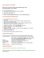
Item checklist (LA-2124A)
We assign LA-2124A hardware support USB interface only,
No external power source require.
1)
2)
3)
4)
5)
The LA-2124A Plastic unit.
Color wires Harness X1 and Easy Hook clips X 30.
LA-2124A User’s Manual X 1.
CD for LA-2124A driver X 1.
USB 2.0 Adapter (mark LA-2124A) with cable (1.0M in length) X 1.
Item Checklist (LA-5000 Series)
1) The LA-5000 Series Aluminum unit.
2) Logic Pod :
X5 (LA-5240, LA-5540), X 10 (LA-5280, LA-5580), X 20 (LA-55160)
3) Color wires and Easy Hook clips:
X50 (LA-5240, LA-5540), X 100 (LA-5280, LA-5580), X 200 (LA-55160)
4) D-Sub 25 Pin Cable 125 CM (Male Ù Female) X 1.
[AWM style 2990 80℃ 30V VW-1 IEEE 1284 compliant]
5) USB 2.0 Adapter with cable (1.5M in length) X 1.
6) DC Power Adapter :
5V/5A X 1 (LA-5240, LA-5280, LA-5540, LA-5580), 5V/10A X 1 (LA-55160)
7) LA-5000 User’s Manual X 1.
8) CD for LA-5000 driver X 1.
9) Pattern Generator Pod (this is optional to order)
System Requirements
In order to use the Logic Analyzer card, the following equipment is necessary:
Computer System:
Pentium PC system with at least one bi-directional mode
(EPP or BPP) or USB interface (USB 1.1 or 2.0 version)
LA-2124A hardware support USB interface only,
Memory:
A minimum of 128 Mega free RAM.
Mass Storage:
At least one CD drives and hard disk drives.
Display Adapter:
At least one of VGA Adapter.
Monitor:
Any monitor compatible with the above display adapter.
Operation System:
Windows 95/98/me/2000/xp.
Installing Hardware
Installing LA-5000 Series parallel port based Logic Analyzer
Please follow these instructions for installing the LA-5000 Series Parallel port based
Logic Analyzers.
3
1) Locate an available parallel port.
2) Connect the included DB-25 cable to parallel port.
3) Connect the other end of the DB-25 cable to the LA-5000 series Logic
Analyzers. (with a DB-25 mini gender changer)
4) Plug the power supply into the an AC outlet.
5) Plug the power supply into the LA-5000 series Logic Analyzers.
Note: for LA-5240, LA-5280, LA-5540, LA-5580 use power supply 5V/5A (Adapter)
for LA-55160 use power supply 5V/10A (Adapter)
6) Connect the pods and wires to the Logic Analyzer. See Installing Pods and Connecting
wires.
7) Make sure the parallel printer port is set to bi-directional mode. This is done in the bios
configuration program of your computer
8) After checking all connections, turn on the computer and peripherals. You are now ready
to install the software.
Installing LA-5000 Series, LA-2124A with USB 2.0 Adapter
Please follow these instructions for installing the LA-5000 Series, LA-2124A Logic Analyzer
With USB 2.0 adapter.
1) Turn off the computer and all peripherals connected. Remove the computer power
cord from the wall outlet. Locate an available USB interface (USB 2.0 adapter cover
USB 1.1 version).
Connect the include USB 2.0 Adapter to the LA5000 Series, LA-2124A parallel port.
2) Connect the included USB cable to USB interface.
3) Connect the other end of the USB cable to the USB 2.0 adapter.
4) Plug the Logic Analyzer power supply into the an AC outlet.
5) Plug the Logic Analyzer power supply into the Logic Analyzer.
6) Connect the pods to the Logic Analyzer.
7) After checking all connections, turn on the computer and peripherals. You are now
ready to install the software.
Note: when LA-2124A connected with USB 2.0 Adapter,
No external power source require.
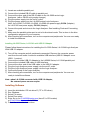
Installing Software
1)
2)
3)
4)
5)
Insert the distribution CD into drive E: ("E" is CD driver)
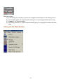
Run Windows.
Select File menu.
Select Run option.
Enter file to run E:\la5000b\setup.exe (here E: is CD location)
or E:\la2124a\setup.exe for la2124a.
6) Follow the on screen instructions.
4
Guide To Operation
Hardware
When making measurements with the Logic Analyzer, meaningful data can only be captured
with some prior knowledge of the characteristics of the circuit under test. Before initiating any
capture cycles, the Logic Analyzer must be configured using the control program. See the
software section later in the manual for instructions on these procedures. To connect the
Logic Analyzer to the test circuit, a series of mini-clips on the Logic Analyzer Pod for the
Logic input channels. The Logic Analyzer Pod has inputs for 40 -160 channels, CH24 – 39
channel is the external clock input. or it has independently external clock for LA-2124A.
At times, it may also be necessary to connect the test circuit to the computer system itself.
This will eliminate more noise in the test application due to ground level differentials. This is
especially true when dealing with high speed timing analysis. Use a heavy gauge wire to
make a connection between the test circuit ground and the case of the computer.
Logic Analyzer Pod Markings
LA-5240-32k
LA-5540-256k
These analyzers have 1 row (Labeled "Board 1") of connectors for 5 pods.
The connectors are labeled 1A, 2A, 3A, 4A and 5A. Connect Pod 1(Ch 0..7),
Pod 2(Ch 8..15), Pod 3(Ch 16..23), Pod 4(Ch 24..31), and pod 5(Ch 32..39) to those connectors.
LA-5280-32k
LA-5580-256k
These analyzers have 2 rows (Labeled "Board 1" and "Board 2") of connectors for 10 pods.
"Board 2" is for channels 40..79
The connectors are labeled 1B, 2B, 3B, 4B and 5B. Connect Pod 1(Ch 0..7),
Pod 2(Ch 8..15), Pod 3(Ch 16..23), Pod 4(Ch 24..31), and pod 5(Ch 32..39) to those connectors.
"Board 1" is for channels 0..39
The connectors are labeled 1A, 2A, 3A, 4A and 5A. Connect Pod 1(Ch 0..7),
Pod 2(Ch 8..15), Pod 3(Ch 16..23), Pod 4(Ch 24..31), and pod 5(Ch 32..39) to those connectors.
LA-55160-256k
This analyzer has 4 rows (Labeled "Board 1", "Board 2", "Board 3" and "Board 4") of connectors
for 20 pods.
"Board 4" is for channels 120..159
The connectors are labeled 1D, 2D, 3D, 4D and 5D. Connect Pod 1(Ch 0..7),
Pod 2(Ch 8..15), Pod 3(Ch 16..23), Pod 4(Ch 24..31), and pod 5(Ch 32..39) to those connectors.
"Board 3" is for channels 80..119
The connectors are labeled 1C, 2C, 3C, 4C and 5C. Connect Pod 1(Ch 0..7), Pod 2(Ch 8..15),
Pod 3(Ch 16..23), Pod 4(Ch 24..31), and pod 5(Ch 32..39) to those connectors.
"Board 2" is for channels 40..79
The connectors are labeled 1B, 2B, 3B, 4B and 5B. Connect Pod 1(Ch 0..7),
Pod 2(Ch 8..15), Pod 3(Ch 16..23), Pod 4(Ch 24..31), and pod 5(Ch 32..39) to those connectors.
5
"Board 1" is for channels 0..39
The connectors are labeled 1A, 2A, 3A, 4A and 5A. Connect Pod 1(Ch 0..7),
Pod 2(Ch 8..15), Pod 3(Ch 16..23), Pod 4(Ch 24..31), and pod 5(Ch 32..39) to those connectors.
Connecting wires to Logic Analyzer
LA-5240-32K
LA-5540-256K
LA-5280-32K
LA-5580-256K
LA-55160-256K
Each pod has 8 channels and 3 ground connections. Each of the grounds is tied together.
push wires onto the posts. Make sure that the wire is actually on the post it is possible to
jam the wire between the post and the plastic case and not make a connection.
The BNC on the back on the Logic Analyzer is a trigger out signal. This pin goes
low when you hit Go and then goes to logic High when the instrument triggers.
LA-2124A-128K
The LA-2124A-128K has 40 pins. They are organized as follows:
Top row:
00..15
Channels 0..15
CLK
External clock input
External trigger out. This pin goes low when you hit Go and then goes to logic High when
the instrument triggers Ground connection.
Bottom row:
16..23
Channels 16..23
NC
Not connected
GND
Ground connection
The wires and the clips that come with the pods are modular. The pods, wires, and clips can
all be disconnected from each other by gently pulling them apart. Removing just the clips, but
leaving the wires connected to the pods allows connections to be made to wires and posts of
the test circuit of up to 0.64 mm (0.025 in).
Do not insert wires or posts greater than this diameter as that will expend the
contacts in the wire beyond the allowed limit, possibly damaging the connector.
6
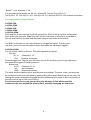
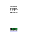
Main Screen
Menu bar
Tool bar
State list
Data is displayed in statelist format in this window.
Timing window
7
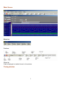
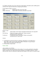
Multi-window
Software open more timing if system free memory have a lot. So use 256 mega or 512
mega memory will be better.
Data1-10 to timing by point User point which timing memory should be placed for
captured data, it can let user captured 2 or 10 set different data to buffer and display, the
sequence pointed by user, this function let user have 128k*10 or 256k*10 memory size.
Data1-10 to timing by auto The same is true for it, it automatically capture 2 or 10 sets
data to buffer, the sequence is 10,9,8,7,6,5,4,3,2 then 1.
Timing1-10<-data Activate timing display. we suggest user use more than 1 monitor to
get better show.
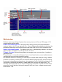
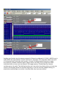
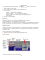
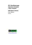
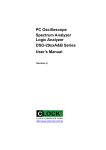
This software is a revolution software, it have a lot of new function, even tradition famous
oscilloscope have not these powerful function.
this software show a lot of timing, let user easy to compare and analyzer timing, tradition
software no matter it is stand alone or computer base oscilloscope only show one timing,
these one timing software only analyzer one segment of buffer, unlike this software it can
look buffer in beginning and buffer in middle and buffer in end at the same time. The
following picture part A show it is locate at beginning and part B at middle of buffer at the
same time, every individual timing also support their own cursor, voltage measurement,
zoom factor .. etc.
8
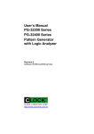
Another new function are let memory expand to10 times by software,LA-2124A, LA5000 now is
128K,256K size, this software can let it look have 1.28 mega, 2.56 mega size when user open
10 timing and set10 timing by auto function. (it need 512 mega system memory or more).
the method is software continue capture data to these 10 timing, every timing have 256k
individual buffer, so user can look almost 2.56 mega memory. it better than any famous
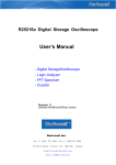
oscilloscope in the world. The third big function are it can show long timing when you have two
monitor, the following show two monitor long timing, it can let user easy analyze timing, so
stand alone oscilloscope can not do it, because they only have one monitor.
9
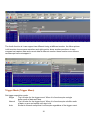
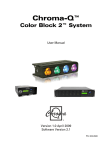
The fourth function is it can support two different timing at different monitor. the follow picture
is left monitor show square waveform and right monitor show another waveform. it easy
compare last capture data and current data at different monitor. these function even famous
oscilloscope have not support it.
Trigger Mode (Trigger Menu)
Set trigger acquisition mode.
Single
The LA looks for the trigger event. When it is found acquire a single
buffer worth of data and stop.
Normal
The LA looks for the trigger event. When it is found acquire a buffer worth
of data, re-arm and repeat until stop is hit.
Auto
Similar to Normal except that it will acquire regardless of the trigger event.
10
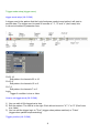
Trigger mode setup (trigger menu)
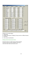
trigger word setup (LA-2124A)
A trigger word is the pattern that the Logic Analyzers needs to see before it will start to
acquire data. The trigger word is made of a series of "1", "0" and "x" (don't care) bits.
It can set at toolbar or parameter form.
Ch23..16
Edit pattern for channels 23 to 16
Ch15..8
Edit pattern for channels 15 to 8
Ch7..0
Edit pattern for channels 7 to 0
Logic
Trigger if condition is true or false.
How to set trigger word (LA-2124A)
1) You can edit all 24 channels at a time.
2) Edit the pattern: The LSB is to the right. Each bit can be set to "X","1" or "0" (Don't care,
true, false)
3) You can set the trigger logic to "True" (trigger when pattern matches) or "False"
(trigger when pattern stops matching)
Trigger position (LA-2124A)
11
The trigger position defines how much data is captured prior to the trigger event and how
much data s stored after it. You set the Trigger position by moving the trigger cursor.
This feature allows you to see the data that led up to the trigger as well as what happened
after the trigger.
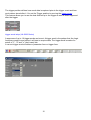
trigger word setup (LA-5000 Series)
A sequence of up to 16 trigger words can be set. A trigger word is the pattern that the Logic
Analyzers needs to see before it will start to acquire data. The trigger word is made of a
series of "1", "0" and "x" (don't care) bits.
It can set trigger word at toolbar or parameter form or trigger form.
12
Channels
Pod 5..1
Condition
Logic
Edit base
Sequence
Count
Select which channel range to edit.
Edit pattern for each pod
Select which word you want to edit.
Trigger if condition is true or false.
Select which base you want to edit in.
Select which word you want to use for each of the 16 levels.
The number of times you want to see the last word in the sequence
before you trigger.
How to set trigger word (LA-5000 Series)
1) The trigger words are edited here:
2) You can edit 40 -160 channels at a time. If your set trigger word at trigger form.
Edit the pattern: The LSB is to the right. Each bit can be set to "X","1" or "0" (Don't care,
true, false)
3) The LA-5000 series Logic Analyzers have 16 level sequential triggering.
4) That means that can specify up to 16 conditions and the Logic Analyzer won't
trigger until all of the conditions have been met in the order specified.
Note: You don't need to use all 16 of the levels and patterns can be repeated. Use the list
boxes to select which condition from the library of trigger patterns you want in each
trigger level. Any level set to "-" will be skipped.
Note: A pattern can be repeated in the sequence.
The last word in the sequence has some extra features:
13
You can look for that pattern "Count" number of times.
5) You can set the trigger logic to "True" (trigger when pattern matches) or "False"
(trigger when pattern stops matching)
Trigger position (LA-5000 Series)
The trigger position defines how much data is captured prior to the trigger event and how
much data s stored after it. You set the Trigger position by moving the trigger cursor. This
feature allows you to see the data that led up to the trigger as well as what happened after
the trigger.
Trigger menu
Go
Stop
End
Start looking for trigger event.
Stop looking for trigger event.
End capture and display data captured up to this point
independent of trigger status.
Trigger word
Define trigger event.
Threshold level
Set threshold level.
Mode
Set trigger mode.
Threshold Voltage Setup
it can set threshold voltage at toolbar or parameter form.
LA-5000 have mode form to set all 40 --160 channels.
14
Set the threshold voltage for one or more pods. Multiple threshold voltages can be set.
Each pod represents 8 channels.
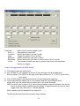
Clock Menu
Select an internal clock rate or an external clock for sampling.
Clock menu for LA-2124A
It can set clock rate at toolbar or parameter form.
100 MHz (10 ns)
Sample on Internal clock.
50 MHz (20 ns)
Sample on Internal clock.
20 MHz (50 ns)
Sample on Internal clock.
10 MHz (100 ns)
Sample on Internal clock.
5 MHz (200 ns)
Sample on Internal clock.
2 MHz (500 ns)
Sample on Internal clock.
1 MHz (1 us)
Sample on Internal clock.
500 KHz (2 us)
Sample on Internal clock.
200 KHz (5 us)
Sample on Internal clock.
100 KHz (10 us)
Sample on Internal clock.
50 KHz (20 us)
Sample on Internal clock.
20 KHz (50 us)
Sample on Internal clock.
10 KHz (100 us)
Sample on Internal clock.
5 KHz (200 us)
Sample on Internal clock.
Note: The software only transfers data to the PC when the buffer is full. If you are
using a slow clock it might take a long time to fill the buffer.
Recording time/Acquisition time/Capture time/Buffer Length
15
The Logic analyzer will acquire data for time equal to Buffer length * clock rate.
Example:
If buffer length = 128K and sample rate = 100KHz. The LA will record for 1.32
seconds (128K * 10 us).
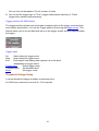
Clock menu for la-5540-256k, la-5580-256k and la-55160-256k
It can set clock rate at toolbar or parameter form.
500 MHz (2 ns) Pod 1*,3*,5* is at 500MHz, Pod 2*, 4* are off
250 MHz (4 ns)
100 MHz (10 ns)
50 MHz (20 ns)
20 MHz (50 ns)
10 MHz (100 us)
5 MHz (200 us)
2 MHz (500 us)
1 MHz (1 us)
500 KHz (2 us)
200 KHz (5 us)
100 KHz (10 us)
50 KHz (20 us)
20 KHz (50 us)
10 KHz (100 us)
5 KHz (200 us)
2 KHz (500 us)
1 KHz (1 ms)
500 Hz (2 ms)
200 Hz (5 ms)
100 Hz (10 ms)
50 Hz (20 ms)
20 Hz (50 ms)
10 Hz (100 ms)
5 Hz (200 ms)
2 Hz (500 ms)
1 Hz (1 s)
All Pods active.
All Pods active.
All Pods active.
All Pods active.
All Pods active.
All Pods active.
All Pods active.
All Pods active.
All Pods active.
All Pods active.
All Pods active.
All Pods active.
All Pods active.
All Pods active.
All Pods active.
All Pods active.
All Pods active.
All Pods active.
All Pods active.
All Pods active.
All Pods active.
All Pods active.
All Pods active.
All Pods active.
All Pods active.
All Pods active.
Pattern Generator functions are not available at 250MHz and 500MHz modes.
Note: The software only transfers data to the PC when the buffer is full. If you are
using a slow clock it might take a long time to fill the buffer.
Recording time/Acquisition time/Capture time/Buffer Length
The Logic analyzer will acquire data for time equal to Buffer length * clock rate.
16
Example
If buffer length = 8K and sample rate = 1KHz. The LA will record for 8.096 seconds
(8K * 1ms).
External clock (LA-2124A)
External clock setup. The LA has up to 1 external clock input. This input can be set to rising
or falling. The LA will acquire 1 sample every time it sees a clock.
Note 1: The LA only transfers data to the PC after the data buffer is full. Slow external
clocks might take a very long time to fill the buffer.
Note 2: Make sure that your external clock has enough pulses to fill the buffer or the
instrument will never transfer data.
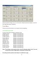
External clock (LA-5000 Series)
External clock setup. The LA has up to 8 external clock inputs. These inputs can be
combined to create very complex clocking. Pod 5A is used for the external clock.
Note:
The LA only transfers data to the PC after it has received a full buffer worth of
data. If your clock is very slow it might take a long time to fill the buffer. Please
make sure your clock happens enough times to fill the buffer.
17
1..16
Logic
16 sets of 8 bit patterns that are OR's together to form a complex clock.
Each bit can be set to 0, 1 or X.
Clock on the rising or falling edge.
Modes::
Normal
External clock
Latched 100MHz
Clock on external + 100MHz internal to avoid too narrow waveform to
make circuit crazy.
Rising and falling
Clock on the rising and the falling edge of the external clock.
Logic:
Logic rising
Logic falling
Clock on the external rising edge.
Clock on the external falling edge.
How to use:
18
1) Each word represents the 8 external clocks
Each bit can be set to
0(low), 1(high) or X (don't care).
2) The 16 words are OR's together to form a complex clock.
3) Set clock mode:
Normal
Sample on the external clock.
Internal + external
Mix of internal + external clock.
Rising and falling Clock on the rising or the falling edge of the
external clock.
4) Set Logic to rising or falling.
Examples:
Example 1: Pattern 1 = xxx1xxx0 and all other patterns are xxxxxxxx
Result: Sample when line 4 is HIGH and line 0 is LOW.
Example 2: Pattern 1 = xxx1xxx0, Pattern 2 = xxxx xx11 and all other patterns are xxxxxxxx
Result: Sample when line 4 is HIGH and line 0 is LOW or when Lines 1 and 0 are HIGH.
Magnify (timing)
Select a zoom ratio for the timing window. You can display the timing data in a compressed
or expanded format. Zooming in lets you see great detail. Zooming out lets you see large
abundant of data.
Zoom can be changed in the following ways:
1) Right clicking on the combo brings up a magnify factor list.
Zoom Combo
In the timing window you can do the following:
19
Zoom
Zoom in or out by selecting zoom factor combo.
Window to cursor A:
Zoom around cursor A
Window to cursor B:
Zoom around cursor B
Window to cursor T:
Zoom around cursor T (trigger cursor)
cursor A to Window:
shift cursor A to window
cursor B to Window:
shift cursor B to window
cursor T to Window:
shift cursor T to window
cursor A, B, T to Window:
shift cursor A, B, T to window
Timing window
This window shows the data in a timing waveform style display. The channel names
will be on the left edge with the data going horizontally. To the right of the channel
names are the values of data at each cursor (it is color coded to match the cursors).
The vertical scrollbar moves the window up and down to display more channels. The
horizontal scrollbar moves the data forward and backward in time.
The channel order can be changed by the color form.
The size of the window can be changed by grabbing an edge of the window and dragging it.
When the Timing window is selected (title says "active window")
Left and right arrows scroll data with respect to time,
or grabbing timing to shift data.
Up and down arrows scroll data with respect to channels.
Window to cursor A:
Zoom around cursor A
Window to cursor B:
Zoom around cursor B
Window to cursor T:
Zoom around cursor T ( trigger cursor)
cursor A to Window:
shift cursor A to window
cursor B to Window:
shift cursor B to window
cursor T to Window:
shift cursor T to window
cursor A, B, T to Window:
shift cursor A, B, T to window
Note:
This only works on the selected window.
Click on the window to select it.
Cursor using
Cursors are used to mark points of interest in the data, to measure time between events
and to define pre/post trigger position.
20
Moving a cursor:
1) In the timing you can select a cursor by using the arrow buttons in the timing move it.
2) You can also "grab" the cursor by left clicking on it in the timing and then move it by
3) "dragging" it to a new location.
4) The timing cursor A, B, T have selections that allow you to bring the cursors onto their
views.
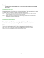
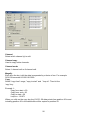
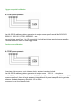
Setting Up The State Window
21
Setting up the state display.
1) Set group
2) Select which group to display. Groups can be in different bases.
3) Set Base.
4) Set channel combination.
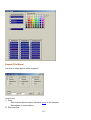
Setting channel names and colors
Channel names can edit at timing window directly.
Channel names should be edited at color form.
Color form also can set all cursor color.
22
Export (File Menu)
Use this to output data to other programs.
How to use:
1) Data:
Select which data to output: Individual group or all channels
Select base to output data in.
2) Start and End:
23
Select data address range.
3) Click OK to save data.
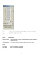
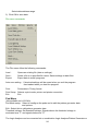
File menu commands
The File menu offers the following commands:
Load :
Save :
Export:
Opens an existing file (data or settings).
Saves a file to a specified file name. Saves settings or data files.
Export data to excell programs.
Auto save setting : If checked settings will be saved when you exit the program.
then loaded when you load the program.
Print:
Prints data in Timing format.
Print Setup: Selects a print mode, printer and printer connection.
Exit:
Exit.
Pod Menu
(Not available on LA-2124A)
Pod Mode setup: Select to configure the pods and to edit the pattern generator data
and options.
Edit : Select this to edit pattern generator data.
Threshold voltage: Set threshold voltage. Signals above the threshold voltage is
evaluated as a "1" and signals below are "0".
The Logic Analyzer can be converted into a combination Logic Analyzer/Pattern Generator or
24
to a Pattern Generator only. This is done by buying Pattern Generator pods, installing them
instead of the Logic pods and then configuring the software.
Three different modes can be set
Logic
Install Logic pods and acquire data.
Pattern Generator
Install Pattern Generator pods and output data.
Pattern mode:
Once
Out until trig
Continuous
Output pattern once. Data is acquired simultaneously on Logic pods.
Output until trigger condition met. Data is acquired
simultaneously on Logic pods.
Continuously output until stop hit. Data is not acquired
simultaneously on Logic pods.
How to:
1) Install pattern pods and select the matching configuration on the table above.
Note: Pods 1 and 2 must be both either Pattern Generator or Logic Analyzer.
Pods 3 and 4 must also be the same type.
2) Select pattern output mode.
Pattern editor
(Not available on LA-2124A)
Patterns can be edited and defined in this window. You can also get data for the pattern
data by capturing it from logic channels and copying it to the pattern channels. Pattern
data can also come from data files created by this software or files that you create yourself.
25
Channel
Select which channel (s) to edit.
Channel copy
Used to copy entire channels.
Channel mode
Select 1 channel edit or 8 channel edit.
Magnify
Each time the key is hit the data is expanded by a factor of two. For example
0101100 becomes 00110011110000
Copy
Select "copy from" range, "copy to start" and "loop to". Then hit the
'copy' key.
Example 1:
Copy from start = 20
Copy from end = 30
Copy to start = 50
Loop to = 131071
When you click on the copy key the 131071-50 data points from position 20 to and
including position 30 in the data buffer will be copied to position 50.
26
Accessories
Pattern generator pods (Not available for the LA-2124A)
Pattern generator pods can be purchased to convert the LA-5000 Series into a pattern
generator. the mini DB-25 gender changer connect to LA-5000 Series, it is parallel port
based Logic Analyzers.
USB 2.0 adapter
An optional USB adapter is available for the LA-5000 series, LA-2124A Logic Analyzers.
It allows you to run the Analyzer from the USB port of your computer instead of the ISA
Hardware / Software Specifications
Note: From the date of September 2002 we do not supply the ISA bus for
LA-5000 Series Logic Analyzer.
Software (LA-5000 series)
Operating systems supported.
WIN 95/98/ME :
Yes.
WIN 2000/XP/Vista :
Yes. (connect USB 2.0 Adapter only)
Software (LA-2124A)
Operating systems supported
WIN 95/98/ME:
Yes.
WIN 2000/XP:
Yes. (connect USB 2.0 Adapter only).
Memory Modes And Channel Specs
Memory mode
Select memory mode:
Available Channels
LA-2124A-128K
Max speed channels (memory size)
up to 50MHz external 24 (24 @ 128K each) All channels available
up to 100MHz internal 24 (24 @ 128K each) All channels available
(up to 160MHz internal 24 (24 @ 128K each) All channels available when purchase after August 2005)
LA-5240-32K
Max speed channels (memory size)
up to 50MHz external 40 (40 @32K each) All channels available
up to 100MHz internal 40 (40 @32K each) All channels available
100MHz 40 (40 @100MHZ @32K)
200MHz 24 (24 @200MHZ @64K) Pods 1a, 2a are at 200MHz, Pods 3a, 4a are off.
Pods 5a are at 100MHz.
27
LA-5540-256K
Max speed channels (memory size).
up to 80MHz external 40 (40 @128K each) All channels available.
up to 250MHz internal 40 (40 @256K each) All channels available.
500MHz 24 (24 @500MHZ @512K) Pods 1a, 3a, 5a are at 500MHz, Pods 2a, 4a are off.
LA-5280-32K
Max speed channels (memory size)
up to 50MHz external 80 (80 @32K each) All channels available.
up to 100MHz internal 80 (80 @32K each) All channels available.
100MHz 80 (80 @100MHz @32K).
200MHz 48 (48 @200MHz @32K) Pods 1a, 2a & 1b, 2b, are at 200MHz.
Pods 3a, 4a & 3b, 4b are off. Pods 5a & 5b are at 100MHz.
LA-5580-256K
Max speed channels (memory size)
up to 80MHz external 80 (80 @ 128K each) All channels available
up to 250MHz internal 80 (80 @ 256K each) All channels available
500MHz 48 (48 @500MHz @512K) Pods 1a, 3a, 5a & 1b, 3b, 5b are at 500MHz,
Pods 2a, 4a & 2b, 4b are off.
LA-55160-256K
Max speed channels (memory size)
up to 80MHz external 160 (160 @ 128K each) All channels available
up to 250MHz internal 160 (160 @ 256K each) All channels available
500MHz 96 (96 @500MHZ @512K) Pods 1a, 3a, 5a 1b, 3b, 5b, 1c, 3c, 5c & 1d, 3d, 5d are
at 500MHz, Pods 2a, 4a, 2b, 4b, 2c, 4c, & 2d, 4d are off.
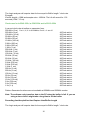
Window USB Driver Install
Windows 98/ME USB driver install
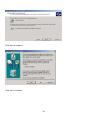
When USB2.0 control interface be connected to computer, screen will display
28
Click Next to continue
Edit or browse path to ...\USB20driver\win98_ME\gene.inf
(here D: is CD location, dso25216A may be dso29xx or la5000b or la2124a)
Click Next to continue
29
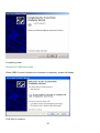
Click Next to continue
Completing install
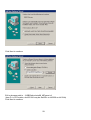
Windows 2000 USB driver install
When USB2.0 control interface be connected to computer, screen will display
30
Click Next to continue
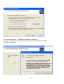
Click Next to continue
31
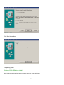
Click Next to continue
Edit or browse path to ...\USB20driver\win2000_XP\gene.inf
(here F: is CD location, dso25216A may be dso29xx or la5000b or la2124a)
Press OK
32
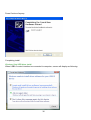
Click Next to continue
Click Yes to continue
33
Completing install
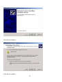
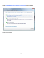
Windows XP USB driver install
When USB2.0 control interface be connected to computer, screen will display
Click Next to continue
34
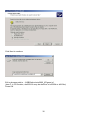
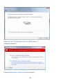
Edit or browse path to ...\USB20driver\win2000_XP\gene.inf
(here E: is CD location, dso25216A may be dso29xx or la5000b or la2124a)
Click Next to continue
35
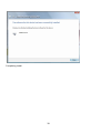
Press Continue Anyway
Completing install
Windows Vista USB driver install
When USB2.0 control interface be connected to computer, screen will display as following:
36
Press Locate and install driver software (recommended) Continue Anyway
Press Continue Anyway
37
Press Insert the disc that came with your USB2.0 Device
Click Next to continue
Press Install this driver software anyway to Continue
38
Completing install
39
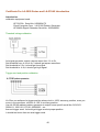
Certificate For LA-5000 Series and LA-2124A Introduction
Introduction
calibration equipment used:
HP 33120A Serial No: US36034172
Clock Computer Corp. LA-55160 Pattern Generator
HP 8648A Signal Generator Serial No: 3625U00521
Threshold voltage calibration
Let signal generator output a square wave from -5v to 5v.
Set threshold from -4.8 to 4.8v, it should get square waveform.
Set threshold to 5.2v, it should get low signal.
Set threshold to -4.8v, it should get high signal.
Trigger word and position calibration
LA-55xx use software let trigger position always lock in 100% accuracy position, even you
zoom in the waveform, still lock in 100 % accuracy position.
Use LA-55160 arbitrary pattern generator to output some specific word like 01010101
00001111 10001101 1111111 00000000... etc.
then set trigger word. it should get trigger word at proper position.
it should test more than ten sets trigger word.
40
Trigger sequential calibration
Use LA-55160 arbitrary pattern generator to output some specific word like 01010101
00001111 10001101 1111111 00000000... etc.
then set trigger word from 1 to 15 sequential. it should get trigger word at proper position.
it should test more than ten sets trigger word.
Clock source calibration
It has two clock source, one is internal clock, another is external clock.
Use LA-55160 arbitrary pattern generator to output some 1/2 1/4 ... etc pattern .
the LA-55160 output sample rate is 1 to 100 MHz, for 1/2 pattern, it can get 1/2 Hz to 50 MHz
square wave form. then set logic analyzer internal clock to proper sample rate to get data,
measure the data frequency should be 1/2 to 50mh.
the same is true for external clock.
41
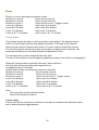
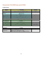
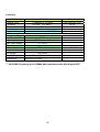
Characteristic Of LA-5000 Series and LA-2124A
LA-5000 Series:
Model
External Clock
Frequency
Memory
Channel
Trigger Level
Trigger Qualify
Pattern Generator
Threshold Voltage
Input Bandwidth
Input Impedance
Max. Input Voltage
Power Supply
PC Interface
Net Weight
Size (Dimension)
Accessories
LA-55160
8 Channels 0 - 80 MHz
500 MHz 96Ch 1Hz~250MHz160Ch
512 K/96 Ch
256 K/160 Ch
160 Channels
16 Levels 160 Ch Complex
8 Channels
0 ~ 50 MHz (0 ~ 100 MHz Rate)
12 Sets -6.4v ~ +6.4v
100 MHz
200 Kohm ≦ 5pF
± 150 V
DC Adapter 5V/10A
Parallel port / USB 1.1 / 2.0
4.0 Kgs
210mm x 215mm x 95mm
Logic pod, USB 2.0 Adapter, User’s Manual,
Software driver, Color wires + clips,
Parallel cable (IEEE1284), DC Adapter 5V/10A.
42
Remark
From Channel D32~39
160Ch
Logic Pod
Optional to order
Universal Input
EPP / BPP
Aluminum Case
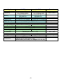
Model
External Clock
Frequency
Memory
Channel
Trigger Level
Trigger Qualify
Pattern Generator
Threshold Voltage
Input Bandwidth
Input Impedance
Max. Input Voltage
Power Supply
PC Interface
Net Weight
Size (Dimension)
Accessories
LA-5580
LA-5540
Remark
8 Channels 0 - 80 MHz
From Channel D32~39
500 MHz 48Ch
500 MHz 24Ch
80Ch /40Ch
1 Hz~250MHz 80Ch
1 Hz~250MHz 40Ch
512 K/48 Ch
512 K/24 Ch
256 K/80 Ch
256 K/40 Ch
80 Channels
40 Channels
Logic Pod
16 Levels 80 Ch Complex 16 Levels 40 Ch Complex
8 Channels
0 ~ 50 MHz (0 ~ 100 MHz Rate)
Optional to order
6 Sets -6.4v ~ +6..4v
3 Sets -6.4v ~ +6.4v
100 MHz
200 Kohm ≦ 5pF
± 150 V
DC Adapter 5V/5A
DC Adapter 5V/2.5A
Parallel port / USB 1.1 / 2.0
2.5 Kgs
1.8 Kgs
210mm x 215mm x 70mm
Logic pod, USB 2.0 Adapter, User’s Manual,
Software driver, Color wires + clips,
Parallel cable (IEEE1284), DC Adapter 5V/2.5A (5A).
43
Universal Input
EPP / BPP
Aluminum Case
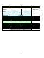
Model
External Clock
Frequency
Memory
Channel
Trigger Level
LA-5280
LA-5240
8 Channels 0 - 80 MHz
From Channel D32~39
200MHz+100MHz/32Ch+16Ch 200MHz+100MHz/32Ch+16Ch
100MHz/80Ch
100MHz/80Ch
80Ch / 40Ch
64 K / 32 Ch+ 16 Ch
32 K / 80 Ch
80 Channels
64 K / 16 Ch+ 8 Ch
32 K / 40 Ch
40 Channels
8 Channels
0 ~ 50 MHz (0 ~ 100 MHz Rate)
Threshold Voltage
Input Bandwidth
Input Impedance
6 Sets -6.4v ~ +6.4v
3 Sets -6.4v ~ +6.4v
100 MHz
200 Kohm ≦ 5pF
Max. Input Voltage
Power Supply
PC Interface
± 150 V
DC Adapter 5 V/5A
DC Adapter 5 V/2.5A
Parallel port / USB 1.1 / 2.0
Accessories
Logic Pod
16 Levels 80 Ch Complex 16 Levels 40 Ch Complex
Trigger Qualify
Pattern Generator
Net Weight
Size (Dimension)
Remark
2.5 Kgs
1.8 Kgs
210mm x 215mm x7 0mm
Logic pod, USB 2.0 Adapter, User’s Manual,
Software driver, Color wires + clips,
Parallel cable (IEEE1284), DC Adapter 5V/2.5A (5A).
44
Optional to order
Universal Input
EPP / BPP
Aluminum Case
LA-2124A:
Model
External clock
Frequency ***
Memory
Channel
Trigger Level
LA-2124A
1 Channels 0 - 80 MHz
12.5 KHz ~ 160 MHz ***
128 K
24 Channels
1 Levels 24 Channels "0", "1", "X"
Threshold Voltage
Input Bandwidth
Input Impedance
Max. input voltage
Power Supply
PC Interface
-1v ~ +3v
30 MHz
50 Kohm ≦ 5pF
-5 ~ +10 V
No external power source require
USB 1.1 / 2.0
Net Weight
Size (Dimension)
120 Grams
150mm x 70mm x 25mm
Accessories
Remark
From Channel "CLK"
24 Ch
24 Ch
Power Supply by USB
Color wires + clips, USB 2.0 Adapter + cable
User's Manual, CD driver
*** LA-2124A Frequency up to 160MHz when purchase order after August 2005
45
Technical Support
Technical Support can be reached at
克拉克電腦股份有限公司
7F., No: 5. Lane 236, Section 5.
Roosevelt Road. Taipei, 116. Taiwan.
Phone: 886-2-29321685. 29340273. 29335954.
Fax: 886-2-29331687.
Email: [email protected]
Software Updates
Software can be downloaded from our website
http://www.clock-link.com.tw
Software ®copyright
7/F., No: 5. Lane 236, Section 5.
Roosevelt Road. Taipei, 116. Taiwan.
All Right Reserved
Phone: 886-2-29321685. 29340273. 29335954.
Fax: 886-2-29331687.
E-mail: [email protected]
46