1
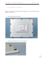
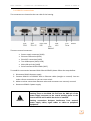
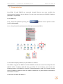
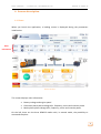
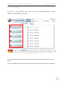
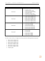
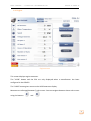
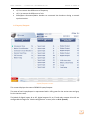
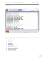
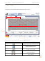
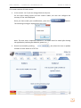
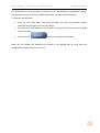
RDM 3.0 User manual – technical documentation A53 V0 9 0020 A User manual – technical documentation A53V0 9 0020 A Technical documentation history Date September 2015 Version A Comment Initial edition 2 User manual – technical documentation A53V0 9 0020 A Content 1. Presentation........................................................................................................................................5 2. Installation ..........................................................................................................................................5 2.1 Environment ............................................................................................................................................................. 6 2.3 Unpacking .................................................................................................................................................................. 6 2.5 Installation in the control cabinet ................................................................................................................. 8 2.2 2.4 3. 4. 2.6 RDM 3.0 connections......................................................................................................................................... 10 Animated symbols .......................................................................................................................... 13 4.1 Generator ................................................................................................................................................................ 13 4.3 Mains ......................................................................................................................................................................... 14 4.4 4.5 4.6 4.7 Load ............................................................................................................................................................................ 13 Bus bar ...................................................................................................................................................................... 14 Breakers ................................................................................................................................................................... 15 Connections............................................................................................................................................................ 15 Logical indicators ................................................................................................................................................ 15 Navigation bar and header........................................................................................................... 16 5.1 6. Preparation ............................................................................................................................................................... 7 Communication ............................................................................................................................... 11 4.2 5. Transport ................................................................................................................................................................... 6 5.2 Navigation bar ...................................................................................................................................................... 16 Header....................................................................................................................................................................... 17 Screens description........................................................................................................................ 18 6.1 Home.......................................................................................................................................................................... 18 6.3 Generator/Mains/Bus ...................................................................................................................................... 23 6.2 6.4 Power plant ............................................................................................................................................................ 21 Engine ....................................................................................................................................................................... 25 6.5 Synchro..................................................................................................................................................................... 26 6.7 Temporizations .................................................................................................................................................... 28 6.6 6.8 6.9 6.10 6.11 6.12 6.13 Inputs/Outputs .................................................................................................................................................... 27 Maintenance .......................................................................................................................................................... 29 Events........................................................................................................................................................................ 30 Curves ....................................................................................................................................................................... 31 System....................................................................................................................................................................... 33 Information ............................................................................................................................................................ 37 Alarms/Faults ....................................................................................................................................................... 39 3 User manual – technical documentation A53V0 9 0020 A 7. Technical specifications ............................................................................................................... 41 8. Dimensions ....................................................................................................................................... 42 4 User manual – technical documentation A53V0 9 0020 A 1. Presentation RDM 3.0 is a color touch screen remote display module that supplements GENSYS 2.0 CORE, to control a single generating sets power in a power plant. Connected to a GENSYS 2.0 or GENSYS 2.0 LT, RDM 3.0 module can be used as an additional remote display. Information displayed: • • • • • • • • • • Synoptic of the installation Power plant overview Generator and mains/bus electrical measures : Phase-phase voltage (3 phases RMS) Phase-neutral voltage (3 phases RMS) Current (3 phases RMS) Frequency Active power (3 phases + total) Reactive power(3 phases + total) Power factor (3 phases+ total) Active energy (kWh) Reactive energy (kVARh) Engine measures: oil pressure, water temperature, engine speed, hours run meter, spare analog inputs, J1939 measures. Synchronization conditions GENSYS inputs/outputs (ON/OFF) Active timers Maintenance cycle monitoring Alarms & faults and events Information screen 2. Installation Warning The GENSYS firmware version must be at least v4.66a5 to ensure the proper functioning of the HMI. 5 User manual – technical documentation A53V0 9 0020 A 2.1 Environment Operating temperature: 0° to +55°C Storage temperature: -25° to +65°C Humidity: to 95%, no condensation 2.2 Transport Despite the robust design of the unit, the components are sensitive to strong vibrations and impacts. During transport, your device should therefore be protected from excessive mechanical stress. Danger of damage to the unit : Warning If the device is transported in cold weather or is exposed to extreme variations in temperature, make sure that moisture (condensation) does not form on or inside the device. 2.3 Unpacking • Make sure the package contains the RDM 3.0 with the alimentation connector plugged. • Keep the package in case of return. • Ensure that there are no visible defects on the device 6 User manual – technical documentation A53V0 9 0020 A 2.4 Preparation Circulation of air : When the unit is installed in an enclosure, adequate space for ventilation must be provided. Note • • • • • The clearance above and below the housing must be at least 5 cm in order to ensure adequate ventilation of RDM 3.0. Control cabinet cutting : 247.5x298mm (9.74x11.73 inch) Position RDM 3.0 in such a way that reflections on the screen are avoided as much as possible Use the position of the screen as a guide for the correct installation height; it should be optimally visible for the user at all times The panel PC should not be exposed to direct sunlight When the unit is in its mounting position, the ventilation openings must not be obstructed. Warning Control cabinet cutting : The cutting dimensions must be respected. A torsion of the screen can cause a malfunction of the device Avoid extreme environment : Extreme environmental conditions should be avoided as much as possible. Protect RDM 3.0 from dust, moisture and heat. The ventilation slots of the device must not be covered. Risk of explosion! RDM 3.0 must not be used where there is a risk of explosion. Danger 7 User manual – technical documentation A53V0 9 0020 A 2.5 Installation in the control cabinet RDM 3.0 is installed in the cabinet wall with clamping levers. The wall thickness must be between 1 mm and 5 mm. 1. Insert the RDM 3.0 into the cutout. 2. Release the clamping levers with a 3.0 mm Allen key. 8 User manual – technical documentation A53V0 9 0020 A 3. Turn the clamping levers to the side through 90°. 4. Retighten the screws. 9 User manual – technical documentation A53V0 9 0020 A 2.6 RDM 3.0 connections The connectors are located at the rear side of the housing. There are several connectors: • • • • • • Power supply connector (X101) Ethernet connection (X102) EtherCAT connection (X103) Two USB outputs (X104, X105) Micro-SD card slot (X106) Serial interface RS232 COM1 (X107) To establish a connection between RDM 3.0 and GENSYS please follow the steps bellow: 1- Disconnect RDM 3.0 power supply 2- Connect RDM 3.0 to GENSYS with an Ethernet cable (straight or crossed). You can make a direct connection or you can use a switch 3- Make sure that connections between wires and connectors are correctly secured 4- Reconnect RDM 3.0 power supply Attention Don't forget to establish a low-impedance connection from the earthing point on the RDM 3.0 and from the GND pin of the power supply connector to the central earthing point on the control cabinel wall in which the device is installed. Earthing connections dissipate interference from external power supply cables, signal cables or cables to peripheral equipment. 10 User manual – technical documentation A53V0 9 0020 A 3. Communication Once RDM 3.0 and GENSYS are connected through Ethernet, you must establish the communication between the two devices. For that, you must know your GENSYS IP address (192.168.11.1 by default). On the RDM 3.0: Firstly, leave the application pressing the (refer to 6.11 System) button of the “System” screen Go in « Start/Control Panel /Network and Dial-up Connections/FEC1» In the window displayed below, key the RDM 3.0 IP address. The address range of the RDM 3.0 and the GENSYS must be the same: For example for the GENSYS default IP address (192.168.11.1), give RDM 3.0 an IP address that matches the following pattern: 192.168.11.XX (with XX included between 0 and 255). Ensure that the chosen IP address is different from the GENSYS IP address or any other devices connected to the Ethernet network. In that case we chose 192.168.11.2 11 User manual – technical documentation A53V0 9 0020 A Subnet mask is 255.255.255.0 Push . Note: If all devices are connected to a network with DHCP server, you can select the option "Obtain an IP address via DHCP". This option will automatically give RDM 3.0 an IP address compatible with the network. Once the IP address is configured, press "Start" and then "Reset" to reset the RDM 3.0 and start the application. To finalize the communication, you must configure in the application the IP address of the GENSYS you want to communicate with (refer to 6.11 System). 12 User manual – technical documentation A53V0 9 0020 A 4. Animated symbols The application contains several animated symbols 4.1 Generator Symbol Description Generator is idle Generator is running 4.2 Load Symbol Description Load isn't supplied Load is supplied 13 User manual – technical documentation A53V0 9 0020 A 4.3 Mains Symbol Description Mains is missing Mains is present 4.4 Bus bar Symbol Description Bus bar isn't supplied Bus bar is supplied 14 User manual – technical documentation A53V0 9 0020 A 4.5 Breakers Symbol Description Breaker is open Breaker is closed 4.6 Connections Symbol Description Currentless wire Live wire 4.7 Logical indicators Symbol Description This symbol show the state of a Boolean variable: Grey = OFF Green= ON Grey: manual mode not selected Orange: manual mode selected Grey: automatic mode not selected Blue: automatic mode selected Grey: test mode not selected Orange: test mode selected 15 User manual – technical documentation A53V0 9 0020 A 5. Navigation bar and header 5.1 Navigation bar RDM 3.0 contains a navigation bar allowing you to navigate between the different screens of the application. Symbol Description Home screen Power plant overview (for several generators) Generator electrical measures Mains electrical measures (1 generator + 1 Mains) Bus bar electrical measures (multi-generator plant) Engine measures (water temperature, oil pressure…) Synchronization information Inputs/outpus states Generator active temporisation Maintenance cycle 16 User manual – technical documentation A53V0 9 0020 A Symbol Description Events screen Evolution curves of the selected data RDM 3.0 settings Information and modification by parameter number Blinking when a fault appears. Press button to display Fault screen Blinking when an alarm appears. Press button to display Alarm screen 5.2 Header The header is present in all screens of the application. This one gives users the following information: 1. 2. 3. 4. Screen currently displayed Plant state Engine state Date and time (synchronized with GENSYS time) 17 User manual – technical documentation A53V0 9 0020 A 6. Screens description 6.1 Home When you launch the application, a loading screen is displayed during the parameters initialization. Main information Home screen This screen displays main information: • • • Battery voltage and engine speed Generator phase-phase voltage U31, frequency, active and reactive power Mains phase-phase voltage U31, frequency, active and reactive power On the left, there are the three GENSYS modes with, in manual mode, the possibility to command the plant: 18 User manual – technical documentation Button A53V0 9 0020 A Description Start the generator's engine. Visible when the generator is idle. Stop the generator's engine. Visible when the generator is running. Increase the engine speed (F)/the alternator voltage (U). Decrease the engine alternator voltage (U). speed (F)/the Close the generator/Mains breaker. Visible when the breaker is open. Open the generator/Mains breaker. Visible when the breaker is closed. In "AUTO" and "TEST" mode, buttons described above are disabled. An animated synoptic is displayed to inform the user about the plant state (refer to 4 Animated symbols). 19 User manual – technical documentation A53V0 9 0020 A There are two possible synoptics according to the GENSYS configuration: This one is displayed for a "One generator and one mains" configuration (parameter "Quantity of GENSYS"= 1 in the GENSYS) This one is displayed for a "Several generators" configuration (parameter "Quantity of GENSYS">1 in the GENSYS) 20 User manual – technical documentation A53V0 9 0020 A 6.2 Power plant This screen is only available when there are several GENSYS (parameter "Quantity GENSYS">1 in the GENSYS connected) Power plant overview screen This screen consists of several screens with the same structure and described in the table below. You can navigate between them thanks to the buttons located on the left side of the screen. 21 User manual – technical documentation Screen Plant states (4 screens) GE 01 to 32 – kW (2 screens) GE 01 to 32 - kVAR (2 screens) GE 01 to 32 – kW - Nom (2 screens) GE 01 to 32 – kVAR - Nom (2 screens) A53V0 9 0020 A Description Status of the generators constituting the power plant Active power production (In % of the nominal active power) of each generator constituting the power plant Reactive power production (In % of the nominal reactive power) of each generator constituting the power plant Nominal active power of each generator constituting the power plant Nominal Reactive power of each generator constituting the power plant Each screen consists of several sub screens allowing the display of the information above for a maximum of 32 generators (8 generators by sub screen for "Plant states" screen and 16 generators by sub screen for the others). You can navigate between these sub screens using the buttons and . The number of generators displayed matches the quantity of GENSYS configured in the GENSYS connected to the RDM 3.0. Information related to the connected GENSYS is displayed in green. 22 User manual – technical documentation A53V0 9 0020 A 6.3 Generator/Mains/Bus Generator electrical measures 1/4 screen The "Generator" and "Mains" screens structure is identical. They consist of 4 sub screens which include the electrical measures described in the table below. You can navigate between these sub screens using the buttons and . 23 User manual – technical documentation Screen Screen 1/4 Screen 2/4 Screen 3/4 Screen 4/4 A53V0 9 0020 A • • • • • • • • • • • • • • • • • • • • • • • • • Displayed measures Phase-phase voltage U31 (V) Frequency (Hz) Total active power (kW) Total reactive power (kVAR) Total power factor Total active energy (kWh) Total reactive energy (kVARh) Phase-neutral voltage V1 (V) Phase-neutral voltage V2 (V) Phase-neutral voltage V3 (V) Phase-phase voltage U12 (V) Phase-phase voltage U23 (V) Phase-phase voltage U31 (V) Active power P1 (kW) Active power P2 (kW) Active power P3 (kW) Reactive power Q1 (kVAR) Reactive power Q2 (kVAR) Reactive power Q3 (kVAR) Current I1 (A) Current I2 (A) Current I3 (A) Power factor cos(φ1) Power factor cos(φ2) Power factor cos(φ3) The "Bus" screen consists of a single screen that contains the following electrical measures • • • • • • • Phase-neutral voltage V1 (V) Phase-neutral voltage V2 (V) Phase-neutral voltage V3 (V) Phase-phase voltage U12 (V) Phase-phase voltage U23 (V) Phase-phase voltage U31 (V) Frequency (Hz) 24 User manual – technical documentation A53V0 9 0020 A 6.4 Engine Engine screen This screen displays engine measures. The "J1939" button and the ECU are only displayed when a manufacturer has been configured in the GENSYS. The "J1939" button gives access to the J1939 measures display. Measures are allocated between 7 sub screens. You can navigate between these sub screens using the buttons and . 25 User manual – technical documentation A53V0 9 0020 A 6.5 Synchro Synchronization screen This screen displays the information needed to synchronize the generator with the mains or with the bus bar. The user can see the synchronization conditions: • • • • Difference of volt between mains/bus and generator Difference of frequency between mains/bus and generator Difference of phase between mains/bus and generator Phase sequence The conditions states are represented by LEDs: green if the condition is true, red if the condition is false. The difference of frequency and volt are measured and displayed as graduated ruler. At the bottom of the screen, we find the same synoptic as in the home screen allowing the user to have an overview of the plant during the synchronization. We also find the following buttons: 26 User manual – technical documentation • • • A53V0 9 0020 A +F/-F to correct the difference of frequency +U/-U to correct de difference of volt Close/Open Generator/Mains breaker to command the breakers during a manual synchronization. 6.6 Inputs/Outputs Inputs/Outputs screen This screen displays the states of GENSYS inputs/outputs. The state of each input/output is represented with a LED: green for the active state and grey for the inactive state. The labels of digital inputs J4 to J15, digital outputs C1 to C5 and relay outputs A1 to A2 are configurable through the "Labels configuration" screen (refer to 6.11 System). 27 User manual – technical documentation A53V0 9 0020 A 6.7 Timers Timers screen This screen displays GENSYS active timers which are divided between two sub screens. To navigate between the sub screens, use the tabs at the top of the screen (boxed in red). 28 User manual – technical documentation A53V0 9 0020 A 6.8 Maintenance Maintenance cycle monitoring screen This screen displays the maintenance cycles configured in the GENSYS. On the left there are the hourly cycles and on the right there are daily cycles. If a cycle is disabled, the state "OFF" is displayed next to it. You can reset each meter using the button. Cycle labels are modifiable through the "Labels configuration" screen (refer to 6.11 System) 29 User manual – technical documentation A53V0 9 0020 A 6.9 Events Events screen This screen displays a time stamped history of the last 100 events of the power plant. The following events are listed: • • • • • • • • • Man mode Test mode Auto mode Starting engine Engine stopped Generator breaker opened Generator breaker opened Mains breaker closed Mains breaker opened 30 User manual – technical documentation 6.10 A53V0 9 0020 A Curves In this screen, you can display several measures over time as curves. Viewing period Chart legend table Curves screen On the top there is a tool bar that offers the following functionalities: Button Description Start the display of the curves in real time Pause the display of curves Viewing period settings Zoom or unzoom to display the curves on a greater/lower period Cancel the active zoom. If no zoom is active, button is greyed 31 User manual – technical documentation Button A53V0 9 0020 A Description Add/Remove columns in the chart legend table Curves properties: type, color, thickness… Add a new measure to display Remove a measure displayed Add/Remove a cursor on the curves « Auto Scale »: automatic adjustment of the graphic scale. Two tabs are displayed above the graph: - A tab allowing you to display generator measures - A tab allowing you to display mains measures. Note: You can display several measures on the graph and then the scale will be split. To display only one curve, hide the others thanks to the column located in the chart legend table. 32 User manual – technical documentation 6.11 A53V0 9 0020 A System System screen In this screen you can exit the application thanks to the in “User2” level). button (only accessible Note: You must use this button only if you have to change RDM 3.0 IP address. Warning, a change of internal RDM 3.0’s settings can involve a dysfunction of the application. This screen displays the application settings that the user can configure. • Languages: The application is available in English and French. Note: Other languages can be available on request. • GENSYS IP address and Modbus port Note: You don't change GENSYS IP address, you just define the address of the device you want to communicate with. 33 User manual – technical documentation • A53V0 9 0020 A Users There are two user levels: User1 (password: 1): This user can access to the display part and the command part (start/stop engine, open/close breaker, change mode…) of the application. However he is not enabled to exit the application, to change GENSYS IP address and Modbus port, to configure application's labels, to make a modification by parameter number in the "Information" screen (refer to 6.12 Information). User2 (password: 2): This user can access to all the functionalities of the application. • Labels The "Labels configuration" button displays a screen in which you can change some application's labels. Labels configuration screen 34 User manual – technical documentation A53V0 9 0020 A This screen consists of 8 sub screens: • In the screens 1 to 7 you can change labels one by one. For the spare analog inputs and user meters' labels, the user can configure the accuracy of the value displayed. Once you have made your modifications, press the The following message is displayed on the screen. button. Note: The save step is important. Without it, the labels won't be saved after leaving the application (resetting the RDM 3.0, power cut…) • Screen 8, accessed by pushing all labels at once thanks to a TXT file. tab, allows the user to update File update screen 35 User manual – technical documentation A53V0 9 0020 A Step 1: Plug the USB key on the RDM 3.0. Pushing the "CfgLabels_EN.txt" is transferred on the USB key. button, a text file named Note: The generated file is different according to the application language. If the application language is English the file transferred will be called "CfgLabels_EN.txt", if the application language is French the file transferred will be called "CfgLabels_FR.txt". Remove your USB key from the RDM 3.0, plug it on a computer and then open the text file with the Notepad. Modify the labels you want and save the file. Note: The file structure and the file name mustn't be changed. Besides, each label mustn't exceed 14 characters (space included) to have correct display. Step 2: Once labels have been changed and saved, plug your USB key on the RDM 3.0 and push the button to transfer the updated label's file on the RDM 3.0 and then update the application's labels. Finally, push the button to go back to the previous page. 36 User manual – technical documentation 6.12 A53V0 9 0020 A Information Information screen This screen allows the user to display any GENSYS variable. It consists of 5 sub screens including each one 10 variables to display. To display a variable on a line: • Press the entry field of the chosen line • Input the variable number to display The labels, the value and the unit of the variable are automatically updated. Note: 32 bits variables are not displayed correctly in the "Information" screen (ex: Energy meters). These variables are correctly displayed in the dedicated screens. 37 User manual – technical documentation A53V0 9 0020 A The "Information" screen provides a function named "Modification by parameter number" which allows the user to modify a GENSYS parameter (variable E1xxx and E4xxx). To make the modification: • • • Press the entry field below the word "Variable" and input the variable number matching the parameter you want to change. Press the entry field below the word "Value" and input the value you want to assign to the parameter. Then press the button to make the modification. Note: You can display the parameter to change in the reading part to verify that your modification has been taken into account. 38 User manual – technical documentation 6.13 A53V0 9 0020 A Alarms/Faults Alarms and faults monitoring screen The button blinks when an alarm occurs. You can access to the "Alarm" monitoring screen pushing it. The button blinks when a fault occurs. You can access to the "Fault" monitoring screen pushing it. The structure is the same for the two screens: The user can navigate between the alarm screen and the fault screen using the and buttons. The alarm table consists of two tabs: 39 User manual – technical documentation - A53V0 9 0020 A The "Online alarm" tab that displays alarms in real time. The "Alarm Summary" tab that displays the 100 last alarms that occurred. The structure is the same for the alarm and fault tables. The user can reset all the alarms and faults using the RESET button. The user can stop the GENSYS horn using the HORN button. There are different types of messages displayed in the online alarms/faults table: Type de message Description The alarm is active and hasn't been acknowledged The alarm has been acknowledged but is always active The fault is active and hasn't been acknowledged The fault has been acknowledged but is always active The alarm/fault isn't active anymore. Acknowledge the alarm/fault will make the message disappear Note: To acknowledge an alarm/a fault, double click on the message. Note Configuration of GENSYS CANopen expansion inputs as alarms/faults: To ensure a correct display on the RDM 3.0, the polarity configuration of a virtual input must be done by equation while copying "expansion input" toward "virtual input". Example: E2283=E0157; the virtual input n°1 is normally open. E2283=!E0157; the virtual input n1 is normally closed. 40 User manual – technical documentation A53V0 9 0020 A 7. Technical specifications Power supply • • Power supply: 24 VDC (20,4 to 28,8 VDC) Power consumed: ~ 16 W Environment • Operating temperature : 0 to + 55°C • Storage temperature : -25 to +65°C • Humidity: to 95%, no condensation • Front side: protection IP65 • Rear side: protection IP20 Dimensions and weight • Dimensions 306x258.5x51.5mm (12.05x10.18x2.03in) • Cabinet cutout : 247.5x298mm (9.74x11.73in) • Weight: 3.0 kg (6.61 lbs) 41 User manual – technical documentation A53V0 9 0020 A 8. Dimensions 42 User manual – technical documentation A53V0 9 0020 A CRE TECHNOLOGY 130 allée Charles-Victor Naudin Zone des Templiers Sophia-Antipolis 06410 BIOT FRANCE Phone: +33 (0)4 92 38 86 82 Fax: +33 (0)4 92 38 86 83 Web site: http://www.cretechnology.com Email: [email protected] Technical support: +33 (0)4 92 38 86 86 (office hours: 8.30AM - 12AM / 2PM - 6PM GMT +1) Email: [email protected] SKYPE: support-cretechnology.com (voice only) A worldwide coverage: Head Office: FRANCE Official Distributors Agents Check our entire distributors list around the world on our Web site http://www.cretechnology.com. 43 User manual – technical documentation A53V0 9 0020 A www.cretechnology.com CRE TECHNOLOGY has provided the engine and generator industry for over 25 years with standard products and dedicated solutions for engine control, generator protection and paralleling. All application fields where power is the core resource of performance are covered by CRE TECHNOLOGY. The company is a reference in the industrial, marine and defense businesses. Our very strong situation allows us to invest, feeding our ambition to be always more advanced, always closer to you. The coming years will see the broadening of our distribution network and of our innovative products portfolio. BECOME A CRE TECHNOLOGY DISTRIBUTOR YOUR ACCOUNT & YOUR PRICES By creating your account, you’ll have access to all your personal data. All the prices of the new CRE TECHNOLOGY website correspond to your business rates. GET INFORMATION THE WAY YOU WANT IT Fill your cart by choosing the products you want and get all the information you need. EVERYWHERE WITH YOU The new CRE TECHNOLOGY website is designed to be responsive to smartphones and touch tablets. It allows you to consult the documents related to the CRE TECHNOLOGY’s ranges of products. 44


![Ball Valve [IND] Series Válvulas de bola Serie [IND] Vannes](http://vs1.manualzilla.com/store/data/006108485_1-8afd3e44d8b14a72fadc25f9e5dc4d20-150x150.png)