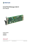
1
AdvancedTCA Shelf, 6-slot User’s Manual Product Number: 11596-160 11596-161 Doc-No: 63972-279_R1.0 October 19, 2010 Rev. Date updated Change D1.2 26.09.09 Draft Release D1.3 28.09.09 Minor corrections D1.4F 07.07.2010 Manual updated, Max. ambient temperature and supply voltage temporarily limited R1.0 19.10.2010 Initial release Impressum: Schroff GmbH D-75334 Straubenhardt, Germany The details in this manual have been carefully compiled and checked - supported by certified Quality Management System to EN ISO 9001/2000 The company cannot accept any liability for errors or misprints. The company reserves the right to amendments of technical specifications due to further development and improvement of products. Copyright2010 All rights and technical modifications reserved. Schroff 6-Slot ATCA Shelf 11596-160/-161 Table of Contents 1 2 Safety ................................................................................................................. 1 1.1 Safety Symbols used in this document................................................................ 1 1.2 General Safety Precautions................................................................................. 1 1.3 References and Architecture Specifications ........................................................ 2 1.4 Product Definition ................................................................................................ 2 1.5 Terms and Acronyms........................................................................................... 3 1.6 Hardware Platform............................................................................................... 4 1.7 Shelf Front and Rear View................................................................................... 5 1.8 ESD Wrist Strap Terminals.................................................................................. 5 ATCA Backplane............................................................................................... 6 2.1 Logical to Physical Slot Mapping ......................................................................... 6 2.2 Base Interface...................................................................................................... 7 2.3 Fabric Interface.................................................................................................... 7 2.4 Synchronization Clocks ....................................................................................... 8 2.5 Update Channel Interface.................................................................................... 8 2.6 Intelligent Platform Management Bus (IPMB)...................................................... 8 2.7 Shelf Manager Backplane Connectors ................................................................ 9 2.8 2.7.1 Fan Tray Connectors ............................................................................. 9 2.7.2 SAP Connector ...................................................................................... 9 Shelf SEEPROM.................................................................................................. 9 2.9 2.8.1 Shelf SEEPROM Location ..................................................................... 9 2.8.2 Shelf SEEPROMs I²C addresses......................................................... 10 Shelf Manager Cross Connect........................................................................... 10 2.10 Logic Ground ..................................................................................................... 11 3 4 Air Filter ........................................................................................................... 12 3.1 Introduction ........................................................................................................ 12 3.2 Air Filter Presence Switch.................................................................................. 12 Shelf Ground Connection .............................................................................. 13 4.1 5 Specification for the Shelf Ground connection cable ......................................... 13 Shelf Alarm Panel ........................................................................................... 14 5.1 Introduction ........................................................................................................ 14 5.2 SAP Front Panel ................................................................................................ 15 5.3 SAP Block Diagram ........................................................................................... 16 5.4 SAP SEEPROM................................................................................................. 16 5.5 SAP Temperature Sensor.................................................................................. 16 5.6 SAP PCA9555 ................................................................................................... 17 5.7 SAP I²C Addresses............................................................................................ 17 www.a-tca.com / www.schroff.biz I of IV R1.0, October 19, 2010 Schroff 6-Slot ATCA Shelf 11596-160/-161 5.8 User definable LEDs.......................................................................................... 17 5.9 RS-232 Serial Console Interfaces on SAP ........................................................ 18 5.10 SAP Console Cable for the Shelf Manger Serial Interface ................................ 18 5.11 Shelf Alarm Panel Backplane Connector........................................................... 19 5.12 SAP Telco Alarms.............................................................................................. 20 5.12.1 5.12.2 5.12.3 5.12.4 5.12.5 6 7 8 9 Telco Alarm Interface........................................................................... Telco Alarm LEDs ................................................................................ Alarm Silence Push Button .................................................................. Alarm Reset ......................................................................................... Telco Alarm Connector (DB15-male)................................................... 20 20 20 20 21 Fan Trays......................................................................................................... 22 6.1 Introduction ........................................................................................................ 22 6.2 Fan Tray Connectors and Indicators ................................................................. 23 6.3 Fan Tray Block Diagram .................................................................................... 24 6.4 Fan Tray Signals................................................................................................ 25 6.5 Fan Tray I/O Device........................................................................................... 25 6.6 Fan Tray Temperature Sensor .......................................................................... 26 6.7 Fan Tray Addresses .......................................................................................... 26 Power Entry Module (PEM) ............................................................................ 27 7.1 Introduction ........................................................................................................ 27 7.2 PEM Components.............................................................................................. 28 7.3 PEM Power Branches........................................................................................ 29 7.4 Slot Power Calculation....................................................................................... 30 7.5 PEM Block Diagram........................................................................................... 31 7.6 PEM I²C-bus addresses..................................................................................... 31 7.7 PEM I/O Device ................................................................................................. 32 7.8 PEM Connectors................................................................................................ 33 7.9 Specification for the power connection cables................................................... 33 Thermals.......................................................................................................... 34 8.1 System Airflow Path........................................................................................... 34 8.2 Cooling Capacity................................................................................................ 34 Shelf Managers ............................................................................................... 35 9.1 Introduction ........................................................................................................ 35 9.2 Front Panel Components................................................................................... 37 9.3 Bused IPMB Interface........................................................................................ 38 9.4 Radial IPMB Interface........................................................................................ 38 9.5 Ethernet Channels ............................................................................................. 39 9.6 Master-Only I²C Bus .......................................................................................... 40 9.7 Shelf Manager Cross Connect........................................................................... 41 www.a-tca.com / www.schroff.biz II of IV R1.0, October 19, 2010 Schroff 6-Slot ATCA Shelf 11596-160/-161 9.8 Shelf Manager RS-232 Console Serial Interface............................................... 42 9.9 Front Panel RESET push button ....................................................................... 42 9.10 Fan Control ........................................................................................................ 42 9.11 Cooling Management Strategy .......................................................................... 43 9.12 Hot Swap Interface ............................................................................................ 44 9.12.1 Hot Swap Switch.................................................................................. 9.12.2 Board Presence ................................................................................... 9.12.3 Hot Swap LED ..................................................................................... 9.13 Input Voltage and Fuse Monitoring.................................................................... 44 44 44 45 9.14 Hardware Address ............................................................................................. 45 9.15 Redundancy Control .......................................................................................... 46 9.15.1 Hardware Redundancy Interface ......................................................... 46 9.16 Command Line Interface (CLI) .......................................................................... 47 9.16.1 Basic CLI Commands .......................................................................... 47 9.17 Firmware Update ............................................................................................... 48 9.18 Shelf Manager Front Panel and Backplane connectors .................................... 49 10 Technical Data ................................................................................................ 53 10.1 Part Numbers..................................................................................................... 54 10.2 Dimensions ........................................................................................................ 55 www.a-tca.com / www.schroff.biz III of IV R1.0, October 19, 2010 Schroff 6-Slot ATCA Shelf 11596-160/-161 www.a-tca.com / www.schroff.biz IV of IV R1.0, October 19, 2010 Schroff 6-Slot ATCA Shelf Safety 11596-160/-161 1 Safety The intended audience of this User’s Manual is system integrators and hardware/software engineers. 1.1 Safety Symbols used in this document Hazardous voltage! This is the electrical hazard symbol. It indicates that there are dangerous voltages inside the Shelf. Caution! This is the user caution symbol. It indicates a condition where damage of the equipment or injury of the service personnel could occur. To reduce the risk of damage or injury, follow all steps or procedures as instructed. Danger of electrostatic discharge! The Shelf contains static sensitive devices. To prevent static damage you must wear an ESD wrist strap. 1.2 General Safety Precautions Warning! Voltages over 60 VDC can be present in this equipment. As defined in the PICMG 3.0 Specification, this equipment is intended to be accessed, to be installed and maintained by qualified and trained service personnel only. • Service personnel must know the necessary electrical safety, wiring and connection practices for installing this equipment. • Install this equipment only in compliance with local and national electrical codes. • For additional information about this equipment, see the PICMG 3.0 Specification (www.picmg.com). www.a-tca.com / www.schroff.biz 1 of 56 R1.0, October 19, 2010 Schroff 6-Slot ATCA Shelf Safety 11596-160/-161 1.3 References and Architecture Specifications • Pigeon Point Systems IPM Sentry Shelf-External Interface Reference (www.pigeonpoint.com) • Pigeon Point Systems Shelf Manager User Guide (www.pigeonpoint.com) • PICMG® 3.0 Revision 3.0 AdvancedTCA® Base Specification (www.picmg.com) 1.4 Product Definition The Schroff 11596-16x are 6 Slot AdvancedTCA Shelves for fault tolerant/high availability applications. • Product Number 11596-160: Replicated Mesh Backplane, bused IPMB • Product Number 11596-161: Replicated Mesh Backplane, radial IPMB The Schroff 11596-16x are designed to work with two redundant Schroff ShMM-ACB-V Shelf Managers and a Schroff Shelf Alarm Panel (SAP), at least one Shelf Manager is needed for a working System. Shelf Manager with bused IPMB: 21596-291 (Product Number) 21596-300 (Catalog Number with packaging) Shelf Manager with radial IPMB: 21596-292 (Product Number) 21596-301 (Catalog Number with packaging) The Shelf Managers are not included with the Shelf. www.a-tca.com / www.schroff.biz 2 of 56 R1.0, October 19, 2010 Schroff 6-Slot ATCA Shelf Safety 11596-160/-161 1.5 Terms and Acronyms Table 1: Terms and Acronyms Term Definition ATCA Advanced Telecom Computing Architecture Backplane Passive circuit board providing the connectors for the front boards. Power distribution, management and auxiliary signal connections are supported CDM Chassis Data Module Chassis Enclosure containing subrack, Backplane, boards, cooling devices, PEMs, same as Shelf CMM Chassis Management Module, same as Shelf Manager ECN Engineering Change Notice ESD Electrostatic Discharge ETSI European Telecommunications Standards Institute FRU Field Replaceable Unit IPMB Intelligent Platform Management Bus IPMC Intelligent Platform Management Controller IPMI Intelligent Platform Management Interface PCB Printed Circuit Board PEM Power Entry Module PSU Power Suppy Unit RTC Real Time Clock RTM Rear Transition Module SAP Shelf Alarm Panel Shelf See Chassis U Unit of vertical pitch. 1 U = 1.75 inches = 44.45 mm VRTN Voltage Return www.a-tca.com / www.schroff.biz 3 of 56 R1.0, October 19, 2010 Schroff 6-Slot ATCA Shelf Safety 11596-160/-161 1.6 Hardware Platform • Compliant to PICMG 3.0 Revision 3.0 ATCA Base Specification • Galvanized 5 U / 19“ chassis with front card cage for ATCA boards and rear card cage for ATCA RTM boards • 6 slot ATCA Backplane with replicated Mesh Fabric Interface, Dual Star Base Interface and bused or radial IPM interface, supporting four 8 U node board slots and two 8 U hub slots • Mounting brackets for 19“ racks and rear fixing points • ESD Wrist Strap Terminals at the front and the rear • Two dedicated Shelf Manager bays accepting Schroff Shelf Managers • Push-Pull Fan Tray arrangement provides optimized cooling for ATCA blades with fault tolerant capability • Two front pluggable, hot swappable Fan Trays • Air inlet filter with presence monitoring • Bay for front pluggable Shelf Alarm Panel (SAP): Provides Alarm Status LEDs, Telco Alarm interface and serial interfaces for the Shelf Managers • Two -48/-60 VDC hot swappable Power Entry Modules (PEMs) for redundancy • Cooling and electrical capacity up to 350 W/slot www.a-tca.com / www.schroff.biz 4 of 56 R1.0, October 19, 2010 Schroff 6-Slot ATCA Shelf Safety 11596-160/-161 1.7 Shelf Front and Rear View Figure 1: Shelf Front View 12710835 1 2 3 4 Shelf Alarm Panel (SAP) Shelf Manager 1 Fan Tray 1 ESD Wrist Strap Terminal 5 6 7 Slot for Shelf Manager 2 Air Filter Fan Tray 2 Figure 2: Shelf Rear View 12710839 1 2 3 PEM B ESD Wrist Strap Terminal Ground Terminal 4 5 6 Rear fixing points Shelf FRU EEPROMS PEM A 1.8 ESD Wrist Strap Terminals Danger of electrostatic discharge! The Shelf contains static sensitive devices. To prevent static damage you must wear an ESD wrist strap. One ESD Wrist Strap Terminal is located at the Shelf‘s upper front side, one ESD Wrist Strap Terminal is located at the left rear side of the Shelf. www.a-tca.com / www.schroff.biz 5 of 56 R1.0, October 19, 2010 Schroff 6-Slot ATCA Shelf ATCA Backplane 11596-160/-161 2 ATCA Backplane The 6-slot ATCA monolithic Backplane provides: • Four ATCA Node slots • Two ATCA Hub slots • Two dedicated Shelf Manager slots • Two PEM slots • One Shelf Alarm Panel (SAP) slot • Two Fan Tray slots 2.1 Logical to Physical Slot Mapping The physical and logical slots are sequentially numbered from the lower to the upper side of the Shelf. Table 2: 6-Slot ATCA Backplane physical to logical slot mapping Physical Slot Logical Slot HW-Address (Hex) IPMB-Address (Hex) Node 6 6 46 8C Node 5 5 45 8A Node 4 4 44 88 Node 3 3 43 86 Hub Slot 2 2 42 84 Hub Slot 1 1 41 82 www.a-tca.com / www.schroff.biz 6 of 56 Update Channel Routing R1.0, October 19, 2010 Schroff 6-Slot ATCA Shelf ATCA Backplane 11596-160/-161 2.2 Base Interface Logical slots 1 and 2 are the hub slots for the Dual Star Base Interface. Base Interface Channel 1 (ShMC) of logical slot 1 and 2 is cross connected to both dedicated Shelf Manager slots on the ATCA Backplane (as per PICMG 3.0 R2.0: ECN 3.0-2.0-001). See Chapter 2.9, "Shelf Manager Cross Connect" for details. Table 3: Base Interface Interconnections Connector Base Ch. Logical Slot 1 2 P23 1 ShMC ShMC P23 2 2-2 1-2 P23 3 3-1 3-2 P23 4 4-1 4-2 P23 5 5-1 5-2 P23 6 6-1 6-2 3 4 5 6 1-3 1-4 1-5 1-6 2-3 2-4 2-5 2-6 2.3 Fabric Interface The Fabric Interface in the ATCA Backplane is routed as triple replicated Full Mesh with 3 Channels (24 differential pairs total), interconnecting each ATCA slot. See PICMG® 3.0 AdvancedTCA® Base Specification for details. Table 4: 6 Slot Triple Replicated Mesh Fabric Interconnections Connector Fabric Channel Logical Slot 1 2 3 4 5 6 P20 15 6-11 6-12 6-13 6-14 6-15 5-15 P20 14 5-11 5-12 5-13 5-14 4-14 4-15 P20 13 4-11 4-12 4-13 3-13 3-14 3-15 P21 12 3-11 3-12 2-12 2-13 2-14 2-15 P21 11 2-11 1-11 1-12 1-13 1-14 1-15 P21 10 6-6 6-7 6-8 6-9 6-10 5-10 P21 9 5-6 5-7 5-8 5-9 4-9 4-10 P21 8 4-6 4-7 4-8 3-8 3-9 3-10 P22 7 3-6 3-7 2-7 2-8 2-9 2-10 P22 6 2-6 1-6 1-7 1-8 1-9 1-10 P22 5 6-1 6-2 6-3 6-4 6-5 5-5 P22 4 5-1 5-2 5-3 5-4 4-4 4-5 P22 3 4-1 4-2 4-3 3-3 3-4 3-5 P23 2 3-1 3-2 2-2 2-3 2-4 2-5 P23 1 2-1 1-1 1-2 1-3 1-4 1-5 www.a-tca.com / www.schroff.biz 7 of 56 M E S H 3 M E S H 2 M E S H 1 R1.0, October 19, 2010 Schroff 6-Slot ATCA Shelf ATCA Backplane 11596-160/-161 2.4 Synchronization Clocks 6 differential pairs of synchronization clocks are bused between all 8 ATCA slots and terminated at both ends with 80.6 Ohms between each differential pair. 2.5 Update Channel Interface The Update Channels are wired between two redundant ATCA Backplane slots as 10 differential pairs with 100 Ohms impedance. (See Table 2) The Update Channel is intended to pass information between two redundant ATCA Blades. 2.6 Intelligent Platform Management Bus (IPMB) The Shelf uses an Intelligent Platform Management Bus (IPMB) for management communications among all ATCA Boards and the Shelf Managers. The reliability of the IPMB is improved by the addition of a second IPMB, with the two IPMBs referenced as IPMB-A and IPMB-B. IPMB-A and IPMB-B are routed to the ATCA slots in: • a bused configuration (Product Number: 11596-160) • a radial configuration (Product Number: 11596-161) Figure 3: Bused and radial IPMB 12709848 www.a-tca.com / www.schroff.biz 8 of 56 R1.0, October 19, 2010 Schroff 6-Slot ATCA Shelf ATCA Backplane 11596-160/-161 2.7 Shelf Manager Backplane Connectors The front accessible Shelf Manager slots accept Schroff ACB-V Shelf Managers. The Backplane Connectors are wired to: • IPMB-A and IPMB-B (I2C) to the ATCA blades. • Base Interface cross connections to the Hub Slots • Presence connections to the SAP, Fan Trays and PEMs • RS-232 connections to SAP • Dedicated I2C to Shelf SEEPROMs The Shelf Manager Backplane Connectors also have interconnected signals that allow the Shelf Managers to run in a redundant configuration. 2.7.1 Fan Tray Connectors For pin assignment see Chapter 6.2, "Fan Tray Connectors and Indicators". 2.7.2 SAP Connector For pin assignment see Chapter 5.11, "Shelf Alarm Panel Backplane Connector". 2.8 Shelf SEEPROM The Shelf SEEPROM is a repository of the shelf specific information, capabilities of the system and other user configurable options. The SEEPROM contains as example: - a list of which slots are connected together how the update channels are routed how many slots are in the system what the maximum power is to each slot the serial number of the Shelf the backplane topology etc. The Shelf Managers use this information to provide functions such as electronic keying, controlling the power state of the system, etc. The Shelf Managers cache the information that is stored in the SEEPROMs so that the SEEPROM is only needed when the Shelf Managers are first inserted or when the Shelf is first turned on. The redundant SEEPROMs ensure that if one is corrupt or non-functional, the second can provide the necessary information. The Shelf Manager selects what set of information is correct and then synchronizes the two SEEPROMs from the internally cached copy of the SEEPROM information. 2.8.1 Shelf SEEPROM Location The SEEPROMs are located at the rear side of the backplane. www.a-tca.com / www.schroff.biz 9 of 56 R1.0, October 19, 2010 Schroff 6-Slot ATCA Shelf ATCA Backplane 11596-160/-161 2.8.2 Shelf SEEPROMs I²C addresses The SEEPROMs have the same address but are on different I²C-Channels! CDM I²C-Channel I²C-bus address SEEPROM1 Channel 1 0xa4 SEEPROM2 Channel 2 0xa4 2.9 Shelf Manager Cross Connect The ATCA Backplane provides cross connect traces between the Base Hubs and the Shelf Managers. Figure 4: Shelf Manager Cross Connect 12709808 Table 5: Connector (P23) pin assignments for Shelf Manager Cross Connect Row 5 Designation Shelf Manager Port with Shelf Manager Cross Connects www.a-tca.com / www.schroff.biz ab Tx1+ cd Tx1- Rx1+ ef Rx1- Shelf Manager Cross Connect 1 10 of 56 Tx2+ gh Tx2- Rx2+ Rx2- Shelf Manager Cross Connect 2 R1.0, October 19, 2010 Schroff 6-Slot ATCA Shelf ATCA Backplane 11596-160/-161 2.10 Logic Ground Figure 5: Logic Ground 12710837 The ATCA Backplane provides a mechanism to connect Logic Ground and Shelf Ground. To connect Logic Ground and Shelf Ground the mounting screws at the positions marked by arrows must have metallic washers (3) instead of isolating plastic washers (4). By default, Logic Ground and Shelf Ground is isolated, the chassis is shipped with the mounting screws with plastic washers at the marked positions. www.a-tca.com / www.schroff.biz 11 of 56 R1.0, October 19, 2010 Schroff 6-Slot ATCA Shelf Air Filter 11596-160/-161 3 Air Filter Figure 6: Air Filter 12709838 1 Air Filter Tray 2 Filter Element 3.1 Introduction The ATCA Shelf provides a front replaceable air filter. The filter element is an open cell polyurethane foam special coating to provide improved fire retardation and fungi resistance. The filter meets the requirements of the Telcordia Technologies Generic Requirements GR-78-CORE specification. 3.2 Air Filter Presence Switch The air filter presence is detected by an reed sensor on the backplane. The signal is routed to the Shelf Managers. www.a-tca.com / www.schroff.biz 12 of 56 R1.0, October 19, 2010 Schroff 6-Slot ATCA Shelf Shelf Ground Connection 11596-160/-161 4 Shelf Ground Connection Hazardous voltage! Before powering-up the Shelf, make sure that the Shelf Ground terminals are connected to Protective Earth (PE) of the building. The ATCA Shelf provides a Shelf ground terminal at the upper rear side.The Shelf ground terminal provides two threads (M6) with a 15.88 mm (5/8“) spacing between thread centers to connect a two hole lug Shelf ground terminal cable. Figure 7: Shelf Ground Terminal 12710838 1 Ground Terminal 4.1 Specification for the Shelf Ground connection cable Required wire size: AWG8 Required terminals: Use only two hole lug terminals. www.a-tca.com / www.schroff.biz 13 of 56 R1.0, October 19, 2010 Schroff 6-Slot ATCA Shelf Shelf Alarm Panel 11596-160/-161 5 Shelf Alarm Panel 5.1 Introduction Some I/O functions of the Schroff ACB-V Shelf Manager have been moved to a separate board called Shelf Alarm Panel (SAP). The Shelf Alarm Panel is a FRU and provides: • 3 Telco Alarm LEDs (MINOR, MAJOR, CRITICAL) • 3 User definable LEDs • The Telco Alarm connector (DB15-male) • The Alarm Silence Push Button • Serial console interfaces for Schroff Shelf Managers (RJ45 connectors) • Temperature sensor (LM75) • SEEPROM for FRU information The SAP is connected to the Schroff ACB-V Shelf Manager by a I²C connection, the signals from the serial connectors are routed directly to serial console interface on the Shelf Manager. Figure 8: SAP 12708941 www.a-tca.com / www.schroff.biz 14 of 56 R1.0, October 19, 2010 Schroff 6-Slot ATCA Shelf Shelf Alarm Panel 11596-160/-161 5.2 SAP Front Panel Figure 9: Front Panel SAP 12708813 1 Fixing screw 7 LED USER 2 2 Serial Interface for Shelf Manager 1 8 LED USER 3 3 LED Minor Alarm (amber) 9 Telco Alarm Connector 4 LED Major Alarm (red) 10 Alarm Silence button 5 LED Critical Alarm (red) 11 Serial Interface for Shelf Manager 2 6 LED USER 1 Figure 10: Connection between Shelf Manager and SAP 12706941 www.a-tca.com / www.schroff.biz 15 of 56 R1.0, October 19, 2010 Schroff 6-Slot ATCA Shelf Shelf Alarm Panel 11596-160/-161 5.3 SAP Block Diagram Figure 11: SAP Block Diagram SDA/SCL (I2C Bus CH0) User 1 LM75 Temp. Sensor User 2 LED Buffer 0x96 0xa6 Critical SAP Presence PCA9555 Major I2C-bus I/O port Minor 0x44 ALARM SILENCE I2C_PWR_A (ShMC1) TELCO Alarm Connector 3.3 V I2C_PWR_B (ShMC1) Critical Alarm I2C_PWR_A (ShMC2) Major Alarm I2C_PWR_B (ShMC2) Minor Alarm Backplane Connector ALARM LEDs User 3 SEEPROM INV_ACTIVE_ACB1 Power Alarm INV_ACTIVE_ACB2 Minor Clear Major Clear RJ45 ESD protection RJ45 ESD protection Serial Console of Shelf Manager 1 Serial Console of Shelf Manager 2 12706921 5.4 SAP SEEPROM The SAP SEEPROM is connected to the Master-Only I²C-bus and is a Microchip 24LC256 device. 5.5 SAP Temperature Sensor The LM75 temperature sensor measuring the board temperature is located on the SAP PCB. The temperature sensor is connected to the Master-Only I²C-bus. www.a-tca.com / www.schroff.biz 16 of 56 R1.0, October 19, 2010 Schroff 6-Slot ATCA Shelf Shelf Alarm Panel 11596-160/-161 5.6 SAP PCA9555 The PCA9555 device: • controls the status of the LEDs • reads the status of the Telco Alarm Cutoff push button (CLEAR) • controls the Telco Alarm relays Table 6: SAP PCA9555 Device Function D PCA9555 I/O pins Function State 0.0 Power Alarm to telco relays output 1 = relays powered 0.1 Minor Alarm to telco relays output 1 = relays powered 0.2 Major Alarm to telco relays output 1 = relays powered 0.3 Critical Alarm to telco relays output 1 = relays powered 0.4 N/C Pulled High 0.5 LED_MIN (Minor alarm LED) output 1 = On 0.6 LED_MAJ (Major alarm LED) output 1 = On 0.7 LED_CRIT (Critical alarm LED) output 1 = On 1.0 Alarm cutoff push button input 0 = push button pushed 1.1 Minor Clear input 0 = voltage applied to input pins 1.2 Major Clear input 0 = voltage applied to input pins 1.3 N/C Pulled High 1.4 N/C Pulled High 1.5 LED_USER3 output 1 = On 1.6 LED_USER2 output 1 = On 1.7 LED_USER1 output 1 = On 5.7 SAP I²C Addresses Table 7: SAP I²C Addresses LM75 SEEPROM PCA9555 0x96/0x4b 0xa6/0x53 0x44/0x22 5.8 User definable LEDs The LEDs USER (1, 2, 3) are user definable and connected to the I²C-bus I/O port of the PCA 9555 on the SAP. www.a-tca.com / www.schroff.biz 17 of 56 R1.0, October 19, 2010 Schroff 6-Slot ATCA Shelf Shelf Alarm Panel 11596-160/-161 5.9 RS-232 Serial Console Interfaces on SAP Figure 12: RS-232 Serial Console Interface on Shelf Alarm Display Pin 1 Pin 8 12705811 The SAP provides two RS-232 serial console connector (SERIAL 1 and 2) for Shelf Manager 1 and 2. The connectors are 8-pin RJ45 modular receptacles. A full set of RS-232 signals, including modem control, is provided. The serial interface is implemented on the Schroff Shelf Manager. The serial console default configuration is: • 115200 baud • no parity • 8 data bits • 1 stop bit Table 8: RS-232 Serial Console Interface Pin assignment RJ45 Pin RS-232 Signal ShMM-500 Signal Type Description 1 RTS RTS Out Request To Send 2 DTR DTR Out Data Terminal Ready 3 TxD TXD0 Out Transmit Data 4 GND GND --- Logic Ground 5 GND GND --- Logic Ground 6 RxD RXD0 In Receive Data 7 DSR DSR In Data Set Ready 8 CTS CTS In Clear To Send 5.10 SAP Console Cable for the Shelf Manger Serial Interface Figure 13: RJ45 to DB9 Serial Console Cable RJ45-male 1 8 RTS DTR TxD GND GND RxD DSR CTS 8 6 2 5 5 3 4 7 1 2 3 4 5 6 7 8 CTS DSR RxD GND GND TxD DTR RTS DB9-female 5 1 9 6 12706929 The connectors are shown with the cables pointing away. Serial Console Cable sold separately,Schroff Catalog-No: 23204-187 www.a-tca.com / www.schroff.biz 18 of 56 R1.0, October 19, 2010 Schroff 6-Slot ATCA Shelf Shelf Alarm Panel 11596-160/-161 5.11 Shelf Alarm Panel Backplane Connector Figure 14: Shelf Alarm Panel Backplane Connector 12706926 Table 9: Shelf Alarm Panel Backplane Connector Pin Assignment SAP ATCA Backplane Connector Pi n 1 A -48V_A Description -48 V Feed A B -48V_B Description C Description -48 V Feed B 2 VRTN_A Voltage return Feed A 3 VRTN_B Voltage return Feed B 4 5 I2C_PWR_A (1) 3.6 V from Shelf Manager 1 I2C_PWR_B (1) 3.6 V from Shelf Manager 1 6 GND Ground GND Ground I2C_PWR_A (2) 3.6 V from Shelf Manager 2 7 SDA_CH0 Data I²C-bus Channel 0 GND Ground I2C_PWR_B (2) 3.6 V from Shelf Manager 2 8 SCL_CH0 Clock I²C-bus Channel 0 INT 9 INV_ACTIVE_ACB2 Active signal from Shelf Manager 2 RXD0_ACB1 Receive Data Shelf Manager 1 RXD0_ACB2 Receive Data Shelf Manager 2 10 DSR_ACB1 Data Set Ready Shelf Manager 1 DTR_ACB1 Data Terminal Ready Shelf Manager 1 DSR_ACB2 Data Set Ready Shelf Manager 2 11 CD_ACB2 Carrier Detect Shelf Manager 2 DTR_ACB2 Data Terminal Ready Shelf Manager 2 CD_ACB1 Carrier Detect Shelf Manager 1 12 CTS_ACB1 Clear To Send Shelf Manager 1 CTS_ACB2 Clear To Send Shelf Manager 2 RTS_ACB1 Request To Send Shelf Manager 1 13 TXD0_ACB2 Transmit Data Shelf Manager 2 TXD0_ACB1 Transmit Data Shelf Manager 1 RTS_ACB2 Request To Send Shelf Manager 2 SHELF_GND Shelf Ground 14 15 SAP_PRES 16 INV_ACTIVE_ACB1 Active signal from Shelf Manager 1 GND SAP Presence signal to Shelf Manager www.a-tca.com / www.schroff.biz 19 of 56 R1.0, October 19, 2010 Schroff 6-Slot ATCA Shelf Shelf Alarm Panel 11596-160/-161 5.12 SAP Telco Alarms 5.12.1 Telco Alarm Interface The SAP provides a Telco Alarm interface on the DB15-male connector. Three relay outputs are used for remote alarm distribution, reflecting the state of the three Alarm LEDs. The relays are capable of carrying 72 VDC or 1 A with a max. rating of 30 VA. 5.12.2 Telco Alarm LEDs The Shelf Alarm Panel provides the Telco Alarm LEDs. These LEDs indicate presence of Critical, Major and Minor alarms as follows: Table 10: Telco Alarm LEDs State Description Off No alarm active On Alarm active Flashing Alarm active, but silenced 5.12.3 Alarm Silence Push Button The Alarm Silence push button on the Shelf Alarm Panel faceplate deactivates the alarm relays. During the time Alarm Silence is activated, the Alarm LEDs flash. By pressing the Alarm Silence push button a second time, the alarm relays are reactivated and the Alarm LEDs are solid. The Alarm Silence push button only activates the Alarm Silence state, but does not reset the alarms. If the silence interval (default 600 s) is exceeded without resolving the alarms, the alarms will be re-initiated. 5.12.4 Alarm Reset Hardware Reset: Two relay inputs at the DB15 connector are used to reset the Minor and Major alarm state. The reset inputs accept timed pulse inputs for clearing Minor and Major alarm states. Reset is accomplished by asserting a voltage differential from 3.3 VDC to 72 VDC for between 200 ms and 300 ms. The acceptance voltage range is from 0 to 48 VDC continuous (handles up to 60 VDC at a 50% duty cycle). The current drawn by a reset input does not exceed 12 mA. There is no hardware reset (reset input) for the Critical Alarm state. Software Reset: The RMCP and CLI functions can be used to set and reset the Telco Alarms (incl. Critical Alarm). See the Pigeon Point Shelf Manager External Interface Reference for more information. www.a-tca.com / www.schroff.biz 20 of 56 R1.0, October 19, 2010 Schroff 6-Slot ATCA Shelf Shelf Alarm Panel 11596-160/-161 5.12.5 Telco Alarm Connector (DB15-male) Figure 15: Telco Alarm Connector (DB15-male) 12705896 Table 11: Telco Alarm Connector Pin Assignment Pin Name Description 1 AMIR+ 2 AMIR- MinorReset+ MinorReset- 3 AMAR+ MajorReset+ 4 AMAR- MajorReset- 5 ACNO CriticalAlarm - NO 6 ACNC CriticalAlarm - NC 7 ACCOM CriticalAlarm - COM 8 AMINO MinorAlarm – NO 9 AMINC MinorAlarm – NC 10 AMINCOM MinorAlarm – COM 11 AMANO MajorAlarm – NO 12 AMANC MajorAlarm – NC 13 AMACOM MajorAlarm – COM 14 APRCO PwrAlarm – NO 15 APRCOM PwrAlarm - COM Shield Shelf-GND Shelf Ground www.a-tca.com / www.schroff.biz 21 of 56 R1.0, October 19, 2010 Schroff 6-Slot ATCA Shelf Fan Trays 11596-160/-161 6 Fan Trays 6.1 Introduction The 6 Slot ATCA Shelf contains two hot-swappable Fan Trays arranged in a side to side configuration for maximum air flow. The Fan Trays are locked into the Shelf by a mini compression latch with indicator. A hot-swap push button is used to provide hot-swap functionality. The Fan Trays are non-intelligent FRUs, monitored and controlled by the Shelf Managers through proprietary I²C connections. The system is designed to run indefinitely with any single fan failure. When one fan fails, all other fans are increased to full speed. The Fan Tray has sufficient cooling capacity to keep the Shelf cooled with a single fan failure. Figure 16: Fan Tray 12710840 1 Hot Swap Push Button 5 Mini Compression Latch 2 Hot Swap LED (blue) 6 Handle 3 Fan Tray Fault LED (red) 4 Fan Tray OK LED (green) 5 www.a-tca.com / www.schroff.biz 22 of 56 R1.0, October 19, 2010 Schroff 6-Slot ATCA Shelf Fan Trays 11596-160/-161 6.2 Fan Tray Connectors and Indicators The front panel includes a green and red status LED and a blue hot-swap LED. The Hot-Swap push button indicates to the Shelf Managers that the Fan Tray is about to be removed. Its use is optional, but it is provided so that service personnel can be trained to look for a blue LED to be illuminated on any active component before removing it from the system. Once the operator pushes the Hot-Swap button, the Shelf Manager is informed of the pending extraction. When the Shelf Manager feels it is “safe“ to remove the Fan Tray, the blue HotSwap LED illuminates solid. Table 12: LEDs on Fan Tray front panel Color Description Green OK LED Red Blue Hot Swap LED Status Condition Off No Power to the Fan Tray Solid green Normal Operation Solid red Attention Status (error condition) Off No Power to the Fan Tray or not OK to extract Fan Tray Short blink Preparing for extraction Solid blue Ready to remove Table 13: Fan Tray Signal Connector pin assignment Pin # Signal Pin # Signa Pin # Signal Pin # Signal Pin # Signal A1 VRTN B B1 VRTN B C1 VRTN B D1 VRTN B E1 VRTN B VRTN A B3 VRTN A C3 A2 A3 B2 A4 A5 B4 -48V B B5 -48V A B7 A6 A7 A10 A11 -48V B C5 -48V A C7 B9 B10 FAN 24 V RTN A12 B11 C9 C11 GND-D B13 GND-D C13 A14 GND-D B14 NSEAT C14 A15 GND-D B15 INT# C15 B16 D5 D7 FAN 24 V RTN D9 -48V B E5 -48V A E7 D11 -48V B) -48V A E8 FAN SPEED E9 PWM_C E10 FAN TK3 D12 GND-D VRTN A E6 D10 FAN TK2 E3 E4 D8 C12 A13 E2 VRTN A D6 -48V A C10 FAN TK1 B12 A16 -48V B C8 FAN 24 V D3 D4 C6 B8 FAN 24 V D2 VRTN A C4 B6 A8 A9 C2 E11 FAN TK4 E12 D13 HA 0 E13 GND (FT_PRES) D14 HA 1 E14 AIR FILT PR INV_ACTIVE1 D15 INV_ACTIVE2 E15 PEM PRES C16 D16 E16 A17 SCL_FT_LOCAL B17 I2C_PWR_A C17 SCL_CH3 D17 SCL_A14_R E17 SCL_B14_R A18 SDA_FT_LOCAL B18 I2C_PWR_B C18 SDA_CH3 D18 SDA_A14_R E18 SDA_B14_R A19 GND-D B19 GND-D C19 GND-D D19 GND-D E19 GND-D www.a-tca.com / www.schroff.biz 23 of 56 R1.0, October 19, 2010 Schroff 6-Slot ATCA Shelf Fan Trays 11596-160/-161 6.3 Fan Tray Block Diagram Figure 17: Fan Tray Block Diagram 12709840 www.a-tca.com / www.schroff.biz 24 of 56 R1.0, October 19, 2010 Schroff 6-Slot ATCA Shelf Fan Trays 11596-160/-161 6.4 Fan Tray Signals The Fan Tray provides signals for: • • • • Voltage monitoring Status of the Hot Swap Controller Fan Speed Temperature These signals are controlled by the Shelf Manager via the I²C bus and propietary signals. 6.5 Fan Tray I/O Device The Fan Tray I/O device (PCA9555): • controls the status of the LEDs • reads the status of the Hot Swap push button • reads the status of the DC/DC converter for the 24 VDC fan power supply • can enable the Hot Swap controller to switch off the fans Table 14: Fan Tray PCA9555 pin assignment I/O pins Function State 0.0 -48A bus voltage 0 = Voltage OK 0.1 -48A fan tray voltage 0 = Voltage OK 0.2 -48B bus voltage 0 = Voltage OK 0.3 -48B fan tray voltage 0 = Voltage OK 0.4 24 V converter OK 0 = Voltage OK 0.5 Fan Tray Off 0 = Fans switched off 0.6 N/C Pulled high 0.7 N/C Pulled high 1.0 N/C Pulled high 1.1 N/C Pulled high 1.2 N/C Pulled high 1.3 Green LED (OK) 1 = On 1.4 Hot swap push button switch 1 = not pushed, 0 = pushed 1.5 Red LED (Alarm) 1 = On 1.6 N/C Pulled high 1.7 Blue LED (Hot swap) 1 = On Configuration registers 6 and 7 in the PCA9555 control the direction of the I/O pins. Normally a 0xdf is written to register 6 and a 0x17 is written to register 7. This will make all pins to inputs except for 0.5, 1.7, 1.6, 1.5 and 1.3. Configuration registers 4 and 5 in the PCA9555 control the inversion of the I/O pins. Normally a 0x00 is written to register 4 and 5. This will make the polarity of all of the pins the same as the bits in the registers. www.a-tca.com / www.schroff.biz 25 of 56 R1.0, October 19, 2010 Schroff 6-Slot ATCA Shelf Fan Trays 11596-160/-161 6.6 Fan Tray Temperature Sensor The temperature sensors (LM75) in the Fan Trays measure the input and exhaust temperatures of the Shelf. 6.7 Fan Tray Addresses Geographic address pins (HA0, HA1) at the Fan Tray Backplane connector determine the hardware addresses of the devices. Table 15: Fan Tray Location SEEPROM LM75 PCA9555 #1 (Left) 0xa8/0x54 0x98/0x4c 0x48/0x24 #2 (Right) 0xac/0x56 0x9c/0x4e 0x4c/0x26 The addresses are shown in 8 bit/7 bit format. www.a-tca.com / www.schroff.biz 26 of 56 R1.0, October 19, 2010 Schroff 6-Slot ATCA Shelf Power Entry Module (PEM) 11596-160/-161 7 Power Entry Module (PEM) Hazardous voltage! Before working ensure that the power is removed from the power connection cables. When the system is powered on, do NOT touch the power terminals. The Shelf can be powered using a regular telecommunication power supply of -48/-60 VDC with a VDC return. The specified voltage range is from -40.5 VDC to -60 VDC.The Shelf supports redundant power supplies but the two supplies should be independently powered. 7.1 Introduction Two pluggable redundant Power Entry Modules (PEMs) are located at the rear top side of the Shelf. Each PEM provides power terminals for two 30 A power feeds. Each power feed consists of a –48 VDC cable and its corresponding return cable. The two feeds (Feed A1 and A2, Feed B1 and B2) and protected by a 30 A fused switches. Each of the two power feeds supplies power to a hub slots, two node slots a Fan Tray and a Shelf Manager. This topology is used for safety reasons to keep the max. current per feed less the 30 A. The segmentation is shown in Chapter 7.3, "PEM Power Branches". The power filtering consists of filtered power terminals and a discrete line-filter for each power input. The input voltage range for the Shelf is from -40.5 VDC to -60 VDC. To indicate the presence of the PEM, a PEM presence signal is grounded by the PEM. A Blue Hot Swap LED and a Hot Swap Push Button provide Hot Swap functionality. A red (power failure) and a green (OK) LED provide status indication. www.a-tca.com / www.schroff.biz 27 of 56 R1.0, October 19, 2010 Schroff 6-Slot ATCA Shelf Power Entry Module (PEM) 11596-160/-161 7.2 PEM Components Figure 18: PEM components 12709842 1 Hot Swap push button 5 Fused Switch Branch1 2 Hot Swap LED (blue) 6 Fused Switch Branch 2 3 PEM Alarm LED (red) 7 Power Terminal 4 PEM OK LED (green) www.a-tca.com / www.schroff.biz 28 of 56 R1.0, October 19, 2010 Schroff 6-Slot ATCA Shelf Power Entry Module (PEM) 11596-160/-161 7.3 PEM Power Branches The ATCA Backplane is divided into two Power branches. Each of the PEM’s two power feeds supplies power to a group of slots and a Fan Tray and a Shelf Manager. This topology is used to keep the max. current per branch less than 30 A. Figure 19: Power distribution of the two Power Branchs within the Shelf 12709843 Figure 20: Terminal block power connection 12710870 www.a-tca.com / www.schroff.biz 29 of 56 R1.0, October 19, 2010 Schroff 6-Slot ATCA Shelf Power Entry Module (PEM) 11596-160/-161 7.4 Slot Power Calculation Each branch supplies power to a Fan Tray, a Shelf Manager and a group of 3 slots. The Shelf Manager calculates the maximum branch power by the minimum expected operating voltage (default 40.5 V) and the maximum branch current (30 A) stored in the Shelf‘s FRU file. With the default settings the available branch power is calculated with 1215 W. With the power consumption of the Fan Tray and Shelf Manger is about 180 W, the remaing power for the 3 ATCA boards is 1035 W. Because the Shelf Manager reserves 10 W for the for the IPMC on each FRU, the actual remaining branch power is 1005W. If the Shelf is operated in an environment that allows a higher minimum voltage, the user can alter the settings for the minimum expected operating voltage in the FRU file to gain a higher branch power. The power capability per slot is set to 300 W in the Shelf‘s FRU file by default. If you want to use a board with more then 300 W, you must must modify the slot‘s power capability. For more information refer to the Pigeon Point Shelf Manager External Interface Reference Manual (www.pigeonpoint.com). If the joint power capability of all ATCA boards assigned to a branch is greater than the calculated branch power, the Shelf Manager will not power-on all boards. (The last plugged-in or the last in the power-up sequence.) Table 16: Branch Power Capability Input Max. Current/ Max. Power/ Power FT Slot Power Slot Power Max. Max. Power/ Voltage Branch Branch and ShMC (for 3 Slots) (average) Current/Slot single Slot 40.5 V 30 A 1215 W 180 W 1005 W 335 W 10.1 409.1 48 V 30 A 1440 W 180 W 1230 W 410 W 10.1 484.8 54 V 30 A 1620 W 180 W 1410 W 470 W 10.1 545.4 Note: You can modify the power capability of a FRU with the following CLI command: clia shelf PwrCapability [hw-addr] [FRU-ID] [Power] www.a-tca.com / www.schroff.biz 30 of 56 R1.0, October 19, 2010 Schroff 6-Slot ATCA Shelf Power Entry Module (PEM) 11596-160/-161 7.5 PEM Block Diagram Figure 21: PEM Block Diagram 12709841 7.6 PEM I²C-bus addresses Geographic address pins (HA0, HA1) on the PEM Backplane connector determine the I²C addresses of the devices. The I²C devices on the PEMs are connected to channel 4 of the Master-Only I²C-bus of the Shelf Managers. Table 17: PEM I²C-bus addresses PEM Location SEEPROM LM75 PCA9555 PEM A (Right, view from rear) 0xa8/54 0x98/4c 0x48/24 PEM B (Left, view from rear) 0xaa/55 0x9a/4d 0x4a/25 www.a-tca.com / www.schroff.biz 31 of 56 R1.0, October 19, 2010 Schroff 6-Slot ATCA Shelf Power Entry Module (PEM) 11596-160/-161 7.7 PEM I/O Device The PEM I/O device (PCA9555): • controls the status of the LEDs • reads the status of the Hot Swap push button • reads the status of the -48 VDC inputs Table 18: PEM PCA 9555 pin assignment PCA9555 I/O pin Function State 0.0 Power Input 2 at Backplane connector present -48 V present = 0 -48 V absent = 1 (3.3V) 0.1 Power Input 2 after the fuse present -48 V present = 0 -48 V absent = 1 (3.3V) 0.2 Power Input 1 at Backplane connector present -48 V present = 0 -48 V absent = 1 (3.3V) 0.3 Power Input 1 after the fuse present -48 V present = 0 -48 V absent = 1 (3.3V) 0.4 N/C Pulled High 0.5 N/C Pulled High 0.6 N/C Pulled High 0.7 N/C Pulled High 1.0 N/C Pulled High 1.1 N/C Pulled High 1.2 N/C Pulled High 1.3 Green LED 1=on 1.4 Hot Swap Push-button switch 1=not pushed, 0=pushed 1.5 Red LED 1=on 1.6 N/C Pulled High 1.7 Blue LED 1=on www.a-tca.com / www.schroff.biz 32 of 56 R1.0, October 19, 2010 Schroff 6-Slot ATCA Shelf Power Entry Module (PEM) 11596-160/-161 7.8 PEM Connectors Figure 22: PEM Backplane Connector 12709845 Table 19: PEM Backplane connector power contacts B1 B2 B3 B4 -48 V Feed 1 VRTN Feed 1 -48 V Feed 2 VRTN Feed 2 Table 20: PEM Backplane connector signal contacts Pin # 1 2 3 4 5 A SDA_CH4 I2C_PWR_A I2C_PWR_B B SCL_CH4 GND GND C HA0 HA1 D INT# PEM_PRES (GND) 6 7.9 Specification for the power connection cables Required wire size: Diameter AWG6 when using one-hole lugs for screw M4 Diameter AWG3 when using two-hole lugs for screw M4 max. length 2.5 to 3.0 m suitable for 60 A at 50° C ambient temperature. www.a-tca.com / www.schroff.biz 33 of 56 R1.0, October 19, 2010 Schroff 6-Slot ATCA Shelf Thermals 11596-160/-161 8 Thermals 8.1 System Airflow Path The Schroff 6 slot ATCA Shelf provides an airflow using two Fan Trays, one at each side of the Blade subrack. Each Fan Tray has 6 fans moving air from the right side to the left side of the Shelf in a push-pull arrangement. This arrangement provides excellent airflow as well as fault tolerance in the unlikely event of a fan failure. Figure 23: General airflow path for the 5 U/ 6 slot ATCA Shelf 12709846 8.2 Cooling Capacity The maximum system airflow (all fans at full speed) is 719 m³/h (422 CFM). The airflow is measured with with front and RTM test boards (Front board impedance = 37 Pa pressure drop at 50 m³/h (30 CFM), RTM board impedance = 24.9 Pa at 8.4 m³/h (5 CFM) The maximum average per slot cooling capacity is: • 390 W with t = 10 K • 600 W with t = 15 K www.a-tca.com / www.schroff.biz 34 of 56 R1.0, October 19, 2010 Schroff 6-Slot ATCA Shelf Shelf Managers 11596-160/-161 9 Shelf Managers This Chapter describes the Shelf Manager hardware. For explicit software documentation see: • Pigeon Point Shelf Manager User Guide • Pigeon Point Shelf Manager External Interface Reference • Schroff Shelf Manager User‘s Manual, Order-no. 63972-243 The documentation is available for registered users at www.schroff.biz Shelf Manager with bused IPMB: 21596-291 (Product Number) 21596-300 (Catalog Number with packaging) Shelf Manager with radial IPMB: 21596-292 (Product Number) 21596-301 (Catalog Number with packaging) The Shelf Managers are not included with the Shelf 9.1 Introduction The Schroff Shelf Manager ACB-V is a 78 mm x 280 mm board that fits into a dedicated Shelf Manager slot in a Schroff ATCA Shelf. The Shelf Manager has two main responsibilities: 1 Manage/track the FRU population and common infrastructure of a Shelf, especially the power, cooling and interconnect resources and their usage. 2 Enable the overall System Manager to join in that management/tracking through the System Manager Interface, which is typically implemented over Ethernet. The Shelf management based on the Pigeon Point Shelf management solution for AdvancedTCA products. The Shelf management software executes on the Pigeon Point Shelf Management Mezzanine 500 (ShMM-500), a compact SO-DIMM form-factor module, installed on the ACB-V carrier board. The ACB-V carrier board includes several on-board devices that enable different aspects of Shelf management based on the ShMM-500. These facilities include I²C-based hardware monitoring/control and GPIO expander devices. The ACB-V provides the Fan Controller for up to 9 Fans and individual Ethernet connections to both Base Hubs (ShMC cross connect). The Shelf Manager also provides an IPMB interface for the non-intelligent FRUs in a Schroff Shelf. The Shelf Manager communicate with the non-intelligent FRUs over I²C busses and expose the sensors for these FRUs at IPMB address 0x20. To maximize availability, the Schroff ATCA Shelves are designed to work with two redundant Schroff ShMM-ACB-V Shelf Managers. www.a-tca.com / www.schroff.biz 35 of 56 R1.0, October 19, 2010 Schroff 6-Slot ATCA Shelf Shelf Managers 11596-160/-161 Figure 24: Schroff Shelf Manager 12708845 1 Extraction handle 5 Backplane Connector (J2) 2 ShMM-500 6 Backplane Connector (J1) 3 RTC Backup Capacitor 7 Fixing screw 4 ACB-V Carrier Board www.a-tca.com / www.schroff.biz 36 of 56 R1.0, October 19, 2010 Schroff 6-Slot ATCA Shelf Shelf Managers 11596-160/-161 9.2 Front Panel Components Figure 25: Shelf Manager Front Panel Components 12708844 1 Fixing screw 6 RESET push button 2 ETH 0 Ethernet Service Connector (RJ45) 7 Shelf Manager Status LED (red) ETH 0 Link/Activity LED (yellow) 8 3 - Red = Out of Service (OOS) - On = Link - Solid Green = in Service, active Shelf Manager - Off = No Link - Blinking = in Service, Backup Shelf Manager - Blinking = Activity 4 Shelf Manager Status LED (green) ETH 1 Link/Activity LED (yellow) - On = Link 9 Hot Swap Switch - Activated by extraction handle - Off = No Link - Blinking = Activity 5 Hot Swap LED (blue) 10 Extraction handle - Solid Blue = ready to remove - Blinking = Hot Swap is requested - Off = No Hot Swap possible www.a-tca.com / www.schroff.biz 37 of 56 R1.0, October 19, 2010 Schroff 6-Slot ATCA Shelf Shelf Managers 11596-160/-161 9.3 Bused IPMB Interface Only Shelf Managers with Product Number: 21596-291 for Shelves 11596-160 The ShMM-500 provides two IPMBs. The IPMB-A and IPMB-B from the ShMM500 are routed directly to the Backplane connector. The ATCA Backplane buses the two IPMBs to the ATCA boards. The Active# signal of the ShMM-500 is used to switch on/off the pull-up resistors of the IPMBs. Figure 26: Block diagram bused IPMB 12708848 9.4 Radial IPMB Interface Only Shelf Managers with Product Number: 21596-292 for Shelves 11596-161 The IPMB-A and IPMB-B buses from the ShMM-500 are routed through IPMB buffers and switches to the Backplane connector J2. The ATCA Backplane connects the individual IPMBs to the ATCA boards. Figure 27: Block diagram radial IPMB 12708849 www.a-tca.com / www.schroff.biz 38 of 56 R1.0, October 19, 2010 Schroff 6-Slot ATCA Shelf Shelf Managers 11596-160/-161 9.5 Ethernet Channels The Shelf Manager provides two 10/100 Ethernet interfaces. The first Ethernet channel (ETH0) is routed either to the RJ45 connector on the front panel or to the ATCA Backplane connector J2 (default setting). The routing depends on the settings of the rocker switches S101 and S102. The ATCA Backplane routes ETH0 from the connector J2 to the ShMC port on the corresponding Base Interface Hub board. The second Ethernet channel (ETH1) is routed to the other Base Interface Hub board (ShMC Cross Connect). Both Ethernet ports support 10 Mb (10BASE-T) and 100 Mb (100BASE-TX) connections. The front panel ETH0 Ethernet connector is intended for service use only or for debugging purposes in laboratory environment. The computer which is connected to this interface must be located nearby the shelf manager with an Ethernet cable that is not longer than 10m. The front panel Ethernet connector MUST NOT be connected to a Telecommunication Network Circuit that leaves the building. The ETH0 interface of the shelf manager can manually be switched between the front panel RJ45 connector (“Front”-position of the rocker-switch) and the backplane connector going to the hub board base interface (“Back”-position of the rocker-switch). The ATCA specification requires a base channel interface between the shelf manager and the Hub board. The ETH0 rocker-switch MUST be in “Back”position in normal operation of the shelf manager in an ATCA-shelf. Figure 28: Switches S101 and S102 shown in default position 12708853 www.a-tca.com / www.schroff.biz 39 of 56 R1.0, October 19, 2010 Schroff 6-Slot ATCA Shelf Shelf Managers 11596-160/-161 9.6 Master-Only I²C Bus The master-only I²C bus is used internally on the ShMM-500 for the RTC and SEEPROM devices. The Shelf Manager also has a number of onboard I²C devices connected to the master-only I²C bus. These devices read the slot's hardware address, communicate with the System Management controllers ADM1024/1026 and monitor the presence signals from the PEMs and Fan Trays. The master-only I²C bus is fed to a 4-channel switch and then routed to: • the Shelf FRU SEEPROMs (Channel 1 and 2) • the Fan Trays (Channel 3) • the PEMs (Channel 4) The master only I²C-bus is also buffered by a LTC4300 device and then routed to the SAP.The ’Active’ signal of the ShMM-500 is used to enable the LTC4300 buffers, so that only the active Shelf Manager has access to the Shelf I²C-bus devices. Figure 29: Master-Only I²C-bus 12709847 www.a-tca.com / www.schroff.biz 40 of 56 R1.0, October 19, 2010 Schroff 6-Slot ATCA Shelf Shelf Managers 11596-160/-161 9.7 Shelf Manager Cross Connect The ATCA Backplane provides cross connect traces between the Base Hubs and the Shelf Managers according to PICMG 3.0 Base specification. Figure 30: Shelf Manager Cross Connect ATCA Base 12709808 Table 21: Connector (P23) pin assignment for Shelf Manager Cross Connect Row Designation 5 Shelf Manager Port with Shelf Manager Cross Connects www.a-tca.com / www.schroff.biz ab Tx1+ cd Tx1- Rx1+ ef Rx1- Shelf Manager Cross Connect 1 41 of 56 Tx2+ gh Tx2- Rx2+ Rx2- Shelf Manager Cross Connect 2 R1.0, October 19, 2010 Schroff 6-Slot ATCA Shelf Shelf Managers 11596-160/-161 9.8 Shelf Manager RS-232 Console Serial Interface A serial interface is implemented on the ShMM-500.The Shelf Manager provides an RS-232 console interface that provides a full set of RS-232 signals, including modem control. These signals are routed through the Shelf Manager backplane connector to a RJ45 connector on the front panel of the Shelf Alarm Panel. The serial console default configuration is: • 115200 baud • no parity • 8 data bits • 1 stop bit 9.9 Front Panel RESET push button The Shelf Manager provides a RESET push button on the front panel. It is connected to the ShMM-500's /MR signal. Pushing the RESET button will reset the Shelf Manager 9.10 Fan Control The Shelf Manager provides fan control functionality through the ADM1024/ 1026 system management controllers. The fan speed is controlled by a 75 Hz PWM signal generated on the ADM1026. The PWM output from the ADM1026 is buffered and enabled by the ShMM500’s ACTIVE# signal so that only the active Shelf Manager controls the fan speed. The PWM signal is opto-isolated and routed to the backplane connector. For voltage-regulated Fans the Shelf Manager provides a converter that converts the PWM signal into a DC-voltage of 0 V to 10 V, referenced to the ground level of the Fan Tray electronics (FAN_24V_RTN), which is also available on the backplane connector. The tachometer signals from the Fan Trays are routed through the backplane connector opto-isolated to the digital inputs of the ADM1026. Three digital inputs to the ADM1026 (FANP0..2/GPIO9..GPIO11) are used to detect the presence of the Fan Trays. The Fan Tray grounds the signal to indicate that it is installed. www.a-tca.com / www.schroff.biz 42 of 56 R1.0, October 19, 2010 Schroff 6-Slot ATCA Shelf Shelf Managers 11596-160/-161 9.11 Cooling Management Strategy The cooling management strategy described below is part of the Pigeon Point Shelf Manager User Guide © by Pigeon Point Systems®. The default cooling management has the following features: • zoned cooling is supported; the Shelf Fan Geography Record from the Shelf FRU Information is used to define cooling zones. • in the normal cooling state (that is, when no thermal thresholds on any sensors are crossed), the Shelf Manager attempts to minimize the fan level, but at the same time prevent thermal alerts. It does that by adaptively choosing the lowest possible fan level that allows the shelf to avoid thermal alerts, for each fan, taking cooling zones into account. • In the minor alert cooling state (non-critical thermal thresholds are crossed for one or more sensors) the Shelf Manager periodically increases the fan level for the fans that serve the cooling zone(s) where those thresholds have been crossed, until the fan level reaches its maximum or the thermal condition goes away. • In the major alert cooling state (critical thermal thresholds are crossed for one or more sensors) the Shelf Manager sets the fan level to the maximum for the fans that serve the cooling zone(s) where those thresholds have been crossed. In addition, if the thermal condition is caused by a specific FRU, and the FRU supports power levels lower than the current one, the Shelf Manager reduces power consumption of the FRU by assigning it the next lower power level. • In the critical alert cooling state (non-recoverable thermal thresholds are crossed for one or more sensors) the Shelf Manager sets the fan level to maximum for the fans that serve the cooling zone(s) where those thresholds have been crossed. In addition, if the thermal condition is caused by a specific FRU, the FRU is powered down. If the thermal alert is caused by a shelf-wide temperature sensor, all FRUs are powered down, as prescribed by the PICMG 3.0 specification. • In addition, a fan management strategy is implemented that sets the fan level to the maximum for all fans in the cooling zone in the following cases: - If one or more fans are missing in the shelf, based on the fan population specified in the Address Table in the Shelf FRU Information, all fan trays are set to maximum. - If one or more of the fan tachometer sensors have a major or critical threshold crossed (a fan is stopped or rotates too slowly), all fan trays are set to maximum speed. www.a-tca.com / www.schroff.biz 43 of 56 R1.0, October 19, 2010 Schroff 6-Slot ATCA Shelf Shelf Managers 11596-160/-161 9.12 Hot Swap Interface The Shelf Manager provides a Hot Swap interface allowing the Shelf Manager to be replaced without powering down the Shelf. The Hot Swap interface is implemented using the on-ShMM-500 CPLD device. The interface is composed of three components: • Hot Swap switch at injector/ejector handle • Presence signal indicating that the Shelf Manager is fully seated in its backplane connector • Hot Swap LED 9.12.1 Hot Swap Switch The injector/ejector micro-switch provides an input (HS_LATCH) to the ShMM-500 CPLD, which is responsible for taking appropriate hardware actions as well as signaling the condition to the software. Micro-Switch HS_LATCH Signal HSL Bit in the CPLD Condition Open High 0 Handle opened Closed Low 1 Handle closed 9.12.2 Board Presence Each Shelf Manager grounds the PRES_1# input signal of the other Shelf Manager when installed into the ATCA Backplane. This signal is responsible for taking appropriate hardware action as well as signaling the condition to the software. 9.12.3 Hot Swap LED The Shelf Manager provides a a blue Hot Swap LED. The LED indicates when it is safe to "remove" the Shelf Manager from a powered Shelf. Table 22: Hot Swap LED LED State Condition Off The Shelf Manager is not ready to be removed/disconnected from the Shelf Solid Blue The Shelf Manager is ready to be removed/disconnected from the Shelf Long-blink The Shelf Manager is activating itself Short-blink Deactivation has been requested www.a-tca.com / www.schroff.biz 44 of 56 R1.0, October 19, 2010 Schroff 6-Slot ATCA Shelf Shelf Managers 11596-160/-161 9.13 Input Voltage and Fuse Monitoring To detect a missing supply voltage as well as a blown fuse the Shelf Manager provides voltage monitoring and control functions. The -48 VDC input voltage before and behind the fuses are connected to the ADM1026 chip through optical-isolation devices. Figure 31: Input Voltage and Fuse Monitoring To ADM1026 Fuse monitoring -48 V_A bus voltage -48 V_B ACB voltage -48 V_A ACB voltage VRTN_A - 48 V_A + 3.6V DC/DC converter VRTN_B - - 48 V_B Backplane Connector (J1) -48 V_B bus voltage 12705829 Signal description -48 V_A bus voltage Indicates the presence of the –48 V_A / VRTN_A at the backplane connector (J1). This signal is connected to pin 46 of the ADM1026 -48 V_A ACB voltage Indicates the presence of the –48 V_A / VRTN_A behind the Shelf Manager’s mains fuse. This signal is connected to pin 44 of the ADM1026 -48 V_B bus voltage Indicates the presence of the –48 V_B / VRTN_B at the backplane connector (J1). This signal is connected to pin 45 of the ADM1026 -48 V_B ACB voltage Indicates the presence of the –48 V_B / VRTN_B behind the Shelf Manager’s mains fuse. This signal is connected to pin 43 of the ADM1026 9.14 Hardware Address The Shelf Manager reads the hardware address and parity bit from the backplane connector of the Dedicated Shelf Manager slot. Geographic address pins (HA[0], HA7) at the Backplane connector determine bit 0 and bit 7, bit 1...6 are hardware-coded on the Shelf Manager PCB. HW-Addr. IPMB-Addr. Primary Shelf Manager (upper) 0x08 0x10 Secondary Shelf Manager (lower) 0x09 0x12 www.a-tca.com / www.schroff.biz 45 of 56 R1.0, October 19, 2010 Schroff 6-Slot ATCA Shelf Shelf Managers 11596-160/-161 9.15 Redundancy Control The Shelf Manager supports redundant operation with automatic switchover using redundant Shelf Managers. In a configuration where two Shelf Manager are present, one acts as the active Shelf Manager and the other as a standby. The Shelf Managers monitor each other and either can trigger a switchover if necessary. 9.15.1 Hardware Redundancy Interface The hardware redundancy interfaces of the Shelf Managers are as follows: • Cross connected Shelf Manager present input (PRES_1#) and output (PRES_GND#) • Cross connected Shelf Manager health input (HLY_Input#) and output (HLY_Output#) • Cross connected negotiation input (SWR_Input#) and output (SWR_Output#) • Active output from the ShMM-500 (ACTIVE#) that is used by the Shelf Manager to enable interfaces that must be exclusively driven by the active Shelf Manager, specifically PWM and fan tachometer buffers • Two status LEDs using the SWS_LED_G# (Green) and SWS_LED_R# (Red) signals • The PRES_1# signal is grounded on the redundant Shelf Manager. This indicates both Shelf Managers the presence of the other. The figure below shows the hardware redundancy interface of the Shelf Manager. Figure 32: Shelf Manager redundancy control Shelf Manager 1 Shelf Manager 2 Backplane J1/J2 ShMM-500 J1/J2 PRES_1# PRES_1# PRES_GND# PRES_GND# HLY_Input# HLY_Input# HLY_Output# HLY_Output# SWR_Input# SWR_Input# SWR_Output# SWR_Output# SWS_LED_R# SWS_LED_R# SWR_LED_G# SWR_LED_G# Green Red Red ShMM-500 Green ACTIVE# ACTIVE# PWM Buffer PWM Buffer 12705830 www.a-tca.com / www.schroff.biz 46 of 56 R1.0, October 19, 2010 Schroff 6-Slot ATCA Shelf Shelf Managers 11596-160/-161 9.16 Command Line Interface (CLI) The Command Line Interface (CLI) connects to and communicates with the IPM-devices of the Shelf, the boards, and the Shelf Manager. The CLI is an IPMI-based library of commands, service personnel or system administrators can access the CLI through Telnet, SSH, or the Shelf Managers serial port on the SAP. With the CLI, users can access information about the current system status including sensor values, threshold settings etc. Users can also access and modify Shelf- and Shelf Manager configurations, perform actions on a FRU a.e. set fan speeds etc. The default user account is “root“ and there is no password. The default IP address of the primary Shelf Manager is 192.168.0.2 To access all sensor datas you have to connect to the active Shelf Manager! 9.16.1 Basic CLI Commands Service personnel can read system information, FRU information and sensor datas with the following basic commands. For a full list of all CLI commands refer to the Pigeon Point Shelf Manager External Interface Reference Manual. • Change IP address of the primary Shelf Manager: clia setlanconfig channel ip value Value represents the IP address in dotted decimal notation. clia setlanconfig 1 ip 192.168.0.2 • Display the Shelf Managers firmware version: clia version Info: To get a complete list of all information just type in “version“. • List all IPM Controllers in a Shelf: clia ipmc • List all boards in the Shelf: clia board • List all sensors on a board: clia sensor IPMI-address • List only sensors which are outside of established thresholds: clia sensor -t • Get data (value) from a sensor on a board: clia sensordata IPMI-address sensor-number www.a-tca.com / www.schroff.biz 47 of 56 R1.0, October 19, 2010 Schroff 6-Slot ATCA Shelf Shelf Managers 11596-160/-161 • Display the FRU information in a board: clia fruinfo IPMI-address FRU-id • Change the speed for a Fan Tray: clia setfanlevel IPMI-address Fru-id speed Info: The value for the speed is from 0 to 15. • Display the contents of the System Event Log (SEL): clia sel • Clear the System Event Log (SEL): clia sel clear 9.17 Firmware Update The Shelf Management software is stored in the FLASH memory on the ShMM-500. The software is: U-boot sentry.kernel sentry.rfs The U-boot program is usually permanent and allows the user to configure the software and network environment of the ShMM-500 and install new software from a network server. Sentry.kernel is the ShMM-500's Linux kernel and sentry.rfs is the ShMM-500's root file system. A detailed instruction on how to reprogram the Shelf Manager is distributed with each new Firmware release. www.a-tca.com / www.schroff.biz 48 of 56 R1.0, October 19, 2010 Schroff 6-Slot ATCA Shelf Shelf Managers 11596-160/-161 9.18 Shelf Manager Front Panel and Backplane connectors Table 23: Front Panel 10/100 Ethernet Service Connector Pin # Ethernet Signal 1 TX+ 2 TX- 3 RX+ 4, 5 n.c. 6 RX- 7, 8 n.c. Figure 33: Backplane Connectors 12706898 Table 24: Pin Staging (PS) Pin# length A 8.25 mm B 9.75 mm C 11.25 mm The Pin Staging (PS) is the length of the Pins of the connector at the Backplane not at the Shelf manager. Table 25: Backplane Signal Connector (J1) pin assignment a 1 -48 V_A PS B 2 3 SHELF_GND b VRTN_A PS B B 4 - SHELF_GND 5 FAN_TACH0 6 FAN_TACH5 7 FAN_SPEED FAN_TACH1 A FAN_TACH6 A NC 9 PEM_PRES_A 10 TX+ 11 AIR_FILT_PR SHELF_GND FAN_TACH7 A FAN_24V TX- A PEM_PRES_B B SHELF_GND VRTN_B PS B B SHELF_GND B - FAN_TACH3 FAN_TACH4 A A FAN_TACH8 A PWM_C A A FAN_24V_RTN A PWM_E A - SWR_Input# A A HS_EN A RX+ 49 of 56 e A - A -48 V_B PS - A SAP_PRES d - B FAN_TACH2 A www.a-tca.com / www.schroff.biz NC A A B A 8 - PS B A c - HLY_Input# A SWR_Output# A A HLY_Output# A HA7 A A RX- A PRES_1# A R1.0, October 19, 2010 Schroff 6-Slot ATCA Shelf Shelf Managers 11596-160/-161 Table 26: Backplane Signal Connector pin assignment (Bused IPMB) a PS b PS c PS d PS e PS f GND 1 FAN_PRES0 A TXD0 A TXD1 A FAN_PRES2 A INT# A 2 FAN_PRES1 A DTR A Pres_GND A CI A DSR A 3 CD A RTS A RXD1 A HA[0] A CTS A 4 RXD0 A SDA_CH1 A INV_ACTIVE A SDA_CH0 A GND A 5 SCL_CH1 A SCL_CH0 A RI A GND A SDA_CH3 A 6 S1_TX+ A S1_TX- A GND B S2_TX+ A S2_TX- A 7 S1_RX+ A S1_RX- A GND B S2_RX+ A S2_RX- A 8 SDA_CH4 A SCL_CH4 A SCL_CH3 A SCL_CH2 A I2C_PWR_B A 9 A A A A SDA_CH2 A 10 A A A A I2C_PWR_A A 11 A A A A A 12 A A A A A 13 A A A A A 14 A A A A A 15 A 16 A IPMB_SDA_B A IPMB_SCL_B A A A A A A A 17 CROSS_SDA_B A A A A A 18 CROSS_SCL_B A A A IPMB_SDA_A A A 19 A A A I A A 20 A A A CROSS_SDA_A A A CROSS_SCL_A IPMB_SCL_A 21 A A A A A 22 A A A A A PS C C C GND C C GND C C GND C C GND GND GND C C GND C C GND C C GND C C GND C Table 27: Backplane Signal Connector pin assignment (Radial IPMB) a 1 FAN_PRES0 PS A b TXD0 PS A c PS A TXD1 d FAN_PRES2 PS A e INT# PS f PS A GND C 2 FAN_PRES1 A DTR A Pres_GND A CI A DSR A 3 CD A RTS A RXD1 A HA[0] A CTS A 4 RXD0 A SDA_CH1 A INV_ACTIVE A SDA_CH0 A GND A 5 SCL_CH1 A SCL_CH0 A RI A GND A SDA_CH3 A 6 S1_TX+ A S1_TX- A GND B S2_TX+ A S2_TX- A 7 S1_RX+ A S1_RX- A GND B S2_RX+ A S2_RX- A 8 SDA_CH4 A SCL_CH4 A SCL_CH3 A SCL_CH2 A I2C_PWR_B A 9 IPMB_SCL_B15 A IPMB_SDA_B15 A IPMB_SCL_A15 A IPMB_SDA_A15 A SDA_CH2 A 10 IPMB_SDA_B16 A IPMB_SCL_B16 A IPMB_SDA_A16 A IPMB_SCL_A16 A I2C_PWR_A A 11 IPMB_SDA_A3 A IPMB_SDA_B3 A IPMB_SCL_B3 A IPMB_SDA_B8 A IPMB_SCL_B8 A 12 IPMB_SCL_A3 A IPMB_SDA_A5 A IPMB_SCL_A5 A IPMB_SDA_A8 A IPMB_SCL_A8 A 13 IPMB_SDA_A1 A IPMB_SDA_B7 A IPMB_SCL_A1 A IPMB_SDA_A10 A IPMB_SCL_A10 A 14 IPMB_SCL_B7 A IPMB_SDA_A7 A IPMB_SCL_A7 A IPMB_SDA_A6 A IPMB_SCL_A6 A 15 IPMB_SDA_A9 A IPMB_SDA_B14 A IPMB_SCL_B14 A IPMB_SDA_B10 A IPMB_SCL_B10 A 16 IPMB_SCL_A9 A IPMB_SDA_A4 A IPMB_SCL_A4 A IPMB_SDA_B6 A IPMB_SCL_B6 A 17 CROSS_SDA_B A IPMB_SDA_B11 A IPMB_SCL_B11 A IPMB_SDA_B4 A IPMB_SCL_B4 A 18 CROSS_SCL_B A IPMB_SDA_A11 A IPMB_SCL_A11 A IPMB_SDA_A14 A IPMB_SCL_A14 A 19 IPMB_SDA_A13 A IPMB_SCL_A13 A IPMB_SCL_B12 A IPMB_SDA_B12 A IPMB_SDA_B9 A 20 IPMB_SDA_B1 A IPMB_SCL_B1 A CROSS_SCL_A A CROSS_SDA_A A IPMB_SCL_B9 A 21 IPMB_SDA_B13 A IPMB_SDA_B5 A IPMB_SCL_B5 A IPMB_SDA_B2 A IPMB_SCL_B2 A 22 IPMB_SCL_B13 A IPMB_SDA_A12 A IPMB_SCL_A12 A IPMB_SDA_A2 A IPMB_SCL_A2 A www.a-tca.com / www.schroff.biz 50 of 56 C GND C C GND C C GND C C GND C GND GND C GND C C GND C C GND C C GND R1.0, October 19, 2010 C C Schroff 6-Slot ATCA Shelf Shelf Managers 11596-160/-161 Table 28: Backplane connector (J1) and (J2) pin description -48V_A -48 VDC supply A -48V_B -48 VDC supply B AIR_FILT_PR Air filter presence (grounded by air filter presence switch to detect a missing air filter) CD Serial Interface 1 Carrier Detect CI Chassis Intrusion signal of ADM1026 CROSS_SCL_A Serial Clock of IPMB-A, cross-connected on Backplane to serial clock of IPMBB of other Shelf Manager CROSS_SCL_B Serial Clock of IPMB-B, cross-connected on Backplane to serial clock of IPMBA of other Shelf Manager CROSS_SDA_A Serial Data of IPMB-A, cross-connected on Backplane to serial data of IPMB-B of other Shelf Manager CROSS_SDA_B Serial Data of IPMB-B, cross-connected on Backplane to serial data of IPMB-A of other Shelf Manager CTS Serial Interface 1 Clear To Send DSR Serial Interface 1 Data Set Ready DTR Serial Interface 1 Data Terminal Ready FAN_24V Auxiliary 24 VDC (max. 100 mA) generated on Fan Trays (Voltage supply for opto-couplers on Shelf Manager) FAN_24V_RTN Return path (Ground reference) for the auxiliary 24 VDC, generated on Fan Trays, used also as reference ground for the fan control voltage FAN_PRES[0...2] Fan Tray present (grounded on Fan Tray when present) FAN_SPEED DC for Fan Speed Control (0 V to 10 V, 10 mA) FAN_TACH[0...8] Tachometer signals from Fan Trays GND logic ground HA[0] Hardware address of Shelf Manager - grounded: Shelf Manager IPMI address is 0x10 - open: Shelf Manager IPMI address is 0x12 HA7 Hardware address of Shelf Manager - grounded: Shelf Manager IPMI address is 0x10 - open: Shelf Manager IPMI address is 0x12 HLY_Input# Health input Shelf Manager (proprietary signal cross-connected on Backplane to HLY_Output of other Shelf Manager) HLY_Output# Health output Shelf Manager (proprietary signal cross-connected on Backplane to HLY_Input of other Shelf Manager) HS_EN Tells the Shelf Manager that it is plugged in (Grounded on Backplane) I2C_PWR_A I2C_PWR_B 3.6 V (max. 500 mA) generated on Shelf Manager, redundant path A for Shelf I2C-devices on Fan Trays, PEMs and SAP 3.6 V (max. 500 mA) generated on Shelf Manager, redundant path B for Shelf I2C-devices on Fan Trays, PEMs and SAP INT# External Interrupt request (Master Only I2C-bus) INV_ACTIVE This ShMM is in active mode (inverted signal of ShMM) IPMB_SCL_A_[1...16] Serial Clock, IPMB-A IPMB_SCL_B_[1...16] Serial Clock, IPMB-B IPMB_SDA_A_[1...16] Serial Data, IPMB-A IPMB_SDA_B_[1...16] Serial Data, IPMB-B www.a-tca.com / www.schroff.biz 51 of 56 R1.0, October 19, 2010 Schroff 6-Slot ATCA Shelf Shelf Managers 11596-160/-161 NC not connected PEM_PRES_[A, B] PEM [A, B] presence signal (grounded on PEM when present) PRES_1# Shelf Manager board presence signal (proprietary signal cross-connected on Backplane to PRES_GND of other Shelf Manager) PRES_GND# Shelf Manager presence ground (proprietary signal cross-connected on Backplane to PRES_1# of other Shelf Manager) PWM_C Opto isolated PWM signal for fan speed control, collector UCE0 = max. 70 V, Imax = 2 mA PWM_E Opto isolated PWM signal for fan speed control, emitter, connected to FAN_24V_RTN on Backplane RI Serial Interface 1 Ring Indication RTS Serial Interface 1 Request To Send RX(+-) Ethernet interface (ETH1) to Hub-Slot (ShMC cross connect) RXD0 Serial Interface 1 Receive Data RXD1 Serial Interface 2 Receive Data (not used in Schroff Shelves) S1_RX(+-) Ethernet interface (ETH0) S1_TX(+-) Ethernet interface (ETH0) S2_RX(+-) USB interface, cross-connected on Backplane to S2_TX(+-) of other Shelf Manager S2_TX(+-) USB interface, cross-connected on Backplane to S2_RX(+-) of other Shelf Manager SAP_PRES Presence signal of SAP (Grounded on SAP when present) SCL_CH0 Master Only-I2C-bus Channel 0 to SAP SCL_CH1 Master-Only I2C-bus Channel 1 SCL_CH2 Master-Only I2C-bus Channel 2 SCL_CH3 Master-Only I2C-bus Channel 3 SCL_CH4 Master-Only I2C-bus Channel 4 SDA_CH0 Master Only-I2C-bus Channel 0 to SAP SDA_CH1 Master-Only I2C-bus Channel 1 SDA_CH2 Master-Only I2C-bus Channel 2 SDA_CH3 Master-Only I2C-bus Channel 3 SDA_CH4 Master-Only I2C-bus Channel 4 SHELF_GND Shelf Ground SWR_Input# Switchover signal from the other Shelf Manager (proprietary signal cross-connected on Backplane to SWR_Output of other Shelf Manager) SWR_Output# Switchover signal to the other Shelf Manager (proprietary signal cross-connected on Backplane to SWR_Input of other Shelf Manager) TX(+-) Ethernet interface (ETH1) TXD0 Serial interface 1 Transmit Data TXD1 Serial interface 2 Transmit Data (not used in Schroff Shelves) VRTN_A Voltage return supply A VRTN_B Voltage return supply B www.a-tca.com / www.schroff.biz 52 of 56 R1.0, October 19, 2010 Schroff 6-Slot ATCA Shelf Technical Data 11596-160/-161 10 Technical Data Table 29: Technical Data Physical Dimensions Height 5U Width 482.6 mm Depth (with handles) 464 mm Weight Shipping weight completely assembled with packaging 20 Kg Shelf weight completely assembled 15 Kg Power Input voltage -40.5 VDC …. -72 VDC Input Power 60 A per power feed (Feed A and Feed B) Overcurrent Protection 30 A Fused Switches on PEM Cooling Capacity Front Boards >300 W / Board RTM 30 W / Board Environmental Ambient temperature (long term) +5°C…+40°C (41°F to 104°F) Ambient temperature (short term) -5°C…+55°C (23°F to 131°F) Humidity +5%...+85%, no condensation EMI Conducted Emissions EN 55022 Class B Radiated Emissions EN 55022 Class B Safety Protected Earth Test EN60950-1, test current 25 A, resistance <100mOhm Hipot Test EN60950-1, 1000 V www.a-tca.com / www.schroff.biz 53 of 56 R1.0, October 19, 2010 Schroff 6-Slot ATCA Shelf Technical Data 11596-160/-161 10.1 Part Numbers Table 30: Part Numbers Number Part 11596-160 6-Slot ATCA Shelf, Replicated Mesh Backplane, bused IPMB 11596-161 6-Slot ATCA Shelf, Replicated Mesh Backplane, radial IPMB 21596-300 Shelf Manager ShMM-ACB-V with bused IPMB 21596-301 Shelf Manager ShMM-ACB-V with radial IPMB 21990-057 Replacement Fan Tray 21990-058 Replacement PEM 21990-059 Air Filter Element 21596-077 Shelf Alarm Panel (SAP) 21596-012 Filler Panel (stainless steel) for empty Shelf Manager slot 21591-079 Filler Panel (stainless steel) with airflow buffle for empty front slots 21596-008 Filler Panel (Aluminium profile) with airflow buffle for empty front slots 21591-099 Filler Panel (stainless steel) with airflow buffle for empty RTM slots 21591-107 Filler Panel (Aluminium profile) with airflow buffle for empty RTM slots www.a-tca.com / www.schroff.biz 54 of 56 R1.0, October 19, 2010 Schroff 6-Slot ATCA Shelf Technical Data 11596-160/-161 10.2 Dimensions Figure 34: Dimensions 12710869 www.a-tca.com / www.schroff.biz 55 of 56 R1.0, October 19, 2010 Schroff 6-Slot ATCA Shelf Technical Data 11596-160/-161 www.a-tca.com / www.schroff.biz 56 of 56 R1.0, October 19, 2010 SCHROFF GMBH Langenalberstr. 96-100 D-75334 Straubenhardt www.schroff.biz www.a-tca.com Tel.: + 49 (0) 7082 794-0 Fax: +49 (0) 7082 794-200