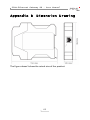
1
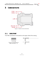
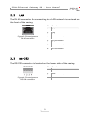
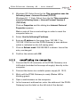
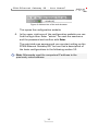
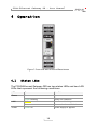
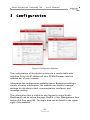
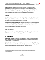
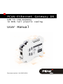
PCAN-Ethernet Gateway DR
CAN to LAN Gateway
in DIN rail plastic casing
User Manual
Document version 1.4.0 (2015-06-01)
PCAN-Ethernet Gateway DR – User Manual
Products taken into account
Product Name
Model
Part Number
PCAN-Ethernet Gateway DR
Industry
IPEH-004010
All product names mentioned in this document may be the trademarks or registered
trademarks of their respective companies. They are not explicitly marked by „™“and
„®“.
Copyright © 2015 PEAK-System Technik GmbH
Duplication (copying, printing, or other forms) and the electronic distribution of this
document is only allowed with explicit permission of PEAK-System Technik GmbH.
PEAK-System Technik GmbH reserves the right to change technical data without
prior announcement. The general business conditions and the regulations of the
license agreement apply. All rights are reserved.
PEAK-System Technik GmbH
Otto-Roehm-Straße 69
64293 Darmstadt
Germany
Phone:
Fax:
+49 (0)6151 8173-20
+49 (0)6151 8173-29
www.peak-system.com
[email protected]
Document version 1.4.0 (2015-06-01)
2
PCAN-Ethernet Gateway DR – User Manual
Contents
1 Introduction
1.1 Properties at a Glance
1.2 Prerequisites for Operation
1.3 Scope of Supply
5
5
6
7
2 Connectors
2.1 CAN1/CAN2
2.2 LAN
2.3 RS-232
2.4 Power Supply
8
8
9
9
10
3 Putting into Operation
3.1 First Connection to the PCAN-Gateway
3.1.1
Preparing the Computer
3.1.2
Establishing the Connection
3.2 Basic Configuration
3.2.1
Change Login Data
3.2.2
Setting up CAN
3.2.3
Connecting to a LAN Network
3.3 Installing the Gateway
11
11
11
12
14
14
14
15
17
4 Operation
4.1 Status LEDs
4.2 Reset Button
4.3 Signal Delay
18
18
19
19
5 Configuration
5.1 Structure of the Website
5.1.1
Header
5.1.2
Navigation
5.1.3
General Symbols
20
22
22
22
23
3
PCAN-Ethernet Gateway DR – User Manual
5.2 Status
5.3 Routing
5.3.1
Manage Routes
5.3.2
Add / Edit Route
5.3.3
Scan for Devices
5.4 Filters
5.4.1
Manage Filters
5.4.2
Add / Edit Filter
5.5 Network
5.5.1
CAN
5.5.2
LAN
5.6 Device
5.6.1
Device Configuration
5.6.2
User Management
5.6.3
Software Update
5.7 Help
5.8 Support
24
26
27
29
33
34
34
36
39
39
43
46
47
49
51
52
52
6 Application Examples
6.1 Unidirectional Data Transmission
6.2 Bidirectional Data Transmission
53
53
56
7
60
Technical Specifications
Appendix A
CE-Certificate
62
Appendix B
Dimension Drawing
63
4
PCAN-Ethernet Gateway DR – User Manual
1
Introduction
The PCAN-Ethernet Gateway DR allows the connection of different
CAN busses over IP networks. CAN frames are wrapped in TCP or
UDP message packets and then forwarded via the IP network from
one device to another.
The PCAN-Ethernet Gateway DR provides one LAN connection and
two High-speed CAN interfaces. With its DIN rail casing and the
support of the extended temperature range, the module is suitable
for use in an industrial environment.
The configuration of the device is done via a comfortable web
interface. Besides providing a variety of status information, the
website can directly manage settings for the device itself,
communication interfaces, and message routing.
1.1
Properties at a Glance
ARM9 Freescale iMX257 with 16 kByte Level 1 Cache and
128 kByte internal SRAM
256 MByte NAND Flash and 64 MByte DDR2 RAM
Linux operating system (version 2.6.31)
RS-232 connector for serial data transfer (reserved for future
use)
Connections for CAN, RS-232, and power supply via 4-pole
screw-terminal strips (Phoenix)
Reboot and reset of the device to factory defaults with a reset
button
Configuration of the network interfaces and the message
forwarding through a web interface
5
PCAN-Ethernet Gateway DR – User Manual
Plastic casing (width: 22.5 mm) for mounting on a DIN rail
(DIN-EN 60715 TH35)
LEDs for device status and power supply
Voltage supply from 8 to 30 V
Extended operating temperature range from -40 to 85 °C
(-40 to 185 °F)
CAN Properties:
Two High-speed CAN channels (ISO 11898-2)
Bit rates from 5 kbit/s up to 1 Mbit/s
Compliant with CAN specifications 2.0A (11-Bit ID)
and 2.0B (29-Bit ID)
Galvanic isolation of the CAN channels up to 500 V against each
other, against RS-232 and the power supply
NXP PCA82C251 CAN transceiver
LAN Properties:
Data transmission using TCP or UDP
10/100 Mbit/s bit rate
RJ-45 connector with status LEDs
1.2
Prerequisites for Operation
Voltage supply in the range of 8 to 30 V
6
PCAN-Ethernet Gateway DR – User Manual
1.3
Scope of Supply
PCAN-Ethernet Gateway DR in DIN rail plastic casing
Mating connectors (Phoenix, Type: MSTB 2,5/4-ST BK) for both
CAN channels, RS-232, and power supply
RJ-45 network patch cord (2 m)
Manual in PDF format
Printed quick start guide
7
PCAN-Ethernet Gateway DR – User Manual
2
Connectors
Figure 1: Position of the connectors
2.1
CAN1/CAN2
The CAN connectors are located on the upper side of the casing.
Figure 2: Pin assignment
CAN connector 1 + 2
8
Pin
Function
1
CAN-High
2
CAN-Low
3
CAN-GND
4
CAN-Shield
PCAN-Ethernet Gateway DR – User Manual
2.2
LAN
The RJ-45 connector for connecting to a LAN network is centered on
the front of the casing.
Figure 3: Pin assignment
RJ-45 connector
2.3
Pin
Function
1
TxD
2
TxD
3
RxD
4
not connected
5
not connected
6
RxD
7
not connected
8
not connected
RS-232
The RS-232 connector is located on the lower side of the casing.
Figure 4: Pin assignment
RS-232 connector
9
Pin
Function
1
GND
2
RxD
3
not connected
4
TxD
PCAN-Ethernet Gateway DR – User Manual
2.4
Power Supply
The connection for the power supply is located on the lower side of
the casing.
Figure 5: Pin assignment
Power connector
10
Pin
Function
1
GND
2
not connected
3
Vbat (8 - 30 V)
4
Shield (top hat rail potential)
PCAN-Ethernet Gateway DR – User Manual
3
Putting into Operation
The PCAN-Ethernet Gateway DR is configured via a web interface.
Therefore, the module must be connected via LAN to a computer,
located in the same logical network as your gateway
(192.168.1.xxx).
3.1
First Connection to the PCAN-Gateway
During initial operation or after resetting to factory defaults, you
must pre-configure the PCAN-Gateway for your LAN. The default
login data is written on the label on the left side of the PCANGateway. Proceed as described in the following subsections:
3.1.1
Preparing the Computer
Your computer must be configured with an appropriate IP
address to connect to the device via LAN. To determine your IP
address and to change it if necessary, follow these steps.
1.
Windows 8.1, 7, Vista: Click on Start > Control Panel >
Network and Internet > Network and Sharing Center.
Windows XP: Click on Start > Control Panel >
Network and Internet > Network Connections (continue
with step 3).
2.
On the left side, open the overview of the network adapters
via the following link:
Windows 8.1, 7: Change adapter settings
Windows Vista: Manage network connections
3.
Do a right-click on the adapter that will be used for the
connection to the PCAN-Gateway and select Properties.
The dialog box Properties of LAN connection appears.
11
PCAN-Ethernet Gateway DR – User Manual
4.
Windows XP: Select from the list This connection uses the
following items > Internet Protocol (TCP/IP)
Windows 8.1, 7, Vista: Select from the list This connection
uses the following items > Internet Protocol Version 4
(TCP/IPv4).
Click on Properties and the dialog box Internet Protocol
Properties appears.
Make a note of the current settings in order to reset the
computer later on.
5.
Select Use the following IP address.
6.
Enter an IP address in the range from 192.168.1.1 to
192.168.1.254 (but not the PCAN-Gateway's own address
which is indicated on the left casing side).
7.
Click on Subnet mask. 255.255.255.0 is shown. Leave this
entry unchanged.
8.
Confirm the entries with OK.
3.1.2
Establishing the Connection
1.
Connect the RJ-45 connector of the PCAN-Gateway via a
LAN cable (included in the scope of supply) directly to the
computer.
2.
Connect the device to a suitable power supply (8 - 30 V).
3.
Wait until the PCAN-Gateway is ready (Status LED is
blinking green).
4.
Open a web browser on the computer.
5.
In the browser's address bar, enter the address of the PCANGateway (see the label on the left side of the device).
12
PCAN-Ethernet Gateway DR – User Manual
Figure 6: Address bar of the web browser
This opens the configuration website.
6.
In the upper right area of the configuration website you can
find the login area. Enter “admin“ for each the username
and the password and confirm with Enter.
The restricted area appears and you can start setting up the
PCAN-Ethernet Gateway DR. You can find a description of
the basic configurations in the following section 3.2.
Note: Afterwards reset the computers IP address to the
previously noted address.
13
PCAN-Ethernet Gateway DR – User Manual
3.2
Basic Configuration
Change your login data first and then set up the PCAN-Gateway
connection to the LAN network.
3.2.1
Change Login Data
1.
Open the page Device > User Management.
2.
Change the login data on this page. Create a new username
and a new password.
To ensure a minimum level of security, the password should
have at least 8 characters. If possible, use letters, numbers,
and special characters.
Important notice: Login data is confidential! Do not act carelessly and leave your system open to attack. Never deposit the
login data in any form on the Internet or make it easily
accessible. Do not give the new login data carelessly to third
parties or send it by e-mail.
3.2.2
Setting up CAN
Enter the following settings to configure the CAN channels:
Open the page Network > CAN.
1.
Bit rate: For setting the bit rate, click the drop-down menu
and select the value that is used on the connecting CAN bus.
2.
Listen-Only-Mode: If the PCAN-Gateway should act as a
pure observer, not affecting the data traffic, Listen-OnlyMode must be enabled. Activate Listen-Only-Mode with a
click on the checkbox.
Confirm the entries with Save Settings.
14
PCAN-Ethernet Gateway DR – User Manual
3.2.3
Connecting to a LAN Network
Accommodate the IP address data of the PCAN-Gateway to the
future LAN network.
Open the page Network > LAN.
Automatic Address Assignment via DHCP
1.
If the future LAN network uses DHCP (Dynamic Host
Configuration Protocol), the PCAN-Gateway IP address and
Subnet mask are assigned automatically. Enable DHCP to
use this feature.
2.
Confirm the entry with Save Settings.
You are automatically logged out and the basic setup of the
device is now completed. When the PCAN-Gateway is
installed in the LAN, it automatically receives its new
address data via DHCP.
Note: DHCP is not recommended, because it is necessary to
know the IP address of the device to access the configuration
website. Furthermore the IP address may change after a restart
of the device or the DHCP server. In this case the existing
routes won't work.
15
PCAN-Ethernet Gateway DR – User Manual
Manual Address Assignment
1.
If the LAN network does not provide DHCP, enter the
address data that the PCAN-Gateway should use in the LAN
network at the bottom of the page: IP address and Subnet
mask. The gateway address can optionally be specified.
2.
Confirm the entry with Save Settings.
You are automatically forwarded to the new IP address
under which the PCAN-Gateway is now reachable. The basic
setup of the device is now completed.
16
PCAN-Ethernet Gateway DR – User Manual
3.3
Installing the Gateway
Do the following to connect the PCAN-Ethernet Gateway DR to
an IP network (Ethernet):
1.
Mount the PCAN-Ethernet Gateway DR at the appropriate
position on the DIN rail by placing it at the top of the rail and
snapping it to the bottom.
2.
Connect each of the two CAN ports with the affiliated CAN
network.
Note: A High-speed CAN bus needs to be electrically terminated on both ends using resistors of 120 Ω. The device
does not have an internal termination.
3.
Connect the RJ-45 connector using a LAN cable to the IP
network.
4.
Connect the PCAN-Ethernet Gateway DR to a suitable power
supply (8 - 30 V).
The PCAN-Gateway starts automatically. When the status LED is
blinking green the device is ready and the current configuration is
executed.
Note: In case of a dynamic address assignment via DHCP, the
new IP address must first be determined. Commercial routers
list all connected devices with their current IP address.
17
PCAN-Ethernet Gateway DR – User Manual
4
Operation
Figure 7: Front side with LEDs and Reset button
4.1
Status LEDs
The PCAN-Ethernet Gateway DR has two status LEDs and two LAN
LEDs that represent the following conditions:
LEDs
Status
LAN
Power
Status
Condition
Green on
System start
Green blinking
Ready for operation
Yellow on
Data is transmitting
Green on
Connection is established
Green on
Power supply is applied
18
PCAN-Ethernet Gateway DR – User Manual
4.2
Reset Button
If the PCAN-Ethernet Gateway DR is no longer available due to an
incorrect configuration, the device can be reset to factory defaults
using the Reset button.
To perform a reset, press with a paper clip for example into the
small hole on the front side of the casing. Press for 1 second to
restart the device. Press for more than 5 seconds to reset the PCANGateway to factory defaults.
With a reset to the factory defaults, the IP address and the login
data are reset to the initial value (see the label on the left side of the
PCAN-Gateway). Afterwards you can perform a reconfiguration of
the PCAN-Gateway (see chapter 3 on page 11).
4.3
Signal Delay
The signal delay between the CAN connection and LAN may vary.
The transmit time of the signal in the IP network depends on the expansion and structure of the network as well as the configuration of
the message forwarding. Therefore a fixed value cannot be
specified.
19
PCAN-Ethernet Gateway DR – User Manual
5
Configuration
Figure 8: Configuration Website
The configuration of the device is done via a comfortable web
interface. Enter the IP address of your PCAN-Gateway into the
address bar of your browser.
Afterwards the configuration website opens. Besides providing a
variety of status information, the website can directly manage
settings for the device itself, communication interfaces, and
message routing.
The information that is visible to non logged in users (Public
Dashboard) can be set on the page Device > User Management (see
section 5.6.2 on page 49). The login area can be found to the upper
right of the website.
20
PCAN-Ethernet Gateway DR – User Manual
Enter your username and password, then press Enter . After
logging in, you will have access to the 7 main areas of the website:
Status, Routing, Filters, Network, Device, Help, and Support.
Note: For full functionality and an optimal representation of the
website, we recommend one of the following Internet
browsers: Internet Explorer 8 or higher, Mozilla Firefox, Safari,
Opera, or Chrome.
The storing of cookies by the browser is required to access the
website.
Some features of this website require JavaScript. Please enable
support for this scripting language if a prompt appears on the
website.
21
PCAN-Ethernet Gateway DR – User Manual
5.1
5.1.1
Structure of the Website
Header
The header area of the website displays the product name, as well
as a user defined name and description that can be set on the
Device > Configuration page. This information is used to identify the
device.
5.1.2
Navigation
On the left side is the main navigation menu:
The main pages (Status, Routing, Filters, Network, Device, Help,
and Support) display general information
The subpages of Network and Device provide configuration
options for the device and for the network
The subpages of Routing can be used to add, manage, edit or
delete, as well as to search for other devices in the network
The subpages of Filters can be used to add, edit, or delete filters
The links in the control box (below the menu) perform additional
website and device functions
Refresh: Clicking Refresh will perform a page reload, for
example to update the current route status
Note: The information displayed on the website is not updated
automatically by default.
Auto Refresh On / Off: When you activate this function by left
clicking the link, the website will begin to automatically update
the information on the page every 10 seconds. You can
manually turn this function off by left clicking the link again.
22
PCAN-Ethernet Gateway DR – User Manual
Navigating away from the current page will automatically
deactivate this function too
Status LED On: The status LED on the device will light up for
approximately 10 seconds. This function can be used to identify
the device
Reboot Device: Use this link to restart the device. During this
process, the PCAN-Gateway will be unreachable for a short time
The red framed Info box at the end of the navigation lists important
information about the current configuration.
5.1.3
General Symbols
The configuration website uses a variety of different symbols and
icons to convey general information that is valid for many
situations.
In some cases, additional information is displayed as a tooltip when
you hover the mouse cursor over the icon.
LED Symbol
Meaning
ON / active
OFF / inactive
Warning! The execution / function is prevented. The problem is
well known and can be eliminated.
Attention! An error prevents the execution / function.
23
PCAN-Ethernet Gateway DR – User Manual
5.2
Status
On the Status page the current device configuration is displayed.
Device Information:
In this box the product name, the order number, and the serial
number of the device are displayed. This information can be used to
uniquely identify the device.
On the Device page you will find detailed information about the
device
CAN Interfaces:
For each CAN channel the status, bit rate, and the setting of the
Listen-Only-Mode are displayed.
The CAN interfaces can be configured on the Network > CAN
page.
LAN Interface:
This box displays the LAN interface settings. IP address, Subnet
mask, and gateway are adjustable. The MAC address cannot be
changed. Each device receives a unique MAC address during the
manufacturing process, which can be used for identification.
The LAN interface can be configured on the Network > LAN
page
24
PCAN-Ethernet Gateway DR – User Manual
Defined Routes:
Here, each message forwarding is displayed with its basic
information. For each of these, the index, the status, the used
transmission protocol, the source and destination, as well as the
used filters are specified.
On the Routing > Manage Routes page, the routes can be
managed, edited, and deleted
On the Routing > Add Route page new message forwarding
instances can be created
Defined Filters:
This box contains an overview of all defined filters with basic
information. Starting with the index, every filter is displayed with its
usage, name, type, and mode.
On the Filter > Manage Filters page, the filters can be managed,
edited, and deleted
On the Filter > Add Filter page new filters can be created
25
PCAN-Ethernet Gateway DR – User Manual
5.3
Routing
Routing displays basic information about the created routes and
PCAN-Gateways detected on the network.
Defined Routes:
Here, each message forwarding is displayed with its basic
information. For each of these, the index, the status, the used
transmission protocol, the source and destination, as well as the
used filters are specified.
On the Routing > Manage Routes page, the routes can be
managed, edited, and deleted
On the Routing > Add Route page new message forwarding
instances can be created
Detected Devices:
This table shows all PEAK-System gateways that were detected
during the last network broadcast scan. If no other devices are
currently in the network or no scan has been performed, this table
will not be shown.
Each PCAN-Gateway is displayed with its product name, the custom
device name, MAC address, and serial number. This information
can be used to identify the device. In addition, the IP address and a
small icon of the device are displayed. With a left-click the
configuration website of this device can be opened in a new tab.
On the Routing > Scan for Devices page, a search for available
devices on the network can be performed
Note: When changing the network topology, the list is not
updated automatically. If a device is removed from the network,
it will remain visible in the list of detected devices until the scan
is performed again and the list is updated.
26
PCAN-Ethernet Gateway DR – User Manual
5.3.1
Manage Routes
On the page Routing > Manage Routes the message forwarding
instances are listed with basic information and control options. For
each of these, the index, the status, the used transmission protocol,
the source and destination, as well as the used filters are specified.
Index: For saving routes, the PCAN-Gateway uses a table with 8
rows that are addressed with the unique index.
Filter: Hover the filter icon with the mouse cursor to display a list of
the attached filters. The list refers to the indices of the filters.
Perform a left-click on the icon to open the page Filters > Manage
Filters with the corresponding rows highlighted.
Status: The LED indicates the status of a route.
LED Symbol
Meaning
The route is inactive.
The route is active and connected with the remote site.
Warning! The route is active but not connected with the remote
site.
PCAN-Gateway handshake is inactive.
Source / Destination: The source and the destination depend on the
direction of the message forwarding.
In a Receive route the PCAN-Gateway receives data via the IP
interface and forwards it to a CAN channel. The IP address is
displayed in this case as "Local IP".
In a Send route the data of a CAN channel is forwarded over the IP
interface. By left-clicking the IP address of the receiver, its configuration website can be opened.
27
PCAN-Ethernet Gateway DR – User Manual
Protocol: Routes can use TCP or UDP as the transmission protocol
in the IP network.
TCP (Transmission Control Protocol) establishes a connection
between two participants and monitors their communication. If data
packets are lost for example, they are retransmitted.
UDP (User Datagram Protocol) sends the data packets directly into
the network without establishing a connection. With this protocol,
error free transmission is not guaranteed. The advantage UDP has
over TCP is the lower demand on performance.
Control Elements:
Symbol
Meaning
Switch ON / Switch OFF (depending on the current state)
Delete
Edit
ON/OFF: Use the "ON / OFF" switch to activate or deactivate a route.
Delete: Click on the trash can icon to remove the route.
Edit: Click on the pencil icon to edit the route. The route is loaded
into the forms of the page Routing > Add Route. The same input
and configuration options are available there. Detailed information
can be found in the following chapter 5.3.2.
Add Route : This button opens the Routing > Add Route page on
which you can set up a new message forwarding instance.
28
PCAN-Ethernet Gateway DR – User Manual
Additional information:
Each route is provided with additional information about its
connection and data transfer status. This additional information can
be viewed by clicking on the triangle icon located on the right edge
of the route.
In Expert mode (see chapter 5.6.2 Device> User Management)
detailed connection status information are displayed. With the
Reset button you can reset the values of the route to 0.
5.3.2
Add / Edit Route
On the Routing > Add Route page you can set up a new route.
Similarly, an existing route can be edited via the form displayed. For
this, the current settings are loaded into the form fields. Editing a
route is done via the page Routing > Manage Routes.
For saving routes, the PCAN-Gateway uses a table with 8 rows that
are addressed with a unique index. If a new route to be set up, the
lowest free index will be assigned. Because of that, only up to 8
routes can be created regardless of the status. Then the Add Route
function is no longer available.
Route Direction:
When you create a route, you should start with the selection of
direction since the following input and output fields are determined
by this.
Receive IP > CAN: In a Receive route the PCAN-Gateway receives
data via the IP interface and forwards it to a CAN channel. The IP
address shown in this case is "Local IP". The configuration of the
local IP interface is done on the Network > LAN page.
29
PCAN-Ethernet Gateway DR – User Manual
Send CAN > IP: In a Send route the data of a CAN channel is
forwarded over the IP interface. If other PCAN-Gateways were
discovered during a broadcast scan, they can be selected for the
destination of the route. On the page Routing > Scan for Devices
you can search for other PCAN-Gateways in the network.
Status:
Use this setting to determine the state of the route after it is created.
Ticking the checkbox will have the effect of immediately activating
the route after the completed form is saved.
PCAN-Gateway handshake off: (Expert mode only) If this checkbox
is active, no handshake will be performed and therefore no status
information will be gathered for this route. Use this option for
communication with your own application *.
CAN Interface:
Choose one of the available CAN channels. The configuration of the
CAN interfaces is done on the page Network > CAN.
IP Interface:
IP-Address Source: This field only appears when PCAN-Gateways
were detected during a network broadcast scan and the direction
“Send CAN> IP" is selected.
Select the desired device from this drop-down menu. The following
IP address is automatically set to the appropriate value. If you prefer
to enter the IP address yourself, select "Manual Input".
*
For information about the data protocol see the PCAN-Gateway developer
documentation.
30
PCAN-Ethernet Gateway DR – User Manual
IP Address: Enter the IP address (IPv4) of the destination device. It
should be noted that only values from 0 to 255 may be used and
certain address ranges are reserved.
In the first field, enter a value less than 224, since addresses
starting from this value are reserved for Multicast messages
Depending on the Subnet mask, the highest device address is
reserved for broadcast messages. For the Subnet mask
255.255.255.0 and the network address 192.168.1.xxx, the
reserved address would be: 192.168.1.255
Depending on the Subnet mask the lowest device address is
reserved for messages that are addressed to the entire network.
For the Subnet mask 255.255.255.0 and the network address
192.168.1.xxx, the reserved address would be: 192.168.1.0
Port: Enter a port between 1024 and 65535. Values below 1024 are
reserved for various system services and must therefore not be
used.
Protocol: Select which transmission protocol should be used by the
route in the IP network.
TCP (Transmission Control Protocol) establishes a connection
between two participants and monitors their communication. If data
packets are lost for example, they are retransmitted.
UDP (User Datagram Protocol) sends the data packets directly into
the network without establishing a connection. With this protocol,
error free transmission is not guaranteed. The advantage UDP has
over TCP is the lower demand on performance.
Note: Any combination of the IP address, port, and protocol can
only be used once.
31
PCAN-Ethernet Gateway DR – User Manual
Frames per Packet: This value specifies how many CAN frames are
transmitted per IP packet. The higher the value, the greater the
delay in the transmission of CAN messages. However, the demand
on performance is lower in this case. This selection is only available
for Send routes when using the UDP protocol.
Finally you can create a new route with the Add Route button or
save the changes after editing with the Save Settings button.
Note: Transferring data between 2 PCAN-Gateways always
consists of a Send and a Receive route. Note that both should
use the same transmission protocol (TCP or UDP) and the same
port.
Filter:
The defined filters are listed in this formula. A single one can be
attached or detached to Send routes via the radio buttons. If Expert
mode is active, the radio buttons will be replaced with checkboxes
and multiple filters can be selected.
Filters are joined with: This property specifies how multiple filters
are linked. If you use several Whitelist filter, you should choose
Logical OR. If you attach multiple Blacklist filter to a single route, the
selection Logical AND is recommended.
Note: A single Range filter is realized with a composition of
multiple Mask filters. The Joined Filters property will also affect
this.
32
PCAN-Ethernet Gateway DR – User Manual
5.3.3
Scan for Devices
Using the Routing > Scan for Devices page a broadcast message
can be sent to the IP network, to which all PCAN-Gateway products
report. From the obtained information, a list of available devices is
created. The detected devices can then be used as target
destinations while creating or editing routes.
Note: When changing the network topology, the list is not
updated automatically. If a device is removed from the network,
it will remain visible in the list of detected devices until the scan
is performed again and the list is updated.
Detected Devices:
This table shows all PEAK-System gateways that were detected
during the last network broadcast scan. If no other devices are
currently in the network or no scan has been performed, this table
will not be shown.
Each PCAN-Gateway is displayed with its product name, the custom
device name, MAC address, and serial number. This information
can be used to identify the device. In addition, the IP address and a
small icon of the device are displayed. With a left-click the
configuration website of this device can be opened in a new tab.
Perform Scan: By clicking on the Perform Scan button, the list of
available devices is updated. The scan takes a short time. Please
wait until you are forwarded.
33
PCAN-Ethernet Gateway DR – User Manual
5.4
Filters
Filters are used to filter CAN messages by their ID. It is possible to
create up to 32 of them. Each filter can be attached to multiple Send
routes via the page Add Route or Edit Route.
The page Filters displays basic information about the created filters.
Defind Filters:
This box contains an overview of all defined filters with basic
information. Starting with the index, every filter is displayed with its
usage, name, type, and mode.
On the Filters > Manage Filters page, the filters can be managed,
edited, and deleted
On the Filters > Add Filter page new filters can be created
5.4.1
Manage Filters
On the page Filters > Manage Filters the existing filters are listed
with basic information and control options. Each of them is
specified with its index, usage, name, type, and mode.
Index: For saving filters, the PCAN-Gateway uses a table with 32
rows that are addressed with this unique index.
Usage: The badge on the left shows how many times the filter is
used. The information to which routes it is attached to, is
displayed as a tooltip when hovering with the mouse cursor.
The list refers to the indices of the routes. If you click on the
badge, the page Manage Routes will be opened with the
corresponding routes highlighted.
34
PCAN-Ethernet Gateway DR – User Manual
Name: While creation a name can be assign to a filter. It can be
used for identification while managing the filters or attaching
them to routes.
Type: This column displays the filter type (Range or Mask) and
the used CAN ID mode (11- or 29 Bit). Detailed information can
be found in chapter 5.4.2 Add / Edit Filter.
Mode: The filter mode (Blacklist or Whitelist) indicates if the
defined filter is inverted or not.
Control Elements:
Symbol
Meaning
Delete: Click the trash icon to remove the filter. If it is attached to
one or more routes, it will be automatically detached
Edit: Click on the pencil icon to edit the filter. The filter is loaded
into the forms of the page Filters > Add Filter. The same input and
configuration options are available there. Detailed information
can be found in chapter 5.4.2 Add / Edit Filter
Add Filter: The button below the information table opens the Filters
> Add Filter page on which you can set up a new filter. It is not
available if the limit of 32 filters is reached.
Detailed Information:
The filters are provided with detailed information. It can be
displayed by clicking on the triangle icon located on the right edge
of each filter row.
35
PCAN-Ethernet Gateway DR – User Manual
5.4.2
Add / Edit Filter
On this page you can set up a new filter. Similarly, an existing one
can be edited via the form displayed. For this, the current settings
are loaded into the form fields. Editing a filter is done via the page
Filters > Manage Filters.
For saving filters, the PCAN-Gateway uses a table with 32 rows that
are addressed with a unique index. If a new filter to be set up, the
lowest free index will be assigned. Because of that, only up to 32
filters can be created regardless of their status. If the limit is
reached, the Add Filter function is no longer available.
Type and ID Mode:
When you create a filter, you should start with the selection of the
type and ID mode since the following input and output fields are
determined by this. The filter types Range and Mask specify how
the CAN IDs to be filtered are defined.
The ID modes specify if the CAN message will be a Standard frame
with an 11 Bit identifier or an Extended frame with a 29 Bit
identifier. This changes the ID value range that can be entered in the
following forms.
Mode:
The mode indicates how the defined filter is interpreted.
Whitelist: A filter using this mode will transmit every CAN
message whose ID matches the filter specifications.
Blacklist: If this mode is selected, the filter will be inverted. That
means every message with a CAN ID that matches the filter
specifications will not be transmitted.
36
PCAN-Ethernet Gateway DR – User Manual
Type Range:
If the filter type Range was chosen, a lower and an upper limit have
to be specified to set the range. This can be done via the slider
(JavaScript support required) or with the input forms.
From: This value marks the lower limit of the filter range.
To: This value marks the upper limit of the filter range.
While entering the values the following should be considered:
The values are entered in hexadecimal format. Invalid input will
be ignored
The From value has to be lower than the To value
Type Mask:
The working principle of this acceptance filtering is based on the
SJA1000 CAN controller. Detailed information can be found in the
NXP Application Note AN97076 - SJA1000 Stand-alone CAN
controller chapter 4.1.2.
The ID of the CAN message to be transmitted is compared bitwise
with the Acceptance Code value. The Acceptance Mask specifies
which bit positions are relevant.
0 = relevant. The CAN ID at the corresponding bit position has to
match the value of the Acceptance Code.
1 = not relevant. The CAN ID at the corresponding bit position
does not matter.
In contrast to the original implementation, the PCAN-Gateway Mask
filter only looks at the CAN ID. It cannot process any data bytes or
the RTR flag.
37
PCAN-Ethernet Gateway DR – User Manual
The size of the Acceptance Mask and Acceptance Code depends on
the ID mode selection above and can be 11 Bit for Standard with a
range of 0 to 7FF or 29 Bit for Extended with a range of 0 to
1FFFFFFF.
Example for 11 Bit identifiers:
IDs
Meaning
0
1
1
1
1
0
1
1
1
1
1
Acceptance-Code
1
1
1
0
0
0
0
1
1
0
1
Acceptance-Mask
X
X
X
1
1
0
1
X
X
1
X
CAN messages with an ID
matching this binary
value, are accepted. X
means that this bit
position does not matter.
MSB
LSB
Name:
A name with up to 50 characters can be assign to a filter. It can be
used for identification while managing filters or attaching them to
routes.
Description:
You can enter additional information with a length of 200 characters
for each filter. This text is only available on the page Filters > Add /
Edit Filter and Filters > Manage Filters.
Finally you can create the new filter with the Add Filter button or
save the changes after editing with the Save Settings button.
38
PCAN-Ethernet Gateway DR – User Manual
5.5
Network
The Network page provides information about the current configuration of available communication interfaces.
CAN Interfaces:
For each CAN channel the status, the bit rate, and the setting of the
Listen-Only-Mode are displayed.
The CAN interfaces can be configured on the Network > CAN
page. In addition, this page provides detailed information about
the interfaces
LAN Interfaces:
This box displays the LAN interface settings. IP address, Subnet
mask, and gateway are adjustable. The MAC address cannot be
changed. Each device receives a unique MAC address during the
manufacturing process, which can be used for identification.
The LAN interface can be configured on the Network > LAN
page
5.5.1
CAN
The Network > CAN page displays the current settings of the CAN
interfaces as well as options to configure them. Information about
the status, Listen-Only-Mode, and the bit rate is displayed for each
CAN channel.
Channel: The channel number of the CAN interface. This number is
used to select the intended interface while creating a route.
39
PCAN-Ethernet Gateway DR – User Manual
Status: The LED indicates the state of the CAN channel.
LED Symbol Status
Meaning
Active
The channel is active and functional.
Inactive
The channel is inactive.
Error Active
Errors were detected on the BUS.
The CAN controller’s error count is lower than 128.
(BUSLIGHT)
Error Passive Errors were detected on the BUS.
The CAN controller’s error count is greater than 127.
(BUSHEAVY)
Bus Off
Errors were detected on the BUS.
The CAN controller’s error count is greater than 255.
The CAN controller has been switched off.
(BUSHEAVY)
Bit Rate: CAN channel transmission rate. This value should match
that one of the connected CAN bus.
Listen-Only-Mode: The state of the Listen-Only-Mode is represented
by an LED.
LED Symbol
Meaning
Active. The CAN channel is not sending messages, nor is it
answering incoming messages (Acknowledge).
Inactive
Additional Information: Furthermore status information and user
defined notes are available for each channel. Click the triangle icon
on the right edge of the list item to view the information. With the
Reset button you can reset the CAN channel.
In Expert mode, (See chapter 5.6.2 Device > User Management)
further detailed information is displayed.
40
PCAN-Ethernet Gateway DR – User Manual
CAN Channel Configuration:
Each channel is handled and configured by a separate form.
Settings can be saved by clicking the Save Settings button located
underneath the form.
Activate / Deactivate: (Expert mode only) Use the Checkbox to
activate or deactivate the CAN channel.
Bit Rate Selection: For setting the bit rate, click the drop-down
menu and select the value that is used on the connected CAN bus.
Custom Bit Rate: (Expert mode only) By clicking on this checkbox, a
form for configuring a custom transmission rate can be opened. For
details, see the following section Configuring Custom Bit Rates.
Listen-Only-Mode: If the PCAN-Gateway should act as a pure
observer, not affecting the data traffic, Listen-Only-Mode must be
enabled. Activate Listen-Only-Mode with a click on the checkbox.
User Notes: Each CAN channel can have a comment. The maximum
length of the comment is 125 characters.
41
PCAN-Ethernet Gateway DR – User Manual
Configuring Custom Bit Rates
In Expert mode, you can create a custom bit rate and configure the
sample point. Via the Custom Bit Rate checkbox, the necessary
input fields for entering the register values of the CAN controller are
displayed.
The first four fields have a direct impact on the bit rate and the
sample point.
Bit Rate Prescaler: With this input field, the radio of CPI clock and
serial clock frequency is set. It accepts values from 1 to 256.
Phase Segment 1 & 2: The phase segments are used to compensate
edge phase errors at the beginning and end of the bit. Phase
Segment 1 expects an input from 1 to 8 and Phase Segment 2
accepts values from 2 to 8.
Propagation Segment: This time segment is used to compensate
the signal delays over the network and can accept values from 1 to
8.
Calculated bit rate: The form checks your entries and calculates the
transmission rate using the following formula:
The segment Synchronization is always 1 and is used for the
synchronization of each bus node. The sampling time (sample
point) is determined via Time Segments 1 and 2. Time Segment 1
consists of Phase Segment 1 and the Propagation Segment. Their
42
PCAN-Ethernet Gateway DR – User Manual
sum must be at least 4. Time Segment 2 is defined by Phase
Segment 2.
Figure 9: Bit Timing
Note: When entering values the resulting transmission rate is
automatically calculated in real time. If the values are incorrect,
or the calculated bit rate is beyond the limits of the CAN
transceiver (5 kbit/s to 1 Mbit/s), the data can not be saved.
Re-Synch. Jump Width (1 – 4): The Resynchronization Jump Width
defines the maximum extension or shortening of the Phase
Segments for the signal resynchronization. This value is not used
for the calculation of the bit rate. It accepts values from 1 to 4.
By clicking on the Save Settings button you can save your
previously defined bit rate.
5.5.2
LAN
The Network > LAN page displays the current settings of the LAN
interface and provides options for configuration.
43
PCAN-Ethernet Gateway DR – User Manual
LAN Interface
In this box the settings of the LAN interface will be displayed. IP
address, Subnet mask, and gateway are adjustable. The MAC
address cannot be changed. Each device receives a unique MAC
address during the manufacturing process, which can be used for
identification.
LAN Address Settings
The LAN interface can be configured by using the form underneath
the general information overview. Settings can be saved by clicking
the Save Settings button located below the form.
DHCP: If the IP network uses DHCP (Dynamic Host Configuration
Protocol), the PCAN-Gateway IP address, Subnet mask, and
gateway address are assigned automatically. Otherwise, you must
manually enter the information. Switch DHCP on if required
(Enable).
Note: DHCP is not recommended, because it is necessary to
know the IP address of the PCAN-Gateway to access the
configuration website. Furthermore the IP address may change
after a restart of the device or the DHCP server. In this case the
existing routes won't work.
IP Address: Enter the IP address (IPv4) of the LAN interface. It
should be noted that only values from 0 to 255 may be used and
certain address ranges are reserved.
In the first field, enter a value less than 224, since addresses
starting from this value are reserved for Multicast messages
Depending on the Subnet mask, the highest device address is
reserved for broadcast messages. For the Subnet mask
44
PCAN-Ethernet Gateway DR – User Manual
255.255.255.0 and the network address 192.168.1.xxx, the
reserved address would be: 192.168.1.255
Depending on the Subnet mask the lowest device address is
reserved for messages that are addressed to the entire network.
For the Subnet mask 255.255.255.0 and the network address
192.168.1.xxx, the reserved address would be: 192.168.1.0
Subnet mask: The Subnet mask indicates which part of the IP
address represents the network, and which part represents the
device. This subdivision is achieved by filling in the (binary) Subnet
mask from left to right with the number “1”. The resulting values
for the individual fields are: 0, 128, 192, 224, 240, 248, 252, 254 and
255.
While entering values from left to right, as soon as a value smaller
than “255” is entered, a “0” must follow. For example 255.255.128.0
is valid, while 255.128.255.0 is false.
Gateway: Enter the IP address (IPv4) of the gateway that manages
the IP network. Proceed with the same guidelines as outlined for
local IP address entry. Entering a gateway address is optional.
Note: Please note that after modifying these settings, the
device may not be reachable. Possible causes for this are:
– You have activated DHCP. The IP address of the device is not
known, because it has been acquired dynamically from the
gateway. The address can often be found on a list provided
by the gateway.
– You have changed the part of the address assigned to the
network (see Subnet mask information). In this case the
device is now part of a different network than the one your
computer is a part of. Connecting to the device is only
possible by respectively adapting your computer’s IP
address to the different network that the device is in.
45
PCAN-Ethernet Gateway DR – User Manual
5.6
Device
The Device page displays detailed information about your PCANGateway.
General Product Information: In this area, the product name, order
number, and the serial number of the device are displayed. This
information can be used to uniquely identify the device.
User defined Device Information: The information displayed here
can be defined by the user on the Device > Configuration page. This
information can be used to uniquely identify the device.
Interface Information: This area lists all available communication
interfaces regardless of their state.
Version Information: This area shows different information
concerning versions:
Hardware Version: The hardware version indicates the revision
of the circuit board
Software Version: This version number indicates the version of
the installed software package. This, additionally to the
software, includes the firmware and the website. The software
package can be updated on the page Device > Software Update
Website version: This number indicates the version of the
configuration website that you are currently using. The website
is updated automatically when a software update is processed
46
PCAN-Ethernet Gateway DR – User Manual
5.6.1
Device Configuration
On the Device > Configuration page it is possible to assign a custom
name and description to the device. In addition to that, different
import and export options are available.
Custom Device Name and Description:
Use this form to assign a name and description to the PCANGateway. This will aid in identifying the device among other similar
devices. The name and description will be shown in the header of
the website and other areas.
Name: Enter a name for the device in this field. The maximum
length allowed is 50 characters. Please note: This name is separate
from the product name that is also displayed in the header area of
the website.
Depending on the IP network, it is possible to access the website of
the device by typing this name with a previous http:// in the
address bar of the browser.
Description: Enter a description for the device in this field. The
maximum length allowed is 200 characters.
The entries can be saved by clicking the Save Settings button
located beneath the form.
Import Configuration:
This form allows the importing of locally saved configuration files.
After an import, all communication interfaces and device settings,
as well as the routes and filters are restored. The current
configuration is overwritten within that process.
47
PCAN-Ethernet Gateway DR – User Manual
Use the button on the left side to select a configuration file (*. ini).
To start the restoration process, click the Import button located on
the right.
Note: If you import a configuration file from another PCANGateway device that is in the same network, its IP address will
also be imported and loaded. Both devices would then have the
same IP address. This would cause an address conflict and
would result in both devices being non accessible.
In such a case, separate one device from the power supply. The
other device will then become accessible again and its IP
address can be changed manually. This will resolve the address
conflict and both devices can be used again.
Export Configuration:
With the Export button an ini file can be downloaded containing all
device configurations as well as all route and filter settings.
The file can be freely renamed, the contents of the file however
should not be altered. Importing altered configuration files can lead
to failures during the import process. Only valid configuration files
can be used for device restoration.
Reload Default Settings:
With the Reload button you can restore the device to its factory
defaults. During this process the login settings, all device and
communication interface settings along with existing routes will be
restored to the states they were in at the time of product delivery.
The current configuration is overwritten within that process. In
addition, the access data will be reset to the default values (see the
label on the left side of the device). The PCAN-Gateway is then
reachable under the default IP address (192.168.1.10).
48
PCAN-Ethernet Gateway DR – User Manual
5.6.2
User Management
The Device > User Management page provides options for entering
new login credentials, changing and defining the display mode, and
determining what information should be visible on the login page.
Login Settings:
Enter your current login details in the upper part of the form. In the
lower part you can enter a new username and a new password. The
new password must be confirmed in order to exclude accidental
input.
To ensure a minimum level of security, the password should have
at least 8 characters. If possible, use letters, numbers, and special
characters.
Save your inputs with the Save Settings button.
Important notice: Login data is confidential! Do not act carelessly and leave your system open to attack. Never deposit the
login data in any form on the Internet or make it easily
accessible. Do not give the new login data carelessly to third
parties or send it by e-mail.
Display Mode Setting:
This form provides the opportunity to change the display mode.
Expert mode enables access to more detailed information and
professional settings. Interpreting this information and using these
features requires advanced knowledge of TCP/IP, CAN, and the
message forwarding of the PCAN-Gateways. This setting is valid
only for the current session and will be reset with your next login.
49
PCAN-Ethernet Gateway DR – User Manual
Click on the drop-down menu and choose one of the two modes.
Save this setting by clicking the Save Settings button.
Public Dashboard:
This form is responsible for defining what information is visible on
the website to non-logged in users. Only basic status information
can be made visible, configuration options cannot be unlocked
publicly.
Activate or deactivate the checkboxes to toggle the visibility of their
corresponding information. Confirm your choices with the
Save Settings button.
50
PCAN-Ethernet Gateway DR – User Manual
5.6.3
Software Update
Initiating a software update will update the firmware, software, as
well as the configuration website. The currently installed software
package version is indicated by the software version number. This
number can be found on this page Device > Software Update itself
as well as on the Device page.
Current product updates can be downloaded on the PEAK-System
website (www.peak-system.com). Please make sure to download
the correct package for your device. Every version of the PCANGateway product family has a separate download package.
It's recommended to backup the current configuration before
performing a software update or downgrade. The current settings
may get lost if they are not supported by the software package to be
installed or if a failure like a power cut happens.
Perform a software update:
1.
Use the button on the left to choose the software package
(*.tar).
2.
Start the process with the Start Software Update button.
Please note: In order to prevent conflicts all CAN interfaces
as well as all created routes will be put on standby.
3.
After the software update has completed the device will
reboot. You will be forwarded to the login page in which
case the process was successful and all routes and CAN
interfaces have been reactivated.
Note: If the update process was interrupted, you will have to
restart the device in order to reactivate the routes and CAN
channels. Use the Reboot Device link located near the bottom
of the main navigation. Alternatively you can use the physical
Reset button located on the device itself.
51
PCAN-Ethernet Gateway DR – User Manual
Note: Export your current configuration, if you like to
downgrade to an older software package. The current settings,
routes, and filters may get lost.
5.7
Help
The Help page contains the complete help information available for
your Gateway’s Configuration web site. It is nearly identical to
chapter 5 of the PDF documentation.
Question mark icons are located next to every page title, clicking on
one will open a corresponding help page.
5.8
Support
On the Support page you will find links to product documentation
(German and English) as well as contact information of PEAKSystem Technik GmbH.
52
PCAN-Ethernet Gateway DR – User Manual
6
Application Examples
The PCAN-Ethernet Gateway DR allows the connection of different
CAN busses over IP networks. CAN frames are wrapped in TCP or
UDP message packets and then forwarded via the IP network from
one device to the other. This makes it possible for CAN networks to
connect to each other over large distances.
6.1
Unidirectional Data Transmission
For unidirectional data transmission the message traffic from CAN
bus A is to be forwarded to CAN bus B via a LAN network.
Necessary for this are two PCAN-Ethernet Gateways DR and the
creation of a route on each device.
In this example Gateway 1’s IP address is 192.168.1.201 and it is
connected to CAN bus A via CAN channel 1. Gateway 2’s IP address
is 192.168.1.202 and it is connected to CAN bus B via CAN channel
2.
Creating a Send Route:
Incoming messages from Gateway 1 are to be transferred into the
LAN network. For this, a Send route with the following values must
be created.
53
PCAN-Ethernet Gateway DR – User Manual
Gateway 1 > Send Route
Route Direction
Send: CAN > IP
Status
Activate
CAN
Channel 1 (connected to CAN bus A)
IP Interface
IP-Address
192.168.1.202 (address of Gateway 2)
Port
50000
Protocol
TCP
After saving, the route on Gateway 1 will be displayed on the
Routing > Manage Routes page as follows.
Creating a Receive Route
Gateway 2 is to accept the data packets sent via LAN network by
Gateway 1, and pass the containing CAN messages through CAN
channel 2 into CAN bus B. For this, a Receive route with the
following values must be created.
Gateway 2 > Receive Route
Route Direction
Receive: IP > CAN
Status
Activate
IP Interface
Port
50000 (like the Send route)
Protocol
TCP (like the Send route)
CAN
Channel 2 (connected to CAN bus B)
Transferring data between 2 PCAN-Gateways always consists of a
Send and a Receive route. Note that both should use the same
transfer protocol (TCP or UDP) and the same port.
54
PCAN-Ethernet Gateway DR – User Manual
After saving, the route on Gateway 2 will be displayed on the
Routing > Manage Routes page as follows.
A short time after both routes have been created and activated, the
connection will establish. You can interrupt the connection by
deactivating or erasing one of the routes on the Routing > Manages
Routes page.
Note: The putting into operation of a PCAN-Ethernet Gateway
DR is described in detail in chapter 3 Putting into Operation.
Detailed information concerning the creation of routes, as well
as input and selection options, can be found in chapter 5.3.2
Add / Edit Route.
55
PCAN-Ethernet Gateway DR – User Manual
6.2
Bidirectional Data Transmission
For bidirectional data transmission the message traffic occurring
between CAN busses A and B is to be forwarded via the LAN
network. For this two PCAN-Ethernet Gateways DR are needed,
where for each one, a Send and Receive route must be created.
In this example Gateway 1’s IP address is 192.168.1.201 and it is
connected via CAN channel 1 to CAN bus A. Gateway 2’s IP address
is 192.168.1.202 and it is connected via CAN channel 2 to
CAN bus B.
The difference here, when compared with the example in chapter
6.1, is solely that the opposite message forwarding from CAN bus B
to CAN bus A must also be realized.
The Routes on Gateway 1:
Incoming messages from Gateway 1 are to be transferred into the
LAN network. For this, a Send route with the following values must
be created.
56
PCAN-Ethernet Gateway DR – User Manual
Gateway 1 > Send Route A
Route Direction
Send: CAN > IP
Status
Activate
CAN
Channel 1 (connected to CAN bus A)
IP Interface
IP-Address
192.168.1.202 (address of Gateway 2)
Port
50000
Protocol
TCP
Gateway 1 is to accept the data packets sent via LAN network by
Gateway 2, and pass the containing CAN messages through CAN
channel 1 into CAN bus A. For this, a Receive route with the
following values must be created.
Gateway 1 > Receive Route B
Route Direction
Receive: IP > CAN
Status
Activate
IP Interface
Port
25000 (like the Send route B)
Protocol
TCP (like the Send route B)
CAN
Channel 1 (connected to CAN bus A)
After saving, the routes on Gateway 1 will be displayed on the
Routing > Manage Routes page as follows.
The Routes on Gateway 2:
Gateway 2 is to accept the data packets sent via LAN network by
Gateway 1, and pass the containing CAN messages through CAN
57
PCAN-Ethernet Gateway DR – User Manual
channel 2 into CAN bus B. For this, a Receive route with the
following values must be created.
Gateway 2 > Receive Route A
Route Direction
Receive: IP > CAN
Status
Activate
IP Interface
Port
50000 (like the Send route A)
Protocol
TCP (like the Send route A)
CAN
Channel 2 (connected to CAN bus B)
Gateway 2 should transmit incoming message traffic from CAN bus
B into the LAN network. For this a Send route with the following
values must be created.
Gateway 2 > Send Route B
Route Direction
Send: CAN > IP
Status
Activate
CAN
Channel 2 (connected to CAN bus B)
IP Interface
IP-Address
192.168.1.201 (address of Gateway 1)
Port
25000
Protocol
TCP
Transferring data between 2 PCAN-Gateways always consists of a
Send and a Receive route. Note that both should use the same
transfer protocol (TCP or UDP) and the same port.
After saving, the routes on Gateway 2 will be displayed on the
Routing > Manage Routes page as follows.
58
PCAN-Ethernet Gateway DR – User Manual
A short time after all routes have been created and activated, the
bidirectional connection will establish. You can interrupt the
connection by deactivating or erasing one of the routes on the
Routing > Manages Routes page.
Note: The putting into operation of a PCAN-Ethernet Gateway
DR is described in detail in chapter 3 Putting into Operation.
Detailed information concerning the creation of routes, as well
as input and selection options, can be found in chapter 5.3.2
Add / Edit Route.
59
PCAN-Ethernet Gateway DR – User Manual
7
Technical Specifications
Connectors
CAN
2 x Phoenix connector 4-pin *
LAN
RJ-45 socket
RS-232
Phoenix connector 4-pin*
Power
Phoenix connector 4-pin*
CAN
Specification
ISO 11898-2; High-speed CAN
2.0A (standard format) and 2.0B (extended format)
Bit rates
5 kbit/s - 1 Mbit/s
Transceiver
NXP PCA82C251
Galvanic isolation
Isolation of the CAN channels up to 500 V against
each other, against RS-232 and the power supply
Termination
none
Listen-only mode
Separately switchable for both CAN channels
LAN
Protocol
TCP, UDP
Bit rates
10/100 Mbit/s Base-T
Standard
IEEE 802.3
Additional Features
Auto-Sensing with 10/100 Mbit/s
Auto-Crossover
Power supply
*
Supply voltage
8 - 30 V DC
Max. current consumption
360 mA at 8 V
240 mA at 12 V
100 mA at 30 V
Phoenix connector, type: MSTB 2,5/4-ST BK, order no.: 1756298,
www.phoenixcontact.com
60
PCAN-Ethernet Gateway DR – User Manual
Measures
Size
22.5 x 99 x 114.5 mm (W x H x D)
See also dimension drawing Appendix B
on page 63
Weight
105 g
Environment
Operating temperature
-40 - 85 °C (-40 - 185 °F)
Temperature for storage and
transport
-55 - 125 °C (-67 - 257 °F)
Relative humidity
15 - 90 %, not condensing
EMC
EN 55024: 2011-09
EN 55022: 2011-12
EC directive 2004/108/EG
Ingress protection (IEC 60529) IP20
61
PCAN-Ethernet Gateway DR – User Manual
Appendix A
CE-Certificate
62
PCAN-Ethernet Gateway DR – User Manual
Appendix B
Dimension Drawing
The figure doesn’t show the actual size of the product.
63