1
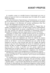
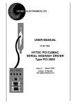
Automatic Modeling and Validation of Pipeline Specifications driven by an
Architecture Description Language
Prabhat Mishray
Hiroyuki Tomiyamaz
Ashok Halambiy
y
Center for Embedded Computer Systems
University of California, Irvine, CA 92697
fpmishra, ahalambi, pgrun, dutt, [email protected]
Abstract
Verification is one of the most complex and expensive tasks
in the current Systems-on-Chip (SOC) design process. Many
existing approaches employ a bottom-up approach to pipeline
validation, where the functionality of an existing pipelined
processor is, in essence, reverse-engineered from its RT-level
implementation. Our approach leverages the system architect’s knowledge about the behavior of the pipelined architecture, through Architecture Description Language (ADL)
constructs, and thus allows a powerful top-down approach
to pipeline validation. This paper addresses automatic validation of processor, memory, and co-processor pipelines described in an ADL. We present a graph-based modeling of
architectures which captures both structure and behavior of
the architecture. Based on this model, we present formal
approaches for automatic validation of the architecture described in the ADL. We applied our methodology to verify
several realistic architectures from different architectural domains to demonstrate the usefulness of our approach.
1
Introduction
Verification is one of the most complex and expensive tasks
in the current System-On-Chip design process. In current
state-of-the-art verification methodology, the architect prepares an informal specification in the form of an English document. The logic designer implements the modules and verifies
them in an ad-hoc manner using simulation test vectors since
there is no golden reference model for validation. A key challenge in today’s design verification is to extract the information from the RT level description and to perform equivalence
checking with the model extracted from the given specification (written in English language). Many existing approaches
([5], [8]) employ a bottom-up approach to pipeline validation,
where the functionality of an existing pipelined processor is,
in essence, reverse-engineered from its RT-level implementation. Hauke et al. [5] compare extracted ISA level description
with the given ISA level specification. Ho et al. [3] extract
This work was partially supported by grants from NSF (MIP-9708067),
DARPA (F33615-00-C-1632), Motorola Inc. and Hitachi Ltd.
Peter Gruny
z
Nikil Dutty
Alex Nicolauy
Inst. of Systems & Information Tech.
Fukuoka 814-0001, Japan
[email protected]
controlled token nets from a logic design to perform efficient
model checking. Our verification technique is complimentary
to these bottom-up approaches. We leverage the system architect’s knowledge about the behavior of the pipelined architecture through ADL constructs, which allows a powerful
top-down approach to pipeline verification using behavioral
knowledge of the pipelined architecture. The ADL description also serves as a golden reference model. Furthermore,
ADL driven verification is a natural choice during rapid design space exploration(DSE) of System-on-Chip(SOC) architectures.
In this paper, we present an automatic validation framework, driven by an ADL. A novel feature of our approach is
the ability to model the pipeline structure and behavior for
the processor, co-processor, as well as the memory subsystem
using a graph-based model. Based on this model we present
formal approaches for automatic validation of the architecture
described in an ADL. We applied our methodology to verify
several realistic architectures from different architectural domains (RISC, DSP, VLIW, and Superscalar) to demonstrate
the usefulness of our approach.
The rest of the paper is organized as follows. Section 2
presents related work addressing ADL-driven validation approaches. Section 3 outlines our approach and the overall flow
of our environment. Section 4 presents a graph-based modeling of processor, memory, and co-processor pipelines. Section 5 proposes several properties that must be satisfied for
valid pipeline specification. Section 6 illustrates validation of
pipeline specifications for several realistic architectures. Finally, Section 7 concludes the paper.
2 Related Work
Recent work on language-driven Design Space Exploration
(DSE) ([1], [2], [4], [12]), uses Architectural Description Languages (ADL) to capture the processor and memory architecture, generate automatically a software toolkit (including
compiler, simulator, assembler) for that architecture, and provide feedback to the designer on the quality of the architecture. It is necessary to verify that the ADL description of
the architecture is well-formed prior to generating software
toolkits. The process of any specification is error-prone and
validation techniques can be used to check for correctness of
the specification. Moreover, changes made to the architecture
during design space exploration may result in incorrect execution of the system and validation techniques can be used to
ensure correctness of the architecture.
The work of Tomiyama et al. [9, 10] is a step in this direction. They defined certain properties that need to be verified to ensure that the architecture description is well-formed.
However, the properties they proposed are applicable to simple processor models. Moreover, they do not demonstrate how
these properties can be applied in SOC verification during design space exploration. Mishra et al. [11] presented a graph
based validation of processor cores and is closest to our approach. Our work extends this technique to validate pipeline
specifications of coprocessors and memory subsystem along
with processor cores.
3
Our Approach
Figure 1 shows the flow in our approach. In our ADL
driven design space exploration scenario, the designer starts
by describing the programmable architecture in an ADL. The
graph model of the architecture can be generated automatically from this ADL description. Several properties are applied automatically to ensure that the architecture is wellformed. To enable rapid DSE the software toolkit can be generated from this golden reference model and the feedback can
be used to modify the ADL description of the architecture.
This golden reference model can also be used to verify the
implementation by performing equivalence checking with the
reverse-engineered description of the implementation..
ADL
SPECIFICATION
English Document
SPECIFICATION
High Level
Description
Property
Checking
Graph Model
Eqivalence
Checking
Feedback
Property
Checking
Feedback
Automatic
Manual
Verification
Reverse
Engineering
RT Design
Simulator
Compiler
Appl
Obj
Figure 1. ADL-driven validation flow
4
Architecture Pipeline Modeling
We develop a graph-based modeling of architecture
pipelines which captures both the structure and the behavior. The graph model presented here can be derived from
a pipeline specification of the architecture described in an
ADL e.g., EXPRESSION [1]. This graph model can capture processor, memory, and co-processor pipelines for wide
variety of architectures viz., RISC, DSP, VLIW, Superscalar,
and Hybrid architectures. Note that it is important to capture
the memory pipeline along with processor pipeline, since any
memory operation exercises both the processor and memory
pipeline structures [13]. In this section we briefly describe
how we model the structure, behavior and the mapping functions between them. The detailed description of the modeling
can be found in [7].
4.1 Structure
The structure of an architecture pipeline is modeled as a
graph GS
GS = (VS ; ES ):
(1)
VS denotes a set of components in the architecture. VS consists of four types of components
VS = Vunit [ Vstore [ Vport [ Vconn
(2)
where Vunit is a set of units (e.g., ALUs), Vstore a set of
storages (e.g., register files, caches), Vport a set of ports, and
Vconn a set of connections (e.g., buses). ES consists of two
types of edges
ES = Edata trans [ Epipeline
(3)
where Edata trans is a set of data-transfer edges and Epipeline
is a set of pipeline edges.
Edata trans Vunit Vport [ Vstore Vport
[ Vport Vconn [ Vconn Vport
[ Vport Vunit [ Vport Vstore (4)
Epipeline Vunit Vunit
(5)
A data-transfer edge (v1 ; v2) 2 Edata trans indicates connec-
tivity of the two components. Through data-transfer edges,
data is transfered from components to components. A pipeline
edge specifies the ordering of units comprising the pipeline
stages (or simply pipe-stages). Intuitively, operations flow
from pipe-stages to pipe-stages through pipeline edges. Both
pipeline edges and data-transfer edges are uni-directional. Bidirectional data-transfers are modeled using two edges of different directions.
For illustration, we use a simple multi-issue architecture
containing one co-processor and a memory subsystem. Figure 2 shows the graph-based model of this architecture that
can issue up to three operations (an ALU operation, a memory access operation and one coprocessor operation) per cycle. In the figure, normal boxes denote units, dotted boxes
are storages, small circles are ports, shaded boxes are connections, bold edges are pipeline edges, and dotted edges are
data-transfer edges. For ease of illustration, we have shown
only few ports and connections. Each component has several
attributes. The figure shows only two of them viz., capacity and timing for some of the nodes. The capacity denotes
the maximum number of operations which the component can
3,1
Fetch
O
L1
O
p5
3,2
Inst.
p6
c3
ADD
ADD_SRC1
ADD_SRC2
ADD_DST
LD
LD_SRC1
LD_SRC_MEM
LD_DST
c1
4,1
O Decode
3,1
p4
ALU1
Operation edge
Execution edge
1,1
CP_1
1,1
EMIF_1
AddrCalc
1,1
1,1
p3 O
1,10
Register
File
CoProc
1,1
CP_2
1,1
EMIF_2
O p2
1,1
DMA
1,1
p7
MemCntrl O
ALU2
O
p8
1,1
c4
c2
Figure 3. A fragment of the behavior graph
Local
Memory
Write
Back
2,1
Op1
O
L2
Unified
Main
Memory
Pipeline edge
Unit
2,1
L1
Data
1,2
Storage
Data-transfer edge
Port
Connection
Figure 2. A structure graph of a simple architecture
handle in a cycle, while the timing denotes the number of cycles taken by the component to execute them. A path from
a root node (e.g., fetch unit) to an final node (e.g, WriteBack
unit) consisting of units and pipeline edges is called a pipeline
path. Intuitively, a pipeline path denotes an execution flow in
the pipeline taken by an operation. For example, one of the
pipeline path is fFetch, Decode, ALU1, ALU2, WriteBackg.
A path from an unit to main memory or register file consisting
of storages and data-transfer edges is called a data-transfer
path. For example, fMemCntrl, L1, L2, MainMemoryg is a
data-transfer path. A memory operation traverses different
data-transfer paths depending on where it gets the data in the
memory. For example, a load operation which is hit in L2 will
traverse the path (includes pipeline and data-transfer paths)
fFetch, Decode, AddrCalc, MemCntrl, L1, L2(hit), L1, MemCntrl, WriteBackg. Similarly, a co-processor operation will
traverse the path fFetch, Decode, CP 1, EMIF 1, CoProc,
CP 2, EMIF 2g. However, in this path we have not shown different data transfers. For example, EMIF 1 sends read request
to DMA and DMA writes data in coprocessor local memory
which coprocessor uses during computation and writes the result back and finally EMIF 2 requests DMA to write the result
back to main memory.
4.2 Behavior
The behavior of an architecture is a set of operations that
can be executed on it. Each operation in turn consists of a set
of fields (e.g. opcode, arguments) that specify, at an abstract
level, the execution semantics of the operation. We model the
behavior as a graph GB , consisting of nodes VB and edges
EB .
G = (V ; E )
(6)
B
B
B
The nodes represent the fields of each operation, while the
edges represent orderings between the fields. The behavior
graph GB is a set of disjointed sub-graphs, and each sub-graph
is called an operation graph (or simply an operation). Figure 3
describes a portion of the behavior (consisting of two operation graphs) for the example processor in Figure 2. Nodes
are of two types: Vopc is a set of opcode nodes that represent
the opcode (i.e. mnemonic), and Varg is a set of argument
nodes that represent argument fields (i.e., source and destination arguments). Each operation graph must have one opcode
node. In Figure 3, the ADD and LD nodes are opcode nodes,
while the others are argument nodes.
VB = Vopc [ Varg
(7)
EB = Eoper [ Eexec
(8)
Edges between the nodes are also of two types. Both types
of edges are uni-directional. Eoper is a set of operation edges
that link the fields of the operation and also specify the syntactical ordering between them. For each operation graph, operation edges must construct a path containing an opcode node.
On the other hand, Eexec is a set of execution edges that specify the execution ordering between the argument nodes.
Eexec Varg Varg
(9)
There must be no cycles consisting of execution edges. In Figure 3, the solid edges represent operation edges while the dotted edges represent execution edges. For the ADD operation,
the operation edges specify that the syntactical ordering is opcode followed by ADD SRC1, ADD SRC2 and ADD DST
arguments (in that order) and the execution edges specify that
the ADD SRC1 and ADD SRC2 arguments are executed (i.e.,
read) before the ADD DST argument is written.
4.3 Mapping Between Structure and Behavior
Another component of our graph model is a set of functions
that correlate the abstract, high-level behavioral model of the
processor to the structural model. Below, we define a set of
useful mapping functions that map nodes in the structure to
nodes in the behavior (or vice-versa).
The units-to-opcodes (opcodes-to-units) mapping is a bidirectional function that maps unit nodes in the structure to
opcode nodes in the behavior. It defines, for each functional
unit, the set of operations supported by that unit (and vice
versa).
funit,opcode : Vunit ! Vopc
(10)
fopcode,unit : Vopc ! Vunit
(11)
For the example processor in Figure 2, the funit,opcode mappings include mappings from Fetch to ADD, Fetch to LD,
ALU to ADD, AddrCalc to LD, etc.
The arguments-to-storages ( storages-to-arguments ) mapping is a bi-directional function that maps argument nodes in
the behavior to storage nodes in the structure. It defines, for
each argument of an operation, the storage location that the
argument resides in.
farg,storage : Varg ! Vstore
fstorage,arg : Vstore ! Varg
(12)
(13)
The farg,storage mappings for the LD operation are mappings from LD SRC1 to RegisterFile, from LD SRC MEM
to L1(Data Memory), and from LD DST to RegisterFile.
We can generate a graph-model of the architecture from
an ADL description that has information regarding architecture’s structure, behavior, and the mapping between them.
We have chosen the EXPRESSION ADL [1] since it captures
all the necessary information. We generate automatically the
graph model of the architecture pipeline consisting of structure graph, behavior graph and mapping between them using
the modeling techniques described above. For details on how
the graph-model is generated automatically from the ADL description of the wide variety of architectures, refer to [7].
5
there are units-to-opcodes mappings between each of fIFD,
RD1, RD2, WBg and ALUS, and each of fIFD, RD1, RD2,
WBg and MAC. This processor has four pipeline paths: fIFD,
RD1, ALU, RD2, SFT, WBg, fIFD, RD1, MUL, RD2, ACC,
WBg, fIFD, RD1, ALU, RD2, ACC, WBg, and fIFD, RD1,
MUL, RD2, SFT, WBg. However, the last two pipeline paths
cannot be activated by any operation. Therefore, they are false
pipeline paths. Since these false pipeline paths may become
false paths depending on the detailed structure of RD2, they
should be detected at a higher level of abstraction to ease the
later design phases. From the view point of SOC architecture DSE, we can view the false pipeline paths as indicating
potential behaviors which are not explicitly defined in the behavior part of the ADL description. This means that further
cost/performance/power optimization may be possible if we
add new instructions that activate the false pipeline paths.
Architecture Pipeline Verification
2,1
IFD
Based on the graph model presented in the previous section, specification of architecture pipelines written in an ADL
can be validated. In this section, we describe some of the
properties used in our framework for validating pipeline specification of the architecture. We also briefly describe the algorithms for verifying some of the properties used in our framework. The detailed algorithm for verifying each of these properties can be found in [7].
2,1
RD1
1,1
1,1
ALU
2,1
O
RD2
1,1
MUL
O
O Register
File
O
O
1,1
SFT
ACC
5.1 Connectedness Property
Each component must be connected to other component(s).
As pipeline and data-transfer paths are connected regions of
the architecture, this property holds if each component belongs to at least one pipeline or data-transfer path.
8vcomp 2 VS ; (9GPP 2 GPP; s:t: vcomp 2 GPP )
_(9GDP 2 GDP; s:t: vcomp 2 GDP )
G
G
(14)
where PP is a set of pipeline paths and DP is a set of
data-transfer paths.
The algorithm for applying this property on the graph
model is simple. Prepare the list, L (say), of units, storages,
ports, connections etc. from the ADL description. Traverse
the graph, starting at the root node (e.g., Fetch), using pipeline
and data-transfer paths. When a node (unit, port, storage, connection) is visited during graph traversal mark it in the list L.
Finally, traverse the list L to determine the components that
violate connectedness property (not marked).
5.2 False Pipeline Paths
According to the definition of pipeline paths, there may
exist pipeline paths that are never activated by any operation.
Such pipeline paths are said to be false. For example, let us
use another example architecture shown in Figure 4 which
executes two operations: ALU-shift (ALUS) and multiplyaccumulate (MAC). This processor has units-to-opcodes mappings between ALU and ALUS, between SFT and ALUS, between MUL and MAC, and between ACC and MAC. Also,
2,1
WB
O
Figure 4. An example processor with false pipeline paths
Formally speaking, a pipeline path GPP (VPP ; EPP ) is
false if intersection of opcodes supported by the units in the
pipeline path is empty.
\
vunit2VP P
funit,opcode (vunit) = (15)
To verify this property on the graph-model, the algorithm
needs two operations viz., union and intersection of two sets
containing opcodes. Each unit in the graph model has a list
of supported opcodes (derived using unit-to-opcode mapping
function). An outline of the algorithm follows. The root node
(e.g, Fetch) sends a copy of its list of supported opcodes to all
its children units (units connected to it via one pipeline edge).
Each unit node performs the union of all the incoming lists
and generate incomingList. Each unit node performs intersection between incomingList and its supported opcode list, and
sends the result, outgoingList(say), to its children units. If the
result of the intersection becomes NULL then that particular
pipeline path is said to be false.
5.3 Completeness Property
All operations must be executable. A operation op is executable if there exists a pipeline path GPP (VPP ; EPP ) on
which op is executable. A operation op is executable on a
pipeline path GPP (VPP ; EPP ) if both conditions (a) and (b)
below hold.
(a) All units in VPP support the opcode of op. More formally, the following condition holds where vopc is the
opcode of the operation op.
8vunit 2 VPP ; vopc 2 funit,opcode (vunit):
(16)
(b) There is no conflicting partial ordering of operation arguments and unit ports. Let V be a set of argument nodes of
op. There is no conflicting partial ordering of operation
arguments and unit ports if, for any two nodes v1; v2 2 V
such that (v1 ; v2) 2 Eexec, all conditions below hold:
* There exists a data-transfer path from a storage
farg,storage (v1 ) to a unit vu1 in VPP through a port
farg,port (v1 ).
* There exists a data-transfer path from a unit vu2
in VPP to a storage farg,storage (v2 ) through a port
farg,port (v2 ).
* vu1 and vu2 are the same unit or there is a path consisting of pipeline edges from vu1 to vu2.
For example, let us consider the ADD operation for the processor described in Figure 2 and Figure 3. To satisfy the condition (a), Fetch, Decode, ALU1, ALU2, and WriteBack units
must have mappings to the ADD opcode. On the other hand,
the condition (b) is satisfied because the structure has datatransfer paths from RegisterFile to Decode and from WriteBack to RegisterFile, and there is a pipeline path from Decode
to WriteBack.
This algorithm has two parts. We can use the outgoingList
for the final nodes (e.g., WriteBack, EMIF 2 etc.) computed
for false pipeline path property for the first part viz., to determine which opcodes are not supported by any pipeline path.
We can perform union of all the outgoingLists for the final
nodes of the graph. These are the opcodes supported by at
least one of the pipeline paths. Now the opcodes which are
not present in the resulting list violates the completeness property. To verify the second part of the property, the list of
supported opcodes for each pipeline path is determined. This
pipeline path should have read and write ports to specific storages (matching the number and type the operands for each
opcode supported in that pipeline path) to make each of these
operations executable.
5.4 Well-formedness Property
The architecture must be well formed. To verify the validity of this property we need to verify several architectural
properties, e.g., i) the number of operations processed per cycle by an unit can not be smaller than the total number of operations sent by its parents if the unit does not have any reservation station, ii) there should be a path from an execution unit
supporting branch opcodes to PC/Fetch unit, iii) instruction
template should match available pipeline bandwidth, iv) there
must be a path from load/store unit (e.g., MemCntrl) to main
memory via storage components (e.g., caches), v) the address
space used by the processor must be equal to the union of address spaces covered by memory subsystem (SRAM, cache
hierarchies etc.).
5.5 Finiteness Property
Termination of the pipeline must be guaranteed. The termination is guaranteed if all pipeline paths except false pipeline
paths have finite length and all units on the pipeline paths have
finite timing. The length of a pipeline path is defined as the
number of stages required to reach the final nodes from the
root node of the graph.
9K; s:t: 8GPP 2 PP; num stages(GPP ) < K (17)
G
num stages is a function that, given a pipeline path, returns
the number of stages (i.e. clock cycles) required to execute
it. In the presence of cycles in the pipeline path, this function
cannot be determined from the structural graph model alone.
However, if there are no cycles in the pipeline paths, the termination property is satisfied if the number of nodes in VS is
finite, and each multi-cycle component has finite timing.
6 Experiments
In order to demonstrate the applicability and usefulness of
our validation approach, we described a wide range of architectures using the EXPRESSION ADL: MIPS R10K, TI
C6x, PowerPC, DLX [6], and ARM that represent RISC, DSP,
VLIW, and Superscalar architectures. We generated the graph
model of each of the architecture pipeline automatically from
the ADL description. We implemented each property as a
function which operates on this graph. Finally, we applied
these properties on the graph model to verify that the specified architecture is well-formed. The complete validation of
each architecture specification took less than a second on a
295 MHz Sun Ultra 60 with 1024M RAM.
As expected, we encountered two kinds of errors viz., incomplete specification errors and incorrect specification errors. An example of incomplete specification error we uncovered is that the opcode assignment is not done for the 5th
stage of the multiplier pipeline in DLX. Similarly, an example of the incorrect specification error we found is that only
load/store opcodes were mapped for the memory stage of the
DLX architecture. Since all the opcodes pass through memory
stage in DLX, it is necessary to map all the opcodes here.
During design space exploration (DSE) of the architectures we detected many incorrect specification errors. Here
we briefly mention some of the errors captured using our approach.
We modified the MIPS R10K ADL description to include
another load/store unit that supports only store operations.
Well-formedness property was violated since there was a write
connection from load/store unit to floating-point register file
which will never be used.
We modified the PowerPC ADL description to have separate L2 cache for instruction and data. Validation determined
that there are no paths from L2 instruction cache to main
memory. The connection between L2 instruction cache and
unified L3 cache is missing.
We modified the C6x data memory by adding two SRAM
modules with the existing cache hierarchy. The property validation fails due to the fact that the address ranges specified
in the SRAMs and cache hierarchy are not disjoint, moreover
union of these address ranges does not cover the physical address space specified by the processor description.
We added a coprocessor pipeline in the MIPS R10K which
supports vector integer multiplication. This path is reported
as false pipeline path since this opcode was not added in all
the units in the path correctly. It also violated completeness
property since the read/write connections to integer register
file was missing from the coprocessor pipeline.
In the R10K architecture we decided to use a coprocessor local memory instead of integer register file for reading
operands. We removed the read connections to the integer
register file and added local memory, DMA controller and
connections to main memory. The connectedness property
is violated for two ports in integer register file. These ports
were used by the coprocessor earlier whose connections were
deleted but not the ports.
We modified the PowerPC ADL description by reducing
the instruction buffer size from 16 to 4. This generated the
violation of well-formedness. The fetch unit fetches 8 instructions per cycle and decode unit decodes 3 instructions per cycle, hence there is a potential for instruction loss.
Table 1 summarizes the errors captured during design
space exploration of architectures. Each column represents
one architecture and each row represents one property. An
entry in the table presents the number of violations of that
property for the corresponding architecture1 . The number in
brackets next to each architecture represents the number of design space exploration done for that architecture. Each class
of problem is counted only once. For example, the DLX error
mentioned above where one of the unit has incorrect specification of the supported opcodes that led to false pipeline path for
most of the opcodes, we count that error once instead of using the number of opcodes which violated the property. Our
experiments have demonstrated the utility of our validation
approach across a wide range of realistic architectures.
7
Summary
ADL-based codesign that supports automatic software
toolkit generation is a promising approach to efficient design space exploration (DSE) of SOC architectures. The programmable portion of SOCs often includes pipelined processor, memory, and co-processor cores, whose pipeline struc1 Note that the error numbers will change depending on the number of
design space exploration and type of modifications done each time.
Table 1. Summary of property violations
Connectedness
False Pipeline Path
Completeness
Well-formedness
Finiteness
ARM
(1)
0
2
1
2
0
DLX
(2)
0
5
2
4
0
C6x
(2)
1
3
3
5
0
R10K
(3)
2
4
3
12
1
PowerPC
(2)
1
2
2
6
1
ture and behavior are described in the ADL. During architectural design space exploration, each instance of the architecture must be validated to ensure that it is well-formed. Moreover, validation of the specification is essential to ensure that
the reference model is golden so that it can be used to uncover
bugs in the design.
In this paper we presented a graph-based modeling of architectures that captures both the structure and the behavior
of the processor, memory and co-processor pipelines. Based
on the model, we proposed several properties that need to be
satisfied to ensure that the architecture is well-formed. We applied these properties on the graph model of the MIPS R10K,
TI C6x, ARM, DLX, and PowerPC architectures to demonstrate the usefulness of our approach. Our ongoing work targets the use of this ADL description as a golden reference
model in architecture validation flow.
References
[1] A. Halambi et al. EXPRESSION: A language for architecture
exploration through compiler/simulator retargetability. DATE,
1999.
[2] G. Hadjiyiannis et al. ISDL: An instruction set description language for retargetability. In Proc. DAC, 1997.
[3] P. Ho et al. Formal verification of pipeline control using controlled token nets and abstract interpretation. In ICCAD, 1998.
[4] M. Freericks. The nML machine description formalism. Technical Report SM-IMP/DIST/08, TU Berlin., 1993.
[5] J. Hauke and J. Hayes. Microprocessor design verification using
reverse engineering. In HLDVT, 1999.
[6] J. Hennessy and D. Patterson. Computer Architecture: A quantitative approach. Morgan Kaufmann Publishers Inc, CA, 1990.
[7] P. Mishra et al. Architecture description language driven validation of processor, memory, and co-processor pipelines. TR
UCI-ICS 01-52.
[8] R. Ho et al. Architecture validation for processors. ISCA, 1995.
[9] H. Tomiyama et al. Modeling and verification of processor
pipelines in soc design exploration. HLDVT, 1999.
[10] H. Tomiyama, T. Yoshino, and N. Dutt. Verification of in-order
execution in pipelined processors. In HLDVT, 2000.
[11] P. Mishra, N. Dutt, and A. Nicolau. Automatic Validation of
Pipeline Specifications. In HLDVT, 2001.
[12] http://www.trimaran.org. The MDES User Manual, 1997.
[13] P. Mishra et al. Processor-memory co-exploration driven by an
architectural description language. VLSI Design 2001.