1
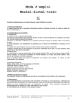
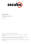
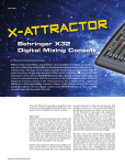
User Manual
G-LEC Solaris+ User Manual
To avoid danger, you should read this user manual thoroughly before use of the product
This product is for professional use only and not designed for home or residential use.
G-LEC Solaris+
Product Information Overview
Solaris +, hanging 360 ° LED video curtain for Events and Installations
Dear Customer, We thank you for purchasing the Solaris+ system from G-LEC. With this
product, you have an efficient and flexible LED video playback system, which has been built
using leading edge technology and components. Before your product left our facility, it was
tested to ensure that you receive a product in perfect condition.
Please ensure that anyone working with the system fully reads and understands this manual
before working with the product and follow its instructions, especially safety related issues.
This manual also contains important information in regard to commissioning. Be sure that this
documentation is forwarded when the product is passed on to third parties. These instructions
should be read are retained.
Should you believe that your product was damaged in transit, please file a report with the
forwarder immediately, otherwise any claim for compensation may be void.
G-LEC Vision GmbH may make improvements and / or changes to the product (s) and / or the
program(s) in this manual without prior notice. The manual could include technical
inaccuracies or typographical errors. Changes and updates are made to this manual
periodically, so to ensure that you have the latest version, please check our website at
www.g-lec.com
Copyright Notice
This manual is the intellectual property of G-LEC Vision GmbH © 2012.
No part of this publication may be reproduced or copied in any way, and by any means and
manner without the express written consent of G-LEC Vision GmbH.
Solaris+ User Manual V1.0
www.G-LEC.com
Tel: +49 (0) 7248 927400
System Components
This chapter describes the typical components and the accessories which the Solaris+ uses in
detail. For other common system components such as media servers, the S-Drive II video
processor and control software, please refer to the relevant user guides.
Solaris+ system components overview:
- S-Drive II Video Processor
This video processor receives an external DVI-D source to be played on a Solaris+
system. It is configured using some free of charge proprietary G-LEC software. A fibre
optic output is sent to the Solaris+ Manager.
- Solaris+ Lines
Available in various standard lengths, Solaris+ Lines are cables mounted with LED
spheres at a pitch of 120mm. Lines can be interconnected in different lengths, up to a
maximum of 64 spheres.
Solaris+ User Manual V1.0
www.G-LEC.com
Tel: +49 (0) 7248 927400
- Solaris+ Bracket
The Solaris+ Bracket is where the Solaris+ Lines plug into. Each bracket has a power
input (from the PSU), a data input (from the Solaris+ Manager) along with 4 outputs for
Solaris+ Lines. It can be mounted by attaching a coupler to the central hole or via the
two M10 threaded sockets at the ends of the Bracket.
- Solaris+ Power Supply Unit (PSU)
The Solaris PSU receives a mains voltage signal and has 8 outputs, each of which
connects to a Solaris Bracket.
Solaris+ User Manual V1.0
www.G-LEC.com
Tel: +49 (0) 7248 927400
- Solaris + Manager
The Solaris+ Manager receives a fibre optic signal from the S-Drive II, and has a fibre
optic output to connect further Managers. It is powered from a mains voltage input and
has 16 CAT-5 outputs, which feed signal to the Solaris+ Brackets.
- G-LEC Software
Available for free download from www.g-lec.com
Solaris+ User Manual V1.0
www.G-LEC.com
Tel: +49 (0) 7248 927400
Solaris+ System Diagram
The Solaris+ system should be connected, as shown in the diagram below.
In order to fully mount a system, please do as follows:
1) Mount the Solaris+ Brackets in their desired location
2) It is recommended to place the Solaris+ PSU and Solaris+ Manager close to the Brackets
in order to minimize cable distances and the potential for problems arising.
3) Connect each bracket to the output from the Solaris+ PSU – there are 8 outputs on each
PSU. The connection is made through a cable with a Neutrik Speakon connector on each
end. These connectors are keyed to only connect one way. There is no specific sequence
in regard to connecting the Solaris+ Bracket to the output of the PSU, but care must be
paid to ensure that any maximum load is not exceeded, as follow:
Note that the top 4 outputs have a maximum capacity of 320 Watts and the bottom 4
outputs have a capacity of a further 320 Watts. Exceeding these ratings is not permitted.
In order to help you calculate the load; each Solaris sphere has a maximum current draw
of 0.5 Watts.
Solaris+ User Manual V1.0
www.G-LEC.com
Tel: +49 (0) 7248 927400
4) The Solaris+ Manager contains 16 numbered outputs. Connect the first output to the
first Solaris+ Bracket in line. This will be fed the first pixel information from the mapping
in the S-Drive II Video Processor. This connection is made using a shielded CAT-5 cable.
Connect output to the second Bracket in line, continuing until the maximum of 16
outputs are used. If you wish to connect further brackets, then a second Solaris+
Manager will be required.
5) Using a compatible fibre optic cable, connect the output of the S-Drive II to the input of
the Solaris+ Manager on the right hand side of the unit. These connectors are keyed, so
need to be inserted the correct way around, but they simply push in to lock. To remove
them, pull gently on the side of the connector only, and it should release. The S-Drive II
will normally sit at your video control position and therefore the use of fibre optic cable
allows the fast transmission of data across longer distances.
6) Should you need to connect further Solaris+ Manager boxes, they can be daisy chained
using further fibre optic cables, connecting the output of the first, to the input of the
next, and so on.
7) Connect your desired configuration of Solaris+ Lines to the Solaris+ Brackets. The
connection between these two elements is via a keyed 4 pin connector. Ensure that
both connector components are correctly aligned and push them together. The male
side of the connector has a locking ring which needs to be turned a quarter turn
clockwise until you feel it physically ‘click’ into place and will not turn further. Once
‘clicked’ a firm connection has been made. To undo these connectors, turn the locking
ring anti-clockwise a quarter turn before attempting to pull the connector apart.
Sequential Solaris+ Lines can be connected using the same method.
8) Each Solaris+ Line has a tab at the first and last sphere. These are for the specific
purpose of attaching a secondary safety wire, and must be used at the point where a
Solaris+ Line connects to a Solaris+ Bracket. Further safety cables should be used where
systems are placed above people or objects which may be damaged.
9) Connect mains power to the Solaris+ Manager, PSU and S-Drive II units via their power
inputs. Turn on all units via their onboard switch.
10) Connect a DVI-D source to the input of the S-Drive II and configure the S-Drive II for your
desired layout. For further information, consult the S-Drive II user manual.
Once configured, your Solaris+ system will play back the signal being fed and distributed via the
S-Drive II.
Solaris+ User Manual V1.0
www.G-LEC.com
Tel: +49 (0) 7248 927400
Maintenance
Cleaning the Fibre Optic Cables and Connectors
In order to clean the fibre optic cables or connections on the S-Drive II and Solaris+ Managers
you should use a soft cloth or swab.
To clean fiber optic cables:
- Place the soft cloth on a flat table
- Carefully remove the optical fiber head by hand
- Gently move the optical fiber several times on the clean cloth to remove any dirt.
To clean fiber optic connectors:
- Insert the swab into each optical opening
- Gently rotate the swab several times and pull it out to remove any dirt.
To clean Solaris+ Spheres and Lines:
To clean the Solaris lines and spheres, you should use a slightly damp cloth. No solvents,
detergents or abrasives should be used, or they will damage the spheres and associated wiring.
Solaris+ User Manual V1.0
www.G-LEC.com
Tel: +49 (0) 7248 927400
Troubleshooting
Please read the following FAQ’s, should you have problems with your system. For further
contact information, please see the ‘Contacts’ section at the end of this manual.
Problem
The green light in the power switch of my Solaris+ PSU / Manager / S-Drive II does not light up
Possible solutions
It is not receiving mains power. Check that the power source is on and that connections are
firmly made. The Neutrik Powercon connector needs to be inserted and turned clockwise to
lock into place and make a connection.
Check the fuses on the units and replace if blown.
Problem
The video signal is playing, but the output from each Bracket is backwards
Possible solutions
The brackets are plugged into the Solaris+ Manager in the wrong order. Try connecting them in
the opposite order if this problem is repeated across all of your brackets
Problem
The video signal is playing backwards on one of my Brackets
Possible solutions
Ensure that the Bracket is physically placed in the same orientation as your other brackets. A
painted arrow on the topside of each bracket can help ensure consistency easily.
Solaris+ User Manual V1.0
www.G-LEC.com
Tel: +49 (0) 7248 927400
Solaris+ Product and Accessories List
Item number
G933004
G933005
G933006
G933007
G933019
G933012
Product Name
Solaris+ Line
Solaris+ Manager
Solaris+ Bracket
Solaris+ PSU
Solaris+ Single
S-Drive II
Description
8 balls on line 96 cm with 12 cm pitch
feeds up to 16 Solaris+ Brackets
Output for 4 Solaris+ Lines
for up to 120 lines
One ball on 12 cm line
Video processor for Solaris+ with DVI-D input
G944013
G944015
G944004
G944005
G944006
G944042
G944022
Fiber Optic Cable 20m
Fibre Optic Coupler metal
CAT-5 Ethernet Cable 2m
CAT-5 Ethernet Cable 5m
CAT-5 Ethernet Cable 10m
Speakon Cable 2.5m
Speakon Cable 5m
G944007
G944008
Blank line extension cable 0.96m
Blank line extension cable 1.92 m
G955009
G955014
G955010
Flight case for Solaris+ Containers (11 containers per case)
Containers for Solaris+ lines (12 Lines per container)
Transflex flight case for accessories
Solaris+ User Manual V1.0
www.G-LEC.com
Tel: +49 (0) 7248 927400
Technical Specifications
Weight
Solaris+ Line - 960mm / 37.8 inches (8 pixels) = 360 grams / 0.8 lbs.
Weight m² - 2.9kg/m² (120mm / 4.7 inch pixel pitch -> 8 single lines -> 64 pixels)
Solaris+ Manager - 4kg / 8.8 lbs.
Solaris+ PSU - 6kg / 13.2 lbs.
Solaris+ Bracket - 620g / 1.4 lbs.
Dimensions
Solaris+ Line length - 960mm / 37.8 inches
Solaris+ Manager - 230 x 430 x 88mm / 9 x 17 x 3.5 inches, 19"/ 2U high
Solaris+ PSU - 300 x 430 x 88mm / 12 x 17 x 3.5 inches, 19 "/ 2U
Solaris+ Bracket - 500 x 50 x 40mm / 20 x 2 x 1.5 inches
Optical
Pixel Pitch - 120mm / 4.7 inches
Pixel - 2 x 3-color SMD LED
Pixel density 64 pixels / m² (Where pixels are set at 120 x 120mm grid)
Colors - 16 million, 24/48bit full color
Electrical
Power - 0.5 Watts / Pixel (at 100% full bright white)
Manager - Data output for 16 Brackets
Solaris+ PSU
Input voltage - 110-240V AC 50/60Hz
Output power 640 Watts max.
Solaris+ Bracket
Power – 130 Watts max. (4 x 8 lines)
Data output - 4 x 8 Lines
Video Source
DVI-D via S-Drive II
Solaris+ User Manual V1.0
www.G-LEC.com
Tel: +49 (0) 7248 927400