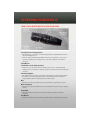
1
2010
IMPORTANT: This User Guide is intended to
familiarize you with the important features of
your vehicle. The DVD enclosed contains your
Owner’s Manual, Navigation/Media Center
Manuals, Warranty Booklets, Tire Warranty and
24-Hour Towing Assistance (new vehicles
purchased in the U.S.) or Roadside Assistance
(new vehicles purchased in Canada) in electronic
format. We hope you find it useful. If you are the
first registered owner of your vehicle, you may
obtain a printed copy of the Owner’s Manual,
Navigation/Media Center Manuals or Warranty
Booklet by calling 1-800-423-6343 (U.S.) or
1-800-387-1143 (Canada) or by contacting your
dealer. Replacement DVD kits may be purchased
by visiting www.techauthority.com.
Copyright © 2010 Chrysler Group LLC.
TABLE OF CONTENTS
INTRODUCTION/WELCOME
DRIVER COCKPIT . . . . . . . . . . . . . . 4
INSTRUMENT CLUSTER . . . . . . . . . . 6
UNIVERSAL GARAGE DOOR OPENER
(HOMELINK®) . . . . . . . . . . . .
POWER INVERTER . . . . . . . . . .
POWER OUTLETS . . . . . . . . . . .
Uconnect™ Phone . . . . . . . . . .
VOICE COMMAND . . . . . . . . . .
GETTING STARTED
UTILITY
WELCOME FROM CHRYSLER GROUP LLC . . 2
CONTROLS AT A GLANCE
KEY FOB . . . . . . . . . . . .
THEFT ALARM . . . . . . . . .
SEAT BELT . . . . . . . . . .
CHILD RESTRAINTS . . . . . .
FRONT SEATS . . . . . . . . .
HEATED SEATS . . . . . . . .
TILT STEERING COLUMN . . .
ADJUSTABLE PEDALS . . . .
PROGRAMMABLE FEATURES
.
.
.
.
.
.
.
.
.
.
.
.
.
.
.
.
.
.
.
.
.
.
.
.
.
.
.
.
.
.
.
.
.
.
.
.
.
.
.
.
.
.
.
.
.
.
.
.
.
.
.
.
.
.
. 8
. 9
. 9
.10
. 13
. 15
. 17
. 17
.18
OPERATING YOUR VEHICLE
TURN SIGNAL/WIPER/WASHER/HIGH
BEAM LEVER . . . . . . . . . . . . . .
HEADLIGHT SWITCH AND HALO LIGHT
SWITCH . . . . . . . . . . . . . . . . .
SPEED CONTROL LEVER . . . . . . . .
ELECTRONIC RANGE SELECTION (ERS) .
MANUAL CLIMATE CONTROLS . . . . .
FRONT THREE ZONE MANUAL CLIMATE
CONTROLS . . . . . . . . . . . . . . .
FRONT THREE ZONE AUTOMATIC
TEMPERATURE CONTROLS (ATC) . . .
PARKSENSE® REAR PARK ASSIST . . .
PARKVIEW® REAR BACK-UP CAMERA .
REAR CROSS PATH WITH BLIND SPOT
MONITORING . . . . . . . . . . . . . .
POWER SLIDING SIDE DOORS . . . . .
STOW 'N GO® SEATING . . . . . . . .
SWIVEL N’ GO™ SEATING WITH TABLE
THIRD ROW POWER RECLINER . . . . .
POWER LIFTGATE . . . . . . . . . . . .
POWER SUNROOF . . . . . . . . . . .
WIND BUFFETING . . . . . . . . . . . .
. 20
.
.
.
.
. 21
22
.23
.23
IN-FLOOR STORAGE – STOW N’ GO® .
TRAILER TOWING WEIGHTS (MAXIMUM
TRAILER WEIGHT RATINGS) . . . . . .
RECREATIONAL TOWING (BEHIND
MOTORHOME, ETC.) . . . . . . . . . .
BRAKE/TRANSMISSION INTERLOCK
MANUAL OVERRIDE . . . . . . . . . .
.
.
.
.
.
.43
.45
.45
46
48
. 49
. .50
. . 51
. . 51
WHAT TO DO IN EMERGENCIES
24-HOUR TOWING ASSISTANCE U.S. ONLY . . . . . . . . . . . .
INSTRUMENT CLUSTER WARNING
LIGHTS . . . . . . . . . . . . . .
IF YOUR ENGINE OVERHEATS . .
JACKING AND TIRE CHANGING . .
JUMP-STARTING . . . . . . . . .
TOWING A DISABLED VEHICLE . .
FREEING A STUCK VEHICLE . . .
EVENT DATA RECORDER (EDR) .
. . . . .52
.
.
.
.
.
.
.
.
.
.
.
.
.
.
.
.
.
.
.
.
.
.
.
.
.
.
.
.
.52
.55
.56
.61
64
.65
.65
.
.
.
.
.
.
.
.
.
.
.
.
.
.
.
.
.
.
.
.
.
.
.
.
.
.
.
.
.
.
.
.
.
.
.
.
.67
.67
69
. 71
.72
.74
.77
.78
.78
MAINTAINING YOUR VEHICLE
. 24
. .25
. .27
. .27
.
.
.
.
.
.
.
.
28
28
29
30
. 31
.32
.32
.33
ELECTRONICS
NON-TOUCH-SCREEN RADIOS . . . .
TOUCH-SCREEN RADIOS . . . . . . .
REMOTE AUDIO CONTROLS . . . . .
VIDEO ENTERTAINMENT
SYSTEM (VES)™ . . . . . . . . . . .
UNIVERSAL CONSUMER INTERFACE .
ELECTRONIC VEHICLE INFORMATION
CENTER (EVIC) . . . . . . . . . . . .
.
.
.
.
.
. . .34
. . 36
. . 40
. . 40
. . 42
OPENING THE HOOD . . . . . .
ADDING FUEL . . . . . . . . . .
ENGINE COMPARTMENT . . . .
FLUIDS AND CAPACITIES . . . .
MAINTENANCE CHART . . . . .
FUSES . . . . . . . . . . . . . .
TIRE PRESSURES . . . . . . . .
WHEEL AND WHEEL TRIM CARE
EXTERIOR BULBS . . . . . . . .
.
.
.
.
.
.
.
.
.
CONSUMER ASSISTANCE
CHRYSLER GROUP LLC CUSTOMER
CENTER . . . . . . . . . . . . . . . .
CHRYSLER CANADA INC. CUSTOMER
CENTER . . . . . . . . . . . . . . . .
ASSISTANCE FOR THE HEARING
IMPAIRED . . . . . . . . . . . . . . .
PUBLICATIONS ORDERING . . . . . .
REPORTING SAFETY DEFECTS IN
THE 50 UNITED STATES AND
WASHINGTON, D.C. . . . . . . . . .
TIRE WARRANTY . . . . . . . . . . .
. . .79
. . .79
. . .79
. . .79
. . 80
. . 80
MOPAR ACCESSORIES
. . .43
MOPAR® ACCESSORIES . . . . . . . . . .83
INTRODUCTION/WELCOME
WELCOME FROM CHRYSLER GROUP LLC
Congratulations on selecting your new Chrysler Group LLC vehicle. Be assured that it
represents precision workmanship, distinctive styling, and high quality - all essentials
that are traditional to our vehicles.
This guide illustrates and describes the operation of features and equipment that are
either standard or optional on this vehicle. This guide may also include a description of
features and equipment that are no longer available or were not ordered on this vehicle.
Please disregard any features and equipment described in this guide that are not
available on this vehicle. Chrysler Group LLC reserves the right to make changes in
design and specifications and/or make additions to or improvements to its products
without imposing any obligation upon itself to install them on products previously
manufactured.
For complete owner information, refer to the DVD in the owner’s kit provided at the time
of new vehicle purchase. For your convenience, the information contained on the DVD
may also be printed and saved for future reference.
Chrysler Group LLC is committed to protecting our environment and natural resources. By
converting from paper to electronic delivery for the majority of the user information for
your vehicle, together we greatly reduce the demand for tree-based products and lessen
the stress on our environment.
Vehicles Sold In Canada
With respect to any Vehicles sold in Canada, the name Chrysler Group LLC shall be
deemed to be deleted and the name Chrysler Canada Inc. used in substitution therefore.
Driving And Alcohol
Drunken driving is one of the most frequent causes of accidents.
Your driving ability can be seriously impaired with blood alcohol levels far below the
legal minimum. If you are drinking, don’t drive. Ride with a designated non-drinking
driver, call a cab, a friend, or use public transportation.
WARNING!
Driving after drinking can lead to an accident. Your perceptions are less sharp, your
reflexes are slower, and your judgment is impaired when you have been drinking.
Never drink and then drive.
2
INTRODUCTION/WELCOME
CAUTION!
Never park your vehicle over dry grass or other combustible materials. The heat from
your vehicle exhaust system could cause a fire.
CHRYSLER, DODGE, JEEP, ATF+4, MOPAR and Uconnect are registered trademarks of
Chrysler Group LLC.
COPYRIGHT ©2010 CHRYSLER GROUP LLC
3
CONTROLS AT A GLANCE
DRIVER COCKPIT
4
CONTROLS AT A GLANCE
5
CONTROLS AT A GLANCE
INSTRUMENT CLUSTER
Warning Lights
- Low Fuel Warning Light
- Charging System Light**
- Oil Pressure Warning Light**
- Anti-Lock Brake (ABS) Light**
- Airbag Warning Light**
- Electronic Throttle Control (ETC) Light
- Tire Pressure Monitoring System (TPMS) Light
- Engine Temperature Warning Light
- Seat Belt Reminder Light
BRAKE
- Brake Warning Light**
- Malfunction Indicator Light (MIL)**
- Electronic Stability Program (ESP) Indicator Light/Brake Assist System
(BAS) Warning Light**
6
CONTROLS AT A GLANCE
Indicators
- Turn Signal Indicators
- High Beam Indicator
- Front Fog Light Indicator
- Vehicle Security Indicator*
- Electronic Stability Program (ESP)/Traction Control System (TCS)
Indicator
Odometer Messages
ECO - Fuel Saver Indicator
ECO-ON - Fuel Saver Indicator On
door - Door Ajar
gATE* - Liftgate Ajar
hood - Hood Ajar
gASCAP - Fuel Cap Fault
LoWASH - Low Washer Fluid
noFUSE* - Fuse Fault
LoW tirE* - Low Tire Pressure
LoCOOL - Low Coolant
CHAngE OIL* - Change Engine Oil
CRUISE - Cruise Control On
* If equipped
** Bulb Check with Key On
7
GETTING STARTED
KEY FOB
Locking And Unlocking The
Doors/Liftgate
• Press the LOCK button once to lock all the
doors and the liftgate. Press the UNLOCK
button once to unlock the driver’s door only
and twice within five seconds to unlock all
the doors and liftgate.
• All doors can be programmed to unlock on
the first press of the UNLOCK button. Refer
to Programmable Features in this guide.
WARNING!
Leaving unattended children in a vehicle is dangerous for a number of reasons. A child
or others could be severely injured or killed. Children should be warned not to touch
the parking brake, brake pedal, or the shift lever. Do not leave the Key Fob in the
ignition. A child could operate power windows, other controls, or move the vehicle.
Remote Start
• Press the REMOTE START button 2 twice within five seconds. Pressing the REMOTE
START button a third time shuts the engine off.
x
• To drive the vehicle, press the UNLOCK button, insert the Key Fob in the ignition and
turn to the ON/RUN position.
• With remote start, the engine will only run for 15 minutes (timeout) unless the ignition
Key Fob is placed in the ON/RUN position.
• The vehicle must be started with the Key Fob after two consecutive timeouts.
WARNING!
• Do not start or run an engine in a closed garage or confined area. Exhaust gas
contains Carbon Monoxide (CO) which is odorless and colorless. Carbon Monoxide
is poisonous and can cause serious injury or death when inhaled.
• Keep Key Fob transmitters away from children. Operation of the Remote Start
System, windows, door locks or other controls could cause serious injury or death.
8
GETTING STARTED
Panic Alarm
• Press the PANIC button once to turn the panic alarm on.
• Wait approximately three seconds and press the button a second time to turn the
panic alarm off.
Power Liftgate
• Press the LIFTGATE button twice within five seconds to power open/close the Power
Liftgate. If the button is pressed while the liftgate is being power closed, the liftgate
will reverse to the full open position.
Power Sliding Doors
• Press the LEFT or RIGHT Power Sliding Door button twice within five seconds to power
open/close the Power Sliding Door. If the button is pressed while the door is being
power closed, the door will reverse to the full open position.
Express Window Feature
• To remotely lower both front door windows at the same time, press and release the
UNLOCK button and then immediately press and hold the UNLOCK button until the
windows lower to the level desired or until they lower completely.
Emergency Key
• Should the battery in the vehicle or the Key Fob transmitter go dead, there is an
emergency key located in the Key Fob. To remove the emergency key, slide the button
at the top of the Key Fob sideways with your thumb and then pull the key out with your
other hand.
• The emergency key is also for locking the lower glove compartment.
THEFT ALARM
To Arm
• Press the Key Fob LOCK button or the power door lock switch while the door is open.
To Disarm
• Press the Key Fob UNLOCK button and turn the ignition to the ON/RUN position.
SEAT BELT
• Be sure everyone in your vehicle is in a seat and using a seat belt properly.
WARNING!
In a collision, you and your passengers can suffer much greater injuries if you are not
properly buckled up. You can strike the interior of your vehicle or other passengers, or
you can be thrown out of the vehicle. Always be sure you and others in your vehicle
are buckled up properly.
9
GETTING STARTED
CHILD RESTRAINTS
• Children 12 years and under should ride properly buckled up in a rear seat, if
available. According to crash statistics, children are safer when properly restrained in
the rear seats rather than in the front.
• Every state in the United States and all Canadian provinces require that small children
ride in proper restraint systems. This is the law, and you can be prosecuted for
ignoring it.
WARNING!
In a collision, an unrestrained child, even a tiny baby, can become a projectile inside
the vehicle. The force required to hold even an infant on your lap could become so
great that you could not hold the child, no matter how strong you are. The child and
others could be severely injured or killed. Any child riding in your vehicle should be in
a proper restraint for the child's size.
Integrated Child Booster Seat
• The Integrated Child Booster Seat, located in each second-row passenger seat, is
designed for children weighing between 48 and 85 lbs (22 and 39 kg) and between
47 in (119 cm) and 57 in (145 cm) tall.
• To position a child into the Integrated Child Booster Seat follow these steps:
• Pull the release handle, located at the front of the seat cushion, forward to release.
Then, lift seat cushion up and push back to lock it in the booster seat position.
WARNING!
Failure to comply with the following conditions could result in serious injury or death:
• The swivel seat should be locked in the forward-facing position when using the
booster seat with the vehicle in motion.
• Be certain that the seat cushion is locked securely into position before using the
seat. An improperly latched seat cushion could cause serious injury.
• Place the child upright in the seat with their back firmly against the seatback.
• Grasp the latch plate and pull out the seat belt.
• Slide the latch plate up the webbing as far as necessary to allow the seat belt to go
around the child’s lap.
NOTE: The lap portion of the seat belt should be low on the hips and as snug as
possible.
• Once the seat belt is long enough to fit properly, insert the latch plate into the buckle
until you hear a “click.”
• To remove the slack from the lap belt, pull upward on the shoulder portion of the seat
belt and release by pushing the red button on the buckle.
10
GETTING STARTED
Installing The LATCH - Compatible Child Restraint System
• Each vehicle, except commercial cargo vehicles, is equipped with the child restraint
anchorage system called LATCH, which stands for Lower Anchors and Tether for
CHildren.
• Two LATCH child restraint anchorage systems are installed on all second-row seats and
in the center position on all third row fold-in-floor seats.
• Second-row seats also feature tether strap anchorages, located in the rear surface of
the seatback.
• In addition, all third row fold-in-floor seats are equipped with a child restraint tether
anchor at the center seating position.
Installing The Lower Attachments:
• The vehicle lower anchorages are round bars located at the rear of the seat cushion
where it meets the seatback.
• Loosen the adjusters on the lower child
restraint attachment straps to ease the
installation.
NOTE: It is recommended to loosen the top
tether strap and route it loosely prior to
securing the lower anchors so the top tether
strap is not trapped between the vehicle seat
and child restraint.
• Attach the lower child restraint attachment straps to the vehicle’s lower anchor bars.
Ensure that the lower attachment strap is firmly engaged and that the hook is secure.
• Tighten the lower attachment strap while firmly pushing the child restraint rearward
and downward into the vehicle seat. Remove all slack in the lower attachment straps.
11
GETTING STARTED
Installing The Top Tether Strap (With Either Lower Anchors Or Vehicle Seat
Belt):
• Route the top tether strap under the adjustable head restraint between the steel
posts.
• Provide enough slack for the tether strap to
reach the tether anchor located near the
bottom of the seat back.
• Clip tether hook to tether anchor. Ensure
that the hook is firmly engaged and secure.
• Remove all slack and tighten tether strap
according to child restraint manufacturer’s
instructions.
NOTE: The top tether strap is always to be
secured, regardless of if the child restraint is
installed with the lower anchors or the vehicle
seat belt.
WARNING!
Never place any child seat, booster seat, or infant carrier in the Swivel 'n Go seat while
it is in the rearward-facing position. The swivel seat should be locked in the forward
position when using any child seat, booster seat, or infant carriers, with the vehicle in
motion. Failure to do so could result in serious injury or even death.
WARNING!
An incorrectly anchored tether strap could lead to increased head motion and
possible injury to the child. Use only the anchor positions directly behind the child
seat to secure a child restraint top tether strap.
12
GETTING STARTED
Installing The Child Restraint Using The Vehicle Seat Belts
• To install a child restraint, first, pull enough of the seat belt webbing from the retractor
to route it through the belt path of the child restraint and slide the latch plate into the
buckle.
• Next, extract all the seat belt webbing out of the retractor and then allow the belt to
retract into the retractor. Finally, pull on any excess webbing to tighten the lap portion
around the child restraint. Any seat belt system will loosen with time, so check the
belt occasionally, and pull it tight if necessary.
• Once you have completed securing the child restraint with the seat belt, secure the
top tether strap.
WARNING!
Rearward-facing child seats must NEVER be used in the front seat of a vehicle with a
front passenger airbag. An airbag deployment could cause severe injury or death to
infants in this position.
FRONT SEATS
WARNING!
Adjusting a seat while the vehicle is moving is dangerous. The sudden movement of
the seat could cause you to lose control. The seat belt might not be properly adjusted,
and you could be severely injured or killed. Only adjust a seat while the vehicle is
parked.
Manual Seat Adjustment
Forward/Rearward
• Lift up on the adjusting bar located at the
front of the seat near the floor and release
at the desired position.
13
GETTING STARTED
Recliner
• Lift the recliner lever located on the
outboard side of the seat, lean back and
release at the desired position.
WARNING!
Do not ride with the seatback reclined so that the seat belt is no longer resting against
your chest. In a collision, you could slide under the seat belt and be severely injured
or killed. Use the recliner only when the vehicle is parked.
Manual Lumbar Adjust Lever
• Rotate the lumbar adjust lever downward to
increase the support or upward to decrease
the support.
Eight-Way Driver And Passenger Power Seat
• The recline switch, located on the outboard
side of the seat, controls seatback
adjustment.
• The power seat switch controls
forward/back, up/down, and tilt
adjustment.
14
GETTING STARTED
CAUTION!
DO NOT place any article under a power seat or impede its ability to move as it may
cause damage to the seat controls. Seat travel may become limited if movement is
stopped by an obstruction in the seat's path.
Memory Seats
• The memory seat feature allows you to save
two different driver seating positions,
driver's outside mirror, adjustable brake
and accelerator pedals, and radio station
preset settings. The memory seat buttons
are located on the driver's door panel.
• Adjust all memory profile settings, press the
SET button then press 1 or 2 within five
seconds.
• To program a Key Fob to the memory position, press and release the LOCK button
within 10 seconds on the Key Fob to be programmed.
• Place the ignition switch in the ON position, select Remote Linked to Memory in the
Electronic Vehicle Information Center (EVIC) and enter Yes.
• Press 1 or 2 to recall the saved positions, or press UNLOCK on the programmed Key
Fob.
HEATED SEATS
Front Heated Seats
• The controls for front heated seats are
located on the center instrument panel
area.
• Press the switch once to select High-level
heating. Press the switch a second time to
select Low-level heating. Press the switch a
third time to shut the heating elements Off.
15
GETTING STARTED
Second Row Heated Seats
• Second row heated seat switches are
located in the sliding door handle trim
panels.
• Press the switch once to select High-level
heating. Press the switch a second time to
select Low-level heating. Press the switch a
third time to shut the heating elements Off.
WARNING!
• Persons who are unable to feel pain to the skin because of advanced age, chronic
illness, diabetes, spinal cord injury, medication, alcohol use, exhaustion or other
physical conditions must exercise care when using the seat heater. It may cause
burns even at low temperatures, especially if used for long periods of time.
• Do not place anything on the seat that insulates against heat, such as a blanket or
cushion. This may cause the seat heater to overheat. Sitting in a seat that has been
overheated could cause serious burns due to the increased surface temperature of
the seat.
CAUTION!
Repeated overheating of the seat could damage the heating element and/or degrade
the material of the seat.
16
GETTING STARTED
TILT STEERING COLUMN
• The tilt steering column tilt lever is located
below the steering wheel.
• Push down on the tilt lever to unlock the
steering column.
• With one hand firmly on the steering wheel,
move the steering column upward or
downward as desired.
• Pull upward on the tilt lever to lock the
column firmly in place.
WARNING!
Do not adjust the steering wheel while driving. The tilt adjustment must be locked
while driving. Adjusting the steering wheel while driving or driving without the tilt
adjustment locked could cause the driver to lose control of the vehicle. Failure to
follow this warning may result in severe injury or death.
ADJUSTABLE PEDALS
• Press the switch located on the left side of
the steering column forward to move the
brake and accelerator pedals away from the
driver and press the switch rearward to
move the pedals closer to the driver.
NOTE: The pedals cannot be adjusted when
the vehicle is in REVERSE or when the
Electronic Speed Control is set.
WARNING!
Do not adjust the pedals while the vehicle is moving. You could lose control and have
an accident. Always adjust the pedals while the vehicle is parked.
17
GETTING STARTED
CAUTION!
Do not place any article under the adjustable pedals or impede its ability to move, as
it may cause damage to the pedal controls. Pedal travel may become limited if
movement is stopped by an obstruction in the adjustable pedal's path.
PROGRAMMABLE FEATURES
Electronic Vehicle Information Center (EVIC) – If Equipped
• The EVIC can be used to program the following Personal Settings. Press and release
until Personal Settings displays, then press the STEP
the MENU button
button
to scroll through the settings. Press the RESET button to change the
setting.
• Language
• Auto Door Locks
• Auto UNLK On Exit
• RKE Unlock
• RKE Linked To Memory
• Flash Lamp Lock
• Headlamp Off Delay
• Easy Exit Seat
• Tilt MIRR. In Reverse
• Turn Headlamps On With Remote Key
Unlock
• Rain Sensing Intermittent Wipers
• Key-Off Power Delay
• ILLUMIN. Approach
• Blind Spot Alert
• Park ASST. System
• Display Units of Measure In
• Door Alert
• Automatic High Beams
• Display ECO
• Sound Horn With Remote Key Lock
Key Fob Programmable Features
• The following features may also be programmed by using the Key Fob transmitter or
the ignition switch and driver's door lock switch.
NOTE: Pressing the LOCK button while you are inside the vehicle will activate the
Vehicle Security Alarm. Opening a door with the Vehicle Security Alarm activated will
cause the alarm to sound. Press the UNLOCK button to deactivate the Vehicle Security
Alarm.
Unlock On First Press
• To unlock either the driver's side, or all doors, on the first press of the UNLOCK button:
• Press and hold the LOCK button for at least 4 seconds, but no longer than
10 seconds. Then, press and hold the UNLOCK button while still holding the LOCK
button.
• Release both buttons at the same time.
18
GETTING STARTED
Auto Unlock Doors On Exit
• To have all of the vehicle doors unlock when any door is opened:
• Enter your vehicle, close all the doors and fasten your seat belt.
• Within 15 seconds, cycle the ignition switch from the LOCK position to the ON/RUN
position a minimum of five times ending in the ON position (do not start the
engine).
• Within 30 seconds, press the driver’s door lock switch in the UNLOCK direction. A
single chime will indicate that programming is complete.
Auto Door Lock
• To have the doors lock automatically when the vehicle’s speed exceeds 15 mph
(24 km/h):
• Enter your vehicle, close all the doors and fasten your seat belt.
• Within 15 seconds, cycle the ignition switch from the LOCK position to the ON/RUN
position a minimum of five times ending in the ON position (do not start the
engine).
• Within 30 seconds, press the driver’s door lock switch in the LOCK direction. A
single chime will indicate that programming is complete.
Sound Horn With Lock
• To turn the horn chirp on or off when the doors are locked:
• Press the LOCK button for at least 4 seconds, but no longer than 10 seconds. Then,
press the PANIC button while still holding the LOCK button.
• Release both buttons at the same time.
Flashing Lights With Lock
• The turn signal lights flashing, when the doors are locked or unlocked, feature can be
turned on or off. To turn this feature on or off:
• Press and hold the UNLOCK button for at least 4 seconds, but no longer than
10 seconds. Then, press and hold the LOCK button while still holding the UNLOCK
button.
• Release both buttons at the same time.
19
OPERATING YOUR VEHICLE
TURN SIGNAL/WIPER/WASHER/HIGH BEAM LEVER
Turn Signal/Lane Change Assist
• Tap the lever up or down once and the turn signal (right or left) will flash three times
and automatically turn off.
• Vehicles equipped with Blind Spot Monitoring may be programmed to add a visual
alert when signaling a lane change; refer to your Owner’s Manual on the DVD for
operation.
Front Wipers
Intermittent, Low And High Operation
• Rotate the end of the lever to the first detent position for one of five intermittent
settings, the second detent for low wiper operation and the third detent for high wiper
operation.
Rain Sensing Wipers
• This feature senses moisture on the vehicle’s windshield and automatically activates
the wipers for the driver when the switch is in the intermittent positions. Refer to
Programmable Features in Getting Started for further details.
Mist
• Push the end of the lever inward to the first detent when a single wipe is desired.
Washer Operation
• Push the end of the lever inward to the second detent and hold for as long as spray is
desired.
Rear Wiper
• Rotate the center portion of the lever forward to the first detent for rear wiper
operation.
Rear Washer
• Rotate the center portion of the lever past the first detent to activate the rear washer.
20
OPERATING YOUR VEHICLE
High Beams
• Push the lever away from you to activate the high beams.
• A high beam symbol will illuminate in the cluster to indicate the high beams are on.
NOTE: For safe driving, turn off high beams when oncoming traffic is present to prevent
headlight glare and as a courtesy to other motorists.
HEADLIGHT SWITCH AND HALO LIGHT SWITCH
Automatic Headlights/Parking
Lights/Headlights
• Rotate the headlight switch, located on the
instrument panel to the left of the steering
wheel, to the first detent for parking
and to the second detent for
lights
headlights
.
• Rotate the headlight switch to “A” for AUTO
headlights.
• When set to “A” (AUTO), the system
automatically turns the headlights on or off
based on ambient light levels.
SmartBeams™
• This system automatically controls the use of the headlight high beams. Refer to
Programmable Features in Getting Started for further details.
Instrument Panel Dimmer
• Rotate the dimmer control to the extreme bottom position to fully dim the instrument
panel lights and prevent the interior lights from illuminating when a door is opened.
• Rotate the dimmer control up to increase the brightness of the instrument panel when
the parking lights or headlights are on.
• Rotate the dimmer control up to the next detent position to fully brighten the
odometer and radio when the parking lights or headlights are on. Refer to your Media
Center/Radio User Manual on the DVD for display dimming.
• Rotate the dimmer control up to the last detent position to turn on the interior lighting.
Overhead (Halo) Light
• Halo lights are strategically placed soft lighting that help illuminate specific areas
while driving at night.
• Push the button to turn ON/OFF the overhead (halo) lighting.
21
OPERATING YOUR VEHICLE
SPEED CONTROL LEVER
Cruise ON/OFF
• Push the ON/OFF button to activate the
Speed Control.
• CRUISE will appear on the instrument
cluster to indicate the Speed Control is on.
• Push the ON/OFF button a second time to
turn the system off.
WARNING!
Leaving the Electronic Speed Control system on when not in use is dangerous. You
could accidentally set the system or cause it to go faster than you want. You could lose
control and have an accident. Always leave the Electronic Speed Control system off
when you are not using it.
Set
• With Speed Control on, push down and release the lever to set a desired speed.
WARNING!
Electronic Speed Control can be dangerous where the system cannot maintain a
constant speed. Your vehicle could go too fast for the conditions, and you could lose
control. An accident could be the result. Do not use Electronic Speed Control in heavy
traffic or on roads that are winding, icy, snow-covered or slippery.
Accel/Decel
• Push and hold the lever up to accelerate or down to decelerate the vehicle; release the
lever to save the new set speed.
• Once a speed is set, tapping the lever up or down will increase or decrease the set
speed approximately 1 mph (2 km/h).
Resume
• To resume a previously selected speed in memory, push the lever up and release.
Cancel
• Pull the lever toward you or apply the brakes to cancel the set speed and maintain the
set speed in memory.
• Push the ON/OFF button to turn the system off and erase the set speed memory.
22
OPERATING YOUR VEHICLE
ELECTRONIC RANGE SELECTION (ERS)
• The Electronic Range Select (ERS) feature
allows you to select the desired top gear.
For example, if you shift the transmission
into third gear, the transmission will never
shift above third gear, but can shift down to
second or first gear automatically when
needed.
• To shift from DRIVE mode to ERS mode,
move the shift lever to the left (-) once. The
current gear will be maintained as the top
gear. To disable ERS, simply press and hold
the shift lever to the right (+) until “D” is
displayed in the instrument cluster
odometer.
• Switching from ERS to DRIVE can be done at
any vehicle speed.
MANUAL CLIMATE CONTROLS
Air Recirculation
• Use recirculation for maximum A/C operation.
• For window defogging, turn the recirculation button off.
• Recirculation is not allowed in defrost, floor, defrost/floor (mix) modes.
23
OPERATING YOUR VEHICLE
FRONT THREE ZONE MANUAL CLIMATE CONTROLS
Air Recirculation
• Use recirculation for maximum A/C operation.
• For window defogging, turn the recirculation button off.
• Recirculation is not allowed in defrost, floor, defrost/floor (mix) modes.
Rear Window Defroster
• Pressing the rear window defroster button will turn on the defroster for approximately
10 minutes. An indicator in the button will illuminate when the rear window defroster
is on. For an additional five minutes of operation, press the button a second time.
24
OPERATING YOUR VEHICLE
Activating Rear Passenger Climate Controls
• Rotate the rear blower control, located on the main climate control in the instrument
panel, to the “RR” position. This enables the rear passenger climate controls located
in the headliner above the second row seats.
FRONT THREE ZONE AUTOMATIC TEMPERATURE CONTROLS
(ATC)
Automatic Operation
• Push the AUTO mode button to activate the ATC system.
• Select the desired temperature by rotating the temperature controls for the driver or
passenger.
• The system will maintain the set temperature automatically.
25
OPERATING YOUR VEHICLE
Air Conditioning (A/C)
• If the A/C button is pushed while in AUTO mode, the indicator light may flash three
times to indicate the air conditioning is being controlled automatically.
SYNC Temperature Button
• Push the SYNC button once to control driver and passenger temperatures
simultaneously. Push the SYNC button a second time to control the temperatures
individually.
Air Recirculation
• Use recirculation for maximum A/C operation.
• For window defogging, turn the recirculation button off.
• If the recirculation button is pushed while in the AUTO mode, the indicator light may
flash three times to indicate the cabin air is being controlled automatically.
Rear Window Defroster
• Pressing the rear window defroster button will turn on the defroster for approximately
10 minutes. An indicator in the button will illuminate when the rear window defroster
is on. For an additional five minutes of operation, press the button a second time.
26
OPERATING YOUR VEHICLE
Activating Rear Automatic Temperature Control
• Pressing the REAR LOCK button for the Rear ATC System from the front lower ATC panel,
illuminates a LOCK symbol in the rear display. The rear temperature and air source are
controlled from the front lower ATC panel.
• Rear second row occupants can only adjust the rear ATC control when the REAR LOCK
button is turned off.
• The Rear ATC System is located in the headliner, near the center of the vehicle.
PARKSENSE® REAR PARK ASSIST
• If an object is detected behind the rear bumper while the vehicle is in REVERSE, a
warning will display in the instrument cluster and a tone, that changes speed
depending on the distance of the object from the bumper, will sound.
PARKVIEW® REAR BACK-UP CAMERA
• You can see an on-screen image of the rear of your vehicle whenever the shift lever is
put into REVERSE. The ParkView® Rear Back-Up Camera image will be displayed on the
radio display screen, located on the center stack of the instrument panel.
WARNING!
Drivers must be careful when backing up even when using the ParkView® Rear
Back-Up Camera. Always check carefully behind your vehicle, and be sure to check for
pedestrians, animals, other vehicles, obstructions, or blind spots before backing up.
You must continue to pay attention while backing up. Failure to do so can result in
serious injury or death.
27
OPERATING YOUR VEHICLE
REAR CROSS PATH WITH BLIND SPOT MONITORING
• The Blind Spot Monitoring (BSM) system warning light, located in the outside mirrors,
will illuminate if a vehicle moves into a blind spot zone.
• The BSM system can also be configured to sound an audible (chime) alert and mute
the radio to notify you of objects that have entered the detection zones.
• Refer to your owner's manual on the DVD for further details.
POWER SLIDING SIDE DOORS
Automatic/Manual Operation
• The power sliding door may be opened or closed manually or by using the buttons on
the Key Fob, overhead console switch, or rear door switch.
• Pulling the inside or outside power sliding door handle will also power open the
power sliding doors.
Sliding Side Door Child Protection Lock
• When this system is engaged, the inside manual door handle will not open the sliding
door even though the inside door lock is in the unlocked position.
• To engage the Child Protection Door Lock, open the sliding side door. Slide the child
protection door lock control, located on the rear of the sliding door, inward (toward
the vehicle) to engage.
• Repeat these steps on the opposite sliding door.
28
OPERATING YOUR VEHICLE
STOW 'N GO® SEATING
• Move the front seat fully forward. Lower the head restraints and raise the armrests on
the second row seat.
• Slide the storage bin locking mechanism to the "LOCK" position and then pull up on
the storage bin latch to open the cover.
• Pull up on the seatback recliner lever, located on the outboard side of the seat, and
fold the seatback down. To assure the seatback is latched in the folded position,
additional downward pressure on the seatback may be required when folding.
• Pull rearward on the release strap, located at the rear of the seat, and tumble the seat
forward into the storage bin.
• Close the storage bin cover.
29
OPERATING YOUR VEHICLE
SWIVEL N’ GO™ SEATING WITH TABLE
To Swivel The Seats
• Pull the lower handle on the outboard side of the seat and push the side of the seatback
to begin rotation. Once the seat begins to rotate, the handle may be released. The seat
locks in position once reaching the forward or rearward positions only.
Table Installation
• Open the floor storage cover in front of the second row seats.
• Remove the pole and table top by loosening the hook and loop straps.
• Pull the lower handle to swivel the second row seats so they are facing the rear.
• Insert the pole into the base by aligning the lock button into the notch of the base.
• Twist the pole in a clockwise rotation until it stops.
NOTE: You will hear an audible “click” when the lock buttons engage.
• Place the table top over the installed pole aligning with the mating feature of the
underside of the table top. Apply pressure on the table top and press downward.
30
OPERATING YOUR VEHICLE
To Remove The Seats
• Remove any obstructions from the floor behind the seat, and stow the third row seat.
• Pull up on the release bar located at the bottom front edge of the swivel seat.
• From behind the seat, lift up on the rear of the seat cushion while pulling the seat in a
rearward direction.
• Remove the seat from the vehicle through the liftgate. Rollers are part of the seat
frame and will ease the removal process.
• Lower the release handle located at the bottom front edge of the seat.
THIRD ROW POWER RECLINER
• The power recline feature, located on the side of the seat cushion, adjusts the
seatback angle forward/rearward for occupant comfort.
Third Row Power Seat Switch
• A one-touch power folding seat switch is
located in the left rear trim panel as part of a
switch bank.
• Left and right third row seats can be folded
individually or together. The third row power
folding seats adjust to multiple positions.
• The switch is only functional when the
liftgate is open and the vehicle is in PARK.
NOTE:
• Disconnect the center shoulder belt from the small buckle and lower the head
restraints before attempting to fold/stow the power third row seats.
• To abort seat operation while the seat is in motion, press a different seat position
selector switch to stop the seat. Once the seat stops moving, then the desired
position can be selected.
• The third row power seat system includes obstacle detection for safe operation. When
the system detects an obstacle, the motors will stop and reverse the motion a short
distance to move the seat away from the obstacle. Should this occur, remove the
obstacle and press the button again for the desired position.
• Refer to your Owner's Manual on the DVD for manual third row seat folding
instructions.
31
OPERATING YOUR VEHICLE
POWER LIFTGATE
• The power liftgate may be opened and closed by pressing the button on the Key Fob or
the button located on the overhead console. Press the button once to open, and a
second time to close the power liftgate.
• The power liftgate may be closed by the button, located in the upper left trim in the
liftgate opening. Pressing once will only close the liftgate. This button cannot be used
to open the liftgate.
POWER SUNROOF
• The power sunroof switch is located on the overhead console.
WARNING!
• Never leave children in a vehicle with the key in the ignition switch. Occupants,
particularly unattended children, can become entrapped by the power sunroof
while operating the power sunroof switch. Such entrapment may result in serious
injury or death.
• In an accident, there is a greater risk of being thrown from a vehicle with an open
sunroof. You could also be severely injured or killed. Always fasten your seat belt
properly and make sure all passengers are properly secured too.
• Do not allow small children to operate the sunroof. Never allow your fingers, other
body parts, or any object to project through the sunroof opening. Injury may result.
Opening Sunroof
Express
• Press the switch rearward and release. The sunroof will fully open and stop
automatically.
Closing Sunroof
Express
• Press the switch forward and release. The sunroof will close automatically from any
position.
Manual Open/Close
• Press and hold the switch rearward to open or forward to close the sunroof. Any
release of the switch will stop the movement, and the sunroof will remain in a partially
open or closed position until the switch is pressed again.
Venting Sunroof
• Press and release the "V" button, and the sunroof will open to the vent position. This
is called “Express Vent” and will occur regardless of sunroof position. During Express
Vent operation, any movement of the switch will stop the sunroof.
32
OPERATING YOUR VEHICLE
Pinch Protection Feature
• This feature will detect an obstruction in the opening of the sunroof during Express
Close operation. If an obstruction in the path of the sunroof is detected, the sunroof
will automatically return to the open position.
NOTE: Pinch protection is disabled while the switch is pressed and held during manual
opening and closing of the sunroof.
WIND BUFFETING
• Wind buffeting can be described as a helicopter-type percussion sound. If buffeting
occurs with the rear windows open, adjust the front and rear windows together.
• If buffeting occurs with the sunroof open, adjust the sunroof opening, or adjust any
window. This will minimize buffeting.
33
ELECTRONICS
NON-TOUCH-SCREEN RADIOS
Media Center 130 (RES)
Media Center 130 (RES/RSC)
34
ELECTRONICS
NOTE: Uconnect™ Phone and Voice Command are vehicle options which must be
ordered separately. The buttons on the radio will only be active if the vehicle has been
equipped with the option.
• Your radio has many features that add to the comfort and convenience of you and your
passengers. Some of these radio features should not be used when driving because
they take your eyes from the road or your attention from driving.
• The radio sales code is located on the lower right side of the radio faceplate.
• Unless otherwise noted, the information provided on the operation and functionality
of the radios in this section is common to all non-touch-screen radios.
Seek Up/Down Buttons
• Press to seek through radio stations in AM, FM, or SAT bands. Seek through tracks in
CD mode.
• Hold either button to bypass stations without stopping.
Audio Settings
• Press the TUNE/SCROLL control knob and BASS, MID, TREBLE, BALANCE and FADE will
display. Rotate the TUNE/SCROLL control knob to select the desired setting.
Auxiliary Mode
• The auxiliary (AUX) jack allows a portable device, such as an MP3 player or a cassette
player, to be plugged into the radio and utilize the vehicle’s audio system to amplify
the source and play through the vehicle speakers.
• Pressing the AUX button will change the mode to auxiliary device if the AUX jack is
connected.
• The control of the external device cannot be provided by the radio; use the device
controls instead.
Clock Setting
• Press and hold the TIME button until the hours blink; turn the TUNE/SCROLL control
knob to set the hours.
• Press the TUNE/SCROLL control knob until the minutes begin to blink; turn the
TUNE/SCROLL control knob to set the minutes.
• Press the TUNE/SCROLL control knob to save the time change.
• To exit, press any button/knob or wait five seconds.
Station Presets
• Press the SET/RND button once and SET 1 will show in the display. Then select the
button (1–6).
• A second station may be added to each push button. Press the SET/RND button twice
and SET 2 will show in the display, then select button (1–6).
35
ELECTRONICS
TOUCH-SCREEN RADIOS
Media Center 730N (RER)
Media Center 430 (RBZ)
36
ELECTRONICS
NOTE: Uconnect™ Phone and Voice Command are vehicle options which must be
ordered separately. The buttons on the radio will only be active if the vehicle has been
equipped with the option.
• The radio sales code is located on the lower right side of the radio faceplate.
• Unless otherwise noted, the information provided on the operation and functionality
of the radios in this section is common to all touch-screen radios.
Seek Up/Down
• RER Radio – Press the SEEK hard-key to seek through radio stations in AM, FM, or SAT
bands. Seek through tracks in CD or iPod® modes or through songs in the HDD
playlist.
• RBZ Radio – Touch the SCAN soft-key, right or left arrow soft-keys to change the
currently playing station in AM, FM or SAT bands.
Auxiliary Mode
• The auxiliary (AUX) jack allows a portable device, such as an MP3 player or a cassette
player, to be plugged into the radio and utilize the vehicle’s audio system and play
through the vehicle speakers.
Clock Setting
•
•
•
•
Turn the radio on, then touch the screen where the time is displayed.
Touch the USER CLOCK soft-key (Navigation radio only).
To adjust the hours, touch either the HOUR FORWARD or HOUR BACKWARD soft-key.
To adjust the minutes, touch either the MINUTE FORWARD or MINUTE BACKWARD
soft-key.
• To save the new time setting, touch the screen where the word “Save” is displayed.
Store Radio Presets
• RER Radio – Press the SEEK hard-key to seek through radio stations in AM, FM, or SAT
bands. Seek through tracks in CD or iPod® modes or through songs in the HDD
playlist.
• RBZ Radio – Touch the SCAN soft-key, right or left arrow soft-keys to change the
currently playing station in AM, FM or SAT bands.
• Select the radio band by touching either the AM, FM, or SAT soft-key.
• Find the station to store by either pressing the SEEK UP/DOWN hard-key, or touching
the SCAN soft-key, DIRECT TUNE soft-key or the left and right arrows.
• Once the station is found, touch and hold one of the PRESET soft-keys in the list to the
right, until you hear a confirmation beep.
Hard Disc Drive Operation
Copy Complete Audio Disc To Hard-Drive
• Press the OPEN/CLOSE hard-key and insert a disc, then press the MENU hard-key.
• Touch the MY FILES soft-key, then select MY MUSIC.
• Touch the IMPORT MUSIC soft-key, then touch the FROM DISC soft-key in the next
screen to start the process.
37
ELECTRONICS
Copying From USB
• RER Radio – Press the OPEN/CLOSE hard-key.
• RBZ Radio – Press the LOAD hard-key.
• Insert a disc and then press the MENU hard-key.
• Insert a USB device, then select MY MUSIC.
• Touch the IMPORT MUSIC FILES soft-key, then touch the FROM USB soft-key in the next
screen.
• Select the folders or titles you would like to copy, then touch the DONE soft-key to
start the copy process.
Copy Pictures To The Hard-Drive
• Insert either a CD or a USB device containing your pictures.
• Touch the MY FILES soft-key, then go to the MANAGE MY FILES screen.
• Touch the MY PICTURES soft-key to get an overview of the currently stored images.
• Touch one of the ADD PICTURES soft-keys, then select the type of media inserted.
• Use the PAGE soft-keys to page through a list of pictures and press the picture you
would like to import.
• Confirm your selection by touching the YES soft-key. The imported picture is now
available in the MANAGE MY PICTURES screen.
• In order to display the imported picture in the radio screen, touch the desired picture
soft-key.
• Select this picture by pressing the PICTURE VIEW soft-key. A check mark indicates the
currently used picture.
Cleaning Your Touch-Screen Radio
• Do not spray any liquid or caustic chemicals directly on the screen. Use a clean and
dry micro fiber lens cleaning cloth in order to clean the touch-screen.
• If necessary, use a lint-free cloth dampened with a cleaning solution such as isopropyl
alcohol or an isopropyl alcohol and water solution ratio of 50:50. Be sure to follow the
solvent manufacturer's precautions and directions.
Navigation
Navigation Radio – RER Only
• Navigation radios require digital data from a navigation database. The data in the
navigation database is licensed from Navigation Technologies®. Not all roads are
digitized.
• For software updates, visit http://www.chrysler.com/en/owners/mygig/ website, visit
http://www.navteq.com website, or contact your authorized dealer for the latest
available software.
38
ELECTRONICS
NOTE: Many features of this radio are speed dependent. For your own safety, it is not
possible to use the touch-screen keyboard to enter a name (e.g., street name) while the
vehicle is in motion. Pull over at a safe location to complete your task.
• The Navigation system receives GPS signals from satellites to display the position of
your vehicle.
New Destination
• Press the NAV hard-key to access the Navigation Main Menu.
• Touch the NEW DESTINATION soft-key to program a destination, then select the
destination soft-key of your choice.
Program/Storing Home Address
• Press the NAV hard-key to access the Navigation Main Menu.
• Touch the GUIDE ME HOME soft-key, then touch the STREET ADDRESS soft-key.
• Touch the STATE soft-key, then enter your state name into the speller; select your state
from the list and press the CHANGE soft-key.
• Touch the INPUT STREET NAME soft-key and enter your street name into the speller.
• Touch the CONTINUE soft-key and enter your address into the speller; touch the
CONTINUE soft-key again.
• Touch the city name and touch the SAVE soft-key to complete programming.
Change Stored Home Address
• Press the MENU hard-key, then touch the MY FILES soft-key.
• Touch the MY ADDRESS BOOK soft-key, then touch the HOME soft-key.
• In the Home Address Information screen, touch the EDIT CONTACT soft-key, then touch
the CHANGE ADDRESS soft-key in the next screen.
• Touch the INPUT STREET NAME soft-key and enter your street name into the speller.
• Touch the CONTINUE soft-key and enter your address into the speller; touch the
CONTINUE soft-key again.
• Touch the city name and touch the SAVE soft-key to complete programming.
Guide Me Home
• Press the NAV hard-key to access the Navigation Main Menu.
• Touch the GUIDE ME HOME soft-key to route you back to your home destination from
your current location. Touch the GO soft-key to start your trip.
Map
• Press the NAV hard-key to access the Navigation Main Menu.
• Touch the MAP soft-key to display a map of your current position.
39
ELECTRONICS
REMOTE AUDIO CONTROLS
• The remote audio controls are located on
the rear surface of the steering wheel.
Right Switch
• Press the switch up or down to increase or
decrease the volume.
• Press the button in the center to change
modes AM/FM/CD/SAT.
Left Switch
• Press the switch up or down to search for the next listenable station or select the next
or previous CD track.
• Press the button in the center to select the next preset station (radio) or to change CDs
if equipped with a CD Changer.
VIDEO ENTERTAINMENT SYSTEM (VES)™
System Operation
• The screen(s) are located in the overhead
compartment console. To lower a screen,
press the release button located in the
center of the console rear of the screen.
• The third row swivel screen (if equipped)
can be rotated to face the front of the
vehicle. The screen will only operate if it is
fully facing rearward or fully facing forward.
For the Third Row Swivel Screen to work, the
second row screen must be fully opened.
• The system may be controlled by the front seat occupants using either the radio or
DVD player controls, or by the rear seat occupants using the remote control.
• The video screen displays information in a split screen format. The left side of the
screen is referred to as Channel 1 and the right side of the screen is referred to as
Channel 2. All modes except video modes are displayed in a split screen format.
40
ELECTRONICS
• To use the headphones, press the power button located on the right ear cup. Select
the channel on the headphones (1 or 2) which corresponds to the channel selected on
the desired video screen.
• To receive VES™ audio through the vehicle's sound system, press the VES™ soft-key
on the radio's touch-screen.
Operation Of The Touch-Screen Radio/DVD Player
• To view a DVD press the OPEN/CLOSE hard-key on the touch-screen radio and insert
the disc or insert the disc into the optional DVD player. Playback will begin
automatically after the DVD is recognized by the disc drive. If playback does not begin
automatically when the disc is inserted into the DVD player press the PLAY button. If
playback does not begin automatically after the disc is inserted into the touch-screen
radio follow these steps:
• Press the MENU hard-key, then touch the Rear VES™ soft-key. If a chapter list
appears on the right side of the screen, touch the HIDE LIST soft-key to display the
Rear VES™ control screen.
• Touch the 1 soft key to select an audio channel, then touch the DISC soft-key in the
MEDIA column.
SIRIUS Backseat TV™
• Press the MENU hard-key, then touch the Rear VES™ soft-key. If a chapter list appears
on the right side of the screen, touch the HIDE LIST soft key to display the Rear VES™
Control screen.
• Touch the 1 soft-key to select an audio channel, then touch the TV soft-key in the
RADIO column to select SIRIUS Backseat TV™.
• To view SIRIUS Backseat TV™ using the remote, set the remote control channel
selector switch to channel 1. Press the MODE button, then using the arrow buttons
select TV and press ENTER.
Operation Of The Remote Control
• The remote control operates similarly to any DVD remote you may have used before
and allows the rear seat passengers to change stations, tracks, discs and audio/video
modes.
• The remote control is designed to control either channel by using the selector switch
located on the right side of the remote.
• Connect the video game or other external media devises to the AUX jacks following the
color coding for the VES™ jacks.
• Pressing the power button will turn the VES™ system ON/OFF.
• Pressing the mode button causes the MODE SELECTION menu to appear on the VES™
screen. Use the remote control arrow buttons to scroll through the available modes,
and then press ENTER to select the desired mode.
41
ELECTRONICS
Auxiliary Audio/Video Input Jacks
• The AUX jacks are located on the drivers side rear trim panel behind the sliding door.
• Connect the video game or other external media devises to the AUX jacks following the
color coding for the VES™ jacks.
• Using either the touch-screen radio or remote control, select AUX from the REAR VES™
CONTROL or the MODE SELECTION screen.
• Refer to the Uconnect™ Multimedia – Video Entertainment System (VES)™ section in
the Uconnect™ User's Manual on the DVD for further details.
UNIVERSAL CONSUMER INTERFACE
• This feature allows you to plug an iPod®
into the vehicle’s sound system through a
16–pin connector using the provided
interface cable.
• The 16–pin connector port is located in the
glove box or on the center console. Location
may vary. To get into the UCI (iPod®) mode
from a non-touch-screen radio, press the
AUX button on the radio faceplate. From
touch-screen radios, press the MEDIA
hard-key, then touch the iPod® soft-key.
When connected to this feature:
• UCI supports Mini, 4G, Photo, Nano, 5G iPod® and iPhone® devices. Some iPod®
software versions may not fully support the UCI features. Please visit Apple’s website
for software updates.
• The iPod® audio can be played on the vehicle’s sound system.
• The iPod® can be controlled using the radio buttons to Play, Browse, and List the
iPod® contents. Refer to the Owner's Manual on the DVD for details.
• The iPod® battery charges when plugged into the UCI connector.
WARNING!
®
Do not plug in or remove the iPod while driving. Failure to follow this warning could
result in an accident.
42
ELECTRONICS
ELECTRONIC VEHICLE INFORMATION CENTER (EVIC)
• The EVIC features a driver interactive
display that is located in the instrument
cluster. Pressing the controls on the
steering wheel allows the driver to select
vehicle information and Personal Settings.
For additional information, refer to
Programmable Features in this guide.
button and
• Press and release the MENU
the mode displayed will change between
Compass/Temperature, Trip, System Status,
and Personal settings.
• Press the STEP
button to scroll through
sub menus (i.e., Trip Functions, Avg. Fuel
Economy, DTE, Elapsed Time, and Units).
• Press and release the Compass/Temperature
Compass/Temperature screens.
• Press the RESET
button for instant access to the
button to RESET Trip Functions and change Personal Settings.
UNIVERSAL GARAGE DOOR OPENER (HomeLink®)
Programming HomeLink®
Begin Programming
• The HomeLink® buttons are located in the
overhead console.
• Erase all channels before you begin
programming by holding the two outside
buttons for up to 20 seconds until the red
indicator flashes.
• Park your vehicle outside of the garage and turn the ignition switch to the ON/RUN
position.
• Place the hand-held transmitter 1 to 3 in (3 to 8 cm) from the HomeLink® buttons
while keeping the indicator light in view.
• Simultaneously, press and hold both the chosen HomeLink® button and the
hand-held transmitter button until the HomeLink® indicator flash rate changes from a
slow to a rapidly blinking light, then release both the HomeLink® and the hand-held
transmitter buttons. This may take up to 30 seconds, or longer in rare cases.
• Press and hold the just-programmed HomeLink® button; if the indicator light stays on
constantly, programming is complete and the garage door should open.
43
ELECTRONICS
WARNING!
• Your motorized door or gate will open and close while you are programming the
universal transceiver. Do not program the transceiver if people or pets are in the
path of the door or gate.
• Do not run your vehicle in a closed garage or confined area while programming the
transceiver. Exhaust gas from your vehicle contains Carbon Monoxide (CO) which is
odorless and colorless. Carbon Monoxide is poisonous when inhaled and can
cause you and others to be severely injured or killed.
NOTE:
• Only use this transceiver with a garage door opener that has a “stop and reverse”
feature as required by Federal safety standards. This includes most garage door
opener models manufactured after 1982. Do not use a garage door opener without
these safety features. Call toll-free 1–800–355–3515 or, on the Internet, at
www.HomeLink.com for safety information or assistance.
• If you are having difficulty programming your HomeLink® and your garage door opener
was manufactured after 1995, you may have a rolling code. Follow the steps below for
Programming A Rolling Code System.
Programming A Rolling Code System
• At the garage door opener motor (in the garage), locate the “learn” or “programming”
button. This can usually be found where the hanging antenna wire is attached to the
garage door opener motor (it is NOT the button normally used to open and close the
door).
• Firmly press and release the “learn” or “programming” button. The name and color of
the button may vary by manufacturer. Within 30 seconds, return to the vehicle and
press the programmed HomeLink® button twice (holding the button for two seconds
each time). If the device is plugged in and activates, programming is complete.
• If the device does not activate, press the button a third time (for two seconds) to
complete the programming.
Using HomeLink®
• To operate, simply press and release the programmed HomeLink® button and the
programmed device will operate.
• Refer to your Owner’s Manual on the DVD for further details. If you have any problems
programming HomeLink®, or require assistance, please call toll-free 1–800–355–3515
or, on the Internet, at www.HomeLink.com.
44
ELECTRONICS
POWER INVERTER
• There is a 115 Volt, 150 Watt power inverter
outlet located on the left rear trim panel
immediately behind the second row left
passenger seat. This outlet can power
cellular phones, electronics and other low
power devices requiring power up to 150
Watts.
• Press the switch located in the center of the
instrument panel to turn the power to the
outlet on.
• Press the switch again to turn the power off.
• The status indicator of the AC power inverter
indicates whether the inverter is producing
AC power.
NOTE: The power inverter is designed with built-in overload protection. If the power
rating of 150 Watts is exceeded, the power inverter will automatically shut down. Once
the electrical device has been removed from the outlet, the inverter should automatically
reset. If the power rating exceeds approximately 170 Watts, the power inverter may have
to be reset manually. To reset the inverter manually, unplug the device and plug it in
again. To avoid overloading the circuit, check the power ratings on electrical devices
prior to using the inverter.
WARNING!
To Avoid Serious Injury or Death: Do not use a three-prong adaptor. Do not insert any
objects into the receptacles. Do not touch with wet hands. Close the lid when not in
use. If this outlet is mishandled, it may cause an electric shock and failure.
POWER OUTLETS
• There are four 12 Volt power outlets in your vehicle.
• Two are located on the lower instrument panel, next to the open storage bin. The
upper power outlet is controlled by the ignition switch and the lower power outlet is
connected directly to the battery.
• One is located in the removable floor console and is also connected directly to the
battery.
• One is located in the rear quarter panel near the liftgate. This outlet is also controlled
by the ignition switch.
NOTE: Do not exceed the maximum power of 160 Watts (13 Amps) at 12 Volts. If the 160
Watt (13 Amp) power rating is exceeded the fuse protecting the system will need to be
replaced.
45
ELECTRONICS
Uconnect™ Phone
• The Uconnect™ Phone is a voice-activated, hands-free, in-vehicle communications
system.
• The Uconnect™ Phone allows you to dial a phone number with your cellular phone
using simple voice commands.
• For vehicles equipped with Video Entertainment System (VES)™, refer to the
Uconnect™ Phone section of the Uconnect™ User's Manual on the DVD for further
details.
• For vehicles not equipped with VES™, refer to your vehicle Owner's Manual on the
DVD for further details.
WARNING!
• Any voice commanded system should be used only in safe driving conditions
following local laws and phone use. All attention should be kept on the roadway
ahead. Failure to do so may result in an accident causing you and others to be
severely injured or killed.
• In an emergency to use Uconnect™ Phone, your cellular phone must be:
• turned on,
• paired to Uconnect™ Phone,
• and have network coverage.
NOTE: The Uconnect™ Phone requires a cellular phone equipped with the Bluetooth®
Hands-Free Profile, Version 0.96 or higher. For Uconnect™ customer support, call
1–877–855–8400.
Phone Pairing
NOTE: Pairing is a one-time initial setup before using the phone. You will also need to
follow the Bluetooth® instructions in your cell phone user guide to complete the phone
pairing setup.
• Press the Phone button
to begin.
• Wait for the “ready” prompt and beep.
• (After the BEEP), say “Uconnect setup”.
• (After the BEEP), say “phone pairing”.
• (After the BEEP), say “pair a phone”.
• Follow the audible prompts.
• You will be asked to enter a four-digit Personal Identification Number (PIN), which you
will later need to enter into your cellular phone. You can enter any four-digit PIN. You
will not need to remember this PIN after the initial pairing process.
• You will then be prompted to give the phone pairing a name (each phone paired
should have a unique name).
46
ELECTRONICS
• Next you will be asked to give this new pairing a priority of 1 thru 7 (up to seven
phones may be paired).
Making A Phone Call
• Press the Phone button
.
• (After the BEEP), say “dial” (or “call” to a name).
• (After the BEEP), say number (or name).
Phonebook (Uconnect™ Local) Edit
• Press the Phone button
.
• (After the BEEP), say “phonebook”.
• (After the BEEP), say “new entry” or “list names” or “delete”.
• Follow the prompts.
Receiving A Call – Accept (And End)
• When an incoming call rings/is announced on Uconnect™, press the Phone
.
button
• To end a call, press the Phone button
.
Mute (Or Unmute) Microphone During Call
• During a call, press the Voice Command button
.
• (After the BEEP), say “mute on” (or “mute off”).
Transfer Ongoing Call Between Handset And Vehicle
• During a call, press the Voice Command button
.
• (After the BEEP), say “transfer call”.
Changing The Volume
• Start a dialogue by pressing the Phone button
normal call.
, then adjust the volume during a
• Use the radio ON/OFF VOLUME rotary knob to adjust the volume to a comfortable level
while the Uconnect™ system is speaking. Please note the volume setting for
Uconnect™ is different than the audio system.
NOTE: To access the tutorial, press the Uconnect™ hard-key. After the BEEP, say
“tutorial”. Press any hard-key or touch the display to cancel the tutorial.
47
ELECTRONICS
VOICE COMMAND
• The Voice Command system allows you to control your AM, FM radio, satellite radio,
disc player, Uconnect™ Phone and a memo recorder.
located on the radio face plate or
• When you press the Voice Command button
steering wheel, you will hear a beep. The beep is your signal to give a command. If you
do not say a command within a few seconds, the system will present you with a list of
options. If you ever wish to interrupt the system while it lists options, press the Voice
Command button
, listen for the BEEP, and say your command.
• For vehicles equipped with Video Entertainment System (VES)™, refer to the Voice
Command section of the Uconnect™ User's Manual on the DVD for further details.
• For vehicles not equipped with VES™, refer to your vehicle Owner's Manual on the
DVD for Voice Command information.
Changing The Volume
• Start a dialogue by pressing the Voice Command button
(for example, “tutorial”).
, then say a command
• Use the radio ON/OFF VOLUME rotary knob to adjust the volume to a comfortable level
while the Voice Command system is speaking. The volume setting for Voice Command
is different than the audio system.
WARNING!
Any voice commanded system should be used only in safe driving conditions
following local laws and phone use. All attention should be kept on the roadway
ahead. Failure to do so may result in an accident causing you and others to be
severely injured or killed.
. After the BEEP,
NOTE: To access the tutorial, press the Voice Command button
say “tutorial”. Press any hard-key or touch the display to cancel the tutorial.
48
UTILITY
Cargo Area Storage
IN-FLOOR STORAGE – STOW
N’ GO®
• The liftgate sill plate has a raised line
with the statement “Load To This
Line”. This line indicates how far
rearward cargo can be placed without
interfering with liftgate closing.
Second Row Seat Storage Bins
• Storage bins are located in the floor in
front of the second row seats that can
be used when the second row seat is
in the upright position. Pull up on the
storage bin latch to open the cover.
Slide the storage bin locking
mechanism to the "Lock" position to
allow greater access to the storage
bin.
WARNING!
In an accident, serious injury could
result if the seat storage bin covers
are not properly latched. DO NOT
drive the vehicle with the storage bin
covers open. Keep the storage bin
covers closed and latched while the
vehicle is in motion. DO NOT use a
storage bin latch as a tie down.
49
Engine/Transmission
Frontal Area
Max. GTW
Max. Tongue Wt.
(Gross Trailer Wt.)
(See Note)
1,800 lbs (816 kg)
7,000 lbs (3 175 kg)
22 sq ft (2.0 sq m)
which includes up to 2
180 lbs (82 kg)
persons & Luggage
1,350 lbs (612 kg) which
3.3L, 3.8L and
7,000 lbs (3 175 kg)
22 sq ft (2.0 sq m)
includes 3 to 5 persons
135 lbs (61 kg)
4.0L/Automatic
& Luggage
1,000 lbs (454 kg)
7,000 lbs (3 175 kg)
22 sq ft (2.0 sq m)
which includes 6 to 7
100 lbs (45 kg)
persons & Luggage
3,800 lbs (1 723 kg)*
9,000 lbs (4 082 kg)
40 sq ft (3.72 sq m)
which includes up to 2
380 lbs (172 kg)
persons & Luggage
3.8L and
3,350 lbs (1 519 kg)*
4.0L/Automatic (with
9,000 lbs (4 082 kg)
40 sq ft (3.72 sq m)
which includes 3 to 5
335 lbs (152 kg)
persons & Luggage
Tow Package)
3,000 lbs (1 360 kg)*
9,000 lbs (4 082 kg)
40 sq ft (3.72 sq m)
which includes 6 to 7
300 lbs (136 kg)
persons & Luggage
*Vehicles equipped with Fold-in-Floor seating, the Gross Trailer Weight must be reduced by 100 lbs (45 kg). Refer to local laws for
maximum trailer towing speeds.
NOTE: The trailer tongue weight must be considered as part of the combined weight of occupants and cargo, and should never
exceed the weight referenced on the Tire and Loading Information placard.
GCWR (Gross Combined
Wt. Rating)
TRAILER TOWING WEIGHTS (MAXIMUM TRAILER WEIGHT RATINGS)
UTILITY
50
UTILITY
• Remove the cover located to the
top right of the shift lever in the
instrument panel.
RECREATIONAL TOWING
(BEHIND MOTORHOME,
ETC.)
• The override can be activated by
pressing the white-colored tab,
which can be accessed through the
hole in the instrument panel.
CAUTION!
Towing this vehicle behind another
vehicle (flat-towing with all four
wheels on the ground) is not
recommended.
• While the override is pressed, the
shift lever can be moved out of the
PARK position without pressing the
brake pedal. After operation, return
the cover to its original position.
NOTE: If the vehicle requires towing,
make sure all four wheels are off the
ground.
• Have your vehicle inspected by your
local authorized dealer immediately if
the shift lock manual override has
been used.
BRAKE/TRANSMISSION
INTERLOCK MANUAL
OVERRIDE
NOTE: If a malfunction occurs, the
system will trap the Key Fob in the
ignition cylinder to warn you that this
safety feature is inoperable. The engine
can be started and stopped, but the Key
Fob cannot be removed until you obtain
service.
• The manual override may be used in
the event that the shift lever should
fail to move from PARK with the Key
Fob in the ON/RUN position and the
brake pedal pressed.
• To operate the shift lock manual
override, perform the following steps:
51
WHAT TO DO IN EMERGENCIES
24-HOUR TOWING ASSISTANCE - U.S. ONLY
• Dial toll-free 1-800-521-2779 or 1-800-363-4869 for Canadian residents.
• Provide your name, vehicle identification number and license plate number.
• Provide your location, including telephone number, from which you are calling.
• Briefly describe the nature of the problem and answer a few simple questions.
• You will be given the name of the service provider and an estimated time of arrival. If
you feel you are in an “unsafe situation”, please let us know. With your consent, we
will contact local police or safety authorities.
INSTRUMENT CLUSTER WARNING LIGHTS
- Electronic Stability Program (ESP) Indicator Light
• If this indicator light flashes during acceleration, apply as little throttle as possible.
While driving, ease up on the accelerator. Adapt your speed and driving to the
prevailing road conditions. To improve the vehicle's traction when starting off in deep
snow, sand or gravel, it may be desirable to switch the ESP system off.
- Tire Pressure Monitoring System (TPMS) Light
• Each tire, including the spare (if provided), should be checked monthly, when cold
and inflated to the inflation pressure recommended by the vehicle manufacturer on
the vehicle placard or tire inflation pressure label. (If your vehicle has tires of a
different size than the size indicated on the vehicle placard or tire inflation pressure
label, you should determine the proper tire inflation pressure for those tires.)
• As an added safety feature, your vehicle has been equipped with a Tire Pressure
Monitoring System (TPMS) that illuminates a low tire pressure telltale when one or
more of your tires is significantly under-inflated. Accordingly, when the low tire
pressure telltale illuminates, you should stop and check your tires as soon as
possible, and inflate them to the proper pressure. Driving on a significantly
under-inflated tire causes the tire to overheat and can lead to tire failure.
Under-inflation also reduces fuel efficiency and tire tread life, and may affect the
vehicle’s handling and stopping ability.
• Please note that the TPMS is not a substitute for proper tire maintenance, and it is the
driver’s responsibility to maintain correct tire pressure, even if under-inflation has not
reached the level to trigger illumination of the TPMS low tire pressure telltale.
• Your vehicle has also been equipped with a TPMS malfunction indicator to indicate
when the system is not operating properly. The TPMS malfunction indicator is
combined with the low tire pressure telltale. When the system detects a malfunction,
the telltale will flash for approximately one minute and then remain continuously
illuminated. This sequence will continue upon subsequent vehicle start-ups as long as
the malfunction exists.
52
WHAT TO DO IN EMERGENCIES
• When the malfunction indicator is illuminated, the system may not be able to detect or
signal low tire pressure as intended. TPMS malfunctions may occur for a variety of reasons,
including the installation of replacement or alternate tires or wheels on the vehicle that
prevent the TPMS from functioning properly. Always check the TPMS malfunction telltale
after replacing one or more tires or wheels on your vehicle, to ensure that the replacement
or alternate tires and wheels allow the TPMS to continue to function properly.
CAUTION!
The TPMS has been optimized for the original equipment tires and wheels. TPMS
pressures and warning have been established for the tire size equipped on your
vehicle. Undesirable system operation or sensor damage may result when using
replacement equipment that is not of the same size, type, and/or style. Aftermarket
wheels can cause sensor damage. Do not use tire sealant from a can, or balance
beads if your vehicle is equipped with a TPMS, as damage to the sensors may result.
- Engine Temperature Warning Light
• This light warns of an overheated engine condition.
• If the light turns on or flashes continuously while driving, safely pull over and stop the
vehicle. If the A/C system is on, turn it off. Also, shift the transmission into NEUTRAL
and idle the vehicle. If the temperature reading does not return to normal, turn the
engine off immediately and call for service.
• We recommend that you do not operate the vehicle or engine damage will occur. Have
the vehicle serviced immediately.
WARNING!
A hot engine cooling system is dangerous. You or others could be badly burned by
steam or boiling coolant. You may want to call an authorized service center for service
if your vehicle overheats.
BRAKE - Brake Warning Light
• The Brake Warning light illuminates when there is either a system malfunction or the
parking brake is applied. If the light is on and the parking brake is not applied, it
indicates a possible brake hydraulic malfunction, brake booster problem or an
Anti-Lock Brake System problem.
• We recommend you drive to the nearest service center and have the vehicle serviced
immediately.
WARNING!
Driving a vehicle with the red brake light on is dangerous. Part of the brake system
may have failed. It will take longer to stop the vehicle. You could have an accident.
Have the vehicle checked immediately.
53
WHAT TO DO IN EMERGENCIES
- Malfunction Indicator Light (MIL)
• Certain conditions, such as a loose or missing gas cap, poor fuel quality, etc., may
illuminate the MIL after engine start. The vehicle should be serviced if the light stays
on through several typical driving cycles. In most situations, the vehicle will drive
normally and not require towing.
• If the MIL flashes when the engine is running, serious conditions may exist that could
lead to immediate loss of power or severe catalytic converter damage. We recommend
you do not operate the vehicle. Have the vehicle serviced immediately.
- Electronic Stability Program (ESP) Indicator Light/Brake Assist
System (BAS) Warning Light
• If the ESP/BAS warning light comes on continuously with the engine running, a
malfunction has been detected.
• If this light remains on after several ignition cycles, and the vehicle has been driven
several miles (kilometers) at speeds greater than 30 mph (48 km/h), we recommend
you drive to the nearest service center and have the vehicle serviced immediately.
- Charging System Light
• This light shows the status of the electrical charging system. If the charging system
light remains on, it means that the vehicle is experiencing a problem with the charging
system.
• We recommend you do not continue driving if the charging system light is on. Have the
vehicle serviced immediately.
- Oil Pressure Warning Light
• This light indicates low engine oil pressure. If the light turns on while driving, stop the
vehicle and shut off the engine as soon as possible. A chime will sound for four
minutes when this light turns on.
• We recommend you do not operate the vehicle or engine damage will occur. Have the
vehicle serviced immediately.
- Anti-Lock Brake (ABS) Light
• This light monitors the Anti-Lock Brake System (ABS).
• If the light is not on during starting, stays on, or turns on while driving, we recommend
you drive to the nearest service center and have the vehicle serviced immediately.
- Electronic Throttle Control (ETC) Light
• This light informs you of a problem with the Electronic Throttle Control (ETC) system.
• If a problem is detected, the light will come on while the engine is running. Cycle the
ignition when the vehicle has completely stopped and the shift lever is placed in the
PARK position; the light should turn off.
54
WHAT TO DO IN EMERGENCIES
• If the light remains lit with the engine running, your vehicle will usually be drivable;
however, see an authorized service center immediately. If the light is flashing when
the engine is running, immediate service is required and you may experience reduced
performance, an elevated/rough idle or engine stall and your vehicle may require
towing.
- Airbag Warning Light
• If the light is not on during starting, stays on, or turns on while driving, have the
vehicle serviced by an authorized service center immediately.
Fuel Cap/Loose Gas Cap Message
• If a “gas cap” message (shown as gASCAP) appears, tighten the gas cap until a
“clicking” sound is heard.
• Press the odometer reset button to turn the message off.
• If the message continues to appear for more than three days after tightening the gas
cap, see your authorized service center.
Oil Change Indicator
Message
• If an “oil change” message (shown as CHAngE OIL) appears and a single chime
sounds, it is time for your next required oil change.
Resetting The Light After Servicing
• Turn the ignition switch to the ON/RUN position (do not start engine).
• Fully depress the accelerator pedal three times within 10 seconds.
• Turn the ignition switch to the OFF/LOCK position.
IF YOUR ENGINE OVERHEATS
• In any of the following situations, you can reduce the potential for overheating by
taking the appropriate action.
• On the highways — slow down.
• In city traffic — while stopped, shift transmission into NEUTRAL, but do not increase
engine idle speed.
NOTE: There are steps that you can take to slow down an impending overheat
condition:
• If your air conditioner (A/C) is on, turn it off. The A/C system adds heat to the engine
cooling system and turning the A/C off can help remove this heat.
• You can also turn the Temperature Control to maximum heat, the Mode Control to floor
and the Fan Control to high. This allows the heater core to act as a supplement to the
radiator and aids in removing heat from the engine cooling system.
• If the temperature reading does not return to normal, turn the engine off immediately.
• We recommend that you do not operate the vehicle or engine damage will occur. Have
the vehicle serviced immediately.
55
WHAT TO DO IN EMERGENCIES
CAUTION!
Driving with a hot cooling system could damage your vehicle. If the temperature gauge
reads HOT (H), pull over and stop the vehicle. Idle the vehicle with the air conditioner
turned off until the pointer drops back into the normal range. If the pointer remains on
HOT (H), and you hear continuous chimes, turn the engine off immediately and call for
service.
WARNING!
You or others can be badly burned by hot engine coolant (antifreeze) or steam from
your radiator. If you see or hear steam coming from under the hood, do not open the
hood until the radiator has had time to cool. Never try to open a cooling system
pressure cap when the radiator or coolant bottle is hot.
JACKING AND TIRE CHANGING
WARNING!
• Do not attempt to change a tire on the side of the vehicle close to moving traffic.
Pull far enough off the road to avoid being hit when operating the jack or changing
the wheel.
• Getting under a jacked-up vehicle is dangerous. The vehicle could slip off the jack
and fall on you. You could be crushed. Never get any part of your body under a
vehicle that is on a jack. If you need to get under a raised vehicle, take it to a
service center where it can be raised on a lift.
• The jack is designed to use as a tool for changing tires only. The jack should not be
used to lift the vehicle for service purposes. The vehicle should be jacked on a firm,
level surface only. Avoid ice or slippery areas.
• If it is necessary to retrieve the spare tire from under the vehicle on the side of the
vehicle close to moving traffic, pull far enough off the road to avoid the danger of
being hit.
WARNING!
• The compact spare tire is for emergency use only. Installation of this compact spare
tire affects vehicle handling.
• Do not drive more than 50 mph (80 km/h) with a compact spare tire.
• Keep the compact spare tire inflated to the cold tire inflation pressure, listed on
either your tire placard or limited use spare tire and wheel assembly.
• Replace (or repair) the original tire at the first opportunity and reinstall it on your
vehicle. Failure to do so could result in loss of vehicle control.
56
WHAT TO DO IN EMERGENCIES
Jack Location
• The jack, jack handle and winch handle
tools are stowed behind the rear left side
trim panel in the rear cargo area. Turn the
two cover latches to release the cover.
• Remove the pouch containing the scissors
jack, jack handle, and tools.
Spare Tire Stowage
• The spare tire is stored inside a protective cover located under the center of the
vehicle by means of a cable winch mechanism.
• Using the provided tools, lower the spare
tire by turning the “spare tire drive” nut,
located on the floor in front of the floor
console, counter-clockwise.
1234-
"T" Handle
Extention 1
Extention 2
Spare Tire Drive Nut
57
WHAT TO DO IN EMERGENCIES
• Retrieve the spare tire from under the
vehicle with the provided spare tire hook.
Preparations For Jacking
• Park on a firm, level surface. Avoid ice or slippery areas.
• Set the parking brake and shift the transmission into PARK.
• Turn the ignition to LOCK and turn on the Hazard Warning flasher.
• Block both the front and rear of the wheel
diagonally opposite of the jacking position.
For example, if changing the right front tire,
block the left rear wheel.
NOTE: Passengers should not remain in the
vehicle when the vehicle is being jacked.
Jacking And Tire Changing Instructions
WARNING!
Carefully follow these tire changing procedures to help prevent personal injury or
damage to your vehicle: Always park on a firm, level surface as far from the edge of
the roadway as possible before raising the vehicle.
• Remove the spare tire, jack and tools from their stored location.
• Loosen (but do not remove) the wheel lug nuts by turning them counterclockwise one
turn while the wheel is still on the ground.
• Assemble the jack and jacking tools. Connect the jack handle driver to the extension,
then to the lug wrench.
58
WHAT TO DO IN EMERGENCIES
NOTE: There are two jack engagement locations on each side of the vehicle body. These
locations are on the sill flange of the vehicle body.
• Place the jack:
• Rear jack locations are between a pair of down-facing tabs on the sill flange of the
vehicle side body.
• Front jack locations are on the sill flange of the vehicle side body and is located
6 in. (150 mm) from door edge.
• Turn the jack screw clockwise to firmly engage the jack saddle with the lift area of
the sill flange.
• Raise the vehicle by turning the jack screw clockwise. Raise the vehicle only until the
tire just clears the surface and enough clearance is obtained to install the spare tire.
WARNING!
Raising the vehicle higher than necessary can make the vehicle less stable and cause
an accident. It could slip off the jack and hurt someone near it. Raise the vehicle only
enough to remove the tire.
• Remove the lug nuts and wheel.
• Position the spare wheel/tire on the vehicle and install the lug nuts with the
cone-shaped end toward the wheel. Lightly tighten the lug nuts clockwise. To avoid
the risk of forcing the vehicle off the jack, do not tighten the nuts fully until the vehicle
has been lowered.
59
WHAT TO DO IN EMERGENCIES
• Lower the vehicle by turning the jack screw counterclockwise, and remove the jack and
wheel blocks.
• Finish tightening the lug nuts. Push down on the wrench while tightening for
increased leverage. Alternate nuts until each one has been tightened twice. The
correct wheel nut tightness is 95 ft lbs (130 N•m). If in doubt about the correct
tightness, have them checked with a torque wrench by your authorized dealer or at a
service station.
WARNING!
A loose tire or jack, thrown forward in an accident or hard stop, could endanger the
occupants of the vehicle. Always stow the jack parts and the spare tire in the places
provided.
• Place the deflated (flat) tire and compact spare tire cover assembly in the rear cargo
area. DO NOT stow the deflated tire in the spare tire location. Have the full-sized tire
repaired or replaced as soon as possible.
• To stow the winch cable and wheel spacer, fit the assembled jack-handle over the
winch drive nut. Rotate the jack-handle assembly clockwise until you hear the winch
mechanism click three times.
• Secure the jack and tools in their proper locations.
60
WHAT TO DO IN EMERGENCIES
JUMP-STARTING
• If your vehicle has a discharged battery it can be jump-started using a set of jumper
cables and a battery in another vehicle or by using a portable battery booster pack.
• Jump-starting can be dangerous if done improperly so please follow the procedures in
this section carefully.
NOTE: When using a portable battery booster pack follow the manufacturer’s operating
instructions and precautions.
CAUTION!
Do not use a portable battery booster pack or any other booster source with a system
voltage greater than 12 Volts or damage to the battery, starter motor, alternator or
electrical system may occur.
WARNING!
When temperatures are below the freezing point, electrolyte in a discharged battery
may freeze. Do not attempt jump-starting because the battery could rupture or
explode and cause personal injury. Battery temperature must be brought above
freezing point before attempting a jump-start.
61
WHAT TO DO IN EMERGENCIES
Preparations for Jump-Start
• The battery in your vehicle is located on the left side of the engine compartment.
WARNING!
• Take care to avoid the radiator cooling fan whenever the hood is raised. It can start
anytime the ignition switch is on. You can be injured by moving fan blades.
• Remove any metal jewelry, such as watch bands or bracelets, that might make an
inadvertent electrical contact. You could be severely injured.
• Batteries contain sulfuric acid that can burn your skin or eyes and generate
hydrogen gas which is flammable and explosive. Keep open flames or sparks away
from the battery.
• Set the parking brake, shift the automatic transmission into PARK and turn the ignition
to LOCK.
• Turn off the heater, radio, and all unnecessary electrical accessories.
• If using another vehicle to jump-start the battery, park the vehicle within the jumper
cables reach, set the parking brake and make sure the ignition is OFF.
WARNING!
Do not allow vehicles to touch each other as this could establish a ground connection
and personal injury could result.
Jump-Starting Procedure
WARNING!
Failure to follow this procedure could result in personal injury or property damage due
to battery explosion.
CAUTION!
Failure to follow these procedures could result in damage to the charging system of
the booster vehicle or the discharged vehicle.
• Connect the positive (+) end of the jumper cable to the positive (+) post of the
discharged vehicle.
• Connect the opposite end of the positive (+) jumper cable to the positive (+) post of
the booster battery.
• Connect the negative end (-) of the jumper cable to the negative (-) post of the booster
battery.
62
WHAT TO DO IN EMERGENCIES
• Connect the opposite end of the negative (-) jumper cable to a good engine ground
(exposed metal part of the discharged vehicle's engine) away from the battery and
fuel injection system.
WARNING!
Do not connect the cable to the negative post (-) of the discharged battery. The
resulting electrical spark could cause the battery to explode and could result in
personal injury.
• Start the engine in the vehicle that has the booster battery, let the engine idle a few
minutes, and then start the engine in the vehicle with the discharged battery.
Once the engine is started, remove the jumper cables in the reverse sequence:
• Disconnect the negative (-) jumper cable from the negative (-) post of the vehicle with
the discharged battery.
• Disconnect the negative end (-) of the jumper cable from the negative (-) post of the
booster battery.
• Disconnect the opposite end of the positive (+) jumper cable from the positive (+)
post of the booster battery.
• Disconnect the positive (+) end of the jumper cable from the positive (+) post of the
discharged vehicle.
• If frequent jump-starting is required to start your vehicle you should have the battery
and charging system inspected at your authorized dealer.
CAUTION!
Accessories that can be plugged into the vehicle power outlets draw power from the
vehicle’s battery, even when not in use (i.e., cellular phones, etc.). Eventually, if
plugged in long enough, the vehicle’s battery will discharge sufficiently to degrade
battery life and/or prevent the engine from starting.
63
FWD With a Key
FWD Without a Key
Model
Recommended
Shift lever must be in
NEUTRAL. The distance Method
to be traveled must not
exceed 100 mi
(160 km), and the
towing speed must not
exceed 44 mph
(72 km/h).
Flat Towing (all four
Flatbed Towing (all
wheels on the ground) four wheels
suspended OFF the
ground)
NOT Permitted
Recommended
Method
TOWING A DISABLED VEHICLE
NOT Permitted
NOT Permitted
NOT Permitted
NOT Permitted
Rear Wheels Raised,
Front Wheels on the
Ground
Front Wheels Raised,
Rear Wheels on the
Ground
WHAT TO DO IN EMERGENCIES
64
WHAT TO DO IN EMERGENCIES
FREEING A STUCK VEHICLE
• If your vehicle becomes stuck in mud, sand or snow, it can often be moved by a
rocking motion. Turn your steering wheel right and left to clear the area around the
front wheels. Then, move the shift lever back and forth between REVERSE and 1st gear.
Using minimal accelerator pedal pressure to maintain the rocking motion, without
spinning the wheels, is most effective.
NOTE: If your vehicle is equipped with Electronic Stability Program (ESP) or Traction
, turn the system off before attempting to “rock” the vehicle.
Control
WARNING!
Fast spinning tires can be dangerous. Forces generated by excessive wheel speeds
may cause tire damage or failure. A tire could explode and injure someone. Do not
spin your vehicle's wheels faster than 30 mph (48 km/h) when you are stuck. Do not
let anyone near a spinning wheel, no matter what the speed.
CAUTION!
• When “rocking” a stuck vehicle by moving between 1st and REVERSE, do not spin
the wheels faster than 15 mph (24 km/h), or drivetrain damage may result.
• Revving the engine or spinning the wheels too fast may lead to transmission
overheating and failure. It can also damage the tires. Do not spin the wheels above
30 mph (48 km/h) while in gear (no transmission shifting occurring).
EVENT DATA RECORDER (EDR)
• This vehicle is equipped with an event data recorder (EDR). The main purpose of an
EDR is to record, in certain crash or near crash-like situations, such as an air bag
deployment or hitting a road obstacle, data that will assist in understanding how a
vehicle’s systems performed. The EDR is designed to record data related to vehicle
dynamics and safety systems for a short period of time, typically 30 seconds or less.
The EDR in this vehicle is designed to record such data as:
• How various systems in your vehicle were operating;
• Whether or not the driver and passenger safety belts were buckled/fastened;
• How far (if at all) the driver was depressing the accelerator and/or brake pedal;
and,
• How fast the vehicle was traveling.
• These data can help provide a better understanding of the circumstances in which
crashes and injuries occur.
65
WHAT TO DO IN EMERGENCIES
NOTE: EDR data are recorded by your vehicle only if a non-trivial crash situation occurs;
no data are recorded by the EDR under normal driving conditions and no personal data
(e.g. name, gender, age, and crash location) are recorded. However, other parties, such
as law enforcement, could combine the EDR data with the type of personally identifying
data routinely acquired during a crash investigation.
• To read data recorded by an EDR, special equipment is required, and access to the
vehicle or the EDR is needed. In addition to the vehicle manufacturer, other parties
such as law enforcement, that have the special equipment, can read the information if
they have access to the vehicle or the EDR.
66
MAINTAINING YOUR VEHICLE
OPENING THE HOOD
• Pull the hood release lever located on the instrument panel, below the steering
column.
• Raise the hood and locate the safety catch lever, in the middle of the hood opening.
• Move the safety latch while lifting the hood at the same time.
• Insert the support rod into the slot on the hood.
• To close the hood, remove the support rod and place it in the retaining clip, then lower
the hood slowly.
WARNING!
Be sure the hood is fully latched before driving your vehicle. If the hood is not fully
latched, it could open when the vehicle is in motion and block your vision. Failure to
follow this warning could result in serious injury or death.
ADDING FUEL
Fuel Filler Cap (Gas Cap)
• The gas cap is located behind the fuel filler
door on the left side of the vehicle. If the
gas cap is lost or damaged, be sure the
replacement cap is for use with this vehicle.
• When the fuel nozzle “clicks” or shuts off,
the fuel tank is full.
• Tighten the gas cap until you hear a
“clicking” sound. This is an indication that
the gas cap is properly tightened. If not
properly tightened, the MIL (Malfunction
Indicator Light) may come on.
NOTE: The driver’s side sliding door cannot be opened while the fuel door is open.
CAUTION!
• Damage to the fuel system or emissions control system could result from using an
improper gas cap. A poorly fitting cap could let impurities into the fuel system and
may cause the MIL to turn on, due to fuel vapors escaping from the system.
• To avoid fuel spillage and overfilling, do not “top off” the fuel tank after filling.
67
MAINTAINING YOUR VEHICLE
WARNING!
• Never have any smoking materials lit in or near the vehicle when the gas cap is
removed or the tank filled.
• Never add fuel when the engine is running. This is in violation of most state and
federal fire regulations and will cause the MIL to turn on.
• A fire may result if gasoline is pumped into a portable container that is inside of a
vehicle. You could be burned. Always place gas containers on the ground while filling.
68
3.3L AND 3.8L
ENGINE COMPARTMENT
MAINTAINING YOUR VEHICLE
69
4.0L
MAINTAINING YOUR VEHICLE
70
MAINTAINING YOUR VEHICLE
FLUIDS AND CAPACITIES
Component
Fluid, Lubricant, or Genuine Part Capacities
Engine Coolant 3.3L,
3.8L, 4.0L
MOPAR® Antifreeze/Coolant Five
Year/100,000 Mile Formula HOAT
(Hybrid Organic Additive
Technology) or equivalent.
13.4 Quarts (12.6 Liters)
Includes heater and
coolant recovery bottle
filled to MAX level. Add
2.9 Quarts (2.8 Liters) if
equipped with rear
heater.
Engine Oil with Filter
3.3L, 3.8L
API certified 5W-20 engine oil,
meeting the requirements of
Chrysler Material Standard
MS-6395. Refer to your oil filler
cap for correct SAE grade.
5 Quarts (4.7 Liters)
Engine Oil with Filter
4.0L
API certified 10W-30 engine oil,
meeting the requirements of
Chrysler Material Standard
MS-6395. Refer to your oil filler
cap for correct SAE grade.
5.5 Quarts (5.2 Liters)
Fuel Selection 3.3L, 3.8L
87 Octane
20 Gallons (76 Liters)
Fuel Selection 4.0L
87 Octane acceptable – 89
Recommended.
20 Gallons (76 Liters)
Engine Oil Filter 3.3L,
3.8L
MOPAR® Engine Oil Filter or
equivalent.
—
Engine Oil Filter 4.0L
MOPAR® Engine Oil Filter or
equivalent.
—
Spark Plug 3.3L, 3.8L
RE14PLP5 (Gap 0.050 in
[1.27 mm])
—
Spark Plugs 4.0L
ZFR5LP-13G (Gap 0.050 in
[1.27 mm])
Automatic Transmission
MOPAR® ATF+4® Automatic
Transmission Fluid or equivalent
licensed ATF+4® product.
—
MOPAR® DOT 3 and SAE J1703
should be used or equivalent. If
DOT 3 is not available, then DOT
4 is acceptable. Use only
recommended brake fluids.
—
Brake Master Cylinder
Power Steering Reservoir MOPAR® Power Steering Fluid +4
or MOPAR® ATF+4® Automatic
Transmission Fluid or equivalent
licensed ATF+4® product.
71
—
—
12
72
X
X
X
X
X
Replace the air conditioning filter (if equipped).
Inspect the brake linings; replace if necessary.
Inspect the CV joints. Perform the first inspection at
12,000 miles (20,000 km) or 12 months.
Inspect the front suspension, tie rod ends and boot
seals for cracks or leaks and all parts for damage,
wear, improper looseness or end play; replace if
necessary.
Inspect the exhaust system. Perform the first
inspection at 12,000 miles (20,000 km) or
12 months.
X
X
X
X
If using your vehicle for any of the following: dusty
or off-road conditions. Inspect the engine air
cleaner filter; replace if necessary.
X
Rotate the tires.
24
30
36
42
48
54
60
X
X
X
X
X
X
X
X
X
X
X
X
X
X
X
X
X
X
X
X
X
X
X
X
• Refer to the Owner's Manual on the DVD for the complete maintenance schedule.
X
X
X
X
Flush and replace the engine coolant at 60 months
if not done 102,000 miles (170,000 km).
X
X
X
X
X
X
X
X
X
X
X
Change the automatic transmission fluid and filter if
using your vehicle for any of the following: police,
taxi, fleet or frequent trailer towing.
Replace the engine air cleaner filter.
18
12,000 18,000 24,000 30,000 36,000 42,000 48,000 54,000 60,000
Or Kilometers: 10,000 20,000 30,000 40,000 50,000 60,000 70,000 80,000 90,000 100,000
6
Miles: 6,000
Or Months:
Change the engine oil and filter.
MAINTENANCE CHART
X
X
110,000
66
66,000
X
X
X
X
X
X
X
X
120,000
72
72,000
X
X
130,000
78
78,000
MAINTAINING YOUR VEHICLE
MAINTAINING YOUR VEHICLE
Maintenance Record
Odometer
Date
Signature, Authorized Service Center
6,000 Miles
(10,000 km) or
6 Months
12,000 Miles
(20,000 km) or
12 Months
18,000 Miles
(30,000 km) or
18 Months
24,000 Miles
(40,000 km) or
24 Months
30,000 Miles
(50,000 km) or
30 Months
36,000 Miles
(60,000 km) or
36 Months
42,000 Miles
(70,000 km) or
42 Months
48,000 Miles
(80,000 km) or
48 Months
54,000 Miles
(90,000 km) or
54 Months
60,000 Miles
(100,000 km)
or 60 Months
66,000 Miles
(110,000 km)
or 66 Months
72,000 Miles
(120,000 km)
or 72 Months
78,000 Miles
(130,000 km)
or 78 Months
73
MAINTAINING YOUR VEHICLE
FUSES
74
MAINTAINING YOUR VEHICLE
Totally Integrated Power Module (TIPM)
• The Totally Integrated Power Module (TIPM) is located in the engine compartment near
the battery. This center contains cartridge fuses, mini-fuses and relays.
Cavity
J1
J2
J3
J4
J5
J6
Cartridge Fuse
40 Amp Green
30 Amp Pink
30 Amp Pink
25 Amp Natural
25 Amp Natural
40 Amp Green
J7
30 Amp Pink
J8
J9
J10
40 Amp Green
40 Amp Green
30 Amp Pink
J11
30 Amp Pink
J13
J14
J15
J17
J18
60 Amp Yellow
40 Amp Green
30 Amp Pink
40 Amp Green
20 Amp Blue
J19
J20
J21
J22
M1
60 Amp Yellow
30 Amp Pink
20 Amp Blue
25 Amp Natural
M2
M3
M4
M5
M6
M7
M8
M9
Mini-Fuse
15 Amp Blue
—
—
20 Amp Yellow
10 Amp Red
25 Amp Natural
20 Amp Yellow
20 Amp Yellow
20 Amp Yellow
20 Amp Yellow
75
Description
Power Folding Seat
Power Liftgate Module
Rear Door Module (RR Door Node)
Driver Door Node
Passenger Door Node
Anti-Lock Brake System (ABS)
Pump/ESP
Anti-Lock Brake System (ABS)
Valve/ESP
Power Memory Seat (If Equipped)
PZEV Motor/Flex Fuel
Headlamp Wash Relay/Manifold
Tuning Valve
Power Sliding Door Module/
Thatchum Relay Lock Feed
Ignition Off Draw (IOD) — Main
Rear Window Defogger
Rear Blower
Starter Solenoid
Powertrain Control Module (PCM)
Trans Range
Radiator Fan
Front Wiper LO/HI
Front/Rear Washer
Sunroof Module
Center High Mounted Stop Light
(CHMSL)/Brake Switch
—
Spare Fuse
Trailer Tow
Inverter
Power Outlet #1 (ACC), Rain Sensor
Power Outlet #2 (BATT/ACC SELECT)
Front Heated Seat (If Equipped)
Rear Heated Seat (If Equipped)
MAINTAINING YOUR VEHICLE
Cavity
M10
Cartridge Fuse
Mini-Fuse
15 Amp Blue
M11
M12
M13
10 Amp Red
30 Amp Green
20 Amp Yellow
M14
M15
20 Amp Yellow
20 Amp Yellow
M16
10 Amp Red
M17
15 Amp Blue
M18
15 Amp Blue
M19
M20
25 Amp Natural
15 Amp Blue
M21
M22
M23
M24
M25
20 Amp Yellow
10 Amp Red
10 Amp Red
25 Amp Natural
20 Amp Yellow
M26
10 Amp Red
76
Description
Ignition Off Draw — Vehicle
Entertainment System (IOD-VES),
Satellite Digital Audio Receiver
(SDARS), DVD, Hands-Free Module
(HFM), Universal Garage Door
Opener (UGDO), Vanity Lamp
(VANITY LP), Streaming Video
Module
(Ignition Off Draw) IOD-HVAC/ATC
Amplifier (AMP)/Radio
Ignition Off Draw— Cabin
Compartment Node (IOD-CCN),
SIREN, Clock Module (CLK MOD),
Multi-Function Control Switch
(MULTIFCTN SW)/ITM
Spare Fuse
Rear View Mirror (RR VW MIR), Cabin
Compartment Node (CCN),
Multi-Function Control Switch
(MULTIFTCN SW), Tire Pressure
Monitor (TPM), Glow Plug Module
(GLW PLG MOD) — Export Diesel
Only, Assy-Shifter (Hall Effect),
Acoustic Noise Cancellation (ANC)
Occupant Restraint Controller/
Occupant Classification Module
(ORC/OCM)
Left Tail/License/Park Lamp
(LT-TAIL/LIC/PRK LMP), Running
Lamps
Right Tail/Park/Run Lamp
(RT-TAIL/PRK/RUN LMP)
Auto Shut Down (ASD #1 and #2)
Cabin Compartment Node Interior
Light (CCN INT LIGHT), Switch Bank
(SW BANK), Steering Control Module
(SCM), Switch Steering Wheel
Auto Shut Down (ASD #3)
Right Horn (RT HORN (HI/LOW)
Left Horn (LT HORN (HI/LOW)
Rear Wiper (REAR WIPER)
Fuel Pump (FUEL PUMP), Diesel Lift
Pump (DSL LIFT PUMP) — Export Only
Power Mirror Switch (PWR MIRR SW),
Driver Window Switch (DRVR WIND
SW)
MAINTAINING YOUR VEHICLE
Cavity
M27
Cartridge Fuse
Mini-Fuse
10 Amp Red
M28
10 Amp Red
M29
10 Amp Red
M30
15 Amp Blue
M31
M32
20 Amp Yellow
10 Amp Red
M33
10 Amp Red
M34
10 Amp Red
M35
M36
M37
10 Amp Red
20 Amp Yellow
10 Amp Red
M38
25 Amp Natural
Description
Ignition Switch (IGN SW), Window
Module (WIN MOD), PEM, Steering
Column Lock
Next Generation Controller (NGC),
PCM, Transmission Feed (TRANS
FEED), TCM
Occupant Classification Module
(OCM)
Rear Wiper Module (RR WIPER MOD),
Power Folding Mirror (PWR FOLD
MIR), J1962 Diagnostic Feed
Back-Up Lamps (B/U LAMPS)
Occupant Restraint Controller (ORC),
TT EUROPE
Next Generation Controller (NGC),
Global Powertrain Engine Controller
(GPEC), TCM
Park Assist (PRK ASST), Heater
Ventilation, Air Conditioning Module
(HVAC MOD), Headlamp Wash (HDLP
WASH), Compass (COMPAS), IR
Sensor, Rear Camera, Lamp Door FT
Drv/Pass, Lamp Flashlight, AHLM,
Relay Diesel Cabin Heater, Rad Fan
Diesel
Heated Mirrors
Power Outlet #3 (BATT)
Anti-Lock Brake System (ABS),
Electronic Stability Program (ESP),
Stop Lamp Switch (STP LP SW), Fuel
Pump Rly Hi Control
Door Lock/Unlock Motors
(LOCK/UNLOCK MTRS), Liftgate
Lock/Unlock Motors
TIRE PRESSURES
• Check the inflation pressure of each tire, including the spare tire, at least monthly and
inflate to the recommended pressure for your vehicle.
• The tire pressures recommended for your vehicle are found on the “Tire and Loading
Information” label located on the driver’s side door opening.
NOTE: Refer to the Owner's Manual on the DVD for more information regarding tire
warnings and instructions.
77
MAINTAINING YOUR VEHICLE
WARNING!
Overloading of your tires is dangerous. Overloading can cause tire failure, affect
vehicle handling, and increase your stopping distance. Use tires of the recommended
load capacity for your vehicle. Never overload them.
WARNING!
Improperly inflated tires are dangerous and can cause accidents. Under-inflation is
the leading cause of tire failure and may result in severe cracking, component
separation, or “blow out”. Over-inflation reduces a tire’s ability to cushion shock.
Objects on the road and chuck holes can cause damage that results in tire failure.
Unequal tire pressures can cause steering problems. You could lose control of your
vehicle. Over-inflated or under-inflated tires can affect vehicle handling and can fail
suddenly, resulting in loss of vehicle control.
WHEEL AND WHEEL TRIM CARE
• All wheels and wheel trim, especially aluminum and chrome plated wheels, should be
cleaned regularly with a mild soap and water to prevent corrosion.
• To remove heavy soil and/or excessive brake dust, use MOPAR® Wheel Cleaner or
equivalent or select a non-abrasive, non-acidic cleaner.
CAUTION!
Do not use scouring pads, steel wool, a bristle brush, or metal polishes. Do not use
oven cleaner. These products may damage the wheel's protective finish. Avoid
automatic car washes that use acidic solutions or harsh brushes that may damage the
wheel's protective finish. Only MOPAR® Wheel Cleaner or equivalent is recommended.
EXTERIOR BULBS
LIGHT BULBS – Exterior
Backup, Tail, Stop Lamp
Center High-Mounted Stop Lamp
Fog Lamp – If Equipped
Park/Turn Signal
Headlamp – (Low and High Beam
Halogen)
License Lamp
Bulb Number
3157
LED (*)
PSX24W
PY27/7W or 3757A
H11
168
* CHMSL is not serviceable. It is a LED lamp. To replace the LED, the entire CHMSL
assembly must be replaced.
78
CONSUMER ASSISTANCE
CHRYSLER GROUP LLC
CUSTOMER CENTER
WARNING!
Engine exhaust, some of its
constituents, and certain vehicle
components contain, or emit,
chemicals known to the State of
California to cause cancer and birth
defects, or other reproductive harm.
In addition, certain fluids contained
in vehicles and certain products of
component wear contain, or emit,
chemicals known to the State of
California to cause cancer and birth
defects, or other reproductive harm.
P.O. Box 21–8004
Auburn Hills, MI 48321–8004
Phone: 1–800–423–6343
CHRYSLER CANADA INC.
CUSTOMER CENTER
P.O. Box 1621
Windsor, Ontario N9A 4H6
Phone: 1–800–465–2001
PUBLICATIONS ORDERING
ASSISTANCE FOR THE
HEARING IMPAIRED
• If you are the first registered retail
owner of your vehicle, you may obtain
one free printed copy of the Owner's
Manual, Warranty Booklet or Radio
Manuals on your DVD by calling
1–800–423–6343 (U.S.) or
1–800–387–1143 (Canada) or by
contacting your dealer.
• To assist customers who have hearing
difficulties, the manufacturer has
installed special TDD
(Telecommunication Devices for the
Deaf) equipment at its customer
center. Any hearing or speech
impaired customer, who has access to
a TDD or a conventional teletypewriter
(TTY) in the United States, can
communicate with the manufacturer
by dialing 1–800–380–CHRY.
Canadian residents with hearing
difficulties that require assistance can
use the special needs relay service
offered by Bell Canada. For TTY
teletypewriter users, dial 711 and for
Voice callers, dial 1–800–855–0511 to
connect with a Bell Relay Service
operator.
• Replacement User Guides or DVDs or,
if you prefer, additional printed
copies of the Owner's Manual,
Warranty Booklet or Radio Manuals
may be purchased by visiting
www.techauthority.com or by calling
1–800–890–4038 (U.S.) or
1–800–387–1143 (Canada). Visa,
Master Card, American Express and
Discover orders are accepted. If you
prefer mailing your order, please call
the above numbers for an order form.
NOTE: A street address is required
when ordering manuals (no P.O. Boxes).
79
CONSUMER ASSISTANCE
In Canada
NOTE:
• The Owner's Manual and User Guide
electronic files are also available on
the Chrysler, Jeep and Dodge
websites.
• Click on the "For Owners" tab, select
"Owner/Service Manuals", then
select your desired model year and
vehicle from the drop down lists.
• If you believe that your vehicle has a
safety defect, you should contact the
Customer Service Department
immediately. Canadian customers
who wish to report a safety defect to
the Canadian government should
write to: Transport Canada, Motor
Vehicle Defect Investigations and
Recalls, 2780 Sheffield Road, Ottawa,
Ontario K1B 3V9.
REPORTING SAFETY DEFECTS
IN THE 50 UNITED STATES
AND WASHINGTON, D.C.
TIRE WARRANTY
Tire Limited Warranty And
Adjustment Policy
• If you believe that your vehicle has a
defect that could cause a crash or
cause injury or death, you should
immediately inform the National
Highway Traffic Safety Administration
(NHTSA) in addition to notifying the
manufacturer.
• When a tire is removed from service
due to a covered warranty condition
under a tire manufacturer’s “Limited
Warranty Program”, you may be
eligible for a free tire replacement or a
comparable new tire on a “prorated
basis”.
• If NHTSA receives similar complaints,
it may open an investigation, and if it
finds that a safety defect exists in a
group of vehicles, it may order a recall
and remedy campaign. However,
NHTSA cannot become involved in
individual problems between you,
your authorized dealer, and the
manufacturer.
• Certain conditions, such as irregular
wear or tire damage due to road
hazards, collision, improper inflation,
intentional alteration, and misuse,
are excluded from the Limited
Warranty Program. The Limited
Warranty Program expires when your
tires either wear to a specified tread
depth, and/or after a period of time
from the date of purchase, as stated
in the Tire Warranty on the DVD.
• To contact NHTSA, you may either call
the Auto Safety Hotline toll free at
1–888–327–4236 (TTY: 1–800–424–
9153), or go to http://
www.safercar.gov; or write to:
Administrator, NHTSA, 1200 New
Jersey Avenue, SE., West Building,
Washington, D.C. 20590. You can also
obtain other information about motor
vehicle safety from
http://www.safercar.gov.
NOTE: Refer to the Tire Warranty on
the DVD for specific information relating
to the manufacturer's limited warranty
for the tires installed on your vehicle. If
you have any questions regarding the
limited tire warranty coverage, contact
your local authorized dealer or your
local authorized tire dealer.
80
CONSUMER ASSISTANCE
Disclaimer:
WARNING!
• THE TIRE MANUFACTURER’S LIMITED
WARRANTY PROGRAM, THE DETAILS
OF WHICH CAN BE FOUND ON THE
OWNERS MANUAL DVD, THE TIRE
MANUFACTURER’S WEBSITE OR AT
ANY AUTHORIZED SERVICE CENTER
ARE IN LIEU OF ALL OTHER REMEDIES
OR WARRANTIES, EXPRESS OR
IMPLIED, ARISING BY LAW OR
OTHERWISE, INCLUDING FITNESS FOR
A PARTICULAR PURPOSE OR
MERCHANTABILITY. THE TIRE
MANUFACTURER EXPRESSLY
DISCLAIMS LIABILITY FOR INDIRECT,
SPECIAL, INCIDENTAL OR
CONSEQUENTIAL DAMAGES, LOST
PROFIT, LOSS OF BUSINESS, LOSS OF
GOODWILL, LOSS OF REPUTATION,
PUNITIVE OR ANY OTHER DAMAGE,
COST OR LOSS OF ANY KIND. SOME
STATES AND PROVINCES DO NOT
ALLOW THE EXCLUSION OR LIMITATION
OF INCIDENTAL OR CONSEQUENTIAL
DAMAGES, SO THE ABOVE LIMITATION
OR EXCLUSION MAY NOT APPLY TO
YOU.
(Continued)
• Tires should be inspected regularly
by a qualified technician for signs
of damage, such as punctures,
impacts, under-inflation or
overloading.
• Progressive air loss may result from
punctures, cuts, curbing, impacts
or partial bead unseating.
Some fitment causes for air loss are:
• Incomplete bead seating.
• Bead tearing caused by a machine
tool due to insufficient lubrication
or improper adjustment.
• Leaking valve core or rubber valve
components (these should be
replaced when problems are
detected and whenever tires are
replaced).
• Tire failure due to improper repairs.
• See Rubber Manufacturer's
Association (RMA) established
repair procedures at www.rma.org
for information on proper repair
procedures. Never perform a
temporary repair or use an inner
tube as a substitute for a proper
repair. Only qualified persons
should repair tires.
• Explosion of tire/rim assembly due
to improper mounting.
• Only specially trained persons
should mount tires.
• Failure to mount tires on approved
rims.
• Failure to deflate single or dual
assemblies completely before
demounting.
WARNING!
NOTE: Refer to the Owner's Manual on
the DVD for complete warning
information that could prevent
accidents, injuries and even deaths.
WARNING!
Death, serious injury and/or property
damage may result from:
• Tire failure due to impact damage
and/or improper maintenance.
(Continued)
81
CONSUMER ASSISTANCE
Using Lift Kits
WARNING!
• Use of lift kits with some vehicle/tire
combinations can cause instability or
loss of control. When changing tire
sizes, always consult an installer for
optimum rim width and carefully
check vehicle/tire clearances.
Tires and the spare tire should be
replaced after six years, regardless of
the remaining tread. Failure to follow
this warning can result in sudden tire
failure. You could lose control and
have an accident resulting in serious
injury or death.
Check Your Tires For Damage
• Frequent (at least monthly) inspection
of your tires for signs of damage,
uneven tread wear and their general
condition is important for safety.
Impacts, penetrations, cracks, knots,
bulges or air loss always require tire
removal and expert inspection.
• Keep dismounted tires in a cool, dry
place with as little exposure to the
light as possible.
• Protect tires from contact with oil,
grease, and gasoline.
Tire Service Life
NOTE: All tire warranties are made by
the tire manufacturer. Tires are not
covered under your Chrysler New Vehicle
Limited Warranty.
• The service life of a tire is dependent
upon varying factors including, but
not limited to, your driving style, tire
pressure and distance driven.
82
MOPAR ACCESSORIES
MOPAR® ACCESSORIES
• The following highlights just some of the authentic Dodge Accessories by MOPAR®
that have been engineered to customize your Dodge Caravan.
• To see the full line of accessories, stop by your Dodge dealer or visit MOPAR.com.
EXTERIOR:
• Side Window Air
Deflectors
• Hitch Receiver
• Molded Running Boards
INTERIOR:
• Premium Carpet Floor
Mats
• Slush Mats
ELECTRONICS:
• Portable Navigation
Systems
• iPod® Adapter
• Head Restraint DVD Rear
Seat Video™
CARRIERS:
• Hitch-mount Bike Carrier
• Roof Mount Ski and
Snowboard Carrier
• Sunroof Air Deflector
• Front Air Deflector
• Fog Lights
• Full Vehicle Cover
• Molded Splash Guards
• Door Sill Guards
• Rear Seat Floor Liner
• Ambient Light Kit
• Uconnect™ Web (WiFi)
• Rearview Camera
• Media Center 430 (RBZ
Multimedia Radio)
• Media Center 730N (RER
Navigation Radio)
• DVD Rear Seat Video™
• Roof Mount Bike Carrier
• Tent Kit
• Roof Box Cargo Carrier
• Roof Mount Canoe Carrier
iPod® is a registered trademark of Apple, Inc.
83
• Remote Start
NOTES
84
DODGE.com
This guide has been prepared to help you get
quickly acquainted with your new Dodge and
to provide a convenient reference source for
common questions. However, it is not a
substitute for your Owner’s Manual.
For complete operational instructions,
maintenance procedures and important
safety messages, please consult your Owner’s
Manual, Navigation/Media Center Manuals
and other Warning Labels in your vehicle.
Not all features shown in this guide may apply
to your vehicle. For additional information on
accessories to help personalize your vehicle,
visit www.mopar.com or your local
Dodge dealer.
10Y532-926-AA
Grand Caravan
Third Edition Rev 1
User Guide