1
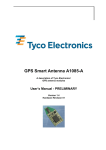
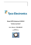
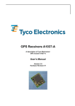
GPS Demonstration Kit USB1029A/C
A demonstration and evaluation system
for Tyco Electronics’ A1029 GPS modules
based on a USB connection
User’s Manual
Version 2.0
Hardware Revision xx
This page was intentionally left blank.
Revision History
Revision History
Rev.
1.0
1.1
1.2
1.3
1.4
1.5
1.6
1.7
2.0
Date
11-06-03
12-02-03
12-22-03
01-26-04
10-13-04
01-21-05
02-04-05
02-23-05
04-01-07
mm-dd-yy
V2.0 – 04/07
Description
Prerelease
Format change, preliminary version
Minor format changes
Introduction of schematics, top view, minor format changes
Release, minor format changes, added lists of tables and figures
Small corrections, introduction of GPS Cockpit
Introduced troubleshooting during USB installation
Introduced new contact details
Minor changes, introduction of A1029C, new design
User’s Manual
Page 3 of 17
Disclaimer
Disclaimer
THIS DOCUMENT CONTAINS PROPRIETARY INFORMATION OF TYCO ELECTRONICS CORPORATION/POWER SYSTEMS (TYCO ELECTRONICS). IT MAY
NOT BE COPIED OR TRANSMITTED BY ANY MEANS, PASSED TO OTHERS,
OR STORED IN ANY RETRIEVAL SYSTEM OR MEDIA, WITHOUT PRIOR
CONSENT OF TYCO ELECTRONICS OR ITS AUTHORIZED AGENTS.
THE INFORMATION IN THIS DOCUMENT IS, TO THE BEST OF OUR
KNOWLEDGE, ENTIRELY CORRECT. HOWEVER, TYCO ELECTRONICS CAN
NEITHER ACCEPT LIABILITY FOR ANY INACCURACIES, OR THE
CONSEQUENCES THEREOF, NOR FOR ANY LIABILITY ARISING FROM THE
USE OR APPLICATION OF ANY CIRCUIT, PRODUCT, OR EXAMPLE SHOWN IN
THE DOCUMENT.
THE PRODUCT (HARD- AND SOFTWARE) DESCRIBED IN THIS DOCUMENTATION IS NOT AUTHORIZED FOR USE IN LIFE SUPPORT DEVICES OR
SYSTEMS WITHOUT THE EXPRESS WRITTEN APPROVAL OF TYCO ELECTRONICS.
THIS DOCUMENT MAY PROVIDE LINKS TO OTHER WORLD WIDE WEB SITES
OR RESOURCES. BECAUSE TYCO ELECTRONICS HAS NO CONTROL OVER
SUCH SITES AND RESOURCES, TYCO ELECTRONICS SHALL NOT BE
RESPONSIBLE FOR THE AVAILABILITY OF SUCH EXTERNAL SITES OR
RESOURCES, AND DOES NOT ENDORSE AND IS NOT RESPONSIBLE OR
LIABLE FOR ANY CONTENT, ADVERTISING, PRODUCTS, OR OTHER
MATERIALS ON OR AVAILABLE FROM SUCH SITES OR RESOURCES. TYCO
ELECTRONICS SHALL NOT BE RESPONSIBLE OR LIABLE, DIRECTLY OR
INDIRECTLY, FOR ANY DAMAGE OR LOSS CAUSED OR ALLEGED TO BE
CAUSED BY OR IN CONNECTION WITH USE OF OR RELIANCE ON ANY SUCH
CONTENT, GOODS OR SERVICES AVAILABLE ON OR THROUGH ANY SUCH
SITE OR RESOURCE.
TYCO ELECTRONICS RESERVES THE RIGHT TO CHANGE, MODIFY, OR
IMPROVE THIS DOCUMENT OR THE PRODUCT DESCRIBED HEREIN, AS
SEEN FIT BY TYCO ELECTRONICS WITHOUT FURTHER NOTICE.
Page 4 of 17
User’s Manual
V2.0 - 04/07
Table of Contents
Table of Contents
1 Introduction .......................................................................................................... 7
1.1 Purpose............................................................................................................... 7
1.2 Contents.............................................................................................................. 7
2 Handling Precautions .......................................................................................... 7
3 Quick Start............................................................................................................ 8
4 Board................................................................................................................... 10
4.1 Overview ........................................................................................................... 10
4.2 Jumper Settings ................................................................................................ 11
5 Schematics ......................................................................................................... 12
6 Top view.............................................................................................................. 13
7 Evaluation and Demonstration Software ......................................................... 14
7.1 GPS Cockpit ..................................................................................................... 14
7.2 HyperTerminal................................................................................................... 14
7.2.1 How to open a Hyper Terminal................................................................................... 14
7.2.2 Issuing commands...................................................................................................... 15
8 DemoKit Firmware and NMEA Sentences........................................................ 15
9 Related Information ........................................................................................... 16
9.1 Contact.............................................................................................................. 16
9.2 Related Documents........................................................................................... 16
10 List of Tables .................................................................................................... 17
11 List of Figures .................................................................................................. 17
V2.0 – 04/07
User’s Manual
Page 5 of 17
Table of Contents
This page was intentionally left blank.
Page 6 of 17
User’s Manual
V2.0 - 04/07
GPS Demonstration Kits
USB1029A/C
1 Introduction
1.1 Purpose
The GPS Demonstration Kit USB1029-A/C (DemoKit) allows an easy evaluation of
Tyco Electronics' GPS module A1029-A, -B, -C, and -D. It offers quick access to
the A1029A’s or A1029–C’s serial port. Standard NMEA strings can be received,
commands can be issued, and additional information retrieved. As the A1029-B
incorporates an A1029-A and the A1029-D an A1029-C, the identical GPS
functionality is provided.
The Demonstration Kit serves two major purposes: as a demonstration packages
of the module’s capabilities and as a target system for testing and evaluating Tyco
Electronics’ GPS firmware commands and results. The Demonstration Kit is
powered through the USB connector avoiding additional power cables.
1.2 Contents
The DemoKit includes the following components:
•
•
•
•
Demonstration board (labeled USB 1029) including GPS receiver A1029-A
or A1029-C, respectively,
Active GPS antenna,
USB cable,
CD-ROM containing USB drivers, this documentation, GPS Cockpit
software.
Please check your package for completeness and connect the components
properly. See also chapter “3 Quick Start”.
2 Handling Precautions
The Demonstration Kit contains components that are sensitive to electrostatic
discharge (ESD). Please handle with appropriate care.
V2.0 – 04/07
User’s Manual
Page 7 of 17
GPS Demonstration Kits
USB1029A/C
3 Quick Start
(1) Connect the USB1029-A or USB1029-C DemoKit with your PC using the
included USB cable.
(2) When the PC asks for drivers select the folder “Tools\USB1029 drivers” of the
included CD ROM. Note that two drivers need to be installed, the USB1029
FTDI driver and the USB serial driver.
Note: During the driver installation process your Windows system will probably
notify you, that the driver did not pass Windows logo testing with a warning:
Figure 1: Windows driver installation warning
Note: After successful driver installation Windows might interpret the data
coming over the serial interface as a serial ballpoint mouse! Your mouse pointer
can start jumping around. To stop this, disable the according device using your
device manager. Leave the USB1029A/C kit connected and remove jumper J1
(see 4.1 Overview). You will find the device under “Mice and other pointing
devices”. Use a right click to open the sub-menu and disable the device.
Page 8 of 17
User’s Manual
V2.0 - 04/07
GPS Demonstration Kits
USB1029A/C
Update Driver
Disable
Uninstall
Scan for hardware changes
Properties
Figure 2: Disabling of Microsoft Serial BallPoint
(3) Connect the included GPS antenna to the USB1029-A or A1029-C
Demonstration Kit and make sure that the antenna has a good view to the sky!
(4) Copy the GPS Cockpit software from the CD to your PC. Follow the instruction
in the provided manual.
V2.0 – 04/07
User’s Manual
Page 9 of 17
GPS Demonstration Kits
USB1029A/C
4 Board
4.1 Overview
Deep Boot
enable
jumper (J3)
RX 0 / 2
selection
Jumper (J2)
TX 0 / 2
selection
jumper (J1)
Deep Boot
activation switch
Reset Button
A1029A GPS
module
USB
connector
/ NMEA
output
LED:
Serial data traffic
Connector
for active
antenna
(SMA)
LED:
1pps
LED:
GPS lock
LED:
Antenna sensor
Figure 3: Board overview
Page 10 of 17
User’s Manual
V2.0 - 04/07
GPS Demonstration Kits
USB1029A/C
4.2 Jumper Settings
Jumper
Function
Up
Down (default)
J1
Rx selection
Rx2 active
Rx0 active
J2
Tx selection
Tx2 active
Tx0 active
Table 1: Jumper settings (1)
J1 and J2 have to sit in the same position. Default setting is “Down”, connected to
the serial-USB converter. NMEA strings are transmitted via Tx0. Commands are
accepted via Rx2.
Jumper
Function
Open (default)
Closed
J3
Deep Boot
Disabled
Enabled
Table 2: Jumper settings (2)
J3 default setting is “Open” (Deep Boot disabled).
V2.0 – 04/07
User’s Manual
Page 11 of 17
GPS Demonstration Kits
USB1029A/C
5 Schematics
Figure 4: Schematics
Page 12 of 17
User’s Manual
V2.0 - 04/07
GPS Demonstration Kits
USB1029A/C
6 Top view
Figure 5: Top view
V2.0 – 04/07
User’s Manual
Page 13 of 17
GPS Demonstration Kits
USB1029A/C
7 Evaluation and Demonstration Software
7.1 GPS Cockpit
With the USB1029-A or –C DemoKits Tyco Electronics delivers its GPS Cockpit
software. This software is also available on the Internet and may be distributed
freely. For more information on GPS Cockpit please refer to the according manual.
7.2 HyperTerminal
NMEA messages can be viewed with a HYPER Terminal. Using this, you can also
transmit the TYCO proprietary NMEA commands to the A1029-A GPS receiver.
7.2.1 How to open a Hyper Terminal
START/PROGRAMMS/Accessories/Communication/Hyper Terminal
•
•
Type a name for the connection you are going to open
Select the COM port your USB1029-A or USB1029-C DemoKit occupies
(you will get this information from the device manager of you system, in the
example, COM4 is used)
Figure 6: Hyper Terminal set-up
Hyper Terminal settings:
•
•
•
•
•
Bits per second:
Data bits:
Parity:
Stop bits:
Flow control:
Page 14 of 17
4800
8
none
1
none
User’s Manual
V2.0 - 04/07
GPS Demonstration Kits
USB1029A/C
Please connect and disconnect the communication to the COM port by using the
telephone icons of the hyper terminal for assigning the new values.
7.2.2 Issuing commands
You can issue commands by simply typing the appropriate syntax on within the
Hyper Terminal window. Please verify the results by inspecting the answers.
8 DemoKit Firmware and NMEA Sentences
See separate document Tyco Electronics GPS Software for a detailed description
of the standard firmware loaded onto the module delivered with the DemoKit.
V2.0 – 04/07
User’s Manual
Page 15 of 17
GPS Demonstration Kits
USB1029A/C
9 Related Information
9.1 Contact
This manual was created with due diligence. We hope that it will be helpful to the
user to get the most out of the GPS module.
Anyway, inputs about errors or mistakable verbalizations and comments or
proposals to TYCO Electronics, Power Systems in Munich, Germany, for further
improvements are highly appreciated.
Tyco Electronics
Power Systems
Finsinger Feld 1
85521 Ottobrunn, Germany
Tel.: +49 89 6089 838
Fax: +49 89 6089 835
[email protected].
www.tycoelectronics.com/gps.
Further contact addresses:
[email protected].
[email protected].
[email protected].
9.2 Related Documents
•
•
•
•
Manual: T.E. GPS Receiver A1029 (TYCO)
Manual: T.E. GPS Firmware A1029 (TYCO)
Manual: T.E. Evaluationkit EVA1029A (TYCO)
Manual: T.E. DemoKit DKS1029 (TYCO)
•
Manual: T.E. GPS Cockpit (TYCO)
Page 16 of 17
User’s Manual
V2.0 - 04/07
Lists of Tables
and Figures
10 List of Tables
Table 1: Jumper settings (1) .................................................................................. 11
Table 2: Jumper settings (2) .................................................................................. 11
11 List of Figures
Figure 1: Windows driver installation warning .......................................................... 8
Figure 2: Disabling of Microsoft Serial BallPoint ...................................................... 9
Figure 3: Board overview ....................................................................................... 10
Figure 4: Schematics ............................................................................................. 12
Figure 5: Top view.................................................................................................. 13
Figure 6: Hyper Terminal set-up ............................................................................ 14
V2.0 – 04/07
User’s Manual
Page 17 of 17