1
1
Masterclock RC 500 User Manual – v2014.01.01
Table of Contents
The RC 500 is a remote control
timer that adds count-down and
count-up control to NTDS and
TCDS digital display clocks.
Introduction .................................................................................... 3
Installation ........................................................................................ 4
Wiring Solutions................................................................................ 5
Interface ............................................................................................ 7
Time Reference - Input/Output ........................................................ 9
Control Button Details .................................................................... 10
Count to Time ................................................................................. 12
Thank you for your purchase of a
RC 500 remote control timer
from Masterclock
Standalone Configuration ............................................................... 13
WinDiscovery .................................................................................. 16
Time Zone Offsets ........................................................................... 30
Here you’ll find instructions for
unpacking and installing your
device, proper care and
configuration.
Freewheeling Accuracy ................................................................... 31
Telnet .............................................................................................. 36
Specifications ................................................................................. 40
Problems - Trouble Shooting .......................................................... 41
We are here to help.
Limited Warranty and Service ........................................................ 46
You can reach us using various
contact methods (phone, email,
etc.) found at our website:
Certificates of Conformity .............................................................. 47
Contact Information ....................................................................... 50
www.masterclock.com
Before calling, please attempt to
find the answer to your situation
here. You’ll find this user manual
will handle virtually all of your
questions.
DISCLAIMER
The information contained in this
document is subject to change
without notice. Masterclock®, Inc.
(hereinafter Masterclock or MC)
makes no warranty of any kind
with regard to this material,
including, but not limited to, the
implied warranties of
merchantability and fitness for a
particular purpose. Masterclock
shall not be liable for errors
contained herein or for incidental
or consequential damages in
connection with the furnishing,
performance, or use of this
material. See important limited
warranty information starting on
page 38.
Masterclock RC 500 User Manual – v2014.01.01
2
Introduction
The RC500 is a programmable, single channel, timer
control unit. It remotely communicates with TCDS or
NTDS digital time displays, providing count-up, countdown and count-to capabilities.
FEATURES
•
Reference time input from NTP or stand alone with
internal oscillator
•
Modes include count-down, count-up and clock
•
Count-down mode includes a “to time” feature
•
Current mode select indicated by illuminated buttons
•
UTC, local, Daylight Saving Time or custom time
•
Control up to 6 TCDS clocks and devices simultaneously
•
Control an unlimited number of Ethernet
clocks and devices simultaneously
•
All configuration settings are retained in non-volatile
flash memory during loss of power
•
RTC (Real Time Clock) backup retains time during
loss of power or reference
•
Uses RJ12 (6P6C) modular cable to interface with
remote displays
•
Six-digit LED display counter
•
Rubber feet for tabletop use
•
Stainless steel or black powder painted case
Icons Used In This Manual
Caution: This icon signifies a potential hazard, and gives tips on how to avoid them.
Important Information: This icon indicates to an important step that must be followed.
Technical Note: This icon describes technical terms and actions.
Helpful Hint: This icon suggests the general setup and practice.
Printing
While optimized for onscreen viewing, the pages of this manual are formatted for printing on
8 1/2” x 11” and A4 sized paper, giving you the option to print the entire manual or just a specific page or
section.
Masterclock RC 500 User Manual – v2014.01.01
3
Unpacking and Installation
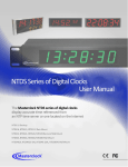
Supplied (Ship Kit)
The list below is for illustration purposes. Refer to your sales order for actual items shipped.
RC500
CD-ROM (WinDiscovery and User Manual)
Power
o AC power cord with IEC plug
o PoE uses the CAT5 Ethernet patch cable
Communications
o CAT5 Ethernet patch cable (NTDS series)
o 6P6C modular cable (TCDS series)
4
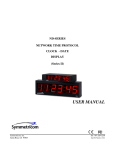
Cat5 Ethernet patch cable || CD with user manual and software || AC power cord with IEC plug
____
Masterclock RC 500 User Manual – v2014.01.01
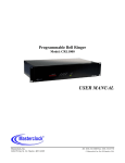
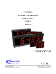
Connections
The back of the RC 500 with power and
communication sockets
IEC socket
AC power (optional)
This socket will not
appear on NTP
models
RJ12 port
RS485 communications
(TCDS series digital
time display)
RJ45 port
Ethernet communications
(NTP series digital time display)
PoE (optional)
Network Installation
5
Some users will connect their RC500
to a network for external time
reference.
Others will use their RC500 ‘as is’ by
simply plugging it in. If you do not use
network inputs, please refer to the
Standalone Instructions on page 13.
You may install the RC500 on your desk top. Attach
power and communication at the back according to
these specs:
If you ordered a PoE (Power over Ethernet) unit,
plug in the CAT5 Ethernet patch cable for power and
communication input/output to the RJ45 port.
If you ordered AC power, plug in the AC cord into its IEC
socket (customized for your country). All AC power cords
have a standard IEC female plug on one end and a
country specific male plug on the other.
When using AC power, do not also use PoE.
Instead use a 6P6C modular cable (TCDS series) for
communication input/output to the RJ12 port.
The enclosed CD contains a pdf of this User Manual and
discovery/communication/configuration Microsoft
Windows-based software called WinDiscovery. If you
have not already downloaded WinDiscovery for another
Masterclock product, you should do so now for your
RC500. See page 16.
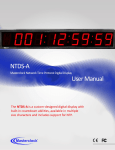
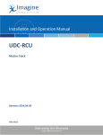
On the following page (p.6) are two sample wiring
diagram solutions using the RC500, one for NTDS along
with a TCDS digital display clock and one for only NTDS
digital display clocks.
Masterclock RC 500 User Manual – v2014.01.01
TCDS and NTDS digital display clocks
6
NTDS digital display clocks
Masterclock RC 500 User Manual – v2014.01.01
Interface
The top panel provides immediate access to all major RC500 functions. The panel consists of a 6 digit, 7
segments LED display along with three sets of pushbuttons.
Status LED
The colons on the LED display are used to alert the user of lock to time reference.
Colons Description
Flashing Time is not able to be decoded from the time reference or the
reference is not present. Time displayed on the face of the unit is
based upon internal RTC and may not be accurate.
On Solid The unit acquired valid time and has synchronized its internal RTC to
the time reference. The internal clock time is considered accurate.
7
Button Assignments
Modes
There are three mode buttons: CLOCK, UP and DOWN. Each mode performs a different operation and
is listed in the table below.
Mode Description
CLOCK Display UTC time plus any Time Zone and/or DST information.
{Standalone Menu} Exit standalone menu.
UP Perform a count up or stop watch routine.
{Clear Preset} In current mode, press to set the preset to 00:00:00.
DOWN Perform a count-down routine.
{Clear Preset} In current mode, press to set the preset to 00:00:00.
{Standalone Menu} Navigate the menu options (i.e. roll through).
Masterclock RC 500 User Manual – v2014.01.01
Interface
Set
There are three set buttons: HOUR, MINUTE and SECOND. Besides adjusting the counter preset,
the buttons are used to change settings in the standalone menu.
Set Description
HOUR Select a preset of 0 – 24 hours.
{Standalone Menu} Select a negative (-) Time Zone offset.
MINUTE Select a preset of 0 – 59 minutes.
SECOND Select a preset of 0 – 59 seconds.
8
Action
There are three action buttons: START, PAUSE and STOP.
Set
START
PAUSE
STOP
Description
Initiate or resume the count routine.
Pause the running count.
Terminate the count routine and reset preset for next routine.
Masterclock RC 500 User Manual – v2014.01.01
Operation – Input/Output
OVERVIEW
The RC500 is a programmable, single-channel, timer
control unit. The RC500 will communicate with single or
multiple TCDS and NTDS digital time displays or it may
stand alone.
RS485 COMMUNICATION
Do not connect more than one RC
500 to the same splitter. The RC500
can control up to six digital clocks.
TCDS series of digital time displays are connected to the
RC500 using the RJ12 port and a 6 wire (6P6C) straightthrough modular cable.
Time stamps are sent to the RC500 every several
seconds. The accuracy of the time is dependent upon the
referenced time in the TCDS.
To control multiple remote clock displays using a single
RC500, connect each remote clock display and the RC500
to a 6P6C male splitter (shown at left). Any remote
display connected will receive commands sent from the
RC500.
6-WAY SPLITTER
RC500 - Connect one end of a 6P6C cable to the RC500
and the other end to a splitter.
TCDS - Connect one end of a 6P6C cable to a TCDS digital
time display and the other end to the same splitter
as the RC500.
NTP (Network Time Protocol)
NTP driven clock displays are connected to the RC500 on
a local Ethernet network using the RJ45 port and a CAT5
Ethernet patch cable.
Assigning the remote clock displays to your RC500 is
done within the software application, WinDiscovery
(page 16).
Please refer to the “Configuration” section of this
document for details on using WinDiscovery and
assigning remote clock displays to a RC500.
Masterclock RC 500 User Manual – v2014.01.01
9
Control Button Details
Control Button Detail
THREE BUTTON SETS ON THE FACEPLATE
The “MODE” set controls whether you want simple clock
operation, count-up, or count-down.
The “SET” set controls the hour, minute and second.
The remaining (lower row) set starts, pauses and stops
the other two modes.
Examples
The combination of
LED display and
illuminated buttons
indicate the selected
mode and current step
being performed.
There are four modes of operation.
Clock
Count-up
Count-down
Count to Time
Below are a few scenarios of how to program and run a routine.
Clock
Press [CLOCK] to exit the “Up” or “Down” mode or the standalone
configuration menu.
Please refer to the “Configuration” section of this
document for details on the standalone menu.
Count Up
Select the mode of operation by pressing the button labeled [UP].
Enter the end number (preset) by pressing the [HOUR], [MINUTE]
or [SECOND] buttons. With each corresponding button pressed,
the digit on the display will increment.
Press [START] to send a command to the remote display and start
the routine. The display will show the running count. At the end of
the routine, the display on the RC500 and remote display will flash
three times and hold for a command.
Masterclock RC 500 User Manual – v2014.01.01
10
During a routine, press [PAUSE] to freeze the running count. To
continue, press [START] and the routine will continue from its
paused count.
To end a running count before its end number is reached; press
[STOP] and the count will reset back to the preset (i.e. end
number) and hold for the next command.
Count-down
Select the mode of operation by pressing the button labeled
[DOWN].
Enter the start number (preset) by pressing the [HOUR], [MINUTE]
or [SECOND] buttons. With each corresponding button pressed,
the digit on the display will increment.
Press [START] to send a command to the remote display and start
the routine. The display will show the running count. At the end of
the routine, the display on the RC500 and remote display will flash
three times and hold for a command.
During a routine, press [PAUSE] to freeze the running count. To
continue, press [START] and the routine will continue from its
paused count.
To end a running count before its end number (i.e. 0) is reached;
press [STOP] and the count will reset back to the preset (i.e. start
number) and hold for the next command.
Masterclock RC 500 User Manual – v2014.01.01
11
COUNT TO TIME
Select the “Count to Time” mode by pressing and holding
the [DOWN] button for 2 seconds. The [DOWN] button
should begin to steadily flash.
Enter the end real time of the count up by pressing the
[HOUR], [MINUTE] and/or [SECOND] buttons. With each
corresponding button pressed, the digit on the display
will increment. Enter the Real Time that you want to the
display to count-down toward in a 24 hour timescale.
(e.g.: if the current time is 1:05pm and you want to
count-down towards 1:30pm program the unit to 13:30.
At the end of the routine, the [DOWN] button will
continue to flash indicating the RC500 is currently in
Count to Time mode.
Press the [START] button to send a command to the
remote display and start the Count to Time. The display
will show the running count to time displaying the countdown or remaining hours, minutes, and seconds until the
preprogrammed real time. The preprogrammed real
time may reference local or UTC or whatever “real time”
was programmed into the RC500 prior to the
initialization of the count time.
You cannot freeze the Count to Time routine.
To abandon the existing Count to Time, press [DOWN]
again.
To release the display device, press [CLOCK].
RC500 will auto adjust for Daylight Savings Time and
Leap seconds. Therefore, if the RC500 is counting down
towards a time between 0200 and 0259 on the first
morning of Daylight Savings Time, the count will
advance 24 hours to the first “available” time of 02**;
because that time does not exist on that morning.
The Count to Time feature will automatically count
down towards the next real time programmed into the
RC500. Depending on the settings in WinDiscovery, the
RC500 will then perform a Count-end flash and
commence a negative count upwards from zero
removing leading zeros. Or, will then infinitely flash all
zeros.
Masterclock RC 500 User Manual – v2014.01.01
12
Custom Time Menu
There are situations where the end-user needs to display time differently than from a time reference.
When the custom time is used, the time displayed will not have Time Zone offsets or DST applied.
However the time can be displayed in 12 or 24 hour format.
Please refer to “Standalone Menu Display Properties” in the previous section of this document for
configuration of display settings.
To use the custom time feature, any external time reference (i.e. time stamp) has to be
removed or disabled. If the RC500 is receiving time stamps, it will display this time, not the
custom time entered.
To enter the custom time menu, press [CLOCK]. If you entered the
custom time menu accidently, press [CLOCK] to cancel and return to
clock mode.
Enter the time, in 24 hour format, by pressing the [HOUR],
[MINUTE] and [SECOND] buttons until all dashes (--) are replaced
with digits. With each corresponding button pressed, the digit on
the display will increment. Press and hold to enter a rapid
movement.
Press [CLOCK] to exit the menu and display the custom time.
If dashes (--) are displayed, the time will not be set and the display will revert back to the
internal RTC time.
When the custom time is no longer needed, there are three ways to restore time.
Receive time stamps from TCDS or lock to a NTP time server
Cycle power by removing the AC power cord for a few seconds
Reset RC500 to factory defaults
Please refer to “Reset Configuration to Factory Default” in the next section of this document for
details on resetting the RC500. All user configurations will be cleared.
Masterclock RC 500 User Manual – v2014.01.01
13
Standalone Menu Display Properties
The RC500 can be customized to display time in a variety of formats
and brightness levels.
Default Settings
To enter the configuration menu press and hold [CLOCK] for
approximately 2 seconds.
br::
Press [DOWN] to cycle through the configuration menu.
Press [HOUR], [MINUTE] and [SECOND] to change settings.
Press [CLOCK] to exit the configuration menu.
SP::on
Each menu setting will be saved until a user makes a change to the
setting or the unit is reset to factory default.
hr::
Factory default settings are:
L::
Brightness:
Speaker:
Time Display Format:
Time Zone Offset:
Daylight Saving Time:
Time Displayed:
Leading Zero:
4
On
24 hour
0
Off
Local
Off
Brightness
This setting controls the brightness of the LED display and
illuminated buttons.
There are four levels of brightness.
Brightest: 4
Bright: 3
Dim: 2
Dimmest: 1
dS::off
::Loc
::off
t
br::
:
:
:
SP::on
:off
___________ _
___________
___________
Speaker
When enabled, the unit will emit a short audible tone (3.7kHz)
during initialization and at the end of each timer count.
When speaker is set to off, the unit will continue to emit a
short audible tone during initialization.
Masterclock RC 500 User Manual – v2014.01.01
_____
___
14
Time Display Format
The unit can display time in 24 or 12 hour formats. When set to 12
hour format, the AM/PM indicator will be on during the PM hours.
hr::
_______
Time Zone Offset
To have the unit display time other than UTC, press [HOUR] to
select positive (+) or negative (-), press [MINUTE] to select the hour
and press [SECOND] to select the minutes.
Daylight Saving Time
There are three options for DST settings. For information of
standards for United States/Canada and European Union DST,
please refer to the section, “Daylight Saving Time” in the previous
section of this manual.
Time Displayed
In addition to time zone offset, the display can show UTC or local
time (i.e. time zone offset + daylight saving time).
::
__
::
dS::off
________
:EU
________
:US
t::Loc
______
Leading Zero
This feature will allow a “0” to be displayed for the first digit,
between the hours of 1 and 9.
:
L::
_
Do not adjust for DST in Time Zone Offset. Set DST from
the next menu setting, Daylight Saving Time.
_
:UtC
0::off
_______
:on
The RC500 “Display Properties” will not affect the
remote clock display settings.
Changes made using WinDiscovery will over-write the standalone settings and vice
versa.
Masterclock RC 500 User Manual – v2014.01.01
15
Installation
The WinDiscovery software application is a program designed to run under the Microsoft Windows
operating system and is supplied with the network clock. To install the WinDiscovery program on your
server/workstation/personal computer, complete the following steps:
1. Insert the CD that shipped with your network clock.
2. Run the “setup.exe” application from the CD.
3. By default, the setup utility will suggest installing files to
C:\Program Files\Masterclock\WinDiscovery.
4. Click the [OKAY] button
16
Masterclock RC 500 User Manual – v2014.01.01
WinDiscovery Installation and Operation
Using WinDiscovery
Open WinDiscovery from the “Start Menu” or by double-clicking the shortcut icon on the desktop.
Once you click [Discover], shown below, all network clocks accessible on the network will announce
their presence and the status bar will display the count of devices found. When complete, a list of
device families and groups will be displayed in the left pane of the WinDiscovery window. RC500 will
be displayed along with any other devices that are on the network
.
17
Click [Discover] to view NTP devices on your network.
Each clock is configured with a device name from the factory. This name includes the model name and a
“MAC address” (Media Access Control) extension. You can change the device name to one convenient for
your site – preferably one that helps you to later identify the exact physical location of the device.
It is highly recommended that only one user uses WinDiscovery at a time and other methods
should not be used to manage the network clocks while using the WinDiscovery software
application.
Masterclock RC 500 User Manual – v2014.01.01
Click on the plus [+] sign to the left of any family or group to open and view device types that were
found. Click on the minus [-] sign to close and not show the device family or group.
Click on any device group and it will list the devices in the right pane with all devices of that type
found. To configure another device group, click on the device name in the left window and the
device names will then appear in the right window, ready to be managed.
18
Right click the device name and the properties window will open. Click on a menu choice to open
the window for that function.
The choices are:
Properties
Network Settings
Device Settings
Set Password
Set Time/Date
Status
Reset Device
Use the [Cancel] button to exit the screen without applying changes.
Masterclock RC 500 User Manual – v2014.01.01
Below: This menu appears following a
right click on device name.
INSIDE THE DROP DOWN MENU WINDOW:
PROPERTIES
Click the [Properties] button to view the “Properties”
window (middle left). This presents a summary of the
current Network Configuration and cannot be changed
except through the other windows.
NETWORK CONFIGURATION
The network configuration (middle right) may be viewed
in summary by clicking the [Network Configuration]
button.
Properties Window
DEVICE SETTINGS
The “Device Settings” window (pg. 22) configures the RC
500 to receive and display in the format that you prefer,
using Time Zone offsets and DST settings to completely
customize it relative to UTC time.
The top right section of the “Device Settings” window
shows a list of the firmware and options associated with
your RC 500.
Network Configuration
The rest of the “Device Settings” window includes access
to all configuration options for the network. These
include time reference inputs and outputs, display
properties, relay control and administrative functions,
such as password. There is also a status display to
monitor remote clocks and devices from your computer
screen using the free, included WinDiscovery software
application.
Any changes made in this window, including all the
buttons thereon, will not be applied until you click the
[Save] button or the [Save and Close] button, prior to
clicking the [Exit] button.
SET PASSWORD
Each Masterclock device in your network may have its
own password (see the “Properties” window to [Set
Password]) or you may create a Global Password on the
“Discover” window. The default password is “public”.
Your custom password should be one to eleven
characters and is case-sensitive. For added password
strength, you should use both alphanumeric and special
ASCII characters.
The password must be entered twice to confirm the
entry. Click [Change Password] to save it.
Masterclock RC 500 User Manual – v2014.01.01
19
When a password is set for a device, each time you click
[OK], [Apply] or [Apply and Close] for that device you
will be asked for the password. You can select the
[Remember this password for the session] button and
you will not be prompted for the password, until you
restart WinDiscovery. Or you can use the Global
Password feature (see below).
If you enter the wrong password and selected the
[Remember this password for the session] checkbox,
you will receive an error upon clicking [OK], [Apply] or
[Apply and Close] to any configuration changes. You can
close the WinDiscovery session to forget the wrong
password(s). However, this will require entering the
password(s) again for each device.
You can also remove the incorrect password entry during
a WinDiscovery session by going to the drop-down menu
for the device (right click to see this) and selecting the
[Forget memorized password] button.
Global Password
The global password feature allows the user to enter a single password for all NTP devices using the same
password. During this session and subsequent sessions of WinDiscovery you will not have to enter the
password.
20
To use global password, click [Global Password] from the main window of WinDiscovery.
The global password being used must match the password on all the devices being administered.
For example, on any new system being installed, the factory default password on all devices is
“public”.
Masterclock RC 500 User Manual – v2014.01.01
Enabling / Disabling Global Password
1. Enable the global password feature by selecting the “Enable Global Password” checkbox.
2. Type the global password
3. Click [OK]
Select by
clicking
To disable the Global Password, de-select the “Enable Global Password” checkbox and click [OK].
SET TIME/DATE
Click the [Set Time/Date] button and a window appears
reminding the user, “This feature is only to be used to
set the UTC time and date if the device is not locked to
a reference and is free-wheeling. “ Other cautionary
remarks follow. At the bottom of the window you may
choose to continue or not. If you choose the [Yes]
button, the “Set Time/Date” window appears, also seen
on page 32.
STATUS
See “Status” window, page 34.
RESET DEVICE
See ”Reset Device” window, page 32.
MANAGING DEVICE
To open “Device Settings” and show [Configurable
Options] buttons, double left click on device in
“Discovery Window”
Masterclock RC 500 User Manual – v2014.01.01
21
Device Settings
The device settings window will display network device and can be configured to display time in the
format that you prefer, using time zone offsets and DST settings to completely customize it relative
to UTC time.
The top right section of the Window shows the current firmware version and serial number of the
device.
22
When working in these management windows use the [Apply], [Apply and Close] and [OK] buttons
to accept changes that you have made. Any changes made in these windows will not be saved until
you click the [OK] to exit the window or the [Apply] or [Apply and Close].
Use the [Cancel] button to exit the screen without applying changes.
INPUT CONTROL
The [Input Control] button provides access to
the “Input Control” window, which provides
button for NTP Client.
Device Settings – Input Control is circled.
Clock Control is surrounded by yellow.
Masterclock RC 500 User Manual – v2014.01.01
NTP CLIENT
While on the “Input Control” window, click the [NTP
Client] button to access settings for the NTP client.
ENABLE NTP CLIENT – is enabled by default. However, it
may be desirable to disable the NTP client for certain
applications, such as those in which the RC 500 will
not reside on a network during typical operation.
Deselect “Enable NTP client” if desired.
The network client can be configured to either query
the NTP time server at a selected interval, to listen to
NTP broadcasts only, or to listen to multicast
broadcasts.
NTP CLIENT SETTINGS
QUERY NTP SERVER FOR TIME – is enabled by default.
This is the unicast mode. The default configuration is
to query the NTP server at 10-second intervals.
The NTP settings are located in the upper left-hand
section of the window. The Primary reference
information must be configured in order to acquire
time from an NTP reference.
Enter either the IP address or Internet address/URL
(Uniform Reference Locator) for the NTP reference.
If available, enter a secondary reference for backup.
The primary and secondary server information can
automatically be configured by the DHCP server
when selecting the “Use NTP server(s) address
provided by DHCP server” provided your DHCP
server is configured to do so. Consult your network
administrator to use this option.
By default, the NTP clock will operate only in
Unicast/Query mode using server port 123.This
mode is selected exclusively when neither the listen
for NTP broadcast nor the listen for NTP multicast
modes are selected.
Masterclock RC 500 User Manual – v2014.01.01
23
Listen for NTP via broadcasts address
The network clock can be configured to listen to NTP broadcasts by selecting the
“Listen for NTP via broadcast address “255.255.255.255” checkbox.
Select by
clicking
24
The Broadcast timeout period is adjustable when this mode is selected.
The default configuration is to query the NTP server at 10-minute intervals. The clock drift is +/- 1
minute per year, so you can adjust as need. To configure the network clock device to only listen to
NTP broadcasts, click the checkbox for “Listen for NTP broadcasts only” and enter a “Broadcast
timeout” in minutes. The default timeout is 60 minutes.
While listening to NTP broadcasts/multicasts, the network clock cannot be configured to query
the time server.
Some NTP/SNTP clients will expect NTP servers to operate on port 123 and cannot be configured
to use alternate ports.
Masterclock RC 500 User Manual – v2014.01.01
Listen for NTP via multicast address(s)
The network device can be set up to listen to NTP using multicast addressing by selecting the
“Listen for NTP via multicast address(s)” checkbox.
Select by clicking
25
When enabled, the multicast class D / group address may be specified as well as the frequency that
multicast broadcasts will be issued. This can be changed as desired. The network clock can listen for NTP
multicast broadcasts using the full class D/ group address range. The network clock does not restrict the
use of the multicast address assignment and supports the full range of class D multicast addresses or
groups from “224.0.0.0” to “239.255.255.255”. These groups or class D address ranges for multicasting
are defined and governed by RFC3171, IANA IPv4 Multicast Guidelines.
Typically, the multicast address range “224.0.1.0” – “224.0.1.255” (Internetwork Control Block) is used
for NTP traffic; however, please refer to the RFC3171 for your specific application and implementation.
While listening to NTP broadcasts/multicasts, the network clock cannot be configured to query
the time server.
Some NTP/SNTP clients will expect NTP servers to operate on port 123 and cannot be configured
to use alternate ports.
Masterclock RC 500 User Manual – v2014.01.01
NTP SERVER NAMES – By default the [Use NTP server
provided by the DHCP server] box is checked and a
primary NTP server address is displayed. If you wish
to uncheck the box and provide your own server
addresses for both primary and secondary servers,
do so here.
NTP CLIENT AUTHENTICATION SETTINGS – This
window permits the entering of up to 15 MD5 key
values to be trusted or allowed. Primary client
settings permit the entry of a primary server key
number, a secondary server key number and a
broadcast key number.
NTP ADVANCED SETTINGS – Under most typical
operating circumstances it is not necessary, nor is it
suggested, to change the “Advanced Settings”
options.
NTP ADVANCED SETTINGS PARAMETERS
This allows for setting the NTP mode and parameters of the SNTP client in the network clock.
The default TCP/UDP port for NTP service is 123.
26
Some NTP/SNTP servers will expect NTP clients to operate on port 123.
Masterclock RC 500 User Manual – v2014.01.01
NETWORK CONFIGURATION
The “Network Configuration” window may be viewed in
summary by clicking the [Network Configuration]
selection.
DISPLAY PROPERTIES
In the “Display Properties” window (below), you can change the brightness of the display or modify the
presentation of the date and time. You can change the display from UTC to local time and you can
alternate times with dates and set the rate at which they change.
27
Display Control
The upper left-half corner allows you to adjust the brightness of the LEDs and button illumination.
The options in this configuration region may be grayed out; this indicates unavailable options for this
model of network device.
Masterclock RC 500 User Manual – v2014.01.01
COMMUNICATIONS CONTROL (TELNET OPTION)
Certain advanced features may be configured using the
[Communications Control] button. This gives access to
the “Telnet Control” window (below). If Telnet is
allowed, the port must be defined. The default Telnet
port is 23. See your network administrator if you need
additional information.
CLOCK CONTROL SETTINGS
Click the [Clock Control Settings] button to access the
RC500 “Clock Assignment” window.
Use this menu to configure which remote NTP clock displays will respond to the RC500 commands. The
list in the left column is the available clock displays and the right column show the devices assigned to the
RC500.
Masterclock RC 500 User Manual – v2014.01.01
28
Use the buttons located in the center to move a device from the “Available” to the “Assigned” column.
Move all available clock displays by pressing [All >] and [< All] respectably and [>] and [<] to move
individual clock displays. When finished, click [Ok] and the assignment will be saved.
29
Clear All Device Assignments / Reset All Control Assignments
This feature allows the end user to clear all RC500s and clock displays association.
By clicking [OK], all RC500s and clock displays on the network will have their assignments
cleared. This is a global “clear all” and in order for a RC500 to control a clock display, it will
need to go through the “Clock Assignment” configuration.
Masterclock RC 500 User Manual – v2014.01.01
TIME ZONE/TIME OFFSET SETTINGS
Click the [Time Zone/Time Offset] button to open the
“Time Zone Configuration” window. This window
displays a list of time zones, including descriptions to
help with the selection. Select the offset and click [OK] to
close the Window. The DST rules will be applied when
you click [Apply] or [Apply and Close] from the “Device
Settings” window.
DAYLIGHT SAVINGS TIME SETTINGS
Click [Daylight Saving Time] to open this window. The
clock has complete flexibility to display any Time Zone
and DST combination.
For setting the DST rules, use one of the following
options.
1. Manually enter the Daylight Saving Time rules; or
2. Click the [US/Canada Standard] button; or
3. Click the [EU Standard] button.
4. Then click [Current Windows Setting] to apply the
current configuration for your Windows OS.
5. Click [OK] to close the Window.
The DST rules will be saved when you click either the [Apply] button or the [Apply and Close] button on
the “Device Settings” window.
US/Canada DST standard
EU DST standard
Masterclock RC 500 User Manual – v2014.01.01
30
Time Zone Offsets
The RC500 interprets time
input as UTC. If the time
reference to this unit is not
UTC, do not adjust the Time
Zone and/or DST offset.
A Time Zone offset or bias can be used to adjust the
time for display purposes because the default is UTC
time. Local or custom time can be set as a positive (+)
offset indicating that the unit is earlier than UTC time or
negative (-) offset indicating the unit is later than UTC
time. See page 30.
DAYLIGHT SAVING TIME (DST)
An automatic DST setting can be configured separately
and in addition to a Time Zone offset. The RC500
provides flexible configuration options supporting most
DST standards through the Configuration Menu (p. 30).
To ensure proper handsfree year-around operation,
DST adjustments must be
configured using the
“Daylight time” option and
not with the “Time Zone
offset” option.
USA and Canada
DST begins on the second Sunday of March at 2:00 AM
(Local Time) and end the first Sunday of November at
2:00 AM (Local Time).
EU Standard – European Union
Summertime period begins at 1:00 AM UTC on the last
Sunday of March and ends at 1:00 AM UTC on the last
Sunday of October.
Please carefully consult the section entitled “Device
Settings” (p. 13 for Standalone and p. 22 for Network
input) for details on setting DST.
Freewheeling Accuracy
The RC500 has built-in provisions to allow its internal clock to freewheel and maintain accuracy
for extended holdover periods in the absence of a reference. You can also set the unit manually
(Standalone Configuration) and operate without a reference input.
TCXO AND RTC CIRCUIT
The RC500 contains a precision TCXO and RTC circuit allowing the clock to maintain an accuracy
of ±1 minute per year to the last known Time Code input (±165 mS per day) when a time
reference is not preset or cannot be decoded (i.e. freewheeling mode).
MAINTENANCE-FREE RECHARGEABLE BATTERY
The RTC and TCXO are maintained continuously from a rechargeable battery circuit during
periods of power outage. Minimum holdover period is two weeks with a fully-charged battery.
The battery automatically charges whenever the unit is powered and it requires no maintenance.
NON-VOLATILE CONFIGURATION
Masterclock RC 500 User Manual – v2014.01.01
31
The configurations you set are maintained in non-volatile memory allowing your custom settings
to be retained during power outages.
ADMINISTRATIVE FUNCTIONS (AF)
Click the [Administrative Functions] button to open a
menu that is rarely accessed. These include: 1. [Set
Time/Date] (for custom time, not UTC or local time); 2)
[Set Password]; 3) [Reset Device]; 4) [Install New
Option]; 5) [Leap Second Date] (input this whenever
announced); 6) [Email Configuration] (to automatically
alert you via email of any situations within the system
when they happen). Below we’ll look at these windows
in detail.
SET TIME/DATE WINDOW
There may be situations where you do not want to
display UTC or local time. This feature may be most
useful for demonstrations, in lab situations or in
environments where an external reference time signal is
not available. Use this when the built-in NTP client is
disabled or when a network connection to an NTP server
is not available.
Click the [Set Time/Date] button to reset the time to
your preference. You will be prompted with some
additional instructions then offered the choice to
continue. Click [Yes].
In the “Set Time and Date” window (left) click the
[Custom] button to enter your new time and date. Click
the [Set Now] button to activate your custom time. To
return to UTC time choose [UTC Time and Date button
from the PC clock] then click [Set Now].
SET PASSWORD (See pg. 19)
RESET DEVICE
Click [Reset Device] to induce a soft reset. This
procedure allows the RC 500 to clear its current
communications buffer and re-initialize its processing,
which includes another software request for a DHCP
address. This feature is intended to allow the user to
remotely reset the unit and does not restore the factory
default state.
Alternatively, if you are not in the “Administrative
Functions” window, but are viewing the list of devices
after pressing the [Discover] button, simply right click on
the device you are interested in and select the [Reset
Device] button.
Masterclock RC 500 User Manual – v2014.01.01
32
Soft Restarts
A soft restart may periodically be performed by the network device to automatically attempt to rectify a
problem it may be experiencing. A soft restart is essentially the same as performing a manual soft reset
device as described above.
The network device will perform a soft restart under the following conditions:
If the device is not receiving an NTP poll response or an NTP broadcast response depending on
which mode the device is in.
If the device is set to use DHCP and no DHCP server can be found.
The timeout before doing a soft restart is not less than 10 minutes. Several factors can increase the time
between these soft restarts.
The soft restart will be delayed by two hours if a connection is made by telnet or WinDiscovery.
The soft restart is delayed if the user changes the default parameters for NTP poll
retries/timeouts or the NTP broadcast timeout. For example, if the NTP broadcast timeout is
increased to 60 minutes the soft restart timeout will also be increased to 60 minutes.
Reset Configuration to Factory Default
In some situations it may be necessary to return the unit to factory default settings. The unit will go
through an initialization process. Next, the RC500 will show the time on the display.
33
SET TO DEFAULT CONFIGURATION
Click the [Set to Default Configuration] button to reset
all of your previously entered options and customs
settings back to the original factory settings. You will get
the “Are you sure?” window. Click the [Yes] button if you
are sure you want to return to the default configuration
with the default password: “public”.
Default Settings
Brightness:
Speaker:
Time Display Format:
Time Zone Offset:
Daylight Saving Time:
Time Displayed:
Leading Zero:
Display dashes:
4
On
24 hour
0
Off
Local
Off
Disabled
Masterclock RC 500 User Manual – v2014.01.01
Reset Configuration through pinhole
1. Located on the rear of the unit is the pinhole to the reset
button (i.e. next to the RJ45 Ethernet port).
2. While the unit is powered on, insert a non-metallic reset
tool straight through the pinhole and hold the button for
proximity 5 seconds or until the display shows dashes.
Reset button through pinhole
The unit will go through an initialization process and will show the time on the display when reset is
complete.
STATUS
At the bottom left of the “RC 500 Device Settings”
window is the [Status] button. The “RC 500 Status”
window includes a “Display Snapshot” of a graphic
digital clock representing the face of the actual RC 500 in
real time. On the right appear the “UTC Time” and date,
“Local Time” and date, the “Current Reference” signal
(in this case GPS), the “Reference Status” (in this case
“Locked”) and two windows listing “Last Time Lock Lost”
and “Last Time Lock Restored.”
34
Below these listings are tabbed windows for “Network,”
“NMEA,” “and “NTP.”
Network Tab ─ includes the name of the device, the
model of the device and a summary of the network
configuration, much of this data is repeated from the
network configuration window described earlier
(page 20).
NMEA Tab ─ Default set to enabled.
NTP Tab ─ includes a checkbox for an enabled NTP
server, plus the number of NTP requests service and
the server stratum. Also includes a checkbox for an
“Enabled” NTP client including indications for the
“Active Server,” the “NTP Status,” the “Last NTP
Time Stamp,” the “Largest Time Adjustment” and
the “Average Time Adjustment.”
The Status window is a display-only window that gives you the current information on the network
device and synchronization activity. This status update is not precise, but is intended to give you a
view of the device display for troubleshooting purposes. The Status also shows the active NTP
server; primary and/or secondary, the current synchronization status and time adjustment
information.
Masterclock RC 500 User Manual – v2014.01.01
Time adjustments are changes to the internal time reference as compared to the NTP server.
1. While acquisition of NTP server.
Initial startup
After loss of power
After loss of NTP
2. Change to the device configurations.
Network Configuration
Reset Device
35
In addition to the standard status indications, the network device will display a special error
indicator under the status window if either a DHCP server cannot be located, or if the device has
an IP address conflict due to either DHCP or Static IP addressing. Under these conditions the
unit will also be assigned a fallback IP address of “169.254.xxx.xxx”, and appear in RED text
under the main WinDiscovery window. To determine the cause of why the device received a
“169.254.xxx.xxx” address the user should display the status of the clock. Near the bottom of
the Status window the error will be displayed
Masterclock RC 500 User Manual – v2014.01.01
Telnet
Those with Linux and other non-Windows operating will not be able to use WinDiscovery.
Configuration via Telnet may not
be convenient for devices operating
with a factory default configuration
since the IP address is not known. Use
the WinDiscovery application to
establish first-time networking
configuration.
A terminal-style configuration interface is available
via Telnet. To connect with the network device in
this manner use any standard Telnet client
application, specifying the IP address of the clock as
the server with which to connect.
For security purposes, the
Telnet interface can be disabled.
When disabled, you will no longer be
able to access the device with Telnet.
To re-enable the Telnet feature, one
of the other configuration methods
must be used, or the clock must be
reset to factory default.
By default, Microsoft Windows 7 has the Telnet Client
disabled.
If you are not familiar with
Telnet, ask your network
administrator for assistance.
The factory default port is Telnet server port 23.
TO INITIATE A TELNET SESSION IN WINDOWS
Select the Run command-line interface from the Start
menu and enter the command “Telnet” followed by a
space, and then the IP address of the unit and click [OK].
TO ENABLE TELNET IN WINDOWS
Open the Windows Control Panel, click on [Programs],
click on [Turn Windows features on or off], check [√]
Telnet Client and click [OK].
.
TO ENABLE TELNET IN LINUX
See your system administrator.
By default, Microsoft Windows 7 has the
Telnet Client disabled. To enable, open Control
Panel, click on “Programs”, click on “Turn
Windows features on or off”, check [√] Telnet
Client and click [OK].
Masterclock RC 500 User Manual – v2014.01.01
36
TELNET
A login prompt is
presented if a password
has been configured for
the device. The
configuration menu will
be displayed when the
correct password has
been provided.
The factory default
password is: “public”.
Type “?” to display the screen
at left.
(See this and commands like
this at the bottom of the
Telnet screen at left.)
37
Type “help” to display the
abbreviated screen at left.
Type the command name
corresponding to the desired
action (such as “timezone”
then press [Enter] or [Return].
Follow the command with a
“?” to show more options and
the command string.
Shown at left, “timezone”
command with results and
“timezone?”command with
results.
Masterclock RC 500 User Manual – v2014.01.01
TELNET CURRENT CONFIGURATION/
DEFAULT SETTINGS
Current configurations default
settings are displayed.
Depressing the [Enter]/ [Return] key
with no number or letter will retain
the current setting.
Depressing the [Enter] or [Return] key with no number
or letter will retain the current setting.
brightness ─ Default: 4
Show or change the Brightness level of the LED display
and button illumination.
debug ─ Default: Disabled
Show or change the debug output settings.
It is recommended that a robust
naming scheme be developed before
devices are installed to different
locations within an organization.
If Telnet is turned off while in a
Telnet session, the network device will
reboot and the session will end.
To enable Telnet access, either “Reset
to Default” or use WinDiscovery and
from the “Device Settings” window,
click [Communications Control],
[Telnet Control] and check [√]
“Allow Telnet Configuration.”
devicename ─ Default: RC500-xx:xx,
where xx:xx is the last four characters of the MAC
Address.
Show or change the device name.
dhcp ─ Default: Enabled
Show or change the DHCP settings.
dst ─ Default: No
Show or change the Daylight Saving Time settings.
display ─ Default: 24-hour
Show or change the display format.
38
exit
Exit the current telnet session.
mcast ─ Default: Port 6168
Show or change the multicast control settings.
netstat
Show the device’s network properties.
network
Show or change an IP setting. The device will restart.
ntpclient
Show or change the NTP Network Time Protocol settings.
ntpclientadv
Show or change the NTP Client advanced settings.
password - Default: public
Show or change the password.
ping - Ping to a specified host
This is useful in situations where the communication
path from the network clock to the NTP server is in
question.
properties
Show the device properties.
Masterclock RC 500 User Manual – v2014.01.01
reboot
Reboot the device
reflossdashes
Show or change displaying dashes on reference loss
settodefault
Reset the device to factory default or restart
Speaker - Default: On
Show or change the speaker output setting
status
Show status information by querying the device
parameters. This includes information regarding the
reference to UTC, local time, displayed time, whether it
is synchronized, etc.
telnet - Default: 23
Show or change the Telnet port and/or turn off Telnet
access.
time
Show or change the time and date. This is useful in
situation where NTP server synchronization is not
available but reasonably correct time/date is desired on
the display. When the network device has access to NTP
servers, information obtained via NTP will automatically
overwrite any manually established time/date.
Therefore, practical use of this feature requires the
device to be removed from the network or for NTP
server configuration to be left undefined.
timezone - Default: UTC
The Time Zone Bias indicates the offset from UTC. Enter
the time in HH:MM:SS format as indicated, including the
plus or minus sign to indicate positive or negative bias.
Remember that this field can also be set from DHCP, so
check with your network administrator if you are getting
inexplicable results.
zeros - Default: Off
Show or change the leading zero setting.
?
Displays the list of Telnet commands.
/?
Follow a command with “/?” to see specific help for that
command.
help
Displays brief help when followed by a command.
Masterclock RC 500 User Manual – v2014.01.01
39
Specifications
Communications I/O
Connectors
RJ12 .................................................................. RS485 communication with TCDS Digital Time display
RJ45 .................................................................. Ethernet communication with NTDS Digital Time display
Power
AC
Voltage ............................................................ 100-240 VAC
Frequency ......................................................... 50/60 Hz
Consumption .................................................... 5 W
Connector ......................................................... Universal IEC input connector
PoE
RJ45 .................................................................. PoE (Power over Ethernet)
There are no user serviceable parts inside the RC500 Timer Control Unit.
Please contact Masterclock, Inc. if you require servicing or repair.
40
Internal Battery Circuit
Maintenance Free Rechargeable Battery
3V,17 mAh, Coin Cell
Rechargeable Manganese Lithium
Panasonic ML1220/V1A
Rechargeable Manganese Lithium coin cell (Panasonic ML1220) and recharging
circuit requires no maintenance and retains all configuration settings for two weeks
(minimum holdover) without applied external power.
Operating/Storage Temperature and Humidity
Operating Temperature ............................... 32˚ to 140°F (0˚ to 60˚C)
Relative Humidity ......................................... 0 to 90%, non-condensing
Storage Temperature ................................... -40° to 185°F (-40° to 85°C)
Size and Weight
Width ............................................................
Length ...........................................................
Depth ............................................................
Weight ..........................................................
6.82” (17.32cm)
5.24” (13.31cm)
2.37” (6.02cm)
2.2lb (35.2oz)
Masterclock RC 500 User Manual – v2014.01.01
Problems - Troubleshooting
Unable to communicate to slave display / clock
Possible reasons/solutions:
1. Verify the correct RJ12 (6P6C) modular cable is being used (i.e. 6 conductor).
2. Verify all connections are secure between the RC500 and slave display/clock.
3. Check to make sure power is applied to all devices.
4. Check the cables for hard bends, kinks, or cuts.
5. Verify that the correct adapters and splitters are being used (i.e. 6P6C).
Colons are flashing / Time is incorrect
Possible reasons/solutions:
1. The RC500 is not currently connected to a valid time reference.
2. There is a problem with the cabling between the RC500 and the time reference. Verify that all
cables and connectors are in good condition.
Unable to lock to time code
Possible reasons/solutions:
1. RC500 is not currently connected to a valid time code source.
2. Verify that all cables are properly connected.
3. Verify that all cables and connectors are in working condition.
4. The time code format being fed to RC500 is not recognized format.
5. Verify the time code reference is a format supported by the RC500.
6. Signal level of time code is not at acceptable levels.
Not displaying the correct local time.
Possible reasons/solutions:
1. The unit is not receiving time code. Verify that the colons on the LED display are on solid.
2. The time reference is referenced to UTC but your local time zone reference of your time
reference and then set the time zone offset to arrive at a correct local time.
3. If the time reference is already providing time with local time zone and/or DST offsets, then set
the time zone and/or DST offset of the RC500 to UTC. If the time reference is providing UTC
time, then configure your RC500 to have a local time zone and/or DST offset.
4. Your time reference is not providing the time/date that you expect. Contact the individual
responsible for the time reference for more information.
DST is not properly negotiated
Possible reasons/solutions:
1. Verify the DST is enabled on RC500
2. Verify that the correct format of DST is enabled (US/EU).
3. Check to make sure that you do not have DST enabled on both clocks and RC500.
Unable to discover the RC500 using WinDiscovery.
Possible reasons/solutions:
1. Verify that you have supplied power to the network device.
2. The discovery process was not complete. “After selecting the Discover” button, wait until the
discovery status indicates 100% completion.
3. Verify that the RC500 is on the same physical network as the computer from which you are
running WinDiscovery.
Masterclock RC 500 User Manual – v2014.01.01
41
4. If the computer is separated from the device by a router (on a remote network) or a firewall it is
likely that the router/firewall is blocking communications with the device. Run WinDiscovery
from a computer within the remote network, or ask a network system administrator to configure
the router/firewall in question to pass through (both directions) UDP broadcasts on port 6163.
[Note: If this does not resolve the detection problems you may additionally configure to pass
through both directions UDP broadcasts on ports 6165, 6166, and 6364]. Some routers will not
forward UDP broadcasts across networks-currently; this capability is required to use
WinDiscovery for enterprise-level management of Masterclock, Inc. network appliances. If you
are running a personal firewall product, such as Zone Alarm or Black ICE, or the built in Windows
firewall you must adjust their configuration to pass through (both directions) UDP traffic on port
6163.
5. Verify that the hub/switch/router is capable of supporting the 10MB speed that the attached
network device requires.
6. Verify that the network device and the computer running WinDiscovery are attached to the
network.
7. Verify all network cables; hubs, etc are in proper working order.
No response to configuration changes under WinDiscovery / garbled characters
Possible reasons/solutions:
1. The WinDiscovery application has been open for too long and the device’s configuration(s) has
(have) changed. For the example, this can occur if the DHCP server has issued new/refreshed
addresses. Close the WinDiscovery application and restart.
2. The discovery process was not complete before selecting device. After selecting “Discover”
button, wait until the discovery status indicates 100% completion.
3. Verify that the physical network cables and equipment and configuration for UDP have not
changed.
4. Verify that you are currently the only user accessing the device via WinDiscovery or Telnet.
5. The network may currently be experiencing heavy traffic which is reducing bandwidth and/or
causing collisions with the UDP messages/packets between the device and WinDiscovery. Since
delivery of UDP messages are not guaranteed, this can cause WinDiscovery to not receive the
latest configuration or status packets, and thus show outdated or garbled information. In some
cases, the device may not be discovered and displayed in the WinDiscovery device tree.
RC500 appears in RED text under WinDiscovery device tree
Possible reasons/solutions:
1. Incorrect network configuration may be causing the device to receive a fallback IP address and or
perform soft restarts. Verify that the IP address configured for the device is correct. If you
manually enter (or DHCP assigns) and IP address that already exists on the network, this will
create an IP address conflict. The device will reset its address (fallback) to one within the linklocal address space. Determine the cause of fallback IP address and resolve issue. View the error
status under the status window to help determine the cause of why the device received a
169.254.xxx.xxx. Near the bottom of the status window the error will be displayed. (If there is no
error the text box will not be displayed.)
Devices which have been assigned a fallback IP address of 169.254.xxx.xxx will be displayed in
the main WinDiscovery window with RED text, indicating a problem with the configuration.
2. When the Ethernet Interface is initialized the network device will verify the IP address (either
Static or assigned by DHCP) is not being used by another device on the network. If a conflict is
found the device will default to a 169.254.xxx.xxx address. The IP address that caused the error
Masterclock RC 500 User Manual – v2014.01.01
42
is saved and returned as an error to WinDiscovery. This error status is available to the user via
the Status window on WinDiscovery.
If the configuration of the network device is changed while a 169.254.xxx.xxx is being use, then
the current 169.254.xxx.xxx address will become the permanent static address and the original
conflicting static address is lost. At this point, it is necessary to manually change the static IP
address to one that will not conflict, or you may do a “Reset Configuration” to restore the
system to factory default settings.
3. If DHCP was selected and the network device fell back to a 169.254.xxx.xxx address
approximately every 10 [depending upon the “Advanced Setting” values] minutes the Ethernet
interface will be reinitialized and the RC500 will attempt to get an IP address from the DHCP
sever. If the device is successful, the error will be cleared and the new address from the DHCP
server will be used. If a discovery was done using WinDiscovery or Telnet was used this
initialization will be delayed by 1 hour.
RC500 appears to ‘reset’ periodically
Possible reasons/solutions:
1. Check the network connection and setup. If DHCP is enabled [Note: DHCP is enabled by default]
and a DHCP server is not active on the local network the clock will hesitate periodically while
attempting to resolve DHCP configuration. To correct the problem, switch to manual networking
configuration or determine why the local DHCP server is not operating.
2. If the device cannot resolve its DHCP mode, the unit will periodically perform a soft restart to
reinitialize its communication port and DHCP configuration.
3. If the RC500 has not been configured with a least one valid DNS server (or that DNS server is
down) hesitations similar to those described in #1 will occur. At least one valid DNS server is
required for operation.
Unable to communicate with the RC500 using Telnet
Possible reasons/solutions:
1. If the Slimline NTD has been configured to use DHCP for network configuration but no
DHCP/BOOTP server is present, the Slimline NTD may not respond to discovery requests for up to
twenty seconds after power-on. [Note: DHCP is enabled as a factory-default.]
2. Verify that you have the correct IP address for the unit and the IP address did not change. If using
DHCP to provide the IP address, this address may change periodically; you must know the IP
address of the unit to use the TELNET interface.
3. Verify that the device does not have the Telnet interface disabled.
For security purposes, the Telnet interface can be disabled. When disabled, you will no longer
be able to access the unit with Telnet. To re-enable the Telnet feature, one of the other
configuration methods must be used, or the unit must be reset to factory default
configuration.
Lost the password
Possible reasons/solutions:
1. The password cannot be recovered if it is lost. Reset the clock to the factory default configuration
using the procedure described in the Configuration section. After the clock has been reset to
factory defaults, the unit must be reconfigured. The factory - default password is “public”
Masterclock RC 500 User Manual – v2014.01.01
43
Care and Cleaning
Adherence to regular and proper cleaning procedures is recommended to preserve appearance.
Scratched or otherwise damaged lens caused by misuse, mishandling and improper storage or improper
cleaning is not covered under the limited warranty.
Job Site Precautions
It is recommended the unit be removed and stored in a protective area during painting and/or
construction.
Stainless Steel Case
If your unit has a stainless steel case, a cleaner and polish designed for use on stainless steel is
recommended. Use a recommended product to maintain and protect the stainless steel finish while
resisting water spots and fingerprints.
Compatible Cleaners and Polish
The following cleaning and polish agent has been found to be compatible with the stainless steel case
finish. Manufacturer's instructions should be followed. Magic® Complete™ Stainless Steel Cleaner and
Polish Spray (Magic American Products.)
Washing to Minimize Scratching
Fresh paint splashes, grease and smeared glazing compounds can be removed easily before drying by
rubbing lightly with a good grade of naphtha or isopropyl alcohol. Follow the alcohol rub with a mild
detergent wash with warm water and end with a thorough rinsing with clean water using a clean damp
lint free cloth.
Foreign Substance Removal
Butyl Cellosolve (For removal of paints, marking pens, lipstick, etc.)
The use of adhesive tape or lint removal tools work well for lifting off old weathered paints.
To remove labels, stickers, etc., the use of kerosene, naphtha or petroleum spirits is generally
effective. When the solvent will not penetrate sticker material, apply heat (hair dryer) to soften
the adhesive and promote removal. Gasoline should never be used.
Masterclock RC 500 User Manual – v2014.01.01
44
Service Information
We sincerely hope that you never experience a problem with any Masterclock product. If you do need
service, contact Masterclock’s Technical Support team. A trained specialist will help you to quickly
determine the source of the problem. Many problems are easily resolved with a single phone call or
email. If it is necessary to return a unit to us, an RMA (Return Material Authorization) number will be
given to you.
Visit our website to download a current RMA request form.
http://www.masterclock.com/rma.php
Masterclock tracks the flow of returned material with our RMA system to ensure speedy service.
You must include this RMA number on the outside of the box so that your return can be
processed immediately.
RMA Policy
Our RMA policy is straight forward and is based on several basic premises
An item can be returned, subject to several basic requirements, under our
30 day Satisfaction Guarantee.
If an item fails within the Warranty Period we will repair and return it freight prepaid.
If an item is outside the warranty period and requires repair we will inspect, repair and return the
item to you for a reasonable charge for the work and the cost for freight.
If you think an item or system is not working properly we expect you to read the instruction
manual, talk with our technical support department and make a reasonable effort to resolve the
issue.
If you return an item to us for repair and the item is found to work properly then we will charge
you an "Analysis and Inspection" charge plus the return freight.
Please supply us with as many details about the problem as you can. The information you supply will be
supplied to the repair department before your unit arrives. This helps us to provide you with the best
service, in the fastest manner.
We apologize for any inconvenience that the need for repair may cause you. We hope that our rapid
service meets your needs. If you have any suggestions to help us improve our service, please give us a
call. We appreciate your ideas and will respond to them.
Contacting Us
Masterclock, Inc.
2484 West Clay Street
St. Charles, MO 63301 USA
website
www.masterclock.com
USA and Canada
1-800-940-2248
1-636-724-3666
1-636-724-3776 (fax)
International
1-636-724-3666
1-636-724-3776 (fax)
Masterclock RC 500 User Manual – v2014.01.01
Sales
[email protected]
Technical Support
[email protected]
45
Limited Warranty
This Masterclock product warranty extends to the original purchaser.
Masterclock warrants this RC 500 against defects in materials and
workmanship for a period of five years from the date of sale. If
Masterclock receives notice of such defects during the warranty period,
Masterclock will, at its option, either repair or replace products that
prove to be defective.
Should Masterclock be unable to repair or replace the product within a
reasonable amount of time, the customer's alternate remedy shall be a
refund of the purchase price upon return of the product to Masterclock.
This warranty gives the customer specific legal rights. Other rights, which
vary from state to state or province to province, may be available.
EXCLUSIONS
The above warranty shall not apply to defects resulting from improper or
inadequate maintenance by the customer, customer-supplied software
or interfacing, unauthorized modification or misuse, operation outside of
the environmental specifications for the product or improper site
preparation and maintenance (if applicable).
WARRANTY LIMITATIONS
MASTERCLOCK MAKES NO OTHER WARRANTY, EITHER EXPRESSED OR
IMPLIED, WITH RESPECT TO THIS PRODUCT. MASTERCLOCK SPECIFICALLY
DISCLAIMS THE IMPLIED WARRANTIES OF MERCHANTABILITY OR FITNESS
FOR A PARTICULAR PURPOSE.
In any state or province which does not allow the foregoing disclaimer,
any implied warranty of merchantability or fitness for a particular
purpose imposed by law in those states or provinces is limited to the
one-year duration of the written warranty.
EXCLUSIVE REMEDIES
THE REMEDIES PROVIDED HEREIN ARE THE CUSTOMER'S SOLE AND
EXCLUSIVE REMEDIES. IN NO EVENT SHALL MASTERCLOCK BE LIABLE FOR
ANY DIRECT, INDIRECT, SPECIAL, INCIDENTAL, OR CONSEQUENTIAL
DAMAGES, WHETHER BASED ON CONTRACT, TORT, OR ANY OTHER
LEGAL THEORY.
In any state or province that does not allow the foregoing exclusion or
limitation of incidental or consequential damages, the customer may
have other remedies.
HARDWARE SERVICE
You may return your RC 500 to Masterclock for repair service. Please
contact the factory for RETURN AUTHORIZATION before returning the
unit. When you return yourRC 500 for service, you must prepay
allshipping charges, duty, and taxes. For international returns, please
contact the factory.
Masterclock RC 500 User Manual – v2014.01.01
46
Compliance
47
Masterclock RC 500 User Manual – v2014.01.01
Compliance
CE Marking
Electromagnetic Compatibility 2004/108/EC
Tested and Conforms to the following EMC standards :
EN 61000-4-2:1995 +A1:1998 +A2:2001 (Electrostatic Discharge)
EN 61000-4-3:2006 +A1:2008 (RF Immunity)
EN 61000-4-4:2004 (Fast Transient Common Mode)
EN 61000-4-5: 2006 (Surge)
EN 61000-4-6: 2007 (RF Injection Common Mode)
EN 61000-4-8: 1993 +A1:2001 (Power Frequency Magnetic Field)
EN 61000-4-11: 2004 (Voltage Dips)
EN 61000-6-3:2001 (EMC Emissions Generic Commercial)
EN 55022:2006 +A1:2007
CISPR 22:2008
ANSI C63.4:2009
EN 61000-3-2:2006 +A1:2009 +A2:2009 (Harmonic Current Emission)
EN 61000-3-3:2008 (Voltage Fluctuations and Flicker)
Low voltage directive 2006/95/EC
Tested and Conforms to the following Safety standards:
EN 60950-1:2006 (Safety of Information Technology Equipment)
Certificated By CELAB® www.celab.com
UCN = xxxxxxxxxxxxxxxxxxxxx
Masterclock RC 500 User Manual – v2014.01.01
48
This device complies with Part 15 of the FCC Rules and found to comply with the
limits for a Class B digital device. These limits are designed to provide reasonable
protection against harmful interference in a commercial/residential installation.
Operation is subject to the following two conditions: (1) This device may not cause
harmful interference, and (2) this device must accept any interference received,
including interference that may cause undesired operation
WEEE
Waste Electrical and Electronic Equipment Directive (WEEE) 2002/95/EC
The RC500 is considered WEEE Category 9 (Monitoring and Control Instruments
Equipment) as defined by the WEEE Directive and therefore fall within the scope of
the WEEE Directive.
For more information about Masterclock’s WEEE compliance and recycle program,
please visit: http://www.masterclock.com/rohs_compliance.php
49
RoHS
Restriction of the Use of Certain Hazardous Substances Directive 2002/95/EC
Compliant
by
Exemption
The RoHS directive covers the same scope of electrical and electronic equipment that
are under the WEEE directive, except that Category 8, Medical Devices, and Category
9, Monitoring and Control Instruments, which are under WEEE, are excluded from
the RoHS directive.
This device fall under the category of Monitoring and Control Instruments Equipment
(Category 9 as defined in Annex 1A of WEEE 2002/96/EC Directive) which is excluded
from the RoHS directive 2002/95/EC (reference Article 2, paragraph 1) requirements.
These products are manufactured using lead in the soldering process as allowed for
items excluded from the RoHS directive. These units are RoHS Compliant only in that
they are excluded from the RoHS directive under Category 9, Monitoring and Control
Instruments.
Masterclock RC 500 User Manual – v2014.01.01
Contact Us
Masterclock, Inc.
2484 West Clay Street
St. Charles, MO 63301 USA
website
www.masterclock.com
USA and Canada
1-800-940-2248
1-636-724-3666
1-636-724-3776 (fax)
International
1-636-724-3666
1-636-724-3776 (fax)
50
Sales
[email protected]
Technical Support
[email protected]
Copyrights
Copyright © 2011 Masterclock, Inc. All rights reserved. No part of this publication may be reproduced, stored in
a retrieval system or transmitted in any form or by any means, electronic, mechanical, photocopying, recording
or otherwise, without the prior written consent of Masterclock, Inc.
Trademarks
Trademarks mentioned in this manual are the property of their respective owners.
Masterclock RC 500 User Manual – v2014.01.01