1
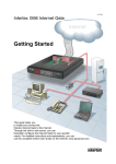
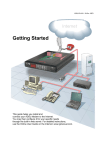
FOLLOWSPOT 2500 HTI
USER’ S MANUAL release 1.0
This manual must be considered an integral part of the projector.
BEFORE CONNECTING AND USING THE PROJECTOR, IT IS IMPORTANT TO READ CAREFULLY ALL THE
INSTRUCTIONS IN THIS MANUAL.
QUALIFIED PERSONNEL ONLY, IN COMPLIANCE WITH ALL THE SECURITY LAWS, CAN DO THE
INSTALLATION, THE MAINTENANCE AND THE UTILISATION OF THIS PROJECTOR.
BEFORE CONNECTING THE PROJECTOR, MAKE SURE THAT THE FREQUENCY AND THE VOLTAGE
VALUES ARE SUITABLE AS SPECIFIED ON THE PROJECTOR.
DISCONNECT MAINS POWER SUPPLY BEFORE ANY OPERATIONS.
FOR ANY DOUBT, CONTACT YOUR SUPPLIER OR SEND AN E-MAIL TO:
[email protected]
INDEX
GENERAL DESCRIPTION --------------------------------------------------------------------------- 2
START – UP PROCEDURES ------------------------------------------------------------------------ 5
LAMP INSTALLATION -------------------------------------------------------------------------------- 7
OPTICAL SYSTEM ------------------------------------------------------------------------------------ 8
BEAM ANGLE ------------------------------------------------------------------------------------------- 9
MAINTENANCE ----------------------------------------------------------------------------------------- 10
WARRANTY --------------------------------------------------------------------------------------------- 11
SPARE PARTS ------------------------------------------------------------------------------------------ 12
1
GENERAL DESCRIPTION
PARTS OF THE PROJECTOR
As shown in the figure, the FOLLOWSPOT 2500 HTI is made up of the following parts:
1. Upper lid (re-lamping or maintenance)
2. Handle
3. Knob adjustable projector
4. Bracket (d. 12mm)
5. Adjustable zoom
6. Adjustable focusing
7. Front opening
8. Rear panel
9. Ballast connection cable (2m)
10. 6 pin connector
11. Colours
12. Iris
13. CTO filter correction
14. FROST filter
15. Adjustable dimmer / black out
16. 6 pin panel connector
17. Cable 3G2.5 not terminated
18. Four plastic feet
19. Forced air exit
TECHNICAL FEATURES AND DIMENSIONS
Voltage rating
Frequency
Maximum surface
temperature
Main mount via # 1 screw
Projector measure
Ballast measure
230 V
50 Hz
Rated current
Absorbed power
Maximum room
temperature
Operating
Weight of the projector
Ballast weight
70° C
M12
1375x580x430mm
350X254X525mm
2
14.7 A
3050 W
40° C
+/- 45°
34 kg
32 kg
REAR PANEL
As shown in the figure, the following elements can be seen on the rear panel:
1.
2.
3.
4.
Projector work hour counter
ON – OFF lamp switch
Serial number and other characteristic
Main ballast supply cable
ADJUSTMENT OF PROJECTOR BODY ANGLE
As shown in the figure, to control manually the movement of the vertical axis, it’s sufficient to loosen the knobs of
the bracket. Thanks to the innovative reinforced bracket with teflon coated disks, you can avoid hard adjustments
and obtain smooth movement and perfect stability of the product, even in case of “release”. The vertical movement
is +/- 45° compared to the assembly position of the bracket.
WORKING POSITION
The FOLLOWSPOT 2500 HTI can work in all positions.
3
MECHANICAL SAFETY GUARDS
A bipolar cut-off switch is located between the lamp compartment and the cooling unit. This safety switch cuts off
the power to the projector if the top lid is opened.
Always ensure that the power to the projector is disconnected before opening the projector or
commencing any maintenance work.
NOISE LEVEL
After the projector has been powered up and the initial configuration takes place, the noise produced by the
projector is primarily due to its cooling system. The noise level is much lower than the limit of 70 db as permitted by
law.
PACKING
The projector is shipped and delivered in a cardboard box made of KRAFT cardboard and semi-chemical additivefree paper, in compliance with BSFV Class 3 standards for waste disposal.
The projector is completely assembled, placed in the box inside a polyethylene bag and held firmly in place with
polyurethane foam packing material. The box is stapled shut.
Even though the packing provides complete protection from rain, it must not be exposed to inclement weather or
humidity.
No more than three identical boxes can be stacked one on top of the other.
STORAGE
The projector, in its original packing, must be kept in covered, dry areas with a temperature between –10°C and
+50°C.
HANDLING
The projector, with or without packing, must be handled with care.
Lifting and handling must be carried out with special equipment. Do not expose the projector, with or without its
packing, to brusque accelerated or decelerated movements, knocks, dragging, or other stress caused by
unsuitable handling.
IMPORTANT
The projector in its packing can be seriously damaged if it falls or suffers a blow during transportation.
HANDLE WITH CARE!
4
START-UP PROCEDURES
POSITIONING AND INSTALLATION
Follow these steps to open the package and install the projector in its working position:
• Place the projector near the place where it will be installed.
• Open the package and remove the anchoring elements, accessories, and User manual.
• Carefully read the instructions in the manual.
• Arrange tripod or stand or any other adequate support.
• In case of tripod or stand, position the projector on an horizontal plane and mount on the rotating pivot in
the middle of the adjustable anchoring bracket.
• Using an adequate lifting equipment, complete the mounting on the stand or on any other suitable support.
• Tighten the M12 bolts and insert a device to prevent them from accidentally loosening.
• Make sure all adjustable parts are locked firmly in place in the desired position.
CAUTION
You must verify the stability of the anchoring elements when the projector is in working condition. In
compliance with the laws in force, the anchoring support must hold a load of minimum 80kg. Screws,
hooks, and hardware must be inserted correctly and installed to prevent from accidentally loosening.
IMPORTANT
The cooling aperture of the projector must be at, at least, 30cm from any objects that can obstruct it.
ADMISSIBLE ENVIRONMENTAL CONDITIONS
The projector was engineered and produced to function in covered dry areas with an air temperature ranging
between 0° and 40° C, and with a humidity level between 30 and 90%.
Sharp changes in room temperature may generate condensation inside the projector which can harm the projector.
Therefore, switch on the projector only after it has undergone a period of gradual adaptation to the room
temperature.
5
POWER SUPPLY
Use the cable provided inside the special junction box. The power line must be protected by a differential MGT
breaker, while metal parts, that might be electrically charged through the projector must be grounded. This
FOLLOWSPOT absorbs 3050W at 230V (LAMP ON). Make sure the projector does not pull the cable in all different
working positions, and that sources of heat are not placed in the vicinity.
Connect the fixture to the mains with the enclosed power cord and plug. See the table for the colours of the
connection-cable.
When in doubt, consult a qualified electrician.
DANGER
Be careful with your operations. With a high voltage you can suffer a dangerous electric shock when
touching the wires! Inside the projector, the ignitor circuit have very high voltage, over 5Kv.
WARNING
The User must ensure that the power supply is provided with a highly sensitive differential circuit breaker
30m/A to protect the projector from indirect contacts, and that the grounding system PE is working
properly.
WARNING
Don’t power the projector with a dimmer circuit
6
LAMP INSTALLATION
•
•
•
•
Switch off projector and disconnect power!
Loosen the hexagon screws on the frontal panel and on the rear panel (2+2).
Remove the upper lid of the projector, insert your hand inside the frontal hole to help you remove the lid.
Remove the lamp from the packing and carefully read the manufacturer’s instructions.
LAMP OSRAM HTI 2500W/SE G22. Insert the lamp into the socket and the cables into the ceramic connector,
regulate the lamp, if necessary. The lamp holder is aligned at the factory.
Replace the top lid (4 screws) and firmly tight the screws.
Loosen the hexagon screws
Remove the upper lid
Lamp OSRAM: HTI 2500W Single Ended G22
7
OPTICAL SYSTEM
The FOLLOWSPOT 2500 HTI is provided with a high-efficiency optical system is comprising up of a mirror, a
double optic condenser and two frontal lenses. This system allows the FOLLOWSPOT 2500 to project an
extremely powerful and homogenous light beam
LENS ADJUSTMENT
The FOLLOWSPOT 2500 has a lens system that lets you create beams of different sizes. It has a manual zoom
with manual focusing.
With projector ON, in order to obtain the desired beam aperture, it is sufficient to act on the control knob, visible on
the picture and located on the side of the projector body.
See the drawing.
The projector has a standard zoom between 9.2° and 5.8°, with adjustable focusing from 3m to infinity.
To project very far with a smaller beam angle, it is necessary to take away the focus lens. The beam angle will be
4,6° and the light output is at its maximum power.
In this case the zoom lens will do the function of the focus lens, from approx 40m to infinity.
DIMMER / BLACK-OUT
The followspot 2500W has a dimmer and black-out system.
It is sufficient to turn the dimmer / black-out control knob to get from 100% light to black out.
Without the focus lens, the control knob is used for the black out function.
GOBOS HOLDER
To insert the gobo holder into the projector, follow these steps:
•
Choose the pattern you want, standard M-size, metal or glass gobos.
•
Fix the pattern on gobo holder, use the 3 screws given.
•
Remove the lid of gobo holder slot, before the iris lever.
•
Insert the gobo holder in its seat.
8
BEAM ANGLE
The diagrams show the beam angle and the light output
This FOLLOWSPOT is ideal for distances from 30 to 100mt.
The projector was tested with new and regulated lamp.
The characteristics in the table are real, not finctional.
Foot candles = Lux * 0,0929
9
MAINTENANCE
Safety guards, lenses and filters must be replaced if they are visibly damaged to the point that they become
ineffective (i.e.: if they have deep slashes or cuts)..
The lamp must be replaced if damaged, cracked or deformed by the heat
PLANNED MAINTENANCE
OPERATION
FREQUENCY RESPONSIBLE
600 hours
User
Optical efficiency test
600
hours
"
"
Lamp replacement
Quarterly
"
"
Surface temperature test
Every
two
months
"
"
Cleaning
Testing for safety breaker circuit
Monthly
"
"
on general electric system
Check damage to cables due to
Once a year
mobile use projector
General service check of projector Every two years
"
"
ACTION
M1
M2
M3
M4
Check life-saving safety device by
pressing its "T" bottom
Replace cable if damage
Authorized technician
CAUTION
Always use original spare parts to ensure safe and proper functioning of the projector.
ATTENTION
Do not make changes to the projector. A modified projector
Requires a new CE marking
M1 OPTICAL EFFICIENCY TEST
Use the controller to focus the beam on a flat surface, keeping the Iris and Dimmer at 100%. If the spot is not
homogeneous, follow these steps:
• Turn clockwise or counter clockwise to optimise the horizontal position of the lamp compared to the optical
system. (3 lateral screws)
M2 LAMP REPLACEMENT
The lamp must be replaced with the same type of lamp and according to the same frequency. A less efficient lamp
jeopardizes projector performance. Replace the lamp as follows:
• When the projector is cold, turn off the ON/OFF SWITCH to cut the electricity and open the top lid to
access the lamp compartment.
• Remove the lamp from the lamp holder.
• Remove the new lamp from its packing and carefully read the manufacturer’s instructions
• Inserting new lamp in its lamp holder
• Block the wire contact firmly to avoid low efficiency connection.
10
M3 SURFACE TEMPERATURE TEST
Before you check the temperature, make sure the projector is in its full operating mode (wait about 20 minutes after
switching on the projector). Use a contact probe to measure the surface temperature on the projector’s metal case
and determine the hottest area.. The temperature must be less than 70° C. Otherwise, check the cooling system.
M4 CLEANING
Cleaning must be carried out when the projector is cool disconnected from the power supply with the general
power switch turned off, and the ON/OFF switch on the rear panel switched OFF.
FREQUENCY
It is recommended to clean the projector every two months to ensure efficiency and performance. If the projector is
used in particularly smoky or dusty areas, clean the projector more frequently.
Cleaning Procedures
1 Open the top lid by unscrewing the knob and remove it from its seat.
2 Use a low power comprised air to remove dust.
3 Use a soft cloth (non fabric) and pH neutral (pH7 ) liquid detergent to clean mirror and lens surface. Make sure
you remove all residual traces. Never touch the lamp directly with your hands or materials that can leave greasy
traces.
4 Follow the same steps to clean the other internal parts of the projector.
5 Make sure the cleaning procedure did not damage any internal part or modified their correct position
6 Replace the top lid and firmly tight the knob.
If the projector is operated in ordinary working conditions and the user follows the planned maintenance operations
established by the Manufacturer, it should last for years.
When the projector is discarded, it must be disposed of according to recycling laws.
WARRANTY
FOLLOWSPOT 2500 HTI is guaranteed against any manufacturing defects or material flaws. If defects or
breakdowns occur during the warranty period, the manufacturer, directly or through its agents. After inspection and
according to its own unquestionable judgment, the manufacturer will repair or replace the defective part.
No goods can be returned, for any reason without previous authorisation from the manifactured, and the transport
charges, to and from LAMPO are at the cost of the client.
The warranty is not valid in the following cases:
1 If the projector was used improperly or with negligence, or if it was damaged and repaired and/or modified to the
point of jeopardizing safe functioning.
2 If the projector is used in conditions other that those specified in this manual.
3 If non-original spare parts are used.
4 All malfunctioning and breakdowns caused by acts of God, negligence, and improper use, and parts subject to
wear are not covered by the warranty.
11
SPARE PARTS
When ordering spare parts for the projector remember to mention the model and serial number which can be found
on the plate at the rear of the projector.
Call your area dealer or feel free to contact the manufacturer for any additional assistance.
SPARE PART LIST
CODE
DESCRIPTION
LENSES ORDER FROM REAR TO FRONT
PAR35
Spherical mirror d.68mm
LEN68
Aspheric lens d.68mm
LEN14
Fields lens d.100mm
LEN06
Focusing lens d.150mm
LEN60
Frontal lens d.200mm
PL07
DIC27/R
DIC27/VE
DIC27/B
DIC27/V
DIC27/G
DIC27/FR
DIC27/3200
AL06
OB13
EA00012
INT13
INT22
MOR03
VEN02
MO00017
EE00130
EE00145
AB00143
EA00011
IR00006
VM00005
VOL05
G22 socket
Dichroic filter RED d.78mm
Dichroic filter GREEN d.78mm
Dichroic filter DARK BLUE d.78mm
Dichroic filter VIOLET d.78mm
Dichroic filter YELLOW d.78mm
Filter SOFT BEAM d.78mm
Filter 3200°K d.78mm
N°1 ballast 50/60Hz (1/2 ballast)
Capacitor 80microF (1/3 capacitor)
Power supply filter 25A
Switch 2x25A MGT C
Lamp switch 2P
Ceramic buckler
120mm FAN 230V (for ballast)
Projector big special FAN, with capacitor
PCB distribution (fastom)
PCB power supply (buckler)
Lamp ignitor MSR-HTI 2500W
Work counter hour (50/60Hz specified with order)
Only iris (professional iris)
Plastic handle (big)
Lateral plastic handle
ACCESSORIES
CODE
SP20
SP07
SP12
LP102
DESCRIPTION
Followspot stand, up to 1.6m
Fixed pivot
Rotating pivot
Flight case (on request)
Lamp OSRAM 2500W HTI
On request are available spare parts list and diagrams (send e-mail please)
12