1
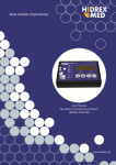
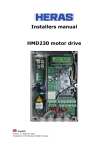
erbotherm 1100 P
User manual
07.1998
1
2
ERBE erbotherm 1100 P
Operating Instructions
3
Manual part number: 80120-041
erbotherm 1100 P No. 10204-020
All rights reserved. No part of this document may be translated, stored in information retrieval systems, or
transmitted in any form or by any means - electronic or mechanical, including photocopying, recording or
otherwise - without the written permission of ERBE Elektromedizin.
Printed by: ERBE Elektromedizin
Printed in Germany
Copyright © ERBE Elektromedizin GmbH, Tübingen 1998
4
5
6
Contents
Chapter
Title ................................................................................................... Page
1
General information .................................................................................9
2
Commissioning ......................................................................................14
3
Treatment ...............................................................................................18
4
What to do when problems occur ..........................................................21
5
Summary of operations ..........................................................................22
6
Technical data ........................................................................................23
7
8
CHAPTER 1
General information
Application of the high frequency heat therapy
The 1100 P is an appliance for high frequency heat therapy that operates at
the well proved frequency of 27.12 MHz (wave length 11 m). It enables the
classical therapy in condenser and electromagnetic coil fields in both the
continuous and the modern pulsed modes of operation and, therefore, it is
suited for all heat therapy treatments in clinic as well as practice.
The use of high frequency energy for heat therapy has the advantage of larger
penetration depth in contrast to the conventional methods, such as hotpacks,
baths, infrared light and heat pillows, and even to the microwave.
The heat endogenically generated by this appliance induces a whole range of
physiological processes which, for example, spasmodically influence the
muscular system, tendons and other connective tissue structures, increase
the cell metabolism and rate of enzyme reaction and improve the blood
circulation in the area under treatment.
As the high frequency energy can be applied in short but high energy shocks
(pulsed mode) the penetration depth can be increased further, particularly
the positive effect on the blood circulation, while the thermosensitive skin
hardly feels the heat.
High frequency heat therapy can be applied in a wide field. It is particularly
suited for all rheumatic ailments of the joints and muscular system,
inflammatory ailments of respiratory organs, kidneys and urinary tracts and
all ailments caused by poor blood circulation.
Please, observe the table of application.
For acute conditions the pulsed mode of operation offers advantages.
Structure of the appliance
The appliance is trolley-mounted with castors, two of which are fitted with
brakes that can be actuated fort the required stability.
The top part of the appliance is designed as control panel. On the panel,
covered by an easily to be cleaned and, thus, user-friendly protective foil,
there are arranged all the necessary control and display elements.
By means of dosage knob (17) the output power is adjusted via an angular
momentum generator. Power switch (1) (ON/OFF) is provided on the left
side of the panel. At the rear of the appliance there are the screw holes for
attaching the arms (36), the sockets for connecting the cables of the condenser
9
(31) and coil (30) applicators and the connection part of the detachable mains
supply cable (33) including fuses. The ripcord (34) for the patient emergencyOFF switch passes through a bushing mounted in the arm fastening area so
that it can be pulled from all directions.
Arms
By means of clasp (27) the arms are mounted at the rear of the appliance (35).
Condenser applicators according to ,,Schliephake” are used in pairs, therefore,
both arms are necessary. Only one arm is required for using coil applicators
as only one applicator is used at a time. In the last case, both arms can remain
fixed to the appliance and be equipped with different applicator types to enable
a quick change of applicators as the case demands.
Due to its stable structure and five hin ges, the arm can safely fix the applicators
in widely differing treatment positions. As the arms are made of high quality
flame-resistant plastic material they can be used to guide and hold the
applicator cables for avoiding inadvertent contact between patient and cable.
Apart from the horizontal swing of the aim and hinge (20) in the applicator
holder(19), all hinges can be adjusted by the user as the treatment demands.
With lock knob (26) for the lower rotating hinge (25) the whole arm is fixed,
also with the arm maximally extended, depending on the different weights of
the applicators. With the other main hinges (21; 23) the length and height,
which are mutually dependent, can be varied after the appropriate knobs
have been loosened. In doing, it is practical to support the arm at an upper
hinge (20) or (21).
Condenser (Schliephake) and coil applicators are inserted into the aperture
of applicator holder (19) with their shafts until the slide (18) catches, which
is clearly noticeable.
With using coil applicators, the connection cable should also be fed first
through the aperture. For removing the applicator push back slide (18) and
draw the applicator out of the holder.
The central joint of the arm (joint between the middle and lower arms - item
23 in the figure) is adjusted to a basic braking force by the manufacturer.
After long-term application it can be necessary to readjust the basic braking
force due to abrasion of plastic parts and brake disks. For this purpose, remove
the blue cover by means of a screwdriver and tighten the hexagon bolt below
(cf. figure) by about a half revolution.
At the joint (at the appliance - item 25), braking the horizontal motion of the
arm, the readjustment can be done by means of the slotted nut below it (cf.
figure).
10
Applicators and applicator Cables
Coil as well as condenser applicators can be used with the 1100 P.
Condenser applicators (distance
applicators according to
,,Schliephake”)
Three pairs of different diameters are available. Characteristic for applicators
used with the 1100 P is the optimum ratio of the fixed electrode-to skin distance
(measured from the outside of the applicator casing to the inner electrode plate)
and the corresponding electrode area. This results in low-loss transmission of
the high frequency energy from the generator via applicator to the patient.
Condenser applicators, elastic
These applicators are available in two different-sized pairs. The permanently
attached, highly flexible cable ensures maximum flexibility at the point of
applicator connection and high adaptability to bent or curved parts of the
patient’s body. The optimum distance between applicator and skin is achieved
with thick felt spacers that have to be placed in a cloth bag together with the
applicator. Velcro fastener or rubber bands can be used for fastening this
applicator arrangement.
Coil applicators
Three different sizes of different effective surfaces can be used for adjusting
to size and volume of the different treatment areas.
This applicator type uses the high frequency magnetic field of the coil of an
electric resonant circuit Yartherapy.To support this effect as efficiently and
focusedly as possible all coil applicators of the 1100 P are electrically shielded
and connected to the appliance with shielded cables, too. This means, electric
disturbances of nearby appliances (current stimulators, etc.) are avoided to a
great extend.
Applicator connection cables
Highly flexible, low-loss special cables (29) are used to connect the condenser
applicators.
A hooked connector is provided to avoid damaging kink strains in the
applicator connection area. Electrically superior flame-resistant silicone
insulating materials have been applied to avoid cable defects also when used
incorrectly (e. g. in case the cables touch to each other).
WARNING
To avoid any unwanted and inadmissible heat application to the patient he/
she should not touch a cable. Therefore, abundant cable length should be fed
through the lower arm part (24) to secure it.
Cleaning and disinfecting
Before cleaning or disinfecting the appliance must be switched off and the
mains plug disconnected.
For cleaning and disinfecting the appliance and accessories (except for the
felt spacers, of course) we recommend commercially available surface
disinfectants to be used according to their instructions for use.
For reasons of material acceptance, only surface disinfectants basing on agents
like aldehydes, alcohol’s or ammonium compounds are suitable or wipe and
spray disinfection. They are to be used according to their instructions for use
and duration of action.
11
Examples:
Hexaquart
Bazillotox
Buratron 10F
Dismozon
Frekanol
Nucosept o.F
Ultrasol
Hansa-Sept
Lysoform
Incidur
Melsitt
For users in the Federal Republic of Germany we basically recommend the
use of disinfectants published in the DGHM (Deutsche Gesellschaft für Hygiene und Mikrobiologie) list. The DGHM list contains also the basic agent
of the corresponding disinfectant.
For reasons of possible material damage, also products basing on halogensplitting compounds, strong organic acids and oxygen-splitting compounds,
solvents, benzene and similar agents are not suitable.
WARNING
While cleaning and disinfecting it is to be observed that no fluid penetrates
into the appliance accessories. Sockets that have become wet are to be
thoroughly dried before any further use!
TÜV tests, safety
WARNING
This electromedical device shall only be applied by people which ensure the
correct handling due to their special training or knowledge and practical
experience and which have been trained for the correct operation on the basis
of the present operating instructions. The training shall be only performed by
people which are suited for instructing the handling of the device due to their
knowledge and practical experience. As the manufacturer of this appliance
we only consider ourselves responsible for the technical safety qualities if
the 1100 P is used according to the present operating instructions.
Any repair - including opening the unit - shall only be performed by our staff
or after-sales service shops especially authorized by us. In the interest of
functional safety of the appliance we recommend at least one annual safety
check by the after-sales service.
Prior to the application, the appliance has to be checked by the user for
convincing that its function and condition are correct. This includes regular
inspections of all cables and lines for possible insulation defects.
In the result of the safety tests performed according to DIN IEC 601 and
VDE 0750 the TÜV-GS sign and the BZT Registration Number of the Bundesamt für Post und Telekommunikation were granted to the 1100 P. With
the card attached, please, make the application for the operation license.
WARNING
According to its designation the appliance generates high frequency electric
and magnetic fields that penetrate even walls, ceilings and floors. It cannot
be excluded that components of these fields exists in the vicinity of the
appliance. Sensitive electronic instruments which are arranged in the
immediate vicinity of the 1100 P can be disturbed. This danger largely depends
on the distance between the devices. Therefore, during the installation of the
12
appliance, it should be taken into consideration that the distance to other
sensitive devices should exceed 5 m, if possible, and the applicators are not
directed to sensitive devices, as for instance current stimulators.
This problem can be completely eliminated when the appliance is
accommodated in a shielded room, that means in a Faraday cage. (A Faraday
cage enclosed by a metal housing or grid prevents the penetration of electric
fields.) Often, a sufficient interference suppression is obtained by only
connecting the devices to isolated mains circuits or using screening curtains
(special curtains between the treatment cabins). Supplier is:
nsp Sicherheitsprodukte GmbH
Hauptstr.17
86695 Nordendorf
Germany
Phone: 049-82 73-10 31.
To stay within the limits given by DIN 0848, Part 2, we recommend that the
operators and other persons keep a distance of at least 2 meters to the
applicators and cables. In case of doubt, it is recommended to measure the
field strength. Pregnant women should not operate the appliance.
13
CHAPTER 2
Commissioning
WARNING
The appliance is not designed to be operated in environments in which there
is danger of explosion. If used in anesthesia rooms where inflammable
narcotics are simultaneously used an explosion cannot be ruled out.
Mains connection
The standard appliance is to be connected to a mains voltage of 230 V ± 15
%, 50/60 Hz. However, a special version is also available for the connection
to 115 V ± 15 %, 50/60 Hz. (The actual value is shown on the rating plate at
the rear of the unit).
Before connecting to the supply mains check the conformity of the voltage
values of the available mains and appliance. The appliance is to be only
connected to a properly installed earthed socket outlet by means of the shielded
mains connecting cable included in the basic accessories.
For the fuse to be applied with the 230-V mains we recommend a slowacting 10-A one.
Switching on
Switch on the power with switch (1) on the left of the operating panel. Now,
the appliance is in the stand-by mode of operation. The indicators ,,Dosage”
(15) and ,Treatment time” (14) are lit. Further settings are to be made on the
keyboard (cf. figure).
Mode operation
Select the mode of operation with the keys (3), (4) and (8) in the “MOGE”
field. Pressing key (3) turns the appliance to the continuous mode of operation.
Different pulsed modes of operation can be selected by pressing key (4) or (5).
They differ in pulse width and pulse repetition frequency. The chosen mode
is shown by the indicator light in the corresponding key marked by the symbol.
The mode of operation can only be selected when the dosage display (15)
shows „0“.
Choice of the applicator
The choice of the appropriate applicator is made according to area and volume
of the body parts to be treated and according to preferring the coil or condenser
field application.
14
By pressing key (6), (7), (8) or (9), (10), (11) in the „APPLICATOR” key
pad the dosage (output power) is limited according to the selected applicator
so that an unintended overheating of the tissues is avoided.
The following keys are assigned to the corresponding applicators:
K ey
Applicator
6
C oi l appli cator, 50 cm2
7
C oi l appli cator,150 cm2
8
Tri plode 500 cm²
9
C ondenser appli cator, di ameter 4,2 cm and
condenser appli cator elasti c, 8x14 cm
10
C ondenser appli cator, di ameter 8,5 cm and
condenser appli cator elasti c, 12x18 cm
11
C ondenser appli cator di ameter 13 cm
Sy mbol
As mentioned above, any programming is only possible with the dosage
display (15) showing ,,0".
Connection of the applicator
Applicators are electrically connected to the sockets (30) or (31).
The coax cable of the coil applicator is connected to socket (30). In doing,
the threaded cap of the plug is to be completely screwed onto the socket.
The cable pairs of the condenser applicators are to be connected to socket
pair (31).
Insert the plug pins into the socket up to the stop!
Please, observe that in any case only the connectors of the condenser applicator
cables or the connectors of the coil applicator cable are plugged into sockets
(30) or (31), respectively. Never connect all three cables simultaneously.
Treatment time
Set the treatment time with keys (12), increasing, or (13), decreasing. The
actual value is shown on display(14). Pressing the keys for a short time will
set the time in 1 -minute intervals, pressing them continuously will set the
time in 5-minute intervals. When both keys are simultaneously pressed the
time is reset to,,0".The maximum time that can be set is 30 minutes.
Changing the time during the treatment is also possible. After the clock is set
it starts automatically when dosage knob (1n is shortly turned to the right,
display “Ab” fades and the selected treatment time appears again on display
(14). During the treatment the remaining time is shown on display (14). The
end oft he programmed time is acoustically signalled. This signal is constantly
repeated every minute until dosage knob (17) is shortly turned to the left.
15
Setting the dosage
After the settings have been completed the dosage can be selected with
dosage knob (17). An incomplete setting results in the error message ,,FE 0"
appearing on ,,Dosage“ display (15). Cancel the error message by turning
the dosage knob to the left and make up the missing setting. Keep in mind
that the dosage is to be only selected with the applicator(s) correctly adjusted
to the patient’s body and connected to the appliance. Dosage knob (17) has
no right and left stops. Turning to the right increases the dosage in dependence
on the dosage range in the following steps per lock point:
Up to 30 W in 3-W steps
From 30 W to 90 W in 5-W steps
From 90 W to 200 W in 10-Wsteps
This applies for both the continuous and pulsed modes of operation.
In order the appliance can deliver the high frequency dosage level selected
with dosage knob (17) it is automatically tuned to the patient data after a
short right turning of dosage knob (17).
During this process the tuning symbol “Ab” appears on the,7reatmenttime”
display (14) instead of the treatment time, and no further operator settings
are accepted by the unit in this time period. Termination is only possible by
pressing ,,RESET’ key (2). The effect of the tuning process is shown on the
display „Coupling with the patient” (16). The best RF power transfer to the
patient is achieved when display(16) is totally lit. As the tuning takes place
with minimum dosage the position of the applicator(s) to the patient can be
changed during this process to enhance the dosage transfer. After the tuning
process is terminated the treatment time is shown on display (14) again and,
starting at this moment, the actual output power (dosage) is shown on display
(15). The tuning process can be repeated by turning dosage knob (17) to the
left up to ,,0" and subsequently turning it to the right again. Now, the dosage
can be increased to the desired level by turning dosage knob(16) further to
the right. First, the desired dosage level is shown on display (15) and at the
end of the tuning process it is changed to the active value. Then, this dosage
level is stored and automatically readjusted by the appliance in case the patient
moves or the mains voltage fluctuates. Thus, any accidental increase of the
dosage due to patient movements is safely avoided, too.
Switching off (emergency disconnection by the patient)
The high frequency power or the entire appliance can be switched off as
follows:
a) Turn off the power switch (1). (Entire appliance).
b) Press the RESET key (2). (The appliance is set to the stand-by mode as
after switching on the power switch.)
c) Simultaneously press the time keys (12) and (13). (The mode of operation
and applicator type remain stored.)
16
d) Turn dosage knob (17) to the left until ,,0" appears on display (18). (The
mode of operation, applicator type and remaining treatment time are kept
stored.)
e) End of the adjusted treatment time. (The mode of operation and applicator
type remain stored. Cancel the acoustic signal by turning the dosage knob to
the left.)
f) Emergency off by the patient by using the ripcord (84).Any use of the
ripcord is indicated by an intermittent ,,beep” sound and ,,FEC” appearing
on display (15). Switching back to the stand-by mode is done by pressing the
RESET key (2).
Switching off by the safety circuit
After switching on the appliance and during the operation the ,,microcontroller”, provided for the entire control functions of the unit, automatically
performs many control sequences to ensure the safety of patient and appliance.
In doing, any detected error is shown on the ,,Dosage” display (15) and the
output power (dosage), if applying, is immediately switched off. This error
condition is additionally indicated by an intermittent acoustic signal.
The error messages are indicated by the symbols:
FE 1, FE 2, FE 4, FE 6, FE 6, FE 7 FE 9, FE a, FE b, FEC.
If anyone of these error messages is displayed the appliance must be switched
off and the after-sales service informed.
The FE 0 message means the parameter settings are incomplete. This condition
is to be eliminated. No acoustic signal follows this error message.
17
CHAPTER 3
Treatment
Preparation of the patient
To ensure an optimum therapy the patients and especially the parts of their
bodies that are to be treated should be completely relaxed. A comfortable
lying or seating position is the best condition for this.
Patients shall never be treated on metal chairs or beds.
Hearing aids, watches, rings, chains, bracelets and other metal objects are to
be removed for safety reasons before the treatment is started. This also applies
to persons close to the appliance or applicators and cables, e. g. the operating
staff.
The parts of the body involved should be treated in unclothed condition.
Especially clothes made of synthetic materials are to be removed because
they absorb moisture insufficiently; gathering moisture on the skin (skin folds)
can local overheating.
Before starting the treatment the ripcord is to be handed to the patient so that
he/she can switch off the appliance when he/she feels nausea or unbearable
heat sensation.
Implants
High frequency heat therapy is contra-indicated for patients with pacemakers.
Body parts with metal insertions (e. g. bone-fixation nails, grenade splinters,
etc.) shall not be treated.
Pregnant women, endangered organs
Treatment of pregnant women is contra-indicated in the abdominal area.
Other contra-indications are growing-grooves, tumors, tuberculosis, disturbed
arterial blood circulation of stages lll and lV, varicose veins, general tendency
to bleeding.
The doses must be carefully selected for organs with low vascularization and
low blood circulation (e. g. eyes, testicles)!
Heat effect of the applicators
The evaluation of the heat effect of applicators on the basis of the subjective
heat sensation by the patient is strongly influenced by a number of factors, e. g.
18
the thickness of fat layers, treatment through clothes or bandages, blood
circulation, temperature of the skin, etc.
Therefore, the following subclauses generally explain the operation of the
applicators used with the 1100 P. The heat effect of the electrodes differs
fundamentally between the inductive and capacitive method of application.
Capacitive method of application
With the capacitive method of application the transformation of energy into
heat mainly takes place in tissues with low blood circulation (e. g. fat,
connective tissues). Thus, the greater part of heat is generated in areas near
the surface (upper-skin fat tissue) so that not only the transformed energy but
also the distance between applicator and skin is important for the subjective
sensation of heat.
Depending on the size of the applicator the condenser applicators of the 1100
P are designed with an optimum electrode-to-skin distance. On this way,
every good distribution of heat in the tissue is ensured by the choice of the
appropriate applicator size.
Inductive method of application
The high frequency magnetic field of a coil applicator generates eddy currents
that are transformed in the tissue. These currents increase with the electric
conductivity of the corresponding tissue region (tissues with good blood
circulation, e, g. muscle tissue and inner organs).
To reach these deeper tissues the coil applicators of the 1100 P are provided
with an electrostatic shielding that prevents the technically unavoidable electric
field of the coil applicator from effecting the upper-skin fat tissue and its
heating, Therefore, the feeling of heat is basically delayed and it is
recommended to start the treatment with a dosage level below the desired
one and increase then guided by the patients heat sensation in the treated area
The dosage and treatment time values given in the application table should
be observed.
WARNING
During all the treatment time, the patient must contact the triplode!
If the patient is excessively heated up, do not change the body-triplode contact
but decrease the output power or the patient turns of the 1100 P by pulling the
ripcord.
Intermediate checks are to be performed, if required. In doing, observe the
actual dosage shown on display (15) and readjust, if necessary, due to the
automatic tuning, to obtain reproducible results within a treatment series.
An excessive output power (dosage) and missing intermediate inspections
by the therapist often result in mismatching in the practice because the patient
often does not switch off the 1100 P by means of ripcord and emergency-off
switch but changes his/her position so that the necessary body-triplode contact
does not exist. This is indicated by the luminous band indicator in the way
that not 8 to 10 LED’s as required but only a few are lit. Due to this, the
19
adjusted electric output power is not converted into heat only in the patient
but also in the triplode itself which possibly can damage the last.
For safety reasons, the side wings of the triplode are equipped with small
ventilators starting forced cooling with medium and higher output powers.
Unfortunately we must point out that failures due to erroneous operation are
not covered by the claims of warranty and may be very expensive.
The good matching between patient and triplode by body contact is indicated
by the fact that 8 to 10 LED’s of the luminous band indicator are lit, i. e. the
optimum of about 80 to 100 per cent oft he adjusted output power is converted
into heat in deeper tissues of the patient.
In special applications, e. g. both knees at the same time, where the maximum
matching can be obtained with only about five LED’s (50 %) are lit the output
power shall only be adjusted to 50 percent of the maximum one, i. e. 100 W.
The following rule applies:
The value of the adjusted dosage shall not exceed the number of the illuminated
LED’s of the luminous band indicator times the factor 20!
With too weak coupling, higher output powers (dosages) can result in heating
up the triplode and possible damage it!
Loadability of the applicators
The loadability of the individual applicators depends on their surface.
Overheating of the applicators, in particular the coil applicators, on the one
hand and an unbearable heating of the tissue on the other hand is avoided as
the appliance automatically limits the output power (dosage) of the applicato
to its admissible level.
The following table shows the limited dosage values of the individual
applicator types:
When different condenser applicators are combined the smallest type of
K ey
Applicator
Limited power in Watts
6
C oi l appli cator, 50 cm2
30
7
C oi l appli cator,150 cm2
90
8
Tri plode, 500 cm²
200
9
C ondenser appli cator, di ameter 4,2 cm and
condenser appli cator elasti c, 8x14 cm
21
10
C ondenser appli cator, di ameter 8,5 cm and
condenser appli cator elasti c, 12x18 cm
80
11
C ondenser appli cator, di ameter 13 cm
200
applicator determines the maximum dosage.
Deviations are possible in dependence on the heat sensation of the patient.
20
CHAPTER 4
What to do when problems occur
Experience has shown that the most problems by far occur because of
inadvertent operating errors. Therefore, before suspecting a fault in the
appliance, please, check whether the present operating instructions have been
correctly followed.
When after switching on the appliance the displays (14) and (15) and the
indicator lamp in power switch (1) do not lit, check whether the appliance is
correctly connected to the mains socket outlet and the last one is alive. If so,
check he fuses at the mains voltage connection of the appliance (33). To do
this, lift the latch and take the ,,drawer” with the fuses out of the mains voltage
connector (33). After checking and, if required, replacing a fuse re-insert
until the latch catches.
Fuses shall only be replaced by ones of the same rating and type. If fuses
blow more frequently, please, contact our after-sales service.
If the error message ,,FE 0" appears on the ,,Dosage” display (15) when
turning the dosage knob (17) to the right check whether all parameters (mode
of operation, applicator, time) were chosen or not.
If display(16) shows only little or no coupling during the automatic tuning
process indicated by „Ab” on display (14) check whether the applicator(s)
used correspond(s) to that chosen by the actuated „APPLICATOR” key(s).
Furthermore, check whether the applicator cable connection and the applicator
seat are correct. The area to be treated should be larger than or at least as
large as the applicator surface.
Incorrect adjustment at the appliance during the treatment is acoustically
signalled. For safe operation of the appliance and, thus the safety oft he patient,
a number of control measures were programmed which in case of error result
in switching off the output power and displaying the type of error.
21
CHAPTER 5
Summary of operations
• Connect the appliance to the mains. socket outlet
• Connect the applicator(s) to the appliance
• Attach the applicator(s) to the patient
• Turn on the appliance with switch (1)
• Select the mode of operation, keys (3), (4), (5)
• Select the applicator(s), keys (6) to (11)
• Set the treatment time, keys (12), (13)
• Set the dosage knob (17)
• Electric power is applied to the output, the treatment timer starts operation.
• After the chosen treatment time has elapsed the appliance automatically
turns off and emits an intermittent acoustic signal for about 10 s. This
signal is repeated every minute until the dosage knob (17] is reset by
turning to the left (counter clockwise).
• When an error is displayed (except for FE 0) press RESET key (2) and
readjust, if required.
• The entire appliance is switched off by actuating switch (1) again.
22