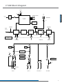
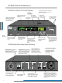
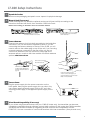
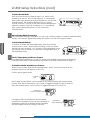
1
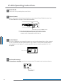
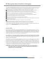
Dear Valued Customer,
Thank you for choosing Listen! All of us at Listen are dedicated to providing
you with the highest quality products available. We take great pride in their
outstanding performance because we care that you are completely
satisfied. That’s why we independently certify them to the highest quality
standards and back them with a limited lifetime guarantee. We stand ready
to answer any questions you might have during installation or in the operation
of our products. Should you experience any problems whatsoever with your
Listen products, we are ready to help you in any way we can with prompt,
efficient customer care. Because at Listen, it’s all about you! And should you
have any comments on how we might improve our products or our
service, we’re here to listen.
Here’s how to reach us:
+1.801.233.8992
+1.800.330.0891 North America
+1.801.233.8995 fax
[email protected]
www.listentech.com
Thank you and enjoy your listening experience!
Best regards,
Russell Gentner and the Listen Team
• In the few instances where repairs were needed, 99% of all clients indicated that they were happy with
repair turn-around-times and 85% of the time, clients were without their product for less than 10 days!
• Overall client satisfaction of working with Listen was rated 4.8 out of 5.
• “Please continue with your excellent attitude toward customer satisfaction. You guys are great!”
• “I’ve never had such good service from any company. Keep up the good work!”
• “You stand behind your product wonderfully.”
Assistive Listening • Language Interpretation • Soundfield • Tour Group • Conferencing
Table
Contents
Table
of of
Contents
LT-800 Table of Contents
Supplementary Information
Troubleshooting
Compliance Notice FCC Statement
Warranty
Contacting Listen
Optional Accessories
18
18
20
20
21
21
22
Listen SQ™
14
15
15
16
17
Operating Instructions
Channel Selection
Compatibility Charts
72 MHz Frequency Compatibility Chart 216 MHz Frequency Compatibility Chart Phonak Frequency Compatibility Chart Setup Instructions
6
7
10
11
12
13
13
Quick Reference
Quick Reference
Setup Instructions
Operating Instructions
Audio Control
Listen SQ™ (Super Quiet)
RF Reception Maximization Strategies
Coaxial Cable
Specifications
3
4
4
4
5
Package
Table Contents
of
Contents
Package
Contents
Package Contents
Specifications
Architectural Specifications
Specifications Block Diagram
RF Reception
Reception
RF
Channel Selection
Compatibility Charts
Information
Information
1
LT-800 Package Contents
•
•
•
•
LT-800-072 (72 MHz) or
LT-800-216 (216 MHz) or
12 VDC Power Supply
User Manual
Package
Package Contents
Contents
LT-800 Contents
Listen Part Number
LT-800-072 (72 MHz)
LT-800-216 (216 MHz)
Optional Accessories
See page 22
3
LT-800 Specifications
Architectural Specifications
Specifications
The stationary FM transmitter shall be capable of broadcasting on 57 channels. The transmitter
shall have a SNR of 80dB or greater. The output power shall be adjustable to quarter, half or
full. Channel tuning shall be capable of being locked. The device shall broadcast on both wide
and narrow band channels. The device shall have an audio frequency response of 63 Hz to
15k Hz, ± 3dB at 72 MHz, or of 63 Hz to 10k Hz, ± 3dB at 216 MHz. It shall have two mixing audio
inputs. The device shall have the following audio controls: input level, mix level and an
adjustable low pass filter. The device shall have an audio processor that is capable of
automatic gain control and limiting. The Listen LT-800 is specified.
Specification
RF
Specifications
RF Frequency Range
Number of Channels
Frequency Accuracy
Transmitter Stability
Output Power
Antenna
Antenna Connector
Compliance
System Frequency Response
System Signal to Noise Ratio
(A-Weighted)
System Distortion
LT-800-072
72.025 - 75.950 MHz
17 wide band, 40 narrow band
LT-800-216
216.025 - 216.9875 MHz
19 wide band, 38 narrow band
+/-.005% stability 32˚ to 122˚F (0˚- 50˚C)
50 PPM
80,000uV at 3 m
100mW (max allowed by FCC)
Various Antennas available
BNC
FCC Part 15, Industry Canada
FCC Part 90, Industry Canada
** All system specifications are wireless end-to-end
50 Hz - 15 kHz (±3 dB)
50 Hz - 10 kHz (±3 dB)
80 dB SQ enabled; 60 dB SQ disabled
80 dB SQ enabled; 50 dB SQ disabled
<2% total harmonic distortion (THD) at 80% deviation
Rear panel. (1) Female-XLR and ¼ in. combo connector, balanced, 0/-55 dBu (line/mic) nominal input level adjustable,
-30/+21 dBu (line/mic) maximum input level, impedance 20k/1k Ohms (line/mic), phantom power +12 VDC.
Rear panel. Two (2) Phono connectors, unbalanced, -10/+10 dBu nominal input level
Audio Input 2
adjustable, +30 dBu maximum, impedance 100k Ohms.
Audio Processing (Process)
Compression can be turned on/off. Slope internally adjustable from 1:1 to 4:1. Default 2:1
Contour
Cuts and boosts frequencies above 5 kHz
Input 1 and Input 2 Mixed Output (Rear Panel). Two (2) phono connectors, unbalanced, -10 dBu nominal output level,
Combined Audio Output (Mix)
+19 dBu maximum, impedance 10 ohm.
Headphone Output (Monitor)
Front panel. One (1) 3.5 mm stereo connector, unbalanced, adjustable output level, +7 maximum, impedance 10 Ohm.
Audio Input 1
Audio
Controls
Front Panel
Rear Panel
Internal Adjustments
Programming
Indicators
Input 1 and Input 2, Mix VU
SQ and Processing
RF Power
LCD Display
Test Tone
Power
Physical
Indicates Input 1, Input 2 and Mix audio levels. 10 segment LED’s (8 green, 2 red)
Indicated by a green LED when on (front panel)
Indicated on the LCD (low, mid, high)
Channel designation, lock status, RF Power Level, programming (front panel)
Red LED illuminates when test tone enabled
Power Supply Type
Power Supply Input
Power Supply Output
Power Supply Connector
Power Supply Compliance
In-line power supply. Listen part number LA-207 (Line cord is determined by each country’s AC power standards).
Input: 100-240 VAC, 50-60 Hz, 0.4 A
Output: 12 VDC, 1.3 A, 15.6 W
Output Connector: .02 in. (5.0 mm) OD, .01 in. (2.5 mm) ID, barrel type
UL, CE, GS, TUV
Dimensions (H x W x D)
Color
Unit Weight
Unit Weight with LA-201
Power Supply
Shipping Weight
1.75 x 8.50 x 9.13 in. (4.5 x 21.5 x 23 cm)
Dark Grey with white silk screening
2.6 lbs. (5.7 kg)
4.4 lbs. (2.0 kg)
Rack Mounting
Environmental
Power, Test Tone on/off, Channel UP/DOWN, Input levels, Mix level, Contour, Monitor volume control.
Input 1 Level (line, mic, mic-phantom power), Input 2 Level (-10/+10 dBu), RF Power (low, mid, high)
Compression ratio for audio processor
SQ on/off, Processing on/off. Channel lock
Temperature - Operation
Temperature - Storage
Humidity
5.0 lbs. (2.26 kg)
One (1) rack space height, 1/2 rack space wide. One (1) or two (2) transmitters can be mounted in one rack space.
Optional rack mount (LA-326)
-10˚C (14˚F) to +40˚C (104˚F)
-20˚C (-4˚F) to +50˚C (122˚F)
0 to 95% Relative Humidity, non condensing
Specifications are subject to change without notification
4
LT-800 Block Diagram
POWER
On
Off
Red
LED
Up
15VAC, 1A
Power Supply
CPU Module
Package
Contents
Specifications
Package
Contents
Specifications
115VAC6
0 Hz
3.5MM
Stereo
CHANNEL SELECT
In-Line
Power Supply
LA-201
(provided)
HEADPHONE
Down
Volume
Listen LCD Display
Backlighted
MIX Level
VU Meter
Top Mounted
Antenna Stud
Compression Ratio
(internal adjustment)
Remote
Antenna
Connection
Transmitter RF Board
BNC
Pre-emphasis
Processing
SQ
Companding
ANTENNA
Green
LED
Functions controlled by the CPU
Module
Low
Mid
On
High
RF POWER
Off
On
Off
SQ
Input 1 VU
Meter
Green
LED
MIX LEVEL
PROCESS
CONTOUR
Input 2 VU
Meter
Input Level
Front Panel
12VDC
Mic
Line
Mic
Phantom Pwr
Input 1 Level Select
Mic-Phantom Pwr, Mic, Line
Input 2 Level Select
+10dBu/-10dBu
+10dBu
Test Tone Button
Front Panel
-10dBu
ON
OFF
Red
LED
Female XLR-1/4"
Combo Connector
2/Tip
3/Ring
INPUT 1
Phono
Phono
400Hz
1/Sleeve
INPUT 2
MIX OUTPUT
TEST TONE
5
LT-800 Quick Reference
LT-800 Front Panel: Controls & Displays
Quick
Reference
Package
Contents
Specifications
Package
Contents
Quick
Reference
Adjust audio input levels
of Input 1 and Input 2
here. See page 11 for
more information.
Indicates
Process Mode
is active.
Indicates audio input
Indicates
level of Input 1 and
Super Quiet
Input 2.
mode is active.
Shows mixed
audio level.
Top mount antenna connection:
Remove rubber plug and screw
antenna in place.
LCD: Shows
which channel
is selected.
Monitor Port: Plug
in a headset and
adjust volume.
SQ
Power
ON / OFF
Test Tone: Activates
a tone to aid system
setup.
Mix Level: Adjust so
the Mix Level meter
occasionally lights
the red LED.
Contour: Equalization
adjustment. Turn
counter-clockwise for
voice and clockwise for
music.
Channel Select Up:
Press for 3 seconds
to lock on current
channel.
Channel Select Down:
Press for 8 seconds to
enter program mode.
See page 8 for more
information.
LT-800 Back Panel: Connections & Settings
Remote Antenna Connection:
See page 22 or the Listen
website for details on antennas
that can be attached here.
Set RF Power level here
(¼, ½, and Full). See
page 9 for guidelines
on setting power levels.
6
Mix Output: These connectors
contain a mix of Input 1 and
Input 2. They are unbalanced
phono connectors; and the
output level is -10dBu.
The Listen LA-201
power supply
connects here.
Input 2: Set switch to
match the level of your
Input 2 audio source,
not used to increase or
decrease level by +10dBu.
Input 2: Connect
unbalanced audio to these
phono connectors, input
level -10dBu or +10dBu.
Input 1: Used for balanced
connection of a microphone
or line level input. This
combination connector
accepts either XLR or ¼”
phono plugs.
Select Line, Mic or Mic+Phantom
Power. Line is balanced 0 dBu
input level, Mic is -55dBu, +12VDC
supplied in PH Power position.
If not using input 1, leave in line
position.
LT-800 Setup Instructions
1
Unpack the Product
2
Mount in Rack (if necessary)
Remove outer packaging and plastic cover. Inspect for physical damage.
If rack mounting the unit, install the optional rack mount kit (part LA-326) according to the
instructions included with the kit, then install the LT-800 in the rack.
NOTE: If rack mounting, you will need to use a rear connection antenna.
Rack Mount with dual unit installed
3
Rack Mount with single unit installed
Shown with LT-800
Connect Antenna
Package
Contents
Specifications
Setup
Instructions
Quick
Reference
Package
Contents
Setup
Instructions
Connect the antenna (not included) according to the installation
instructions. Only use an antenna supplied by Listen. If you are
connecting the antenna directly to the top of the LT-800, you will
need to remove the rubber plug on top of the unit. If you are using
a remote antenna connected to the rear of the unit, do not
connect an antenna to the top connector. See page 22 for
antenna options, or refer to the Listen website for remote antenna
options, www.listentech.com.
Coax antenna connection.
Rear of LT-800 shown.
LA-122 Remote Antenna
See RF Reception Maximization
Strategies and Coaxial Cable on
page 13.
rubber plug
LT-800 shown with top mount
antenna connected through top of
unit (part numbers LA-101, LA-106 (72
MHz) or LA-102 (216 MHz)
- +
4
Connect Power
Plug the power supply into the power connector on the
back panel, then plug the power supply into an outlet. Only
use a Listen approved power supply (The LA-207, an in-line
switching power supply, is the approved power supply for this
unit).
12 VDC 1.3 A
5
Select Phonak Compatibility (if necessary)
If you will be using Phonak receivers with your LT-800 (216 MHz only), the transmitter can become
completely compatible through software control. When switched to this mode, the LT-800 transmitter
will display the Phonak channels. By integrating Phonak channels and compatibility into the
LT-800-216, it is more convenient to use Phonak receivers with Listen transmitters. (www.phonak.com)
7
LT-800 Setup Instructions (cont.)
To Select Phonak Mode:
Press and hold down the channel select “up” button while
powering on the unit. The LCD will display a “P” momentarily
upon power up indicating that the transmitter is in the Phonak
Channel Mode. The channels displayed will now match
Phonak channels. To return to the Listen channel designations,
repeat this process. The LCD will display an “L” momentarily
upon power up indicating that you
- + are in the Listen
Channel Mode.
6
Select Channel Mode (if necessary)
Your transmitter has been shipped to you with only a limited number of channels available (Basic
Mode). If all channels (Expanded Mode) are required, use the following procedure.
To Select Expanded Mode:
Package
Contents
Specifications
Setup
Instructions
Quick
Reference
Package
Contents
Setup
Instructions
To enable or disable the Expanded Mode, press and hold the
channel select “down” button while powering on the unit. When
the Basic Mode is enabled, “L/O” (lockout) will be displayed on the
LCD display as shown below. This indicator is extinguished when in
the Expanded Mode.
7
Set SQ™ (Super Quiet) and Process Features
Your transmitter is shipped to you with SQ (super quiet) enabled and Process disabled. For
a detailed description of these features and when to use them, please refer to page 12.
To Disable or Enable SQ and Process Features:
With the unit on press and hold the channel select “Down” button for 8 seconds. The
program (PGM) icon will appear on the LCD.
Once in the program mode,
Program
icon
the SQ and Process featurs can be turned on and off by pressing the channel select
buttons. Press the channel select “Up” button to toggle between Process On and Off.
Press the channel select “Down” button to toggle between SQ On and Off.
LED lit when
Process is enabled
If the green LED is illuminated on the front panel,
that feature is enabled. Once you have enabled or
disabled the features as desired, let the transmitter
exit the program mode by waiting 5 seconds.
8
LED lit when
SQ is enabled
LT-800 Setup Instructions (cont.)
8
9
Set RF Power
Set the RF POWER switch on the back of the unit
to Full, 1/2 or 1/4 (Level is indicated on the LCD
display). The amount of transmitted RF power that
you will need depends on your application. If you
are operating multiple transmitters in the same
environment, it is best to set the transmitters
output power to its lowest level to reduce the
possibility of interference.
Full
power
12 VDC 1.3 A
1/2
power
Back of LT-800 unit
1/4
power
Connect Audio Inputs
Package
Contents
Specifications
Setup
Instructions
Quick
Reference
Package
Contents
Setup
Instructions
The LT-800 has two audio input options: Input 1 and Input 2. Input 1 is a balanced connection using
either an XLR or 1/4” phono connector. Input 2 has two unbalanced mixing phono connectors.
Use Input 1 if you are using a microphone or if you have a balanced connection such as from a
professional audio mixer (you can also use Input 1 for unbalanced connections). Use Input 2 to
connect to an unbalanced audio source.
Input 1
Connect the audio source(s) to one or both audio
input connections. Input 1 offers a choice of
balanced XLR or 1/4” phono connector.
Plug your microphone into Input 1 and move
the input select switch to Mic (for dynamic
microphones) or Mic + PH Power (for condenser
microphones).
Plug your balanced or unbalanced audio source
into Input 1. Use the following diagram.
XLR Wiring
- +
Line
Back of LT-800 with XLR connected to Input 1
- +
Mic
Mic with
Phantom
Power
12 VDC 1.3 A
1/4” Phone Wiring
- +
- +
- +
7
Input 2
Plug your unbalanced audio source into Input 2 and select the audio
level switch for -10dBu or +10dBu, to match the audio level coming
from your equipment.
9
LT-800 Operating Instructions
1
Power Unit On
2
Select a Channel
Turn power on by pressing the power button.
Select the transmit channel by pressing the channel select UP and DOWN buttons. See
Channel Selection on page 14 for more information.
- +
Channel Select UP and DOWN buttons
Operating
Instructions
Package
Contents
Specifications
Setup
Instructions
Quick
Reference
Package
Contents
Operating
Instructions
NOTE: T he LT-800 is shipped with only limited channels (Basic Mode). To select
from all channels (Expanded Mode) refer to page 12. (for a more detailed
description of Basic and Expanded Mode refer to page 12)
3
Lock on Channel
Once you determine your transmit channel, you can lock the transmitter on that channel.
To lock a channel hold the Channel Select “Up” button for 3 seconds until the padlock
icon appears on the display. To unlock, repeat this process and the padlock icon will
disappear.
Lock icon
4
Test Tone (if necessary)
To broadcast a test tone, press the test tone button. This helps to test receivers when no
audio source is available.
- +
Press Test Tone
button here
10
LT-800 Audio Control
1
Adjust Audio Input Level
2
Adjust Contour
3
Adjust Mix Level
Adjust the input knob counterclockwise to add gain to Input 1. This will decrease gain
to Input 2. Adjust input knob clockwise to add gain to Input 2. This will decrease gain
to Input 1. If you have two audio sources connected to both Input 1 and 2, adjust the
level of one input using the VU meter, then adjust the output level of the other audio
source. Adjust the input level until the left VU meter(s) occasionally illuminate the red
LEDs. Illumination of the red LEDs indicates the unit is in limiting. Limiting is required so
that the unit does not over-modulate the transmitter. If you don’t want any audio
limiting to occur, make sure the red LEDs never illuminate. If you want a highly limited
signal, turn the audio gain up so the red LEDs illuminate often.
Package
Contents
Specifications
Operating
Setup
Instructions
Instructions
Quick
Reference
Package
Contents
Operating
Instructions
Adjust the Contour knob counterclockwise if your audio source is mostly voice. Adjust
the knob clockwise if your audio source is mostly music. The Contour knob adjusts the
relative equalization of the unit. This equalization boosts or cuts frequencies above 5 kHz.
Adjust the mix level until the right VU meter occasionally illuminates the red LED. This is the
level adjustment for the combined output from Input 1 and Input 2.
If you are using another manufacturers’ receivers with the LT-800, determine the frequency
of their receivers then refer to Listen’s Frequency Compatibility Tables (pages 15-16) to find
the LT-800 channel that corresponds with the receiver’s frequency. We recommend
verifying corresponding channel designations on these tables to ensure compatibility
and provide the best possible reception.
The LT-800 is Phonak compatible and can be set to display Phonak specific channels. See
page 8 to set Channel Mode and page 14 for specific channel designations.
11
Listen SQ™ (Super Quiet) - Improving Your Listening Experience
People are accustomed to listening to low noise, high fidelity audio
(delivered via CD, DVD, etc.). FM radio systems, such as those made
by Listen, have more inherent noise compared to most sound systems.
To minimize noise, Listen uses a noise reduction technology called
ListenSQ™. Both the transmitter and receiver must have the SQ
feature enabled to achieve the desired results. SQ is available on
new Listen systems, including the system you received in this shipment.
If you are planning to use this product with older Listen systems that
do not have Listen SQ, or equipment not manufactured by Listen, you
must disable Listen SQ.
Your Listen LT-800 has been shipped to you with the SQ feature
enabled. You may need to disable the SQ function for one or more of
the following reasons:
1
You are using your new Listen LT-800 with older version Listen
receivers that do not have the SQ function.
2
You are using your new Listen LT-800 with equipment supplied
by other manufacturers (Listen is the only manufacturer using SQ
Technology).
3
You expect that end users will bring and use their own receivers
that don’t have the SQ function.
NOTE: See page 8 to enable or disable SQ (Super Quiet).
Process Mode
Listen
SQ™
Package
Contents
Specifications
Setup
Instructions
Quick
Reference
Package
Contents
Listen
SQ™
Process mode is used for Audio Gain Control (AGC). With the process
mode enabled, the LT-800 will automatically adjust for inconsistent
signal input levels by raising or lowering the signal level accordingly to
provide a consistent sound output level. This feature should be used in
applications where a consistent sound level is important and the input
levels vary substantially. Typically you would not want to engage the
Process Mode when a speaker’s emphasis is critical to the message
they are conveying.
Basic and Expanded Mode
In the default Listen channel mode, only the most commonly used
channels are available. This is called “Basic Mode”. When the LT-800
is in Basic Mode, “L/O” (lock-out) will be displayed on the LCD,
meaning some transmission channels are unavailable. If the
channel needed is not available in Basic Mode, access to all
transmission channels is achieved in “Expanded Mode”. To access
Expanded Mode press and hold the channel select “down” button
while powering on the unit. To return to Basic Mode, repeat the same
process of powering on the unit while holding the “down” button.
12
SQ Summary
• SQ is NOT squelch
• SQ improves noise performance
by at least 20dB
• SQ is NOT compatible with
older version Listen products
• SQ is NOT compatible with
other manufacturers’ products
• To work properly, SQ must be
enabled for both the transmitter
and receivers
• SQ can be disabled to permit
operation with older Listen
products or other
manufacturers’ products
RF Reception Maximization Strategies
For proper and dependable operation, Listen receivers need to receive a strong and consistent
signal from the originating transmitter. Note that on portable receivers the headset wire is the
receiving antenna. The following strategies should be used maximize this signal:
1 When designing and installing your system, keep in mind that the location of both the
transmitting and receiving antennas is critical to maximize broadcast range.
2 Eliminate or minimize obstructions between the transmitting and receiving antenna.
3 Minimize the distance between the transmitting and receiving antennas.
4 Move transmitting and receiving antennas away from metal or conductive objects.
5 Place the transmitting antenna as high as possible.
6 Orient both transmitting and receiving antennas vertically.
7 Position the RF Power switch on the back of the LT-800 to full RF Power, unless lower power is
necessary (see page 9).
8 Keep coaxial cable from transmitter to antenna as short as possible.
CAUTION: When installing antennas, ensure the antenna is clear of power lines.
Coaxial cable, connectors, and optional antenna mounting kits are available from Listen. See
page 22-23, visit www.listentech.com or ask your dealer for details.
Coaxial Cable
The antenna for the LT-800 can be mounted directly on the unit if desired. However, you may
find that the unit will provide better performance when the antenna is located elsewhere. If you
plan to mount the antenna in a different location other than the top of the unit, you must use
cable and connectors rated at 50 ohms. Although cable used for cable TV installations looks
similar to this cable, it will not work with your Listen system.
Package
Contents
Specifications
RF
Setup
Instructions
Quick
Reference
Package
Contents
RF Reception
Reception
If you need to run cable over a length greater than 50 feet for 216 MHz applications or greater
than 100 feet for 72 MHz applications or to maximize broadcast range, Listen recommends that
you use RG-8 cable rather than RG-58. RG-8 is a lower loss cable, meaning that more of your
signal will reach the antenna.
Long cable runs can result in signal degradation due to the “loss” characteristics of the cable.
When using RG-58 with a 72 MHz transmitter, there is an average* loss of 4 dB per 100 feet of
cable and at 216 MHz using RG-58 an average* loss of 8 dB per 100 feet of cable. (A 3dB loss
means half of your power has been lost.) However, it is better to suffer coaxial power loss than
to try to shoot your signal through obstacles! Obstacles, especially metal, can create drop-outs
or reflections of your signal that will result in poor listening conditions.
*NOTE: T here are many varieties of 50 ohm, RG-58 and RG-8 cables. You may purchase a
cable that is better or worse than this value. Please check with the cable vendor or
manufacturer for exact specifications.
13
Channel Selection
It is important to choose channels that are free from interference to
achieve proper operation of your Listen equipment. This process is trial
and error. Before turning on the transmitter, listen to the wide band
channels on the receivers (lettered channels at 72 MHz and channels
that start with a “2” for 216 MHz when using a Listen receiver). Listen to
the audio through the headphone or via the speaker and choose a
channel with the least amount of interference. Unless you are
interfacing with an existing narrowband transmission system, always
use a wide band channel.
If you are using multiple channels follow this process:
1.Same Space If you are using multiple transmitters in the same space,
the highest number of channels that will work simultaneously is six at
72 MHz and three at 216 MHz. With all of the transmitters
off, listen for interference on all the wide band channels with a
Listen receiver. Using the frequency compatibility tables on pages
15-17, eliminate any channels that have noticeable interference.
Now choose the channels with the widest channel spacing. It is
recommended that adjacent channels be spaced at least 300k Hz
apart. If there is no interference the following channels are
recommended. For a 72 MHz system, use channels A, C, E, I, J
and H. For a 216 MHz system, use channels 2A, 2K and 2V.
2.Distributed Spacing If you are using transmitters that are distributed
over a large area, you can achieve more simultaneous broadcast
channels. However, it is critical that your receiver(s) be located as
close to its transmitter as possible. You can use adjacent channels
(see frequency compatibility tables (on pages 15-17) in this case
as long as the adjacent channel transmitter is at least 50% further
away from the receiver than the original transmitter. Example: The
transmitter for the receiver on channel E is 100 feet from the
receiver. The adjacent channel transmitter on channel D should
be at least 150 feet away.
It is highly recommended that after channel selection has been
achieved, you lock the channel so that it cannot be changed by the
user. To accomplish LOCK on the LT-800, press the “UP” button for 3
seconds. Repeat the process to unlock.
Notes in regard to using 72 MHz and 216 MHz systems:
Channel
Selection
Package
Contents
Specifications
Setup
Instructions
Quick
Reference
Package
Contents
Channel
Selection
1.72 MHz is a secondary frequency band. This means that other
transmitters are licensed to use these frequencies. Thus, you may
experience interference from paging transmitters and other types
of transmissions. You will need to find a clear channel by listening
to all the wide band channels.
2.216 MHz is a primary frequency band and no other types of
transmissions are authorized to use it. Thus, you will find the
highest probability of clear channels in this band. However, you
may experience intermodulation of the TV Channel 13 aural carrier
if there is a channel 13 transmitter in your area and you are close
to the transmitter. If you cannot find a clear channel in 216 MHz
band due to channel 13, it is recommended that you switch to
a 72 MHz system.
14
Wide Band Recommendation
Listen recommends that you always
use a wide band channel unless you
need to be compatible with existing
narrow band receivers from other
manufacturers. Wide band channels
have lower noise than their narrow
band counterparts.
At 72MHz
The LT-800 at 72 MHz operates on 17
wide band channels and 40 narrow
band channels.
• Letters= Wide Band Channels
(Example: E)
• Numbers= Narrow Band Channels
(Example: 32)
At 216MHz
The LT-800 at 216 MHz operates on
19 wide band channels and 38 narrow band channels.
• “2” as left digit= Wide Band
Channel
(Example: 2C)
• “1” and “3” as left digits= Narrow
Band Channels (Examples: 1A; 3R)
72 MHz Compatibility Chart
Package
Contents
Specifications
Compatibility
Charts
Setup
Instructions
Quick
Reference
Package
Contents
Compatibility
Charts
Wideband frequencies are indicated in highlighted rows.
The highlighted channels also indicated those channels
available in the “basic” mode (default). All channels can
be accessed when in the “expanded” channel mode (see
page 8 for more information).
*Parenthesis indicate T35 and T20 narrowband.
15
216 MHz Compatibility Chart
216MHz Compatibility Chart
Compatibility
Charts
Package
Contents
Specifications
Setup
Instructions
Quick
Reference
Package
Contents
Compatibility
Charts
upd 03.16.04
Frequency
Phonic
MHz
Listen
Ear
Comtek
216.0125
1A
1
216.0250
2A
41
41
216.0375
3A
2
216.0625
1B
3
216.0750
2B
42
42
216.0875
3B
4
216.1125
1C
5
216.1250
2C
43
43
216.1375
3C
6
216.1625
1D
7
216.1750
2D
44
44
216.1875
3D
8
216.2125
1E
9
2E
45
45
216.2250
3E
10
216.2375
1F
11
216.2625
216.2750
2F
46
46
216.2875
3F
12
216.3125
1G
13
216.3250
2G
47
47
216.3375
3G
14
216.3625
1H
15
216.3750
2H
48
48
216.3875
3H
16
216.4125
1J
17
216.4250
2J
49
49
216.4375
3J
18
216.5125
1K
21
216.5250
2K
51
51
216.5375
3K
22
1L
23
216.5625
2L
52
52
216.5750
216.5875
3L
24
216.6125
1M
25
216.6250
2M
53
53
216.6375
3M
26
216.6625
1N
27
216.6750
2N
54
54
216.6875
3N
28
216.7125
1P
29
216.7250
2P
55
55
216.7375
3P
30
216.7625
1R
31
216.7750
2R
56
56
216.7875
3R
32
216.8125
1S
33
216.8250
2S
57
57
3S
34
216.8375
1T
35
216.8625
58
58
216.8750
2T
36
216.8875
3T
216.9125
1U
37
216.9250
2U
59
59
216.9375
3U
38
216.9625
1V
39
216.9750
2V
60
60
216.9875
3V
40
Wideband frequencies in highlighted rows.
16
Phonak Williams Gentner
1
41
1
2
21
42
2
4
5
43
A
3
22
23
44
B
4
8
9
45
C
5
24
25
46
D
6
12
13
47
E
7
26
27
48
F
8
16
17
49
G
9
18
61
29
H
10
62
28
52
I
11
64
65
53
J
12
81
82
54
K
13
68
69
55
L
14
83
84
56
15
72
73
57
76
85
58
86
77
59
88
79
60
80
CSI
AVR
C01
Light
Speed
N01
1
10
C05
6
14
C09
N09
C12
N12
C18
C21
N18
C24
C25
N64
2
11
7
15
18
3
12
8
16
C29
19
4
C32
C33
N72
C37
N77
13
9
17
C39
5
C40
N80
Wideband frequencies are indicated
in highlighted rows. The highlighted
channels also indicated those channels
available in the “basic” mode (default).
All channels can be accessed when in
the “expanded” channel mode (see page
8 for more information).
Phonak Frequency Chart
Frequency (MHz)
Listen
216.012
1A
Phonak
1
216.025
2A
41
216.037
3A
2
216.062
1B
21
2B
42
3B
4
216.113
1C
5
216.125
2C
43
216.137
3C
22
216.162
1D
23
216.175
2D
44
216.188
3D
8
216.213
1E
9
216.225
2E
45
216.238
3E
24
216.262
1F
25
216.275
2F
46
216.287
3F
12
216.312
1G
13
216.325
2G
47
216.338
3G
26
216.363
1H
27
216.375
2H
48
216.387
3H
16
216.412
1J
17
216.425
2J
49
216.438
3J
18
216.512
1K
61
216.525
2K
29
216.537
3K
62
216.562
1L
28
216.575
2L
52
216.588
3L
64
216.613
1M
65
216.625
2M
53
216.637
3M
81
216.662
1N
82
216.675
2N
54
216.688
3N
68
216.713
1P
69
216.725
2P
55
216.738
3P
83
216.762
1R
84
216.775
2R
56
216.787
3R
72
216.812
1S
73
216.825
2S
57
216.838
3S
76
216.863
1T
85
216.875
2T
58
216.887
3T
86
216.912
1U
77
216.925
2U
59
216.938
3U
88
216.963
1V
79
216.975
2V
60
216.988
3V
80
Package
Contents
Specifications
Compatibility
Charts
Setup
Instructions
Quick
Reference
Package
Contents
Compatibility
Charts
216.075
216.088
Wideband frequencies are indicated in highlighted
rows. The highlighted channels also indicated those
channels available in the “basic” mode (default). All
channels can be accessed when in the “expanded”
channel mode (see page 8 for more information).
17
LT-800 Troubleshooting
Troubleshooting
The LT-800 has no power
Make sure the LA-207 power supply is connected to a power source and is connected to the
jack marked “Power Input”. Make sure the POWER button is pressed in.
There is no audio or the audio level is too low
Make sure that your audio source is properly connected to Input 1 and/or Input 2. The Input 1
or Input 2 switches must be in the correct position for the appropriate input level. For example:
if you are using the output of a mixer on Input 2, the switch should be in the -10dBu position.
If it were to be in the +10dBu position, the level would be too low. Also, check the Input knob
to ensure it is properly adjusted. You should be able to see the VU meter deflect on Input 1
or Input 2 corresponding with the input level of the audio source. You can listen to the audio
source by connecting a headset to the front panel jack and adjusting the Monitor
volume control.
If the level of audio into the transmitter is low and can’t be corrected using the level input
switches, the audio processor can be turned on to boost the signal (see page 8 to set, page 12
for description of Process Mode).
The audio is distorted
Check to make sure you have the input level select switches in the proper position. You may
be providing too much audio level for the input stage to handle. Make sure the SQ mode is set
correctly on both the LT-800 and the receivers you are using. If your receivers do not have SQ,
make sure the SQ mode is turned off (see page 8).
There is hum in the audio
Make sure you have properly grounded the audio source to the LT-800. Check the connections
from the audio source to the LT-800. If you can, try to use a balanced audio source - this will
reduce the chance of creating hum. Connect a ground wire from the LT-800 to ground and/or
to the ground of the source audio.
There is a tone
The Test Tone button has been pressed (its LED light is on). Push the Test Tone button to turn off
the tone.
The Audio Input 1 sounds “tinny”
If you are using an unbalanced audio source, make sure Pin 3 on the XLR or the ring on the
¼” plug is grounded (see page 9).
I cannot pick up the signal on the receiver
Check to make sure the receiver and the transmitter are using the same frequency band
(i.e. 72 MHz or 216 MHz) and that they are on the same channel. Make sure the LT-800 has
an antenna connected. Ensure that the receiver has an antenna (for portable products the
headset is the receiving antenna).
Information
Package
Contents
Specifications
Setup
Instructions
Quick
Reference
Package
Contents
Information
I can pick up the signal on the receiver, but it sounds like it’s not tuned in
Check to make sure the transmitter and receiver are on exactly the same channel. It’s a good
idea to lock the channels once they have been set. To lock the LT-800, press the UP button for
3 seconds (see page 10).
18
LT-800 Troubleshooting (cont.)
Troubleshooting
I’m using another brand of receiver - how do I tell which channel to use
Refer to Listen’s Frequency Compatibility Tables (pages 15-17). Adjust Listen’s transmitter to the
same frequency as the other major brand. Since Listen products can access 57 channels, they
will most likely receive on the same fixed channel or channels of other major brands. If you are
using another brand of receiver, make sure you have turned off the SQ feature on the Listen
product(s).
There is not sufficient range
First make sure that the receivers you are using are operating properly, then make sure that
you have an antenna connected either to the top of the LT-800 transmitter or connected to
the back of the unit (but not both!). The antenna should be as high as possible and free of
obstacles. In addition make sure you are using the correct antenna type for your unit. You
might want to use a remote antenna (provided by Listen) that can be mounted on a mast
or wall. Try using different frequencies to find one with less interference.
There is interference in my transmission
Ensure that the transmitter and receivers are on the same channel. Verify that there are no
other transmitters on the same channel or a close channel to the one exhibiting interference.
Try different channels until you find a clear channel. If this does not work, try a different
frequency band (i.e. if you are using 72 MHz, try 216 MHz or vice versa). Please contact Listen
support for assistance and a return authorization (RMA) number to exchange product for
alternate frequency equipment.
End users are adjusting the unit
First, lock the channel by pressing and holding the channel select UP button for 3 seconds.
Consider removing the Input, Mix Level and Contour knobs. You can order a rack mount kit
from Listen which offers a security cover that will limit access to the unit.
I am using other manufacturers’ receivers and the sound is distorted
The receiver is probably not designed to handle the +25 kHz deviation of the Listen transmitter.
This can be corrected by turning the Mix Level knob down. Another possibility is that you have
enabled the SQ function of the LT-800, and this feature is not available in other companies’
products. You will need to disable SQ in this event (see page 8).
If you are using Phonak receivers, the transmitter is capable of operating in the Phonak mode
(please refer to page 8).
Several transmitters are operating in the same environment
For this, you’ll need to choose your transmitting frequencies carefully. See page 15-17 for
more details.
Can I have two antennas connected to my transmitter
No. The LT-800 transmitter can use only one antenna connection at a time. You may connect
either a top mount antenna through the top antenna port, or a remote antenna connected to
the BNC connection on the rear of the unit. If multiple antennae are simultaneously connected
to both ports the transmitter will have extremely poor broadcast performance and range.
Package
Contents
Specifications
Setup
Instructions
Quick
Reference
Information
Package
Contents
Information
19
Compliance Notice & FCC Statement
Compliance Notice
This device complies with part 15 of the FCC Rules. Operation is subject to the following two conditions:
(1) These devices may not cause harmful interference, and (2) these devices must accept any
interference received, including interference that may cause undesirable operation.
Listen’s LT-800 Transmitter (216 MHz only)
Listen’s LT-800 transmitter is authorized by rule under the Low Power Radio Service (47 C.F.R. Part 95) and
must not cause harmful interference to TV reception or United States Navy SPASUR installations. You do
not need an FCC license to operate these transmitters. These transmitters may only be used to provide:
auditory assistance to persons with disabilities, persons who require language translation, or persons in
educational settings; health care services to the ill; law enforcement tracking services under agreement
with a law enforcement agency; or automated maritime telecommunications system (AMTS) network
control communications. Two-way voice communications and all other types of uses not mentioned
above are expressly prohibited.
This device must be installed by a trained audio professional or certified dealer of Listen. The user
can’t make any modifications to the unit without expressed written consent of Listen Technologies
Corporation. Any modifications made will void the FCC compliance, Listen warranty and the users
authority to operate Listen’s equipment.
FCC Statement
This equipment has been tested and found to comply with the limits for a class B digital device, pursuant
to part 15 of the FCC Rules. These limits are designed to provide reasonable protection against harmful
interference in a residential installation. This equipment generates, uses and can radiate radio frequency
energy and if not installed and used in accordance with the instructions, may cause harmful interference
to radio communications. However, there is no guarantee that interference will not occur in a particular
installation. If this equipment does cause harmful interference to radio or television reception, which can
be determined by turning the equipment off and on, the user is encouraged to try to correct the
interference by one or more of the following measures:
Reorient or relocate the receiving antenna.
Increase the separation between the equipment and receiver.
Connect the equipment into an outlet on a circuit different from that to which the receiver is
connected.
Consult the dealer or an experienced radio/TV technician for help.
Information
Package
Contents
Specifications
Setup
Instructions
Quick
Reference
Package
Contents
Information
This equipment has been certified to comply with the limits for a class B computing device, pursuant to
FCC and IC Rules. In order to maintain compliance with FCC and IC regulations, shielded cables must
be used with this equipment. Operation with non-approved equipment or unshielded cables is likely to
result in interference to radio and TV reception. The user is cautioned that changes and modifications
made to the equipment without the approval of manufacturer could void the user’s authority to operate
this equipment.
20
Warranty & Contacting Listen
Warranty
Listen Technologies Corporation (Listen) warrants its transmitters and receivers (LT-82, LT-700, LT-800, LR-100, LR-42,
LR-44, LR-300, LR-400, LR-500, LR-600) to be free from defects in workmanship and material under normal use and
conditions for the useful lifetime of the product from date of purchase.
Listen warrants its Stationary IR Radiators (LA-140) to be free from defects in workmanship and material under normal
use and conditions for three years from the date of purchase.
Listen warrants its Noise Canceling Microphone (LA-270) to be free from defects in workmanship and material under
normal use and conditions for one year from date of purchase.
Listen warrants its Charging/Carrying Cases (LA-306, LA-311, LA-313, LA-317, LA-318, LA-319, LA-320, LA-321, LA-322,
LA-323, LA-324, LA-325) to be free from defects in workmanship and material under normal use and conditions for
one year from date of purchase.
All other products and accessories are warranted for 90 days from date of purchase.
This warranty is only available to the original end purchaser of the product and cannot be transferred. Warranty is
only valid if warranty card has been returned within 90 days of purchase. This warranty is void if damage occurred
because of misuse or if the product has been repaired or modified by anyone other than a factory authorized
service technician. Warranty does not cover normal wear and tear on the product or any other physical damage
unless the damage was the result of a manufacturing defect. Listen is not liable for consequential damages due to
any failure of equipment to perform as intended. Listen shall bear no responsibility or obligation with respect to the
manner of use of any equipment sold by it. Listen specifically disclaims and negates any warranty of merchantability
or fitness of use of such equipment including, without limitation, any warranty that the use of such equipment for any
purpose will comply with applicable laws and regulations. The terms of the warranty are governed by the laws of the
state of Utah.
In the first ninety days after purchase, any defective product will be replaced with a new unit. After 90 days, Listen
will, at its own discretion either repair or replace transmitters and receivers with a new unit or a unit of similar type
and condition. Product that is not covered under warranty shall be repaired or replaced with a unit of similar type
and condition based on a flat fee. Contact Listen for details.
This limited warranty, prices and the specifications of products are subject to change without notice.
Contacting Listen
If technical service is needed, please contact Listen. Pre-authorization is required before returning Listen products.
If products were damaged in shipment, please contact the carrier, then contact Listen for replacement or repair
requirements payable by the carrier.
Listen’s corporate headquarters are located in Bluffdale, Utah U.S.A. and are open Monday through Friday, 8am to
5pm Mountain Time.
14912 Heritage Crest Way
Bluffdale, Utah 84065-4818
+1.801.233.8992
1.800.330.0891 North America
+1.801.233.8995 fax
[email protected]
www.listentech.com
Package
Contents
Specifications
Setup
Instructions
Quick
Reference
Information
Package
Contents
Information
21
Optional Accessories
Antenna Accessories
LA-101
Helical Top Mounted Antenna
(72 MHz)
LA-102
Telescoping Top Mounted
Antenna (216 MHz)
LA-107
Ground Plane Remote Antenna
(216 MHz)
LA-122
Universal Antenna Kit
LA-106
Telescoping Top Mounted
Antenna (72 MHz)
LA-123
90˚ Helical Antenna
(72 MHz)
The single solution for all of
your indoor remote antenna
needs. Includes: 72 and 216 MHz
components; flexible and rigid
dipoles and monopole radials;
hardware for multiple mounting configurations; and 25 feet
(7.6m) of RG-58 coax cable.
LA-124
90˚ Helical Antenna
(216 MHz)
LT-800 Rack Mount Accessories
LA-125 (72 MHz) and LA-126 (216 MHz)
Antenna Kit for Rack Mount
LA-326
Universal Rack Mounting Kit
Includes components for single and dual rack
configuration and a security cover
Information
Package
Contents
Specifications
Setup
Instructions
Quick
Reference
Package
Contents
Information
NOTE: R
ack mounted units cannot use the LA-106,
LA-102 or LA-101 top mounted antenna.
22
Optional Accessories (cont.)
Cable & Connectors Accessories
LA-112
RG-58 50 Ohm
Coaxial Cable (per ft.)
LA-128
RG-8 BNC Connector
LA-113
RG-8 50 Ohm Low-Loss
Coaxial Cable (per ft.)
LA-127
RG-58 BNC Connector
LA-390
RG-8 50 Ohm Preassembled
Coaxial Cable (per ft.)
LA-391
RG-58 50 Ohm Preassembled
Coaxial Cable (per ft.)
Microphone Accessories
LA-261
Lavalier Microphone
LA-276
Collar
Microphone
LA-277
Conferencing
Microphone
LA-262
Over-the-Head
Microphone
LA-278
Behind-the-Head
Microphone
LA-270
Noise Canceling
Microphone
LA-274
Hand-Held
Microphone
LA-279
Over-the-Ear Microphone
Presentation Style
NOTE: To use Listen microphones you must use a converter (LA-280) to adapt the 3.5 mm connection to a 1/4” phono connection.
23
Package
Contents
Specifications
Setup
Instructions
Quick
Reference
Information
Package
Contents
Information
LA-280
¼ in. to 3.5 mm
Microphone
Adapter for
LT-800/LT-82
Notes
24
Notes
25
Notes
26
Notes
27
Listen Technologies Corporation
14912 Heritage Crest Way
Bluffdale, Utah 84065-4818, U.S.A.
+1.801.233.8992
+1.800.330.0891 North America
+1.801.233.8995 fax
www.listentech.com
© 2008 Listen Technologies Corporation® All Rights Reserved 081308