1
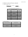
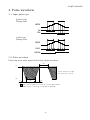
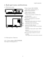
No.QT34-02002A
2 phase stepping motor driver
NanoDrive
SND100 series
【User’s manual】
No.QT34-02002A
Safety precautions
Please read this operation manual thoroughly before starting any operation. This
manual will guide the customers for proper use and avoid any mis-operation. This
manual if properly read, will protect the users as well as other people from possibilities
physical injuries, property damage and other serious accidents.
DANGER
Indicates a possibility of causing serious injury or worst, death
to the user, caused by fire or electric shock if this warning is
ignored. Also indicates that the equipment has the highest degree
of causing damage.
WARNING
This shows the possibility that the user may get serious injury by
fire or electrical shock if this warning is neglected.
This shows the possibility that may cause slight injury or damage
CAUTION to this product or other equipment.
DANGER
l
l
l
l
l
l
l
l
l
l
Do not operate this product if it is damaged or disassembled. Otherwise, it may
cause fire or electrical shock.
In any case, do not attempt to repair or modify this product as it may cause fire,
electrical shock or serious injuries.
Do not use this product, in a place where the air includes a corrosive gas,
inflammable gas, or any type of explosive gas, or the water or oil splashes, or it is
near a flammable material. Otherwise, it may cause fire or electrical shock.
Leave works such as installation, wiring, operation, checking and maintenance to
experts who have enough knowledge on this product. Operation without knowledge
may cause electrical shock and other serious physical or property damages.
Keep the power supply within the rated voltage range. Otherwise, it may cause fire
or other damages.
Make sure all the connections correctly done referring to the wiring diagram shown
in this user’s manual. Otherwise, it may cause fire or other damages.
Do not, in any circumstances, touch the terminal block while the power is on as
there are some terminals which high voltage appeared. Otherwise, it may cause
electrical shock.
Do not touch or place objects such as metals or foreign substance on the board.
Otherwise, it may cause fire or electrical shock.
Do not bend, pull or place the power or motor cables by the extreme force.
Otherwise, it may cause fire or electrical shock.
Do not make a mistake connecting the motor output terminals to protective earth
or power supply. Otherwise, it may cause fire.
No.QT34-02002A
l
l
Do not do the driver’s installation preventing ventilation. Otherwise, it may cause
fire.
When the “HEAT” is activate, stop the pulse signal. Otherwise, it may cause fire.
(Only the product have a Overheat function.)
WARNING
l
l
l
l
l
l
l
l
l
Do not attempt any type of works such as moving the machine, wiring,
maintenance, checking while the power is on. It is recommended that such works
should be done only when more than ten seconds have elapsed after the power is
off. Otherwise, it may cause electrical shock.
Do not touch this product with wet hands while the power is on. Otherwise, it may
cause electrical shock.
Connect the protective earth terminal (PE) properly to it on your equipment, as
illustrated in this user’s manual. Otherwise, it may cause electrical shock.
Use this product which installed properly in the enclosure. Otherwise, it may cause
electrical shock or injury.
Do not leave the cover off from the terminal block while the power is on. Otherwise,
it may cause electrical shock or injury.
Fix this product securely onto your equipment. Otherwise, it may cause injury.
Do not touch this product while it is running or right after it is stopped. Otherwise,
it may cause injury, as its surface remains hot.
Depending on the setting of this product, it may show an unexpected operation
when recovering from overheating. Please read this user’s manual carefully and
pay a special attention.
Use a DC power supply with reinforced insulation for dangerous voltage.
Otherwise, it may cause electrical shock.(Only DC input type)
CAUTION
l
l
l
l
l
l
l
Do not use or store this product under a dusty environment. Otherwise, it may
cause malfunction.
Do not give a big shock to this product. Otherwise, it may cause malfunction.
Do not use or store this product in a place of high or low temperature, or under an
environment of extremely high or low humidity. Otherwise, it may cause short
circuit to your device or further damage.
Do not install this product in a place where a dew is generated. Otherwise, it may
cause short circuit to your device or further damage.
MYCOM is, in no way, responsible for any damages or malfunctions that are
caused by user’s repair or modifications on this driver. If the user performed these
initiations and the driver does not work satisfactorily, a warranty will not be
provided.
When giving up the use of the driver, dispose it according to an appropriate
regulation on the industrial waste.
Please do not remove the name plate.
No.QT34-02002A
INDEX
1. Specification of driver....................................................................................................................1
SND100-220L ..................................................................................................................................1
2. Model number & Factory default................................................................................................2
2-1. Model number of set...............................................................................................................2
2-2. Factory default ........................................................................................................................2
3. Pulse waveform...............................................................................................................................3
3-1. Input pulse type ......................................................................................................................3
3-2. Pulse waveform .......................................................................................................................3
4. Each part name and functions....................................................................................................4
4-1. Each part name .......................................................................................................................4
4-2. Description of function...........................................................................................................4
4-2-1. Power display LED (POWER)......................................................................................4
4-2-2. Resolution select switch (SW 1st - 4th pole) .............................................................5
4-2-3. Auto current down function (A.CD, SW 5th pole)....................................................6
4-2-4. Pulse input type select switch(1P/2P, SW 6th pole )...............................................6
4-2-5. Driving current adjusting volume (C.ADJ)...............................................................6
4-2-6. Power supply connector (CN-1)....................................................................................7
4-2-7. Motor connector (CN-2)..................................................................................................7
4-2-8. Signal input connector (CN-3)......................................................................................7
5. Example Of connection..................................................................................................................7
6. Wiring and Install condition........................................................................................................8
6-1. Wiring for power lines............................................................................................................8
6-2. Wiring for motor lines............................................................................................................8
6-3. Wiring of signal line ...............................................................................................................8
6-4. Install condition ......................................................................................................................8
7. How to Current Adjustment ........................................................................................................9
7-1. Connection and adjustment procedure ..............................................................................9
8.Dimension....................................................................................................................................... 10
8-1. Dimension of SND100-220L.............................................................................................. 10
9. Option............................................................................................................................................. 11
No.QT34-02002A
1. Specification of driver
SND100-220L
Driver model name
Power source
Power consumption
Driving type
Output current
SND100-220L
DC24V±10%
DC24-48V
85W
or less 10
Uni-polar constant current type
2.0A/phase MAX
Resolution
Basic step :
1, 2, 2. 5, 5, 8, 10, 20, 25, 40, 50, 100, 125, 200, 250, 500, 1000
Function
Auto-current down
Signal input
Photo coupler input; Input resistance 220Ω
Input signal voltage: L:0 - 0.5V, H:4 - 5V
1 pulse(PLUSE, CW/CCW), 2 pulses(CW, CCW)
Insulation
resistance
100MΩ or more applied DC 500V megger in normal temperature
and humidity.
・Power input : Motor leads collection terminal - chassis
・Power input : Motor leads collection terminal - signal I/O
Operating environmental
temperature
0 to +40℃ No freezing
Operating environmental
humidity
Less than 80%, No condensation
Storing
environmental
temperature
-10℃ to +60℃ No freezing
Storing humidity
Operating height
Less than 80%, No condensation
Less than 1,000m from sea level
Atmosphere
In the room without corrosive gas, inflammable gas and dust.
Without splashing water and oil
Weight
120g
Accessories
User’s manual(This book)
-1-
No.QT34-02002A
2. Model number & Factory default
2-1. Model number of set
SND100 −220L− 268A
Series name Extension of set
List of motor and driver combination
Series name, SND100
Extension of
set
Motor model
243A(B)
244A(B)
245A(B)
264A(B)
265A(B)
268A(B)
444A(B)
443A(B)
445A(B)
464A(B)
466A(B)
468A(B)
PF243-A(B)
PF244-A(B)
PF245-A(B)
PF264-A(B)
PF265-A(B)
PF268-A(B)
PS444-02A(B)
PS443-01A(B)
PS445-01A(B)
PF464-02A(B)
PF466-02A(B)
PF468-02A(B)
Current
A/phase
0.9
1.2
1.2
2.0
2.0
2.0
0.8
0.95
1.2
2.0
2.0
2.0
2-2. Factory default
Driver model number
SND100-220L
Phase current
Current down value
Auto current down function
Input type
Resolution
2.0 A/phase Max
1.0 A/phase
Auto current down function, valid
2 pulse type
1/1(FULL)
-2-
No.QT34-02002A
3. Pulse waveform
3-1. Input pulse type
2 pulses type
Timing chart
CW
CCW
CW
CCW
MOTOR
MOTOR
CW
CW
CCW
CCW
1 pulse type
Timing chart
MOTOR
MOTOR
PULSE
Pulse
CW/CCW
CW/CCW
3-2. Pulse waveform
Please input the pulse signal of the below shown waveform.
T2
5V
T1,T2:0.2 μsec or longer
T3:0.2 μsec or shorter
0V
T3
T1
T3
←This section shows "ON"status of internal photo coupler.
Motor starts to rotate by rising edge of waveform.
-3-
No.QT34-02002A
4. Each part name and functions
4-1. Each part name
⑥
1
1 1
②
③
④
①Power display LED (POWER)
This rights on during power on.
②Power connector(CN-1)
This connects to power
③Motor connector (CN-2)
Connect in accordance with the color
of motor leads.
④Signal I/O connector(CN-3)
Various I/O signals are connected.
⑤Switching
・Resolution select switch: 1st-4th pole
This selects the resolution.
⑤
・Switching of Auto current down
function (A.CD) : 5th pole
①
This turns on/off the auto current down
function.
・Switching of input pulse input (1P/2P) :
6th pole
This switches the input pulse type.
⑥Current adjust volume for current
(C.ADJ)
This adjusts the current when currennt.
4-2. Description of function
4-2-1. Power display LED (POWER)
This rights on during power on.
-4-
No.QT34-02002A
4-2-2. Resolution select switch (SW 1st - 4th pole)
Resolution select switch(4-1.Each Part name⑤, SW 1st-4th pole) can set 16 various
resolutions individually.
No. 1
No. 2
No. 3
No. 4
No. 5
No. 6
No. 7
No. 8
No. 9
No. 10
No. 11
No. 12
No. 13
No. 14
No. 15
No. 16
Resolution
1/1
1/2
1/2.5
1/5
1/8
1/10
1/20
1/25
1/40
1/50
1/100
1/125
1/200
1/250
1/500
1/1000
No.1 1/1
No.2 1/2
1
1
1
1
2
2
2
2
3
3
3
3
4
4
4
4
5
5
5
5
6
ON
6
ON
6
ON
6
ON
No.5 1/8
No.6 1/10
No.3 1/2.5
No.7 1/20
No.4 1/5
No.8 1/25
1
1
1
1
2
2
2
2
3
3
3
3
4
4
4
4
5
6
5
6
5
6
5
6
ON
ON
ON
ON
No.9 1/40
No.10 1/50
No.11 1/100 No.12 1/125
1
1
1
1
2
2
2
2
3
3
3
3
4
5
4
5
4
5
4
5
6
6
6
6
ON
ON
ON
ON
No.13 1/200 No.14 1/250 No.15 1/500 No.16 1/1000
1
1
1
1
2
2
2
2
3
4
3
4
3
4
3
4
5
5
5
5
6
6
6
6
ON
ON
ON
ON
-5-
No.QT34-02002A
4-2-3. Auto current down function (A.CD, SW 5th pole)
This automatically reduces the motor driving
current to 50%(default) of normal current to
reduce temperature rising of motor after the
motor stops and 200ms. later.
OFF/A.CD switch (4-1. Each part name⑤, SW
5th pole) can release the function.
Auto current down valid Auto current down invalid
1
1
2
2
3
3
4
4
5
5
6
6
ON
ON
4-2-4. Pulse input type select switch(1P/2P, SW 6th pole )
1P/2P switch sets the driving pulse to 1 pulse
type or 2 pulses type.
(4-1. Each part name⑤, SW 6th pole) Please
refer “3. Pulse wave ” about input type.
CAUTION
1 pulse type 2 pulse type
1
1
2
2
3
3
4
4
5
5
6
ON
6
ON
・ When automatic current down release is carried out, compulsive air
cooling is required for the driver.
・ When automatic current down release is carried out, be careful of heat
generation of a motor and a driver.
4-2-5. Driving current adjusting volume (C.ADJ)
C.ADJ volume (4-1. Part name⑥) adjusts the value of motor driving current.
About 0.8A
About 0.5A
About 1A
About 1.3A
About 1.5A
About 0.3A
About 1.8A
About 0A
About 2A
About 0A
(MIN)
Attention
Left figure shows the position of volume
adjusted about 2A.
About 2.1A
(MAX)
・ The above figure of volume is approximate value.
・ There is a possibility to flow over current if volume is turned into
the end position(MAX) of clockwise direction. Pay attention for the
heating of a motor and a driver.
-6-
No.QT34-02002A
4-2-6. Power supply connector (CN-1)
Connector pin assignment
DC24V and 0V are connected.
4-2-7. Motor connector (CN-2)
This is connected according to the motor lead color.
1
DC24V
2
0V
Connector pin assignment
1 ACOM
4 /A phase
2 BCOM
5 B phase
3 A phase
6 /B phase
4-2-8. Signal input connector (CN-3)
This is to be connected with driving pulse signal.
1 pulse mode
1 PULSE+
2 PULSE−
3 CW/CCW+
4 CW/CCW−
2
1
2
3
4
pulses mode
CW+
CW−
CCW+
CCW−
5. Example Of connection
SND100 series
Controller
Twisted pair wire
(NMM-101 series )
PF series motor
Photo coupler
CW +
D r i v e r s e n s o r in p u t
CW −
2 20Ω
CCW +
CCW −
2 20Ω
ACOM
BCOM
A
/A
B
RED
BLU
BLK
BRN
YEL
ORE
/B
DC24V
+
0V
−
DC Power supply
-7-
No.QT34-02002A
6. Wiring and Install condition
6-1. Wiring for power lines
・Install noise filter at power input where noise sources exist near the driver or there
are effects of power noise.
6-2. Wiring for motor lines
・The radiant noise may be avoided by sealed line if unnecessary radiation causes
troubles.
6-3. Wiring of signal line
If the following procedure is not made, there may be a cause of incorrect operation.
・Use bigger cable than AWG28 which suits with the connector.
・Use twisted pair line or shield line.
6-4. Install condition
・Use in control box.
・Fix the driver on heat conductive earthed metal plate tightly.
・Put 3cm or more space between each driver and fix the drivers when multiple drivers
are arranged.
・Because this unit uses high speed photo coupler for the part of input pulse, use the
shield line for signal cable. Also do not connect the signal line which is not used. It
becomes the cause of incorrect operation.
・Use M3 screws of length of “thickness of installing place plus 3mm”.
Attention
There is a possibility that driver heat sink temperature exceeds 60 centimeter degree
depending on loading or environmental condition.
-8-
No.QT34-02002A
7. How to Current Adjustment
7-1. Connection and adjustment procedure
・As shown in the figure below, connect ACOM and BCOM of driver with “+” of
ammeters. Connect ACOM and BCOM of motor with “−“ of ammeters.
・Power driver on after turning C.ADJ volume until MIN position, which is end of
clockwise direction, and setting resolution 1/1.
・Turn auto-current down OFF (invalid)
・Adjust driving current by C.ADJ volume.
Adjust the current to double value of motor rated current.
As shown in the connection figure below, in case that the rated current of motor is
2A, twice of rated current are required to adjust the current for two phase by one
ammeter.
Ex. In case that the rated current of motor is 2A,
2A x 2 = 4A
Ex. In case that the rated current of motor is 1.2A,
1.2A x 2 =2.4A
・Turn auto-current down ON (valid)
Attention
・Make sure the rating of ammeters and connect to motor and driver.
・Connect two “COM” with ammeters without fail.
・ There is a possibility to flow over current if volume is turned into the end
position(MAX) of clockwise direction.)
SN D 1 0 0
+
ACOM
BCOM
A
/A
B
/B
−
Ammeter
Motor
-9-
No.QT34-02002A
8.Dimension
5mm or more
8-1. Dimension of SND100-220L
106
61
67
3mm or less
3.5
2-φ3.5
1
6
6
1 1
6
6
90
Unit: mm. (The screw head is not included.)
-10-
29
26.6
11
96
No.QT34-02002A
9. Option
It is available to supply the following optional cables which have covering connector at
the one side.
・CN1 : Power cable
Model number : OPC-IL2P3
Connector : IL-G-2S-S3C2-SA *1
Cable : AWG22 lose line 3m
Loose cable AWG22 3m
・CN2 : Motor cable
Model number : OMC-IL6P3
Connector : IL-G-6S-S3C2-SA *1
Cable : AWG22 lose line 3m
Loose cable AWG22 3m
・CN3 : Pulse cable
Model number : OSC-IL4P3
Connector : IL-G-4S-S3C2-SA *1
Cable : AWG24 shield line 3m
Twisted pare cable AWG24 3m
Black
Red
IL-G-2SS3C2-SA
3m
Orange
Yellow
Brown
Brack
Blue
Red
IL-G-6SS3C2-SA
3m
Brown
Red
Orange
Yellow
IL-G-4SS3C2-SA
*1= J.A.E brand housing (Contact, IL-G-C2-SC-10000 is used)
-11-
3m
No.QT34-02002A
・Bracket
Model number; SND100-OPM-01
106
10
98
5
34
96
23
3.5
5
69
55
4-φ3.5
-12-
No.QT34-02002A
Please understand that we may make modifications to our products without notification
in order to improve the capabilities and external appearance of our products.
MYCOM, INC. (Head office)
12, S. Shimobano, Saga hirosawa, Ukyo, Kyoto, Japan 616-8303
TEL: 81-75-882-3601
FAX : 81-75-882-6531
Home Page : http//www.mycom-japan.co.jp/
NYDEN CORP.
2610,North First St. #B San Jose, Ca, 95134, USA
TEL: 1-408-232-7700
Home Page: http//www.nyden.com
MYCOM TECHNOLOGY, INC.
2Fl., No.333, Fuhsing N, Road Taipei, Taiwan, R.O.C.
TEL : 886-2-2719-0525
MYCOM KOREA, INC.
Rm.301, Keum Chang Bldg. #328-1, 6Ka, Dangsan-Dong Yeoung Dungpo-ku Seoul,
Korea
TEL : 82-2-2635-6703
MYCOM THCHNOLOGY (SINGAPORE) PTE. LTD.
No.1, Sims Lane #05-05, One Sims Lane, Singapore 387355
TEL : 65-6743-4476
Home Page : http//www.mycommts.com.sg
Malaysian Contact;
No.1E-12-07, Jalan Batu Uban, Sunny Ville, Penang, Malaysia
TEL : 60-04-656-0328
-13-