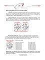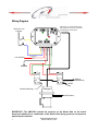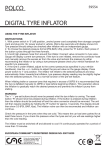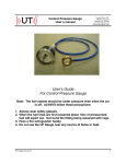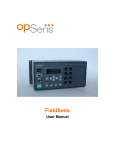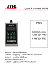
1
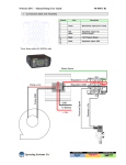
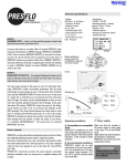
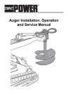
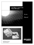
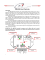
AMS-500 Boost Controller
Overview
The AMS-500 Boost Controller can control 2-Stages and/or levels of boost. The 2Stages are controlled by Input1 and Input2. Both of these inputs can be configured using a DIP
Switch for either Ground or +12 volt activation. Input1 may be configured to function as a
“Launch” stage when used in conjunction with Input2. Input2 offers an adjustable ramp rate as
well as boost level settings.
Each stage has a range of adjustment from 0 to 40psi with 1psi resolution and is controlled to within .1psi to target using advanced control algorithms. If a setting greater than
40psi is configured the AMS-500 will default to the maximum 40psi allowed. A setting of 0psi
will turn either stage off.
An optional Safe Mode is available when using a pressure source other than the manifold pressure. The Safe Mode continually checks for the proper pressure increase and will disable the system and open the decrease solenoid in the event of an error condition. When in
Normal Mode of operation the AMS-500 will keep trying to apply pressure to the waste gate
until its target is reached.
For more information on each individual option see the appropriate section listed in the
Table of Contents on Page 2.
IMPORTANT—The AMS-500 controls the pressure on the Waste Gate so the actual
boost level obtained is a combination of the Waste Gate Spring pressure and pressure
applied by the controller.
Input Polarity Select
DIP Switch
456
O
N
78
23
456
901
23
1’s
78
10’s
1 2
Stage1 Programming
Switches
MAP Sensor Port
1/8 NPT
901
Stage1 LED
Power
23
901
23
23
1’s
DEC SOL
INC SOL
GROUND
SOL+
F0 1
+12 VOLT
INPUT2
1
INPUT1
Stage2 Ramp Rate
Select Switch
901
10’s
456
78
78
456
789
CD
AB E
4 56
Stage2 LED
Stage2 Programming
Switches
Table of Contents
Configure AMS-500 Operating Mode
Page 3
Configure Stage1 / Input1 Operating Mode
Page 4
Setting Input1 and Input2 Activation Polarity
Page 5
Setting Stage1 Boost Level
Page 5
Setting Stage2 Boost Level and Ramp Rate
Page 6
Wiring Diagram
Page 7
Warranty Information
Page 8
Notice—It is the responsibility of the purchaser to follow all guidelines and safety procedures
supplied with this product and any other manufactures product used with the AMS-500. It is
also the responsibility of the purchaser to determine compatibility of the AMS-500 with the
vehicle and other components.
NLR, LLC assumes no responsibility for damages resulting from accident, improper
installation, misuse, abuse, improper operation, lack of reasonable care, or all previously
stated reasons due to incompatibility with other manufacturer’s products.
NLR, LLC assumes no responsibility or liability for damages incurred from the use of
products manufactured or sold by NLR, LLC on vehicles used for competition racing.
NLR, LLC neither recommends nor approves the use of products manufactured or sold
by NLR, LLC on vehicles which may be driven on public highways or roads, and assumes no
responsibility for damages incurred from such use.
NLR, LLC does not recommend nor condone the use of its products for illegal street
racing.
Installation of NLR, LLC products signifies that you have read this document and
agree to the terms stated within.
Important Information:
Follow all recommended safety guidelines from this and other manufactures installation
guides. Static suppression ignition wires must be used with this unit! Mount the unit as far
away from secondary ignition components (coil, ignition wires, etc.) as physically possible.
IMPORTANT—The AMS-500 controls the pressure on the Waste Gate so the actual
boost level obtained is a combination of the Waste Gate Spring pressure and pressure
applied by the controller
2
www.nlrsystems.com or
Phone 334-741-7100
Configure AMS-500 Operating Mode
Normal Mode—When the AMS-500 is configured for Normal Mode of operation it will
always attempt to reach the target pressure setting by operating the increase solenoid. If there
is not enough pressure in the system to achieve the target level the AMS-500 will keep trying
to apply pressure to the waste gate until its target is reached. When in Normal Mode the Red
LED will be on steady at power to indicate this mode is active.
Safe Mode—When the AMS-500 is configured for Safe Mode of operation it will attempt to reach the target pressure level, if no increase in pressure is detected the system will
turn off the increase solenoid and open the decease solenoid. After one second another attempt will be made to reach the desired target pressure. After three failed attempts the AMS500 will flash the Red and Green LED’s to indicate a pressure increase error and open the decrease solenoid. It will remain this way until power is turned off and back on to reset the system. When in Safe Mode the Red LED will flash 4 times at power up to indicate this mode is
active.
Switching between modes of operation
1—Set all Stage1 and Stage2 switches to 0 including the Ramp Rate switch.
2—Turn AMS-500 on, the Red LED will blink once per second for 60 seconds. To
change operating mode you must wait 60 seconds with the Red LED blinking.
3—After 60 seconds the AMS-500 will automatically switch operating modes. The new
operating mode selected will be indicated by flashing the Red / Green LED’s in the patterns
listed below. Use the LED flash pattern to determine the current mode of operation.
Safe Mode—Red and Green LED’s will blink in a circular pattern.
Normal Mode—Red and Green LED’s will blink in an alternating pattern.
4—Turn power off, set switches for desired target psi and ramp rate for Stage2.
5—Turn power back on and AMS-500 is ready to operate in selected mode.
IMPORTANT—At least one Stage Programming switch must be non-zero for operation.
IMPORTANT—The AMS-500 controls the pressure on the Waste Gate so the actual
boost level obtained is a combination of the Waste Gate Spring pressure and pressure
applied by the controller
3
www.nlrsystems.com or
Phone 334-741-7100
Configure Stage1 / Input1 Operating Mode
Normal Mode—When Stage1 and/or Input1 is configured for Normal operation the AMS-500
will immediately apply the pressure selected with the Stage1 Programming switches when Input1 becomes active. If Stage2 / Input2 is active the Stage1 setting will override the Stage2 setting.
Example—Stage1 set at 12psi, Stage2 psi set at 8psi. When Stage1 is activated the AMS-500 would apply 12psi to the system whether Stage2 is active or not. The Stage2 Green LED will blink four times at
power up to indicate this mode is active.
Launch Mode—When Stage1 / Input1 is configured for Launch Mode operation the AMS-500
will ignore the Stage2 / Input2 activation until Input1 is released. This allows a Launch psi to be set for
Stage1 and then Stage2 can be used to Ramp the target pressure up / down after the launch. Typical operation would be to connect Input1 to a clutch and/or trans brake switch and Input2 to a wide open throttle switch. The Stage1 Green LED will blink four times at power up to indicate this mode is active.
Switching between modes of operation
1—Set Stage1 and Stage2 programming switches to 0. Set Stage2 Ramp Rate select
switch to 1.
2—Turn AMS-500 on, the Red LED will blink once per second for 60 seconds. To
change Stage1 operating mode you must wait 60 seconds with the Red LED blinking.
3—After 60 seconds the AMS-500 will automatically switch Stage1 operating modes.
The new operating mode selected will be indicated by flashing the either the Stage or Stage2
Green LED. Use the guide below to determine the current Stage1 Mode selected.
Normal Mode—Stage2 Green LED will blink 5 times per second.
Launch Mode—Stage1 Green LED will blink 5 times per second.
4—Turn power off, set switches for desired target psi and ramp rate for Stage2.
5—Turn power back on and AMS-500 is ready to operate in selected mode.
IMPORTANT—At least one Stage Programming switch must be non-zero for operation.
IMPORTANT—The AMS-500 controls the pressure on the Waste Gate so the actual
boost level obtained is a combination of the Waste Gate Spring pressure and pressure
applied by the controller
4
www.nlrsystems.com or
Phone 334-741-7100
Setting Input1 and Input2 Activation Polarity
Overview—Input1 and Input2 can be configured for either Ground activation or +12
volt activation. This allow the AMS-500 to be used with existing wiring configurations already
installed.
The Inputs are configured using the 2-position Input Polarity Select DIP switch.
1 2
O
N
Setting Input1 Polarity—DIP Switch #1 OFF for Ground Activation and Switch #1 ON
for +12 volt activation.
Setting Input2 Polarity—DIP Switch #2 OFF for Ground Activation and Switch #2 ON
for +12 volt activation.
Setting Stage1 Boost Level
Overview—The Stage1 Programming switches are used to set the target psi when Input1 is active. This setting will either determine Stage1 target psi or Stage1 Launch psi, see
“Configure Stage1 / Input1 Operating Mode” for more information.
Setting Target Psi—There are two Stage1 target psi programming switches. These
are used together to represent the target psi desired. Example—24psi setting, set Stage1, 10’s
switch to 2 and then 1’s switch to 4. If a setting greater than 40psi is used the AMS-500 will
default to a 40psi setting for this stage. Please see diagram below.
23
456
901
23
456
78
1’s Switch
78
10’s Switch
901
Stage1 Programming Switches.
IMPORTANT—The AMS-500 controls the pressure on the Waste Gate so the actual
boost level obtained is a combination of the Waste Gate Spring pressure and pressure
applied by the controller
5
www.nlrsystems.com or
Phone 334-741-7100
Setting Stage2 Boost Level and Ramp Rate
Overview—The Stage2 Programming switches are used to set the target psi when Input2 is active. To determine the Ramp Rate of Stage2 see instructions below. When Stage1 is
configured for Launch Mode Input2 activation will be ignored until Input1 is released. See
“Configure Stage1 / Input1 Operating Mode” for more information.
Setting Target Psi—There are two Stage2 target psi programming switches. These
are used together to represent the target psi desired. Example—15psi setting, set Stage2, 10’s
switch to 1 and then 1’s switch to 5. If a setting greater than 40psi is used the AMS-500 will
default to a 40psi setting for this stage. Please see diagram below.
23
456
901
23
456
78
1’s Switch
78
10’s Switch
901
Stage2 Programming Switches.
Setting Stage2 Ramp Rate—There are 16 Ramp Rates available for Stage2 boost
control. These are selected using the Stage2 Ramp Rate Select Switch. A setting of 0 will result in the target pressure being applied immediately when Stage2 is active. See chart below
for other Ramp Rates. The Ramp Rates are defined as psi per second.
23
789
CD
AB E
4 56
Stage2 Ramp Rate
Select Switch
Psi per second settings.
0 = Maximum ramp rate.
1 = 1psi per second.
2 = 2psi per second.
3 = 3psi per second.
4 = 4psi per second.
5 = 5psi per second.
6 = 6psi per second.
7 = 7psi per second.
8 = 8psi per second.
9 = 9psi per second.
A = 15psi per second.
B = 20psi per second.
C = 30psi per second.
D = 40psi per second.
E = 50psi per second.
F = 60psi per second.
F0 1
IMPORTANT—The AMS-500 controls the pressure on the Waste Gate so the actual
boost level obtained is a combination of the Waste Gate Spring pressure and pressure
applied by the controller
6
www.nlrsystems.com or
Phone 334-741-7100
Wiring Diagram
1 2
O
N
23
Increase Solenoid
Ground
Solenoid +12 Volt
Decrease Solenoid
23
23
Input2
F0 1
Input1
+12 Volt
23
23
901
4 56
901
10 Amp Fuse
456
78
CD
AB E
+12V Switched
78
456
789
MAP Sensor port, 1/8 NPT threads. Install
desired fiting here and connect to Solenoids
and Wastegate as outlined below.
901
78
456
901
456
78
Connect to +12V
or Ground.
GROUND
Decrease
Solenoid
OUT
Increase
Solenoid
IN
OUT
EXH
Do NOT Install Plug
IN
EXH
Air Supply or
Manifold Pressure
1/8 NPT
Plug
Wastegate
Manifold Pressure
IMPORTANT—The AMS-500 controls the pressure on the Waste Gate so the actual
boost level obtained is a combination of the Waste Gate Spring pressure and pressure
applied by the controller
7
www.nlrsystems.com or
Phone 334-741-7100
Warranty Information
NLR warrants to the original purchaser that the AMS-500 Controller Shall be free from defects
in parts and workmanship under normal use for 6 months from the date of purchase.
NLR obligation under this warranty is limited to the repair or replacement of any component
found to be defective when returned postpaid to NLR.
The Controller must be returned with evidence of place and date of purchase or warranty will be
void. The warranty will not apply if the AMS-500 Controller has been installed incorrectly, repaired,
damaged, or tampered with by misuse, negligence or accident.
IMPORTANT—The AMS-500 controls the pressure on the Waste Gate so the actual
boost level obtained is a combination of the Waste Gate Spring pressure and pressure
applied by the controller
8
www.nlrsystems.com or
Phone 334-741-7100