1
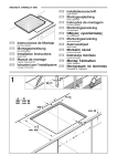
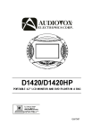
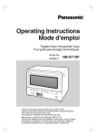
Quick Start Guide
7500 Series Modular
Data Center Switches
DCS-7508 / 7508E
DCS-7504 / 7504E
Arista Networks
www.arista.com
PDOC-00015-07
Headquarters
Support
Sales
408 547-5500
408 547-5502
866 476-0000
408 547-5501
866 497-0000
www.arista.com
[email protected]
[email protected]
5453 Great America Parkway
Santa Clara, CA 95054
USA
© Copyright 2015 Arista Networks, Inc. The information contained herein is subject to change without notice. Arista Networks
and the Arista logo are trademarks of Arista Networks, Inc in the United States and other countries. Other product or service names
may be trademarks or service marks of others.
Chapter 1: Overview
Chapter 1 Overview
1.1
Scope
This guide is intended for properly trained service personnel and technicians who need to install the
following Arista Networks Data Center Switches:
•
•
DCS-7504 / 7504E
DCS-7508 / 7508E
Important! Only qualified personnel should install, service, or replace this equipment.
1.2
Receiving and Inspecting the Equipment
Upon receiving the switch, inspect the shipping boxes and record any external damage. Retain packing
materials if you suspect that part of the shipment is damaged; the carrier may need to inspect them.
If the boxes were not damaged in transit, unpack them carefully. Ensure that you do not discard any
accessories that may be packaged in the same box as the main unit.
Inspect the packing list and confirm that you received all listed items. Compare the packing list with
your purchase order. Appendix B provides a list of components included with the switch.
1.3
Installation Process
The following tasks are required to install and use the switch:
Step 1
Step 2
Step 3
Step 4
Step 5
Select and prepare the installation site (Section 2.1).
Assemble the installation tools listed in Section 2.2.
Attach the mounting brackets and install the switch in an equipment rack (Chapter 3).
Connect the switch to the power source and network devices (Chapter 4).
Configure the switch (Chapter 5).
Important! Class 1 Laser Product: This product has provisions to install Class 1 laser transceivers that provides
optical coupling to the communication network. Once a Class 1 laser product is installed, the
equipment is a Class 1 Laser Product (Appareil à Laser de Classe 1). The customer is responsible for
selecting and installing the Class 1 laser transceiver and for insuring that the Class 1 AEL (Allowable
Emission Limit) per EN/IEC 6-825, CSA E60825-1, and Code of Federal Regulations 21 CFR 1040 is not
exceeded after the laser transceiver have been installed. Do not install laser products whose class rating
is greater than 1. Refer to all safety instructions that accompanied the transceiver prior to installation.
Only Class 1 laser devices certified for use in the country of installation by the cognizant agency are to
be utilized in this product.
Important! Ultimate disposal of this product should be handled in accordance with all national laws and
regulations.
1.4
Safety Information
Refer to the Arista Networks document Safety Information and Translated Safety Warnings available at:
http://www.arista.com/support/docs/eos
7500 Series Modular Switch Quick Start Guide
PDOC-00015-07
3
Chapter 1: Overview
1.5
Obtaining Technical Assistance
Any customer, partner, reseller or distributor holding a valid Arista Service Contract can obtain technical
support in any of the following ways:
•
Email: [email protected]. This is the easiest way to create a new service request.
Include a detailed description of the problem and the output of “show tech-support”.
•
Web: www.arista.com/support.
A support case may be created through the support portal on our website. You may also download
the most current software and documentation, as well as view FAQs, Knowledge Base articles,
Security Advisories, and Field Notices.
•
Phone: 866-476-0000 or 408-547-5502.
Important! No user serviceable parts inside. Refer all servicing to qualified service personnel.
1.6
Specifications
Table 1 lists the specifications of Arista Data Center modular switches covered by this guide.
Table 1: Modular Switch Specifications
DCS-7508 / DCS-7508E
DCS-7504 / DCS-7504E
Height
11U: 485 mm (19.1inches)
7 U: 312 mm (12.25 inches)
Width
483 mm (19 inches)
483 mm (19 inches)
Depth
762 mm (30 inches)
762 mm (30 inches)
Weight
136 kg (300 pounds)
95 kg (210 pounds)
Input Power (per circuit)
200/240 VAC, 50 or 60 hz, 20 A
200/240 VAC, 50 or 60 hz, 20 A
Input Power Circuits
2 to 4 circuits
1 to 4 circuits
Ambient Temperature
Storage Temperature
Relative Humidity
Altitude
0° to 40° C (32° to 104° F)
-40° to 70° C (-40° to 158° F)
5 to 90%
0 to 3,000 meters (0 to 10,000 feet)
0° to 40° C (32°to 104° F)
-40° to 70° C (-40° to 158° F)
5 to 90%
0 to 3,000 meters (0 to 10,000 feet)
Cooling
6600 W maximum
3300 W maximum
Table 2 lists power specifications of modular switch components.
Table 2: 7500 Series Power Specifications
Module Type
Supervisor Modules
Power Draw (Typical / Maximum)
DCS-7500E-SUP
180 W / 105 W
DCS-7500E-36Q-LC
DCS-7500E-72S-LC
DCS-7500E-48S-LC
DCS-7500E-12CM-LC
DCS-7500E-6C2-LC
DCS-7500E-12CQ-LC
DCS-7500E-48T-LC
450 W / 556 W
212 W / 305 W
197 W / 285 W
408 W / 495 W
300 W / 320 W
414 W / 486 W
318 W / 332 W
Fabric Modules
DCS-7504E-FM
DCS-7508E-FM
80 W / 105 W
155 W / 195 W
7500 Series System
DCS-7504 with DCS-7548S-LC
DCS-7508 with DCS-7548S-LC
2124 W / 2778 W
3806 W / 4520 W
Linecard Modules
4
Part Number
Arista Networks
Copyright 2015
Chapter 2: Preparation
Chapter 2 Preparation
2.1
Site Selection
The following criteria should be considered when selecting a site to install the switch:
•
Floor Space: Install the switch in an area that provides adequate clearance for removing front and
rear components. Figure 1 displays switch clearance requirements.
Figure 1: Switch Component Removal Footprint
•
Temperature and Ventilation: For proper ventilation, install the switch where there is ample airflow
to the front and back of the switch. The temperature should not go below 0° or exceed 40° C.
Important! To prevent the switch from overheating, do not operate it in an area where the ambient temperature
exceeds 40°C (104°F).
•
Airflow Orientation: The fans direct air from the front panel to the rear panel. Orient the front
panel toward the cool aisle.
•
Rack Space: Install the switch in a 19" rack or cabinet. The switch height is 11 RU (7508 / 7508E) or
7 RU (7504 / 7504E). The accessory kit provides mounting brackets for two-post and four-post racks.
When mounting the switch in a partially filled rack, load the rack from bottom to top, with the
heaviest equipment at the bottom. Load the switch at the bottom if it is the only item in the rack.
•
Power Requirements: The 7508 / 7508E switch requires two 200-240 VAC, 50 or 60 Hz, 20 A circuits.
The 7504 / 7504E switches require one 200-240 VAC, 50 or 60 Hz, 20 A circuit.
Four circuits provide redundancy protection. The switch uses power cables that comply with
IEC-320 and have a C19 plug. The accessory kit provides four IEC-320 C19 to C20 power cables, each
two meters long.
Important! All power input plug-socket combinations must be accessible at all times; they provide the primary
method of disconnecting power from the system.
•
Other Requirements: Select a site where liquids or objects cannot fall onto the equipment and
foreign objects are not drawn into the ventilation holes. Verify these guidelines are met:
— Clearance areas to the front and rear panels allow for unrestricted cabling.
— All front and rear panel indicators can be easily read.
— AC power cords can reach from the AC power outlet to the connectors on the front panel.
Important! Disconnecting power to all input sockets is required to completely power off the unit.
7500 Series Modular Switch Quick Start Guide
PDOC-00015-07
5
Chapter 2: Preparation
2.2
Tools Required for Installation
The following tools are required to install a modular switch:
•
•
•
•
Mechanical device capable of lifting chassis being installed (Table 1).
Adjustable wrench (provided)
Phillips #2 screwdriver
Phillips #3 screwdriver
Two-post rack mounts:
•
•
Eight equipment rack screws (all two-post rack mounts).
Eight equipment rack nuts (two-post rack mount with unthreaded rack post holes).
Four-port rack mounts:
•
Eight equipment rack screws (four-post rack mount with threaded rack post holes).
Accessory kit provides rack screws for four-post rack mount with unthreaded rack post holes.
The accessory kit includes screws that fit many common equipment racks.
2.3
Electrostatic Discharge (ESD) Precautions
Observe these guidelines to avoid ESD damage when installing or servicing the switch.
•
•
•
•
•
•
•
6
Assemble or disassemble equipment only in a static-free work area.
Use a conductive work surfaces (such as an antistatic mat) to dissipate static charge.
Wear an ESD wrist strap to dissipate static charge accumulation.
Minimize handling of assemblies and components.
Keep replacement parts in their original static-free packaging.
Remove all plastic, foam, vinyl, paper, and other static-generating materials from the work area.
Use tools that do not create ESD.
Arista Networks
Copyright 2015
Chapter 3: Rack Mounting the Switch
Chapter 3 Rack Mounting the Switch
The accessory kit provides components for installing the switch in two-post and four-post racks.
•
•
Section 3.1 provides instructions for mounting the switch in a two-post rack.
Section 3.2 provides instructions for mounting the switch in a four-post rack.
The rack mounting procedure is identical for all modular switches. Illustrations in this chapter depict
the mounting of an unpopulated DCS-7508 chassis.
After completing the instructions for your rack type, proceed to Chapter 4.
3.1
Two-Post Rack Mount
To mount the switch to a two-post rack, assemble mounting brackets to the middle of the chassis, then
attach the brackets to the rack. The switch does not support a front or rear mount into a two-post rack.
The accessory kit includes the following two-post mounting parts:
•
•
2 center-mount brackets
20 M4x8 panhead Phillips screws
Figure 23 displays the two-post mounting parts.
3.1.1
Attaching Mounting Brackets to the Chassis
Step 1 Orient the switch chassis and the two center-mount brackets (Figure 2).
Position the flanges that attach to the rack posts toward the rear of the chassis.
Step 2 Attach both center-mount brackets to the chassis.
Each bracket requires ten M4x8 panhead Phillips screws.
Figure 2: Attaching the Center-mount Brackets
7500 Series Modular Switch Quick Start Guide
PDOC-00015-07
7
Chapter 3: Rack Mounting the Switch
3.1.2
Inserting the Switch into the Rack
Step 1 Move the chassis to the rack using a mechanical lift (Figure 3).
If modules are inserted in the chassis, use the lift carefully to avoid damaging any components.
Step 2 Lift the chassis into the rack. Position the flanges against the rack posts (Figure 3).
Figure 3: Lifting the Switch Chassis into the Two Post Rack
Step 3 Select mounting screws that fit your equipment rack.
A minimum of four screws is required on each side of the chassis. The accessory kit provides
screws that fit many common equipment racks. When installing the switch into a rack with
unthreaded post holes, nuts are also required to secure the switch to the rack posts.
Step 4 Attach the bracket flanges to the rack posts (Figure 4). Space the screws evenly along the flange.
Figure 4: Attaching Flanges to the Rack Post
After completing the two-post installation, proceed to Chapter 4.
3.2
Four-Post Rack Mount
The switch is mounted onto a four-post rack by assembling a shelf into the rack, then placing the switch
on the shelf.
8
Arista Networks
Copyright 2015
Chapter 3: Rack Mounting the Switch
The accessory kit provides the following four-post mounting parts:
•
•
•
•
•
2 front brackets
4 shelf supports
2 back brackets (not needed for racks with threaded holes)
left shelf
right shelf
Figure 24 displays the four-post mounting parts.
3.2.1
Assembling the Shelf
Step 1 Attach the front bracket and shelf support to the left front rack post, as shown in Figure 5. An
up arrow is printed on the shelf support to indicate its proper orientation.
Unthreaded rack holes: Use the M6 screws and cage nuts supplied in the accessory kit.
Threaded rack holes: Attach the front bracket to the post with screws that can be threaded
through the rack post. Secure the shelf support to the post with nuts that fit the screws threaded
through the post.
Figure 5: Left Front Post Assembly: Four Post Rack Mount
Step 2 Repeat step 1 on the right front rack post, assembling the parts at the same vertical level as those
on the left rack post.
Step 3 Attach the shelf support and back bracket to the left rear post (Figure 6-left). The shelf support
must be assembled at the same vertical level on the front and rear posts (Figure 6-right). An up
arrow is printed on the shelf support to indicate its proper orientation.
Unthreaded rack holes: Attach the parts as displayed in Figure 6-left.
Threaded rack holes: Attach the shelf support to the post with screws that thread into the rack
post. The back bracket is not required on threaded racks.
Step 4 Adjust the left shelf by sliding its components to fit between the front left and front rear rack
posts, as shown in Figure 7.
7500 Series Modular Switch Quick Start Guide
PDOC-00015-07
9
Chapter 3: Rack Mounting the Switch
Figure 6: Left Rear Post Assembly and Shelf Support Orientation: Four Post Rack Mount
Figure 7: Adjusting the Left Shelf
Step 5 Lift the left shelf above the shelf supports installed on the left front and left rear rack posts
(step 1 and step 3). Align the holes (Inset A) and hook (Inset B) with the stubs on the brackets.
Lower the shelf such that the bracket stubs are inserted into the shelf holes and hook.
Press down firmly on the shelf to ensure it is seated securely on the rack posts..
Step 6 Install the right shelf on the right front and right rear rack posts by repeating step 4 and step 5
to obtain the rack configuration shown in Figure 9.
10
Arista Networks
Copyright 2015
Chapter 3: Rack Mounting the Switch
Figure 8: Seating the Left Shelf
Figure 9: Both Switch Shelves Installed
7500 Series Modular Switch Quick Start Guide
PDOC-00015-07
11
Chapter 3: Rack Mounting the Switch
3.2.2
Inserting the Switch into the Rack
Step 1 Move the chassis to the rack using a mechanical lift (Figure 10).
If modules are inserted in the chassis, use the lift carefully to avoid damaging any components.
Figure 10: Lifting the Switch Chassis
Step 2 Lift the chassis into the rack.
Step 3 Secure the chassis by tightening the four thumbscrews on the front flanges into the rack posts
(Figure 11).
Figure 11: Inserting the Switch onto the Rack Shelf
After completing the Four-Post Installation, proceed to Chapter 4.
12
Arista Networks
Copyright 2015
Chapter 4: Cabling the Modular Switch
Chapter 4 Cabling the Modular Switch
4.1
Grounding the Switch
After mounting the switch into the rack, connect the switch to the data center ground. Figure 12
displays the location of the grounding pads located on both sides of the power input sockets.
Figure 12: Grounding Pad and ESD Grounding Port Sockets
After the switch is grounded, ESD wrist straps can be grounded by connecting them to one of the ESD
grounding ports located between the power input sockets, (Figure 12) or the rear panel (Figure 13
depicts the location on the 7504. Receptacles are available in similar locations on other switch models).
Figure 13: ESD Grounding Port – Rear Panel
4.2
Connecting Power Cables
Important! Installation of this equipment must comply with local and national electrical codes. If necessary, consult
with the appropriate regulatory agencies and inspection authorities to ensure compliance.
The switch operates with four power supplies, each of which connects to circuits that provide 200-240
VAC, 50 or 60 Hz, and 20 A.
•
•
DCS-7508 / 7508E requires the connection of at least two power supplies to active circuits.
DCS-7504 / 7504E requires the connection of one power supply to an active live circuit.
Connecting power to all four power supplies protects against up to two failed power supplies and can
provide grid-level redundancy. Energizing any power supply causes all power supply fans to function.
7500 Series Modular Switch Quick Start Guide
PDOC-00015-07
13
Chapter 4: Cabling the Modular Switch
Figure 14 displays the power input sockets. Appendix C displays the front panel location of the sockets.
Figure 14: Power Input Sockets
Important! Read all installation instructions before connecting the system to the power source.
•
•
•
Non-Redundant Configuration: Provide power to any two of the four power inputs.
Redundant Power Supply Configuration: Provide power to all four power inputs.
Power down the Switch: Remove all power cords from the power input sockets.
Each power supply includes a fan that maintains proper power supply temperature and cools the
supervisor modules located below the power input sockets. The power supply fans are in addition to
the fan modules located behind the power supplies. These appendices display the location of the
following component on all switches described in this guide.
•
•
Appendix C displays the front panel location of the power input sockets and supervisor modules.
Appendix D displays the rear panel location of power supplies and fan modules.
The switch uses power cables that comply with IEC-320 and have a C19 plug. The accessory kit provides
four IEC-320 C19 to C20 power cables, each two meters long.
To insert a power cable:
Step 1
Step 2
Step 3
Step 4
Lift the retaining clip on each power input socket.
Plug the power cables into the sockets.
Adjust the retaining clips if needed for your power cords.
Push the retaining clip back down over the cable.
Important! This equipment must be grounded. Never defeat the ground conductor.
Important! This unit requires overcurrent protection.
4.3
Connecting Supervisor Cables
Supervisor modules contain console, management, and USB ports. Figure 15 displays port locations on
supervisors provided with 7508 / 7504 switches.
Figure 15: Supervisor Ports: 7508 / 7504 Switches
14
Arista Networks
Copyright 2015
Chapter 4: Cabling the Modular Switch
Figure 16 displays port locations on supervisors provided with 7508E / 7504E switches.
Figure 16: Supervisor Ports: 7508E / 7504E Switches
•
Console (Serial) Port: Connect to a PC with RJ-45 to DB-9 serial adapter cable. Default switch
settings include:
— 9600 baud
— No flow control
— 1 stop bit
4.4
— No parity bits
— 8 data bits
•
Ethernet management port: Connect to 10/100/1000 management network with RJ-45 cable.
•
USB Port: May be used for software or configuration updates.
Connecting Linecard Modules and Cables
Install required SFP, SFP+, and QSFP+ optic modules in linecard module ports (Figure 17).
4
41
43
42
44
41
42
43
44
41
43
42
Figure 17: SFP or SFP+ ports
Connect cables as required to linecard module ports or fixed MPO ports. Supervisor and linecard
module ejectors on the front of the chassis assist with cable management.
Caution Excessive bending can damage interface cables, especially optical cables.
7500 Series Modular Switch Quick Start Guide
PDOC-00015-07
15
Chapter 5: Configuring the Modular Switch
Chapter 5 Configuring the Modular Switch
Arista switches ship from the factory in Zero Touch Provisioning (ZTP) mode. ZTP configures the switch
without user intervention by downloading a startup configuration file or a boot script from a location
specified by a DHCP server. To manually configure a switch, ZTP is bypassed. The initial configuration
provides one username (admin) accessible only through the console port because it has no password.
When bypassing ZTP, initial switch access requires logging in as admin, with no password, through the
console port. Then you can configure an admin password and other password protected usernames.
This manual configuration procedure cancels ZTP mode, logs into the switch, assigns a password to
admin, assigns an IP address to the management port, and defines a default route to a network gateway.
Step 1 Provide power to the switch (Section 4.2).
Step 2 Connect the console port to a PC (Section 4.3).
As the switch boots without a startup-config file, it displays this message through the console:
The device is in Zero Touch Provisioning mode and is attempting to
download the startup-config from a remote system. The device will not
be fully functional until either a valid startup-config is downloaded
from a remote system or Zero Touch Provisioning is cancelled. To cancel
Zero Touch Provisioning, login as admin and type 'zerotouch cancel'
at the CLI.
localhost login:
Step 3 Log into the switch by typing admin at the login prompt.
localhost login:admin
Step 4 Cancel ZTP mode by typing zerotouch cancel. IMPORTANT: This step initiates a switch reboot.
localhost>zerotouch cancel
Step 5 After the switch boots, log into the switch again by typing admin at the login prompt.
Arista EOS
localhost login:admin
Last login: Fri Mar 15 13:17:13 on console
Step 6 Enter global configuration mode.
localhost>enable
localhost#config
Step 7 Assign a password to the admin username with the username secret command.
localhost(config)#username admin secret pxq123
Step 8 Configure a default route to the network gateway.
localhost(config)#ip route 0.0.0.0/0 192.0.2.1
Step 9 Assign an IP address (192.0.2.8/24 in this example) to an Ethernet management port.
localhost(config)#interface management 1/1
localhost(config-if-Ma1/1)#ip address 192.0.2.8/24
Step 10 Save the configuration by typing write memory or copy running-config startup-config.
localhost#copy running-config startup-config
When the management port IP address is configured, use this command to access the switch from a
host, using the address configured in step 9:
ssh [email protected]
Refer to the Arista Networks User Manual for complete switch configuration information.
16
Arista Networks
Copyright 2015
Appendix A: Status Indicators
Appendix A Status Indicators
A.1
Supervisor Module
While the front panel of each switch can house two supervisors, switch operations require only one.
Supervisors display switch component status and contain Ethernet management and console ports.
Appendix C displays the supervisor location on each switch.
The supervisor style depends on the switch model. These sections describe both supervisor styles.
A.1.1
Supervisor Indicators: 7508/7504
The 7508/7504 supervisor provides a serial console port, an Ethernet management port, and a USB port.
Supervisor activity is reported by LEDs in the upper left quadrant. The Status Summary Screen in the
center reports status for other components. Figure 18 depicts the 7508/7504 Supervisor Module.
Figure 18: Supervisor Module: 7508 / 7504
Supervisor Activity Status
The Status and Active LEDs report supervisor activity status. Table 3 interprets the states of both LEDs.
Table 3: Supervisor Activity LED States: 7508 / 7504
LED Name
LED State
Supervisor State
Status LED
Off
Module failed or is improperly inserted.
Status LED
Green
Supervisor operating normally.
Status LED
Red
Module failed.
Active LED
Off
Supervisor is not active.
Active LED
Green
Supervisor is active and controlling the switch.
Component Activity Status
The Supervisor Status Summary Screen displays indicators for the power supplies, fabric module, fan
modules and linecards. Table 4 interprets the states of the indicators that the screen displays.
Table 4: Supervisor Status Summary Screen LED States: 7508 / 7504
LED State
Status
Gray
Module not present or improperly inserted.
Green
Module operating normally.
Red
Module has failed.
7500 Series Modular Switch Quick Start Guide
PDOC-00015-07
17
Appendix A: Status Indicators
A.1.2
Supervisor Indicators: 7508E / 7504E
The 7508E/7504E supervisor provides one serial console port, two Ethernet management ports, two USB
ports, and one clock input port. Supervisor activity is reported by LEDs in the upper left corner. Four
LEDs located left of the input ports report status of other switch components. Figure 19 displays the
7508E/7504E Supervisor Module.
Figure 19: Supervisor Module: 7508E / 7504E
Supervisor Activity Status LEDs
The Status and Active LEDs are located on the left side of the Supervisor Module. Table 5 interprets the
states of these two LEDs.
Table 5: Supervisor Activity LED States: 7508E / 7504E
LED Name
Status
Active
LED State
Supervisor State
Off
Module failed or is improperly inserted.
Green
Supervisor operating normally.
Red
Module failed.
Off
Supervisor is not active.
Green
Supervisor is active and controlling the switch.
Component Activity Status LEDs
LEDs located below the vents and left of the input ports display summary indicators for power supplies,
fabric modules, fan modules, and linecards. Table 6 interprets the states of these indicators. When error
conditions are indicated, refer to LEDs on the specified modules to determine the condition’s source.
Table 6: Component Activity LED States: 7508E / 7504E
LED Name
Power Supply,
Line Card
Fabric Module
Fan Modules
18
LED State
Module State
Off
No modules are present or powered.
Green
All powered modules are operating normally.
Red
At least one module has failed.
Amber
At least one fan is missing or has failed.
Green
All modules are operating normally.
Red
There are insufficient functional fans installed in the switch.
Arista Networks
Copyright 2015
Appendix A: Status Indicators
A.2
Linecard Module Indicators
Each linecard module provides one status LED plus LEDs for each port on the card. The figures in
Appendix E indicate the location of the LEDs on each linecard. Figure 20-left displays the status LED
and Port LEDs on the left side of the DC-7548S-LC linecard. Figure 20-right displays the status LED and
Port LEDs on the left side of the DCS-7500E-36Q-LC linecard.
Figure 20: Linecard Status LED
The Linecard Status LED is in the top left corner of the DC-7548S-LC linecard. Table 7 interprets the
states of the Status LED.
Table 7: Linecard Status LED States
LED State
Status
Off
Linecard not inserted.
Green
Linecard operating normally.
Yellow
Linecard administratively shut down.
Red
Module has failed.
The linecard provides LEDs for each port module socket:
•
Figure 20-left displays SFP module LEDs. Each LED corresponds to a module.
•
Figure 20-right displays QSFP module LEDs. A set of four LEDs correspond to each module. When
the module is programmed as a 40G port, the first LED in the set reports status. When the module
is programmed as four 10G ports, each port is assigned to an LED within the set.
Table 8 interprets the port LED states.
Table 8: Linecard Port LED States
LED State
Status
Off
Port link is down.
Green
Port link is up.
Yellow
Port is disabled in software.
7500 Series Modular Switch Quick Start Guide
PDOC-00015-07
19
Appendix A: Status Indicators
A.3
Fan and Fabric Status Indicators
Fan and Fabric Status LEDs are on fan modules (DCS-7508) or fan-fabric modules (DCS-7504,
DCS-7508E, and DCS-7504E). Appendix D displays the position of these LEDs on the rear of each
switch. Figure 21 displays Fan Status and Fabric Status LEDs on the DCS-7508 and DCS-7504 switches.
Figure 21: Fan Status and Fabric Status LEDs
Table 9 interprets the states of the Fan and Fabric Status LED.
Table 9: Fan Status and Fabric Status LEDs on Rear Panel
LED State
A.4
Status
Off
Module inserted, but status is unknown.
Green
Module operating normally
Red
Module failed
Power Supply Status Indicators
Power Supply LEDs are on power supply modules. Appendix D displays the position of these LEDs on
the rear of each switch. Figure 22 display a power supply module.
Figure 22: Power Supply
Table 10 interprets the states of the Power Supply Status LED.
Table 10: Power Supply Status
OK LED
20
Fault LED
Status
Green
Off
Power Supply operating normally.
Off
Yellow
No AC power on this supply.
Off
Red
Module has failed.
Off
Off
No AC power on any supply.
Arista Networks
Copyright 2015
Appendix B: Parts List
Appendix B Parts List
Each switch provides an accessory kit that contains parts that are required to install the switch. The
following sections list the installation parts provided by the accessory kit.
B.1
Two-Post Rack Mount Parts
Table 11: Two-Post Rack Mount Parts
Quantity
Description
2
Center-mount brackets.
20
M4x8 panhead Phillips screws.
Figure 23: Two-Post Rack Mount Parts
7500 Series Modular Switch Quick Start Guide
PDOC-00015-07
21
Appendix B: Parts List
B.2
Four-Post Rack Mount Parts
Table 12: Four-Post Rack Mount Parts
Quantity
Description
2
Front brackets.
4
Shelf supports.
2
Back brackets.
1
Left shelf.
1
Right shelf.
10
M6X16 panhead Phillips screws.
4
M6 Cage Hex Nuts.
2
M6 Cage Nut Square Hole Racks.
Figure 24: Four-Post Rack Mount Parts
22
Arista Networks
Copyright 2015
Appendix B: Parts List
B.3
Parts Used in All Rack Mount Configurations
B.3.1
Cables
Table 13: Cables Provided in Accessory Kit
Quantity
Warning!
Description
4
power cables: 14 AWG, C19-C20, 2 meters.
2
RJ-45 Patch Panel Cables, 2 meters.
2
RJ-45 to DB9 Adapter Cable, 2 meters.
All provided power cables are for use only with Arista products.
警告
すべての電源コードは提供する製品で使用するためだけを目的としている。
電源コードの他の製品での使用の禁止
Arista が提供するすべての電源コードは、Arista の製品でのみ使用してください。
B.3.2
Equipment
Table 14: Installation Equipment Provided in Accessory Kit
Quantity
1
B.3.3
Description
Adjustable Wrench.
Rack Mount Alternate Parts
These parts are supplied for threaded racks that do not use M6 screws.
Table 15: Threaded Rack Post Parts
Quantity
Description
5
M5 hex nuts.
11
M5X16 panhead Phillips screws.
5
12-24 hex nuts.
11
12-24X5/8 panhead Phillips screws.
5
10-32 hex nuts.
11
10-32X5/8 panhead Phillips screws.
3
M6 cage nuts.
7500 Series Modular Switch Quick Start Guide
PDOC-00015-07
23
Appendix C: Front Panels
Appendix C Front Panels
This appendix displays the front panel of all switches covered by this guide.
DCS-7508 Front Panel (fully populated)
DCS-7504 Front Panel (fully populated)
24
Arista Networks
Copyright 2015
Appendix C: Front Panels
DCS-7508E Front Panel (fully populated)
DCS-7504E Front Panel (fully populated)
7500 Series Modular Switch Quick Start Guide
PDOC-00015-07
25
Appendix D: Rear Panel
Appendix D Rear Panel
This appendix displays the rear panel of all switches covered by this guide.
DCS-7508 Rear Panel
DCS-7504 Rear Panel
26
Arista Networks
Copyright 2015
Appendix D: Rear Panel
DCS-7508E Rear Panel
DCS-7504E Rear Panel
7500 Series Modular Switch Quick Start Guide
PDOC-00015-07
27
Appendix E: Linecards
Appendix E Linecards
This appendix displays the linecards supported by modular switches covered by this guide.
DCS-7548S-LC
DCS-7500E-36Q-LC
DCS-7500E-72S-LC
DCS-7500E-48S-LC
28
Arista Networks
Copyright 2015
Appendix E: Linecards
DCS-7500E-12CM-LC
Status LED
MXP Port LEDs
DCS-7500E-6C2-LC
DCS-7500E-12CQ-LC
7500 Series Modular Switch Quick Start Guide
PDOC-00015-07
29
Appendix E: Linecards
30
Arista Networks
Copyright 2015