1
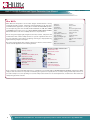
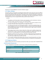
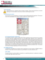
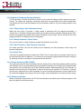
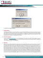
Analog Devices Welcomes
Hittite Microwave Corporation
NO CONTENT ON THE ATTACHED DOCUMENT HAS CHANGED
www.analog.com
www.hittite.com
THIS PAGE INTENTIONALLY LEFT BLANK
Synthesized Signal Generator, 10 MHz to 20 GHz
HMC-T2100
125790 Rev C - 02.0110
Analog & Mixed-Signal ICs, Modules, Subsystems & Instrumentation
User Manual
Installation, Operation & Maintenance Guide
for HMC-T2100 & HMC-T2100B
Order On-Line at: www.hittite.com
Receive the latest product releases - click on “My Subscription”
20 Alpha Road Chelmsford, MA 01824
Phone: 978-250-3343 • Fax: 978-250-3373 • [email protected]
Rev C - 02.0110
HMC-T2100(B) Synthesized Signal Generator User Manual
WHAT WE DO
Hittite Microwave Corporation is an innovative designer and manufacturer of analog
and mixed-signal ICs, modules, subsystems and instrumentation for RF, microwave
and millimeterwave applications covering DC to 110 GHz. Our RFIC/MMIC products
are developed using state-of-the-art GaAs, GaN, InGaP/GaAs, InP, SOI, SiGe, CMOS
and BiCMOS semiconductor processes utilizing MESFET, HEMT, pHEMT, mHEMT,
HBT and PIN devices. We offer over 800 products across 25 product lines:
We also design and supply highly integrated custom ICs, modules, subsystems and
instrumentation that combine multiple functions for specific requirements. We select
the most appropriate semiconductor and package technologies, uniquely balancing
digital and analog integration techniques.
Our custom and standard products support a wide range of wireless / wired communications and radar applications for the following markets:
Automotive
Amplifi ers
Passives
Attenuators
Phase Shifters
Comparators
Data Converters
DROs
Filters - Tunable
Freq. Dividers & Detectors
Freq. Multipliers
High Speed Digital Logic
Limiting Amplifi ers
Interface
Mixers
Mods. & Demodulators
PLLs
PLLs w/ Integrated VCOs
Power Conditioning
Power Detectors
Sensors
Signal Generators
Switches
Transimpedance Amplifi ers
VGAs
VCOs & PLOs
Telematics & Sensors
Microwave & mmWave Communications
Backhaul Radio Links
Multi-Pt Radios & VSAT
Broadband
Military
CATV, DBS, WiBro,WiMAX, WLAN,
Fixed Wireless & UWB
C3I, ECM & EW
Cellular Infrastructure
Space
GSM, GPRS, CDMA, WCDMA,
UMTS, TD-SCDMA & 4G/LTE
Payload Electronics
Fiber Optic
Test & Measurement
OC-48 to 100G
Commercial / Industrial
Sensors & Test Equipment
Every component is backed by Hittite Microwave’s commitment to total quality. HMC is ISO 9001:2000 and AS9100 B certified. Every Hittite
employee and subcontractor is responsible for maintaining the highest level of quality. We are constantly working towards improvement of our
procedures and processes, thus providing our customers with products that meet or exceed all requirements, are delivered on-time and function
reliably throughout their useful life.
2
Order On-Line: www.hittite.com. For technical application questions: Phone: 978-250-3343 or [email protected]
Rev C - 02.0110
HMC-T2100(B) Synthesized Signal Generator User Manual
Table of Contents
1.
Introduction. . . . . . . . . . . . . . . . . . . . . . . . . . . . . . . . . . . . . . . . . . . . . . . . . . . . . . . . . . . . . . . . . . . . . . . . . . . . . . . . 4
2.
Package Contents . . . . . . . . . . . . . . . . . . . . . . . . . . . . . . . . . . . . . . . . . . . . . . . . . . . . . . . . . . . . . . . . . . . . . . . . . . 4
3.
General Overview of Instrument Capabilities . . . . . . . . . . . . . . . . . . . . . . . . . . . . . . . . . . . . . . . . . . . . . . . . . 5
4.
Installation of Equipment and Safety . . . . . . . . . . . . . . . . . . . . . . . . . . . . . . . . . . . . . . . . . . . . . . . . . . . . . . . . 5
5.
Operation and Setup . . . . . . . . . . . . . . . . . . . . . . . . . . . . . . . . . . . . . . . . . . . . . . . . . . . . . . . . . . . . . . . . . . . . . . . 7
6.
Maintenance . . . . . . . . . . . . . . . . . . . . . . . . . . . . . . . . . . . . . . . . . . . . . . . . . . . . . . . . . . . . . . . . . . . . . . . . . . . . . . 21
7.
Programming . . . . . . . . . . . . . . . . . . . . . . . . . . . . . . . . . . . . . . . . . . . . . . . . . . . . . . . . . . . . . . . . . . . . . . . . . . . . . 24
8.
Technical Support . . . . . . . . . . . . . . . . . . . . . . . . . . . . . . . . . . . . . . . . . . . . . . . . . . . . . . . . . . . . . . . . . . . . . . . . . 24
9.
Warranty . . . . . . . . . . . . . . . . . . . . . . . . . . . . . . . . . . . . . . . . . . . . . . . . . . . . . . . . . . . . . . . . . . . . . . . . . . . . . . . . . . 24
10.
Appendix . . . . . . . . . . . . . . . . . . . . . . . . . . . . . . . . . . . . . . . . . . . . . . . . . . . . . . . . . . . . . . . . . . . . . . . . . . . . . . . . . 25
Notice
Hittite Microwave Corporation has prepared this manual for use by Hittite personnel and customers as a
guide for the proper installation, operation, and maintenance of Hittite equipment and computer programs.
The drawings, specifications, and information contained herein are the property of Hittite Microwave Corporation, and any unauthorized use or disclosure of these drawings, specifications, and information is prohibited;
they shall not be reproduced, copied, or used in whole or in part as the basis for manufacture or sale of the
equipment or software programs without the prior written consent of Hittite Microwave Corporation.
Order On-Line: www.hittite.com. For technical application questions: Phone: 978-250-3343 or [email protected]
3
Rev C - 02.0110
HMC-T2100(B) Synthesized Signal Generator User Manual
1. Introduction
This User’s Manual describes the HMC-T2100 10 MHz to 20 GHz Synthesized Signal Generator unit (SG).
Most of the pertinent information can be quickly located through the table of contents and highlighted sections.
The following conventions and indicators are used in this user’s guide:
This indicator calls attention to critical or important information, concerning an operation or
maintenance procedure or practice, which if not strictly followed and observed, could potentially
result in serious injury to operating personnel. An example is the proximity of high AC line voltage.
This indicator draws attention to a situation relating to the equipment set-up, operating or
maintaining the equipment, which if not observed, could result in permanent damage to sensitive
microwave devices or other electronic components.
This indicator highlights a required equipment preparation, fundamental procedure, practice,
condition or statement. Other indicators in bold Blue capital lettering emphasize important points
of information, input or output connections and signal generator specification headings.
The following nomenclature is affixed to the signal generator front and back panels:
HITTITE MODEL NUMBER: HMC-T2100 four-digit alphanumeric, front panel.
This user’s guide should be thoroughly read in depth and reviewed again completely before
attempting to unpack, install or operate the SG unit.
2. Package Contents
The SG unit and packaging material weigh approximately 8 lbs. Before unpacking, check for any
physical damage to the shipping container. If any noticeable damage is observed, immediately
contact Hittite Microwave Corporation. Carefully open the shipping container and inspect the SG
unit for any visible signs of damage. Save the shipping container to repackage the SG unit, or
for submitting necessary damage claims to the transporter. Remove the documentation packet
and any other separately supplied components before attempting to remove the SG unit from the
shipping container. It is highly recommended as a preventative measure, to exercise antistatic
safeguards when handling the SG unit.
Verify that all of the following components are included with the shipment:
Item
Quantity
HMC-T2100 Signal Generator
1
AC Wall Power Supply
1
AC Power Cord
1
CD ROM (Contains User manuals and software)
1
Calibration Certificate
1
HMC-T2100 Quick Start Guide
1
L1-ION Battery Packs (HMC-T2100B only)
2
Table 1: Packing List
4
Order On-Line: www.hittite.com. For technical application questions: Phone: 978-250-3343 or [email protected]
Rev C - 02.0110
HMC-T2100(B) Synthesized Signal Generator User Manual
3. General Overview of Instrument Capabilities
The HMC-T2100 is a single channel frequency synthesizer. The block diagram for this unit is shown in
figure 1. This unit provides one RF output channel with programmable output frequency and output power.
The output frequency range is programmable from 10 MHz to 20 GHz in 10 kHz increments. The synthesizer
provides an internal 10 MHz reference source which can be overridden by an external source. An AC wall
type power supply is provided to generate the required DC power for the unit. The detailed performance
specifications for the synthesizer are listed in the datasheet on the Hittite website.
The user may control the frequency, power, and RF Standby functions from either the Front Panel or the
peripheral interfaces which include a USB, Ethernet and GPIB interface. The RF Standby function will
apply the maximum attenuation to the RF output.
FRONT PANEL
I/O
GPIB
ENET
USB
RS232
SYNTHESIZER
SYNTHESIZER
CONTROLLER
10 MHz - 20 GHz
RF
OUT
USB I/O
CONTROLLER
50 MHz
TCXO
REF
IN
50 MHz
REF
REF
OUT
÷5
PLL
POWER
CONTROL
+12 VDC
HMC-T2100
Figure 1: HMC-T2100 Block Diagram
4. Installation of Equipment and Safety
The guidelines shown below must be followed for proper installation of the SG equipment:
•
The SG equipment was designed for LABORATORY USE ONLY and is not protected against
moisture.
•
Utilize appropriate ESD handling procedures and precautionary measures when installing this
equipment.
•
The SG unit is intended for placement on a laboratory workbench.
•
During install make certain there are no obstructions that would impede air flow to the venting of
the unit on the sides of the enclosure, or the fans located on the rear panel.
•
Ensure that all external components and RF/microwave coaxial cables are in proper condition.
•
A grounded, three pin AC power receptacle should be used to connect power to the AC wall power
supply. It is recommended that the ON/OFF power switch on the front panel be used to interrupt
power to the unit. Interrupting power by pulling out the AC cord may result in injury or unit damage.
Order On-Line: www.hittite.com. For technical application questions: Phone: 978-250-3343 or [email protected]
5
HMC-T2100(B) Synthesized Signal Generator User Manual
Rev C - 02.0110
•
The detachable AC power cord, and the power switch on the front panel must be easily accessible
to facilitate removal of power from the unit.
•
Verify the facility AC line voltage is within specifications before applying power to the unit, or the
applied DC power source is within the specifications of the unit. See paragraph. 5.2.6 to determine
the acceptable input AC voltage, and frequency range.
•
The DC power connector has GND pins which connect to the chassis. Both of these must be
connected to GND for safe operation of the unit.
4.1 Safety Precautions for Lithium Ion Battery Packs (HMC-T2100B)
WARNING:
These safety instructions and the separately provided instructions of the battery manufacturer must be
read carefully and must be fully understood before attempting use. Misusing the battery may cause the
battery to get hot, rupture, ignite, or explode. Be sure to follow all of the safety rules listed below. Failure
to do so may cause serious injury or damage to equipment.
CAUTION
6
•
Use only battery packs supplied by Hittite Microwave Corporation in the HMC-T2100B.
•
Remove batteries when packaging the unit for shipment.
•
Do not place the battery on or near fires, stoves, or other high-temperature locations, as that could
cause the battery to rupture, ignite or explode.
•
Do not install the battery backwards so that the polarity is reversed.
•
Do not connect the positive terminal and the negative terminal of the battery to each other with any
metal object (such as wire), as a short circuit and resulting fire of batter damage may occur.
•
Do not carry or store the batteries together with necklaces, hairpins, or other metal objects, as a
short circuit and resulting fire of batter damage may occur.
•
Do not pierce the battery with nails, strike the battery with a hammer, step on the battery, or otherwise subject it to strong impacts or shocks.
•
Do not solder directly on the battery.
•
Do not expose the battery to water or salt water, or allow the battery to get wet.
•
Do not disassemble or modify the battery. The battery contains safety and protection devices
which, if damaged, may cause the battery to generate heat, rupture or ignite.
•
Do not place the battery in direct sunlight or store the battery inside cars in hot weather. Doing so
may cause the battery to generate heat, rupture, or ignite. Using the battery in this manner may also
result in a loss of performance and a shortened life expectancy.
•
Do not discharge the battery using any device other than the HMC-T2100B synthesized signal
generator. If the battery is used in devices aside from the specified device it may affect the performance of the battery or reduce its life expectancy, and if the device causes an abnormal current to
flow, it may cause the battery to become hot, rupture, or ignite and cause serious injury.
•
Always keep the battery pack out of reach of infants or small children.
Order On-Line: www.hittite.com. For technical application questions: Phone: 978-250-3343 or [email protected]
Rev C - 02.0110
HMC-T2100(B) Synthesized Signal Generator User Manual
•
Do not place the battery in microwave ovens, high-pressure containers, or on induction cookware,
as this could cause the battery to get hot, rupture, ignite or explode.
•
In the event that the battery leaks and the fluid get into one’s eye, do not rub the eye. Rinse well
with water and immediately seek medical care. If left untreated the battery fluid could cause damage to the eye.
•
Use of the battery outside the specified devices operating temperature range may damage the performance of the battery or may reduce its life expectancy.
•
When charging the battery, use only the HMC-T2100B or a specified battery charger ensuring that
the battery charging conditions specified are met.
•
Do not attach the battery to a power supply plug or directly to a car’s cigarette lighter.
•
Do not continue charging the battery if it does not recharge within the specified charging time. Doing so may cause the battery to become hot, rupture, or ignite.
•
The temperature range over which the battery can be charged is +5°C to +35°C. Charging the battery at temperatures outside of this range may cause the battery to become hot or to break. Charging the battery outside of this temperature range may also harm the performance of the battery or
reduce the battery’s life expectancy.
•
Immediately discontinue use of the battery if, while using, charging, or storing the battery, the battery emits an unusual smell, feels hot, changes color, changes shape, or appears abnormal in any
other way.
•
Never dispose of used battery packs with other solid wastes, since they contain toxic substances.
Always dispose of used battery packs in accordance with the prevailing community regulations that
apply to the disposal of batteries. Cover the metal terminals with insulating tape in order to prevent
accidental short-circuiting, and hence possible heating and fire, when disposing of the battery.
5. Operation and Setup
The SG unit control features and setup are detailed in this section.
5.1 Equipment Setup and Operation
Before the SG unit can be operated, external coaxial cables, equipment and instrumentation are
required to be set-up. The instruction steps listed below must first be completed:
1. Use appropriate ESD precautions when connecting cabling, and external equipment to the HMC-T2100
Signal Generator.
2. Verify that the front panel power switch is switched to the “OFF” (Button not depressed) position.
3. Connect DC power cable to rear panel (DIN style DC power connector).
4. Ensure that the ON/OFF switch on the AC power adapter is in the OFF position.
5. Connect the AC power cable to an appropriate 3 prong AC receptacle.
6. Place the ON/OFF switch on the AC power adapter in the ON position. The LED indicator located on
the adapter should be illuminated green in this condition.
7. Connect the RF output to the peripheral equipment using an SMA compatible connector.
Order On-Line: www.hittite.com. For technical application questions: Phone: 978-250-3343 or [email protected]
7
HMC-T2100(B) Synthesized Signal Generator User Manual
Rev C - 02.0110
8. If desired, connect the USB, GPIB, or Ethernet connectors to the Host PC or equivalent.
9. If desired, connect the appropriate BNC connectors to external equipment to provide an external 10
MHz reference.
10. If desired, connect the 10 MHz reference input to external equipment.
11. Press the front panel power switch to the “ON” (labeled 1) position.
12. It is recommended that the user allows a minimum of 30 minutes warm-up time before using the
instrument.
13. Verify the unit is powered on by monitoring the front panel LCD display.
14. Using either the Front Panel Controls or the peripheral interfaces, control the operation of the SG.
5.2 Hardware Interfaces
The front panel of the unit contains a multi-function rotary knob, an RF Standby switch, power On/Off
switch, LCD display, and the connector for the RF output. See figure 2 for a view of the front panel. The
rear panel of the unit contains the connectors for the External Reference Input, Reference Output, DC
power, GPIB, Ethernet, and USB interface. See figure 3 for a view of the rear panel.
Figure 2: Front Panel view of the HMC-T2100
Figure 3: Rear Panel view of the HMC-T2100
8
Order On-Line: www.hittite.com. For technical application questions: Phone: 978-250-3343 or [email protected]
Rev C - 02.0110
HMC-T2100(B) Synthesized Signal Generator User Manual
5.2.1 RF Output Standby
The RF output is delivered via an SMA connector located on the front panel. The RF output may be
commanded to the Standby State by either the RF Standby switch on the front panel, or by commanding
the unit via one of the peripheral interfaces. When in the Standby State, the output power attenuators are
set for maximum attenuation. The RF output specifications are located in the data sheet on the Hittite
website. Please note that while the SG unit is in the Stand-by state, there is still a minimal level of RF
power at the signal generator RF output.
5.2.2
Front Panel Rotary Control Knob
The large rotary knob on the front panel is used to control the synthesizer’s frequency and power output.
When the knob is depressed it will cycle through its functions. The functions consist of the following:
1. Increment/Decrement frequency with 10 KHz steps
2. Increment/Decrement frequency with 100 KHz steps
3. Increment/Decrement frequency with 1 MHz steps
4. Increment/Decrement frequency with 10 MHz steps
5. Increment/Decrement frequency with 100 MHz steps
6. Increment/Decrement frequency with 1 GHz steps
7. Increment/Decrement Output Power with 0.1 dB steps
8. Increment/Decrement Output Power with 1.0 dB steps
Rotation of the knob will increment or decrement the synthesizer’s selected function.
Note: When the front panel controls have been locked out due to computer commands via one of
the peripheral interfaces, the rotary knob may be depressed for ~1.5 seconds to re-enable front panel
controls, and disable computer controls.
5.2.2.1 Setting Synthesizer GPIB Address
If unit is in the Remote mode, press and hold front panel rotary knob for ~1.5 seconds to exit the
Remote mode. Then, press and hold front panel rotary knob for ~1.5 seconds to go to the GPIB
address menu. Rotate the knob to select a GPIB address between 0 and 15. Press and hold the
rotary knob for ~1.5 seconds. This will store the selected GPIB address, and then the LCD display will
change to display the unit’s Serial Number, along with Software and Hardware revision information.
Press and hold the rotary knob for ~1.5 seconds to switch to normal operation, and display power and
frequency.
5.2.3 Front Panel LCD Display
At power turn-on the LCD will display the units Serial Number, Model Number, as well as the firmware
revision. Sometime thereafter the LCD will change to display its operational state. The operational state
provides the information listed in the Table below.
Order On-Line: www.hittite.com. For technical application questions: Phone: 978-250-3343 or [email protected]
9
HMC-T2100(B) Synthesized Signal Generator User Manual
Rev C - 02.0110
Function
Units
Comments
Frequency
MHz
Output Frequency
RF Output Power
dBm
Commanded Output Power
RF Status
N/A
Output ON or OFF
Unit Status
N/A
F – Fan failure, RF output disabled
L – PLL loss of lock
R – Remotely controlled via one of the peripheral interfaces.
Reference Source
N/A
INT (Internal) EXT (External)
Selected Function Indicator
N/A
Underlined character indicates whether rotary knob controls
frequency or power, and determines the resolution step size.
RF Power Status
N/A
Blank – Output Power Leveled
UNLVLD – Output Power Un-Leveled
Battery Status (HMC-T2100B only)
N/A
PRSNT
Battery Present
CHRG
Battery Charging
LOW
Battery Low
Table 2: Front Panel Display
5.2.3.1 Front Panel Power Level Status
The HMC-T2100 includes a power level indicator on the Front Panel display which can be monitored
by the user to determine if the output power specified by the user is within the instruments calibrated
output range (See the data sheet). When the instrument is commanded to a Frequency and Power
combination which is beyond the units specified calibration range, the “UNLVLED” indicator will
appear on the display.
Figure 4: HMC-T2100 Un-calibrated output power indicator
5.2.4 Computer Peripheral Interfaces
The synthesizer’s status and programmable functions are identified in the Programmer’s guide document.
5.2.4.1 USB Interface
The USB connector is located on the rear panel. The USB interface is compliant with USB 1.1, and USB
2.0. The mating connector for this unit is a USB Series B plug style connector.
5.2.4.2 Ethernet Interface
10
Order On-Line: www.hittite.com. For technical application questions: Phone: 978-250-3343 or [email protected]
Rev C - 02.0110
HMC-T2100(B) Synthesized Signal Generator User Manual
The Ethernet connector is located on the rear panel. The mating connector is a standard RJ-45 plug style
connector. The Ethernet interface is a 10/100 Base T interface.
5.2.4.3 GPIB Interface
The GPIB connector is located on the real panel. The mating connector is a standard 24 pin male
connector. The GPIB interface is compliant with IEEE 488.2.
5.2.5 External Reference/Internal Reference
5.2.5.1 Internal Reference Out
The HMC-T2100 includes a single precision 10 MHz reference. The internal 10 MHz reference connects
to one of the BNC connectors on the rear panel. The performance of this reference output is specified in
the datasheet on the Hittite website. The internal reference out feeds through the external reference in.
5.2.5.2 External Reference In
The internal reference can be overridden by connecting an external reference to the BNC connector
located on the rear panel. The unit automatically detects and uses the external reference if present.
5.2.6 Power Input
The unit is powered using the supplied AC wall supply.
5.2.6.1 AC Power adapter
The unit will operate from a single phase AC source of 100 to 240 VAC, with a frequency of 47/63 Hz
supplying current of between 1.25 and 0.5A. The internal AC to DC power supply automatically adjusts
to the connected power source. A 110 VAC, USA standard wall type power supply and cable is provided
with this unit. The AC power adapter contains a power switch, and a power on indicator LED.
5.2.6.2 Power On/Off
Power is turned On/Off with the switch located on the front panel of the enclosure.
5.2.7 Battery Unit (HMC-T2100B)
The HMC-T2100B can be fitted with single or dual Lithium-Ion battery packs which make it independent
of an external power source. The unit can be operated for approximately 2 hours with a single battery,
and up to 4 hours with 2 batteries before the battery packs require recharging. Status indicators on
the front panel display monitor the battery status. The battery packs inside the HMC-T2100B will be
charged whenever the external power supply is connected. When powered ON, the unit may be operated
normally while charging the battery packs concurrently. Typical charging time for each battery pack is
approximately 6 hours, and dual batteries are charged concurrently. Battery performance and life will be
affected by temperature and number of recharge cycles
Order On-Line: www.hittite.com. For technical application questions: Phone: 978-250-3343 or [email protected]
11
HMC-T2100(B) Synthesized Signal Generator User Manual
Rev C - 02.0110
5.2.7.1 Safety Summary
Please carefully read and follow all warnings and cautions in this document before handling and operating
the HMC-T2100B and battery packs. Serious injury and equipment failures may occur if the safety
warnings and cautions are not followed.
CAUTION:
Only battery packs supplied by Hittite Microwave Corporation can be used in the HMC-T2100B.
Remove batteries when packaging the unit for shipment.
5.2.7.2 Battery Installation
Disconnect the external power supply cable from the back of the HMC-T2100B.
To install either one or two of the lithium-ion battery packs, simply remove the top cover by loosening
the two captive screws. Prior to installation, battery charge status can be checked by depressing the
red button on the battery pack. A series of four LEDs will indicate the battery charge status. This status
may also be checked in the same manner once installed.
Insert the battery pack(s) into the HMC-T2100B and verify that the battery pack connector fully engages
the HMC-T2100B receptacle connector. Reinstall the cover and tighten the two captive screws. The unit
is now ready to be operated from battery power. If so desired, re-install the external power supply cable.
5.2.7.3 Operating on Battery Power
Operate the HMC-T2100B normally until the battery indicator on the front panel LCD indicates a low
battery warning. You should be able to use the unit for an average of 2 hours, (single battery), or 4 hours,
(dual batteries) when batteries are new without having to recharge. Once the battery low condition occurs,
you should have approximate 5-10 minutes of operation until the internal power monitoring circuitry will
automatically shut down the unit to prevent over discharging the batteries. It is recommended that the
12
Order On-Line: www.hittite.com. For technical application questions: Phone: 978-250-3343 or [email protected]
Rev C - 02.0110
HMC-T2100(B) Synthesized Signal Generator User Manual
batteries be re-charged before the automatic shutdown engages.
5.2.7.4 Battery Charging
The battery pack(s) are charged by connecting the external power supply to the rear of the unit. With the
external power supply turned off, insert the battery(s) into the unit. Turn on the external power supply. Turn
on the unit with the front panel power button. The battery present indicator should be on or the battery
charging indicator will be on it the battery(s) require charging. The battery charging indicator will go off
when the battery(s) are fully charged and the battery present indicator will be on.
NOTES:
1. The battery unit will shut itself off. Under normal operation at the manufacturers minimum
operating voltage, preventing the battery from being discharged.
2. If a battery pack becomes over discharged, or the battery packs internal protection circuits
have been activated, battery charge time may be longer than typical.
3. If a battery pack has been over discharged resulting in a lower than expected voltage, the
battery charging circuit may not turn on when the battery is inserted into the unit while operating
from the external power supply. In this event, the external power supply should be turned off
before inserting the battery(s).
4. The charging circuits include an internal safety timer. Under normal conditions charging time
will be less than 7 hours. In the event that battery charging time is greater than 8 hours, the
battery(s) are considered defective and should replaced and properly disposed.
5. Batteries may be left in the unit at all times. The battery charger will charge and maintain the
battery(s) level as long as the external power supply is on. If the battery pack(s) are left on the
shelf, the battery charge level will reduce over time.
6. As the number of charge and discharge cycles increase, the operating duration from battery
power will reduce. The battery pack should be disposed of to the appropriate recycling agency.
5.2.7.5 Replacement Batteries
Replace batteries with Lithium-Ion batteries purchased from Hittite, part number HMC-T2100B-BATTERY
5.3 Environmental Requirements
The unit is designed to be operated in an environment meeting the following requirements:
Environment Condition
Value
General Usage
Indoors
Temperature
0 to 35 degrees C
Humidity
15% to 95% non-condensing
Altitude
Less than 3000 meters
Table 3: Environmental Operating Conditions
Order On-Line: www.hittite.com. For technical application questions: Phone: 978-250-3343 or [email protected]
13
HMC-T2100(B) Synthesized Signal Generator User Manual
Rev C - 02.0110
5.4 Fan Air Inlets
The unit utilizes fans, mounted on the rear panel for cooling. Please ensure that the fans, and vent
openings are not obstructed or the unit may overheat and damage may result.
5.5 GUI Instrument control
The instrument may be controlled from a computer using the Hittite Supplied GUI application. The features
of the GUI are described in this section. A picture of the GUI is shown in figure 5.
Figure 5: GUI application
5.5.1 Hardware Selection and Control
The application software supports multiple HMC-T2100 synthesizers being connected to the computer
at one time. With the supplied software GUI, only one HMC-T2100 synthesizer can be selected and
controlled from the GUI application at one time. Multiple HMC-T2100’s can be programmed by the user to
be controlled simultaneously. Please refer to section 7.0 herein. The Control Menu may be accessed by
pointing to the GUI and performing a Right Click with the mouse. The functions available from this menu
are ReMap Hardware, Open, Close, Refresh, and Disable Power Checks. The top right pull-down menu
will provide a list of connected T2100 synthesizers after the application has been opened. Some of the
features below may be accessed through the button below the hardware pull-down menu. The function
of this button changes depending on the state of the software.
5.5.2 ReMap Hardware
If synthesizer’s are added to the computer after the application has been opened, the ReMap Hardware
function may be used to force the computer to go and check for any new synthesizer units.
5.5.2.1 Open
The Open function is used to establish a connection to a specified synthesizer. A synthesizer is selected
with the upper right hand pull-down menu.
14
Order On-Line: www.hittite.com. For technical application questions: Phone: 978-250-3343 or [email protected]
Rev C - 02.0110
HMC-T2100(B) Synthesized Signal Generator User Manual
5.5.2.2 Close
The Close function is used to disconnect the currently selected synthesizer. A new synthesizer may then
be selected with the upper right hand pull-down menu, and the Open function.
5.5.2.3 Refresh
Once a synthesizer has been selected with the Open command, the Refresh function may be used
to read the current status of the synthesizer. If the GUI checkbox for Remote and Local Lockout has
not been checked, the Refresh function will read the current status of the unit as commanded via the
synthesizer’s front panel.
5.5.2.4 Disable Power Checks
Within the menu this function may be selected to disable software power level checking.
5.5.3 Synthesizer Selection Menu
This is a pull-down menu at the top right hand side of the GUI. All synthesizers which have been detected
by the software are displayed in this menu. If synthesizers are added to the computer after the application
has been started, use the ReMap Hardware function to force the software to check for other synthesizers.
5.5.4 Remote and Local Lockout
The Remote and Local Lockout feature is enabled by a checkbox available within the GUI. When the
checkbox is selected, computer controlled operation via the USB is enabled. Front panel control of the
unit is disabled. If this checkbox is not selected, the software application will not change any settings
in the synthesizer. However in this state, if the Refresh button is depressed, the current Frequency and
Power fields will be updated with the current settings within the synthesizer.
5.5.5 Frequency Field
When the Remote and Local Lockout checkbox is selected, the Frequency of the synthesizer may be controlled with the text-box. The desired frequency can be either typed into the provided text-box, or either
the up and down arrows on the keyboard, or the GUI field may be used to increment or decrement the
frequency by the amount indicated in the Step box. After a new frequency has been entered, the application attempts to set the synthesizer to the commanded frequency. If for any reason (Example: outside the
calibration range) the unit does not go to the commanded frequency, the field will be highlighted in yellow.
5.5.6 Power field
When the Remote and Local Lockout checkbox is selected, the Power of the synthesizer may be controlled
with the text-box. The desired power can be either typed into the provided text-box, or either the up and
down arrows on the keyboard, or the GUI field may be used to increment or decrement the frequency by
the dBm indicated in the Step box. After a new power level has been entered, the application attempts
to set the synthesizer to the commanded frequency. If for any reason (Example: outside the calibration
range) the unit does not go to the commanded power, the field will be highlighted in yellow.
5.5.7 RF Output On
When the Remote and Local Lockout checkbox is selected, the RF Output On checkbox is used to
enable and disable the RF output of the Signal Generator.
Order On-Line: www.hittite.com. For technical application questions: Phone: 978-250-3343 or [email protected]
15
HMC-T2100(B) Synthesized Signal Generator User Manual
Rev C - 02.0110
5.5.8 Synthesizer Frequency Sweeping Controls
The GUI provides a number of controls to allow the user to perform sweeps of either frequency or power,
or both. The sweep rate, frequency, and power commands are generated by the software application.
The Remote and Local Lockout checkbox must be selected in order for any of the sweep functions to be
enabled.
5.5.8.1 Single Sweep / Start Continuous Sweep
When the start button is pressed, a single sweep is performed with the selected parameters. If
“Continuous” is selected, sweeping runs continuously for the parameters selected. Depressing the “Stop”
button will stop the current sweep. At the normal completion of any sweeps, the unit will remain at the last
programmed (STOP condition) power and frequency.
5.5.8.2 Sweep Frequency / Sweep Power
The user can select to sweep Frequency using the checkboxes on the GUI.
5.5.8.3 Start Frequency / Stop Frequency / Step Size
For sweep operations, the user can select the start frequency, the stop frequency, and the step size
between frequencies.
5.5.8.4 Dwell Time
A text box is provided to enter the value of the “Dwell Time” for each step in the sweep. Valid values for
this field are 0.003 secs to 3600 secs. The value may be entered by typing the desired value or using the
up and down arrows to increment or decrement the time duration.
5.5.9 Thermal Protection (HMC-T2100B)
The synthesizer contains thermal protection features which will shut down the synthesizer while operating
from batteries when it’s operating temperature is exceeded. Once the unit is in the thermal shutdown mode,
unit operation can be restored by one of the following methods. When operating only from batteries, all
batteries must be removed, and replaced, in order to restore normal operation. If AC power is available,
and the unit’s temperature has been reduced to its normal operating temperature, normal operation will
be restored by plugging in the external AC power supply, and cycling power on the external power supply.
5.5.10 Software Installation
When installing the software from the CD follow the directions provided by the installation program. See
below for general installation process.
16
Order On-Line: www.hittite.com. For technical application questions: Phone: 978-250-3343 or [email protected]
Rev C - 02.0110
HMC-T2100(B) Synthesized Signal Generator User Manual
“Continue past any software installation warnings”
Select the desired components with the checkboxes, and select the install button. The default installation recommended.
Select Next.
Order On-Line: www.hittite.com. For technical application questions: Phone: 978-250-3343 or [email protected]
17
HMC-T2100(B) Synthesized Signal Generator User Manual
Rev C - 02.0110
This window will be displayed during the install process. This window shows status of the install.
The software is being installed.
18
Order On-Line: www.hittite.com. For technical application questions: Phone: 978-250-3343 or [email protected]
Rev C - 02.0110
HMC-T2100(B) Synthesized Signal Generator User Manual
Select Close.
Change the install directory if desired, and then select the large button on the top left.
It is recommended that the installation is to the default directory.
Order On-Line: www.hittite.com. For technical application questions: Phone: 978-250-3343 or [email protected]
19
HMC-T2100(B) Synthesized Signal Generator User Manual
Rev C - 02.0110
Select the desired folder name and location, and select whether you want anyone who uses this computer to be able to run
the application. The default folder location is recommended.
Select the Program Group for installation. Hittite is the recommended group.
Select OK.
20
Order On-Line: www.hittite.com. For technical application questions: Phone: 978-250-3343 or [email protected]
Rev C - 02.0110
HMC-T2100(B) Synthesized Signal Generator User Manual
This window displays software installation progress.
Select Close. The installation of all software components is done.
6. Maintenance
The unit should be calibrated every 12 months. The unit is provided with calibration software so that
the user can perform periodic calibrations. The RF output connector should be cleaned as needed.
6.1 External Cleaning
Disconnect the power cable to the unit. Do not use any spray or liquid detergents to clean the
HMC-T2100 unit. These cleaning products typically employ chemicals or degreasers that could enter
the enclosure and damage electronic components. Only use a soft cloth that is slightly dampened
with a mild cleansing agent diluted in water, to clean the main SG enclosure, as well as the front and
back panels.
Order On-Line: www.hittite.com. For technical application questions: Phone: 978-250-3343 or [email protected]
21
HMC-T2100(B) Synthesized Signal Generator User Manual
Rev C - 02.0110
6.2 Instrument Calibration
The instrument is supplied with a Hittite software application to support the calibration of the unit’s
output power. A picture of the GUI is shown in figure 8. The software will provide information related
to the required equipment, and setup for the calibration. It is assumed that the user will perform the
synthesizer calibration with calibrated test equipment. Insure that the synthesizer has been powered
on for at least 30 minute prior to performing the calibration.
6.2.1 Calibration GUI Operation
1. Start the HMC-T2100 calibration software by opening the file: C:\Program Files\LCS\LCS.exe.
2. The following window should appear.
Figure 6: Calibration GUI
3. Select the “Information” button to show calibration system setup, see figure 9 herein.
Figure 7: Calibration Setup
22
Order On-Line: www.hittite.com. For technical application questions: Phone: 978-250-3343 or [email protected]
Rev C - 02.0110
HMC-T2100(B) Synthesized Signal Generator User Manual
4. From the Select Power Meter pull down windows, select the model and GPIB address of the Power
Meter.
5. From the Optional precision attenuator pull down menu, select the amount of attenuation between at
the output of the HMC-T2100 and the Power Meter.
6. Verify power is ON to the HMC-T2100 and select “Initialize T2100” and verify the following window
appears:
Select OK
7. Select Calibrate.
8. The following error and warning messages may appear if the power meter has a channel with no power
sensor connected. Select OK until the Done window appears indicating that Instrument setup has been
verified.
Select OK
Select OK
Order On-Line: www.hittite.com. For technical application questions: Phone: 978-250-3343 or [email protected]
23
HMC-T2100(B) Synthesized Signal Generator User Manual
Rev C - 02.0110
Select OK
9. Select Yes to begin calibration
7. Programming
The enclosed CDROM contains the necessary control software and drivers to support a smooth installation
with a Windows XP® operating system. Also included is a Programmer’s Reference Guide which provides
the primary software commands, GUI source codes and C language support that permits customized control
compatible with Labview® or LabWindows® routines.
8. Technical Support
Please contact [email protected] or call 978-250-3343 and request the HMC-T2100 technical support
department. Hittite Microwave provides local direct support in many areas around the world. Please see
the “Contact Us” page at www.hittite.com.
9. Warranty
Seller warrants to Buyer that Seller’s standard product instrumentation goods delivered hereunder will conform
to the applicable specifications and certifications and be free of defects in material and workmanship for a
period of one (1) year from the date of shipment to the Buyer. The warranties stated herein are in lieu of all
other warranties, expressed, implied, or statutory and of all other obligations or liabilities on the part of Seller.
Buyer expressly waives any right, claim, or cause of action that might otherwise arise out of the purchase
and use of seller’s products or service. Seller shall not be liable for special or consequential damages of any
nature with respect to any merchandise or service sold, delivered, or rendered No product is warranted to be
fit for any particular use or application, and no warranty is made that any set of standards will be met other
than what is marked on the product. Seller warrants all parts of merchandise of its manufacture to be free
24
Order On-Line: www.hittite.com. For technical application questions: Phone: 978-250-3343 or [email protected]
Rev C - 02.0110
HMC-T2100(B) Synthesized Signal Generator User Manual
from defects caused by faulty material or poor workmanship. Liability is limited to the obligation to repair, or,
to replace without charge Ex-Works Chelmsford, MA any part found to be defective under normal use and
service within the warranty period provided: (1) Seller is promptly notified within the warranty period in writing
upon discovery or such defects; (2) the original product is returned to Seller with Seller’s prior authorization,
transportation charges prepaid; and (3) Seller’s examination shall disclose to its satisfaction that such defects
have not been caused by abuse after delivery. Seller reserves the right to impose a reasonable charge on
Buyer for evaluation and repair of returned goods under certain conditions. The full text of the instrumentation
warranty and returns warranty can be found in the on-line Hittite Microwave Terms and Conditions of Sale
http://www.hittite.com/content/documents/terms.pdf
10. Appendix
Please see the HMC-T2100 specification sheet for further information.
Order On-Line: www.hittite.com. For technical application questions: Phone: 978-250-3343 or [email protected]
25
SALES CONTACT INFORMATION:
Hittite Microwave Worldwide Sales Offices
Hittite Microwave Corporation
USA Corporate Headquarters
Phone: 978-250-3343
Fax: 978-250-3373
[email protected]
Eastern North America
Phone: 978-337-1226
[email protected]
Central (North) North America
Phone: 312-485-8730
[email protected]
Central (South) North America
Phone: 978-808-0652
[email protected]
Western North America
Phone: 817-727-7146
[email protected]
Mexico & South America
Phone: 978-250-3343 x1250
[email protected]
Republic of Korea
Hittite Microwave Asia Co., Limited
Phone: +82-2559-0638
Fax: +82-2559-0639
[email protected]
Western & Southern Europe
Hittite Microwave Europe Limited
Phone: +44-870-7664355
Fax: +978-250-3373
[email protected]
Japan
Hittite KK
Phone: +81-3-6853-6654
[email protected]
Peoples Republic of China
Hittite Microwave Co., Limited
Shanghai Office
Phone: +86-21-6209-8809
Fax: +86-21-6209-6730
[email protected]
Northern Europe
Hittite Microwave Europe Limited
Phone: +44-870-7664355
Fax: +978-250-3373
[email protected]
Shenzhen Office
Phone: +86-755-3322-2116
Fax: +86-755-3322-2117
[email protected]
Central & Eastern Europe
Hittite Microwave Deutschland GmbH
Phone: +49-8031-97654
Fax: +49-8031-98883
[email protected]
Instrumentation Sales Representatives
North America
Europe, Mid-East & Africa
Asia & South Pacific
CT, MA, ME, E. PA, NH,
So. NJ, RI & VT:
GTEK, LLC
(Instrumentation Only)
978-692-4954
Finland & Sweden:
RF Partner AB
+46-31-475100
Japan:
TX:
Testech Inc.
972-644-5010
Farad
+82-3-5261-3091
France:
MB Electronique
+33-1-39-67-67-67
Greece:
Vector Technologies LTD
+30-210-68-58-008
Turkey:
Spark Olcum Teknolojileri Ltd. S
+90 (312) 466 821
Order On-Line at: www.hittite.com
Receive the latest product releases - click on “My Subscription”
20 Alpha Road Chelmsford, MA 01824
Phone: 978-250-3343 • Fax: 978-250-3373 • [email protected]