1
LABORATORY MANUAL
ELEC 199
Laboratory in Engineering Fundamentals
This manual was prepared by:
Adam Zielinski
Adam Zielinski © November 2001
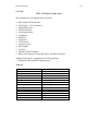
Contents
Acknowledgement
1. Introduction
1.1 Justification and Motivation
1.2 Calendar Description
1.3 Course Implementation
2. Mechanical Fundamentals
2.1 Basic ideas
2.2 Exercises
3. Electronic Fundamentals
3.1 Basic ideas and components
3.2 Exercises
4. Microcontroller Fundamentals
4.1 Basic ideas
4.2 STAMP microcontroller
4.3 Interfacing to the LCD
4.4 Exercises
5. Projects
5.1 Project 1: Force/Sensor Measurements
5.1.1 Beam construction
5.1.2 Force Measurement Principle
5.1.3 Experiments
a) FSR Characteristics
b) Hysteresis of the FSR
c) Mass measurements
5.2 Project 2: Hand gripper exerciser
5.2.1 Principle of Operation
5.2.2 Mechanical Design
5.2.3 Electrical Design
5.2.4 Interfacing with the Microprocessor
5.2.5 Software
5.2.6 Parts
6. Useful references and Internet resources
ELEC 199 Introduction
1.1
Acknowledgement
Funding from UVic Innovative Teaching grant, Cinkant Endowment Fund,
Summer Career Placement Program, and the Department of Electrical and
Computer Engineering was received in support of the development of this
course. Thanks are due to Susumu Kirimura, Mr. Dwayne McLean and Paul
Fedrigo for their involvement. Several other personnel from ECE and Mechanical
Departments were also helpful in the preparation of this course.
1. Introduction
1.1 Justification and Motivation
Students enrolled in the Bachelor of Engineering Programs (Electrical, Computer,
and Mechanical Engineering) come into contact with engineering courses late in
their programs. This situation has undesirable effects:
a) students who are potentially interested in engineering may get
discouraged,
a) some students who are not inclined to engineering discover it too late,
and
a) Students are not given the opportunity to sample different engineering
disciplines before making their decision on which program to choose.
In the past, the Faculty considered a new, general engineering course for the First
Year students. However, it was not implemented primarily because of the lack
of resources and a suitable textbook. ELEC 199 intends to address this need. Its
introduction is expected to enhance our programs, add to the engineering
design/science components as defined by the accreditation requirements, and
increase CO-OP employability of our junior students.
The advances in electronics, materials, and computer technology make it possible
to accomplish breathtaking tasks such as sending men to the moon, launching
space shuttles, and sending unmanned robots to ocean depths or to other
planets. Modern technology is being used in computer games, musical
instruments, automobiles, house appliances, and in numerous other applications.
The typical key components of systems used in such applications are sensors,
microprocessors, and actuators. A sensor senses a physical variable such as
force, pressure, temperature, or light intensity and converts it into an electrical
quantity such as current or voltage. The latter is called a signal. The signal is
then processed by electronic circuits and often converted into digital form to be
manipulated by a microprocessor or computer. After the processing is done, a
suitable electric signal is used to control actuators such as motors, power
amplifiers, lights, car breaks, and others.
In this course, you, the student, will walk along a similar path. You will start by
getting familiar with basic mechanical, electrical and computer concepts as well
as electrical components and subsystems. You will explore simple sensors that
convert non-electrical quantity such as position or force to electrical quantity
such as resistance or voltage. You will build and test a simple force-to-frequency
ELEC 199 Introduction
1.2
converter and a force-to-voltage converter to be interfaced with a microprocessor. By suitable programming of such a microprocessor diverse tasks can
be accomplished. You will see your design working and find out numerous new
applications for them. We hope that this course will be a fun learning experience
for you.
1.2 Calendar Description (2001-02 Calendar)
ELEC 199 Units: 1 S (0-1.5-1) Laboratory in Engineering Fundamentals
The objective of this course is to introduce students to concepts in electrical,
computer, and mechanical engineering through a practical project to be
undertaken by teams of students. The project will involve mechanical
construction, sensing of mechanical quantity by electrical means, as well as
interfacing to and programming of a simple microcontroller. Students will be
required to acquire suitable components, demonstrate their designs, and write a
report documenting their efforts.
Grading: COM, N or F
1.3 Course Implementation
One faculty member will coordinate the course with the help of several teaching
assistants. A laboratory space with several PC stations to test and to program the
microprocessor will be provided and a suitable technical staff will be assigned to
look after this space. Before the second week of classes, students are to form
groups of threes and acquire the required components and tools. Before starting
the project on the fourth week, students must complete all the required exercises
and pass a multiple-choice test. A test failed is to be repeated within one week.
Before the tenth week, each group must demonstrate the completed project. The
final report documenting designs and findings must be submitted before the end
of classes. The students should select the specific topic and research should be
done using the Internet and other resources. The report should contain
independent research on a suitable sensor, converter or transducer to sense a
non-electrical quantity using electrical means. It should also include suggestions
for interesting future projects. The guidelines on report format can be found at:
http://www.coop.engr.uvic.ca/engrweb/WTR.HTML#ch33
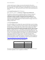
Summary of the tasks is shown in the Table below.
TASKS
Form a group of 3 students
Pass the test
Demonstrate the Designs
Submit the Final Report
When
(weeks in the term)
2
4
10
End of classes
The course will be graded based on the test, demonstration, and the final report
as COM (Completed), N (not Completed) or F (Failed).
ELEC 199 Mechanical Fundamentals
2.1
2. Mechanical Fundamentals
2.1 Basic Ideas
Distance
The distance between two points is measured in meters (m) or kilometers (km).
Motion
An object can move with a velocity (speed) measured in meters per second
(m/s). A car’s speed is usually measured in kilometers per hour (km/h.)
Acceleration
Acceleration is the measure of the increase in velocity in time and is measured in
meters per second over a period of one second or in m/s2. A car that can
accelerate to 60km/h in 6 seconds has an average acceleration of 10 km/s2 or
6000m/s2 .
Mass
Mass is an inherent property of all material objects. It is measured in kilograms
(kg) or grams (g).
Force
Force is a basic mechanical quantity encountered in everyday life. If you want to
move a car, you have to push it with a certain force. The same applies to an
object of a certain mass on the smooth ice surface where, ideally, the object can
move without friction.
The force F needed to speed up an object having a mass m with acceleration a is
given by Newton’s Law:
F= ma
(2.1)
Force is a vector and therefore it has magnitude and direction. The unit of force
is called Newton (N). One Newton (1N) is the force required to accelerate a mass
of 1 kg to 1 m/s2.
Gravity
Objects attract (pull) each other with a certain force. On a planet, this attraction
demonstrates itself as a gravitational force that pulls down an object with a force
proportional to its mass.
F = gm
(2.2)
ELEC 199 Mechanical Fundamentals
2.2
The proportionality constant on Earth g = 9.81 m/ s2. The constant g for other
planets is different. Mass can be measured by measuring the force of gravity also
called a weight. An instrument to measure weight is called a scale. Not
recommended but a convenient measure of force is a force by which a mass of 1
kg is pulled by the gravitational force on Earth. This unit of force is called a
kilogram-force (kgf). Using eq. (2.2) we note that: 1 kgf = 9.81 N. The gravity
force is distributed over all volume of the object however for many situations it is
sufficient to model this force as one vector attached at the center of gravity of the
object.
Pressure
Force F applied over a certain area S exercises a pressure P given by:
P = F/S
(2.3)
Pressure is measured in Pascals. One Pascal is the pressure exercised by one
Newton of force applied to a surface of 1m2. Not a recommended measure of
pressure is one atmosphere (atm) that is 1 kgf applied over 1 cm2 area.
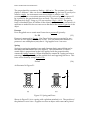
Spring
Springs (or springing members) are made from an elastic material that can be
reversibly deformed under the force applied. This deformation, if within a
certain limit, is proportional to the force applied with the proportionality
constant k (spring constant). When deformed by amount d, a spring exercises a
restoring force F equal to that of the applied force and opposing that force. This
force can be found by using Hook’s Law
F = kd
(2.4)
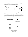
As illustrated in Figure 2.1.
0
(a)
m
0
d
(b)
Figure 2.1 Spring and Force
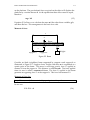
Shown in Figure 2.1(a) is a spring with a platform attached to it. The position of
the platform is set to zero. Suppose now that an object with a mass m is placed
ELEC 199 Mechanical Fundamentals
2.3
on the platform. The gravitational force exercised on the object will displace the
platform by a certain amount d. At the equilibrium these forces must be equal,
therefore:
mg = kd
(2.5)
Equation (2.5) allows us to calculate the mass m if the other three variables g, k,
and d are known. This arrangement is the basis for a scale.
Moment of force
l2
F1
Beam
F2
l1
Support a
Support b
m Weight
Figure 2.2 Beam
Consider an ideal (weightless) beam supported by support-a and support-b as
illustrated in Figure 2.2. Suppose that a weight with mass m is suspended at a
certain point of the beam. This mass is exercising gravity force F2 applied at
distance l 2 from the support a. This distance is called an arm. The force applied
times its arm is called a moment of force. The force F2 applied to the beam
generates an opposing force F1 at the support b. This force has moment F1l1.
Moments of force law
In equilibrium, sum of all moments (with proper sign) must be equal to zero.
In our case:
F1l1 - F2l2 = 0
(2.6)
ELEC 199 Mechanical Fundamentals
2.4
Torque
M
F
d
Figure 2.3 Rotating body
Moment of force applied to a rotating body is called a torque. Torque applied to
a wrench shown in Figure 2.3 is given by d x F.
2.2 Exercises
The exercises must cover all the material in Section 2 and be useful for designs
described in Sections 5.1 and 5.2.
Exercise 1. Compare pressures exercised by the foot of an elephant with that of a
person on high heels. Assume reasonable parameters.
Exercise 2
Exercise 3
Exercise 4
Exercise 5
ELEC 199 Electronic Fundamentals
3.1
3. Electronic Fundamentals
3.1 Basic ideas and components
Current
Electrons are negatively charged particles. The movement of electrons
constitutes the flow of electric current. The movement of a negative charge in
one direction can be thought of as the movement of a positive charge in the
opposite direction. The direction of the positive charge is the direction of current
flow. You can think of an electric charge as water and of an electric current as
water flowing in a river or a pipe. The water flows in a certain direction – from
the higher ground to the lower ground. The measure of current is ampere (A).
An instrument called ammeter is used to measure the current that must pass
through it.
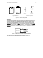
Battery and Voltage
You can think of an electric battery as a generator of a positive charge. Once an
electric load is connected to the battery, the current flows from its positive
terminal (+) to its negative terminal (-) through the connecting wires and the
load. The batteries come with different voltage ratings expressed in volts (V).
For instance, a car battery is a 12-volt battery. The higher the voltage, the more
current will flow from the battery when you connect an electric load to it. You
can think of a battery as a pump, which pumps the water from the lower ground
(usually referenced as zero) to a higher ground. You can think of a battery’s
voltage as the height of the elevated water level. The battery is often called a
voltage source. Voltages are measured by an instrument called a voltmeter. To
measure the voltage, the voltmeter must be connected between two points where
there is a certain voltage difference (like between the + and the - terminals of the
battery). The reference point used to measure voltages is called ground. For
example, one of the terminals of the car battery is connected to the car’s body and
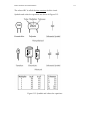
is considered an electric ground. Drawings of batteries and associated symbols
are shown in Figure 3.1.
ELEC 199 Electronic Fundamentals
3.2
+5V
Supply
Battery
Typical Batteries
Ground
Schematic Symbols
Figure 3.1 Batteries and ground
Resistance
Some materials like metals are good conductors of current while some are not.
Electrical connecting wires are made from good conductors (usually copper).
The degree in which a material “resists” the flow of electric current is called
resistance and is measured in ohms. An electronic component called a resistor
has a specific and constant value of its resistance. An instrument called an
ohmmeter measures the resistance placed in its path as illustrated in Figure 3.2.
Ohmmeter
Resistor
R
Figure 3.2 Measure of resistance using an ohmmeter
The symbol and value codes used for resistors are shown in Figure 3.3.
ELEC 199 Electronic Fundamentals
3.3
Figure 3.3 Symbol and code used for the resistors
A multi-meter (or tester) is an instrument that combines the functions of a
voltmeter, an ammeter, and an ohmmeter.
Ohm’s Law
If you connect a battery rated E volts to a resistor R using a wire as shown in
Figure 3.4, a current I will flow through the resistor in the direction as indicated.
The voltage across battery terminals can be measured by voltmeter V, while the
current I through resistor R can be measured by ammeter A.
Voltmeter
V
Ammeter
A
I
Resistor VR
R
Connecting wires
Battery
E
Figure 3.4 Battery connected to a resistor
ELEC 199 Electronic Fundamentals
3.4
The value of current I can be found using a simple relation called Ohm’s Law,
that is:
I = E/R
(3.1)
For instance, if you connect a car cigarette lighter which has R =0.5 ohm
resistance to the car battery rated E =12 volts, the resulting current I will be
I=12/0.5=24 A. The current needed for a starter motor can reach several
hundreds of Amps.
A current I that flows through a resistor R will develop a voltage drop VR across
it with its direction opposing the flow of current as shown in Figure 3.4. The
opposing direction occurs when sign “+” is facing the current flow arrowhead.
This voltage can be found using Ohm’s Law:
VR = I * R
(3.2)
3
In electronic circuits, we usually use resistors in the range of 10 ohm = 1 kohm
-3
(1k) and current is usually expressed in milliamps (1 mA=10 A)
Because current through a resistor is proportional to the voltage applied, we call
such a resistor a linear resistor. There are also nonlinear resistors (elements)
where dependence between current and voltage applied is a nonlinear function.
An example of such a nonlinear element is a diode that will be described later.
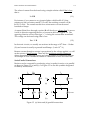
Series/Parallel Connections
Resistors can be connected by conducting wires (or paths) in series or in parallel
as shown in Figure 3.5 (a) and (b). In Figure 3.5 we use the symbols designated
for battery and resistors.
I
R1
E
I
R2
=
E
Rseries
(a)
I
E
I
R1
R2
=
E
(b)
Figure 3.5 (a) Series and (b) parallel connections
Rparallel
ELEC 199 Electronic Fundamentals
3.5
The equivalent resistors will draw the same current I from the battery. Their
value can be calculated as:
R series = R1+R2
R parallel = R1||R2= 1/(1/R1+1/R2)
(3.3)
(3.4)
Voltage Divider
Shown in Figure 3.6(a) is a simple circuit called voltage divider.
I
+E
Implied "-"
connected
to ground
R1
R1
v0
E
R2
v0
(a)
R2
(b)
Figure 3.6 Voltage Divider
The current flowing through both series resistors is given by I = E /(R1+R2).
This current, following Ohm’s law, will cause a voltage drop across the resistor
R2. This voltage drop is given as:
V0 = I*R2 = E*R2/(R1+R2) = E/(1+R1/R2)
(3.5)
By selecting a proper ratio of R1/R2, we can obtain any voltage V0 between zero
and E.
Figure 3.6 (b) shows a simplified way of drawing the circuit shown in Figure
3.6(a). Here we use the symbol “ground” to indicate common connection (or
common node). Any voltage indicated without additional reference information
is taken with respect to the ground.
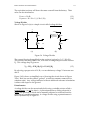
Potentiometer
A voltage divider can be conveniently built using a variable resistor called a
potentiometer (or pot for short). A potentiometer has a sliding electrode (a
wiper), the position of which can be manually adjusted at a desired location
resulting in a variable resistance. A voltage divider using a potentiometer is
shown symbolically in Figure 3.7.
ELEC 199 Electronic Fundamentals
3.6
+5V
Sliding electrode
R1
R
v0
R2
Ground
Figure 3.7 Potentiometer
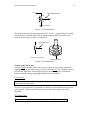
The total resistance of the potentiometer is R = R1+R2. A potentiometer usually
has the form of a round drum with a central rotating shaft that controls the
position of the wiper as shown in Figure 3.8.
Sliding electrode
Schematic Symbol
Sliding electrode
Figure 3.8 Potentiometer
Current and Voltage laws
A circuit node is a point where two or more wires are electrically connected
together. Any closed path along a circuit is called a loop. All voltages directed
in clockwise directions (from negative sign to positive sign) are considered
positive and all voltages opposing that direction are negative.
Current Law:
The sum of all currents flowing into a node must be equal to the sum of all
currents leaving this node.
This law is quite obvious if you think of a node as a point where flowing rivers
(wires) meet. All the water leaving such a junction must equal the water
supplied.
The Voltage law:
The sum of all voltages (with proper sign) along a closed loop is equal to zero.
ELEC 199 Electronic Fundamentals
3.7
This law is obvious if you think of voltage as an elevation. Walking along the
closed loop will always bring you to the starting point with no gain in altitude.
Both current and voltage laws are illustrated in Figure 3.9.
VR1
I1
I
R1
I3
E
R2
VR2
I2
I3 = I1 + I2
(a)
E - VR1 - VR2 = 0
(b)
Figure 3.9 Current and Voltage Laws
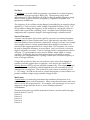
Diodes
A diode is an electrical “valve” that conducts current only in one direction - from
Anode to Cathode as shown in Figure 3.10. A special diode called Light Emitting
Diode (LED) emits light whenever there is current flowing through it. An LED is
often used as an indicator of the voltage presence (LED is “on”) or absence (LED
is “off”).
Anode
Anode
Cathode
Cathode
Schematic Symbol
Diode
Anode
Cathode
Schematic Symbol
LED (Light Emitting Diode)
Figure 3.10 Diodes
ELEC 199 Electronic Fundamentals
3.8
A simple circuit with LED is shown in Figure 3.11.
+5V
1k
I = 5mA
LED
Figure 3.11 LED in action
Capacitor
A capacitor is an electronic device capable of storing the electric charge. This
-6
capacity is measured in units called Farads (F) or µFarads (1µF = 10 F). Once a
capacitor is charged, it will have a certain voltage present between its terminals.
You can think of a capacitor as a water reservoir and the voltage across it as the
water height. When a discharged capacitor (zero voltage across its terminals) is
connected to a voltage source through a resistor as shown in Figure 3.12(a), it
will gradually be charged. The voltage across the capacitor will increase in time
and will eventually reach the voltage supplied to it as illustrated in Figure
3.12(b).
v0(t)
E
R
+E
v0 (t)
C
0
(a)
t
(b)
Figure 3.12 Charging a capacitor
Assuming that the switch S is turned on at time t=0, the voltage on the capacitor
is given by:
V0(t) = E ( 1- e
- t / RC
)
(3.6)
ELEC 199 Electronic Fundamentals
The value of RC is called the time constant for this circuit.
Symbols and codes for capacitors are shown in Figure 3.13.
Figure 3.13 Symbols and values for capacitors
3.9
ELEC 199 Electronic Fundamentals
3.10
Comparator
A comparator is an electronic subsystem that compares two voltages applied to
its inputs as illustrated in Figure 3.14.
+ v1
+ v2
Comparator
+
v0
Figure 3.14 Comparator
The function implemented by a comparator is mathematically described as:
For V2-V1 > 0 we got V0 = High (typically 5 volts)
For V2-V1< 0 we got V0 = Low (typically zero volts)
(3.7)
Figure 3.14 shows an example of a circuit with a comparator using two pots and
an LED. The LED is “on” whenever V1 >V2 and is “off” otherwise.
+5V
+5V
+5V
V1
Compa
rator
V2
LED
Figure 3.15 Comparator with LED indicator.
ELEC 199 Electronic Fundamentals
3.11
Oscillator
An oscillator is a circuit which can generate a waveform at a certain frequency
expressed in cycles per second or Hertz (Hz). The frequency range from
approximately 50 Hz to 20,000 Hz (20 kHz) is called an audible frequency range.
This is because a signal with such a frequency, if applied to a speaker, will
generate an audible tone.
The frequency of an oscillator can be changed (controlled) by an external voltage
applied to it. Such a circuit is called Voltage Controlled Oscillator (VCO). It is
also possible to change the frequency of the oscillator by varying the value of a
resistor that is part of the oscillating circuit. Oscillators are often built using a
comparator and a capacitor charged/discharged through a suitable resistor.
Sensors/Converters
A sensor is an electronic device that typically converts a non-electrical quantity
such as angular or linear displacement, force, light intensity and others into an
electrical quantity such as resistance, capacitance, voltage or current. An example
of an angular sensor is a rotary potentiometer that changes its resistance as a
function of the angular position of its control shaft. This resistance can, in turn,
be used to change the frequency of an oscillator. One can call such a circuit an
angle-to-frequency converter. Used in a voltage divider configuration as shown
in Figure 3.7, a potentiometer can be used to build a simple angle-to-voltage
converter. If changing the pot’s shaft angle requires overcoming a certain
restoring force (say generated by a spring) we then have a force-to-frequency or
force-to-voltage converter.
Using a thin conductive film, one can produce a force sensor that changes its
resistance with the applied force or pressure. Such sensors are called Force
Sensing Resistors (FSR’s) and are available commercially. The resistance of such
a sensor decreases nonlinearly with the applied force and eventually levels off
(saturates) at a certain force. The accuracy of such a sensor is relatively low in
+/- 10% range. An FSR can be used to control the frequency of an oscillator or to
produce variable voltage using a suitable voltage divider.
Multi-meter
A multi-meter is a measuring instrument that combines the functions of an
ammeter, a voltmeter, and an ohmmeter. When using the multi-meter make sure
that it is set for the proper function. For example, you can damage it if you try to
measure a voltage when the device is set for ohmmeter function.
3.2 Exercises
These exercises must cover all the material in Section 3 and be useful in designs
from Sections 5.1 and 5.2
Exercise 1
Exercise 2
Exercise 3
Exercise 4
Exercise 5
ELEC 199 Microcontroller Fundamentals
4.1
4. Microcontroller Fundamentals
4.1 Basic ideas and components
Microcontroller
Most of us know what a computer looks like. It usually has a keyboard, a
monitor, a Central Processing Unit (CPU), a printer, and a mouse. These types of
computers, like the Mac or PC, are primarily designed to communicate or
“interface” with humans. But did you know that there are computers all around
us, running programs and quietly doing calculations, not interacting with
humans at all? These computers are in your car, on the airplane, in your kid
brother’s toy, and maybe even inside your hairdryer. We call these devices
microcontrollers. Micro because they are small, and controller because they
control machines, gadgets, whatever. Microcontrollers are designed to be
connected to machines, rather than to people. They are handy because you can
build a machine or device, write programs to control it, and then let it work for
you automatically. In this course we will use the BASIC Stamp II
microcontroller.
Port
A port is a physical connection that allows devices such as a keyboard, mouse,
monitor, printer, etc. to connect to and communicate with a computer. A
computer has serial and parallel ports that differ in their number of pins and the
rules associated for communication. A microcontroller also has ports. These are
often referred to as I/O (Input/Output) pins. An I/O pin has two usable/
known states: a high state or a low state and it can also be floating. A high state
in the digital circuits represents voltage of approximately +5V, and a low state is
approximately 0V (ground). The BASIC Stamp II has 16 I/O pins that can be
used to directly connect (interface) to devices such as switches, LED’s, displays,
potentiometers, etc.
LCD
The acronym LCD stands for Liquid Crystal Display. This device, if connected to
a microcontroller, can display numbers, characters, graphs, etc. Examples of
LCD’s are the screen on your notebook computer, calculator, digital watch, etc.
Software Program
A software program is a list of precise instructions for the microcontroller to
follow. A typical program looks at the inputs, processes them, and uses the
information to decide what the states of the outputs should be.
ELEC 199 Microcontroller Fundamentals
4.2
Programming Language
A programming language is a set of words and rules for combining those words,
like the vocabulary and grammar of a human language. A programming
language is either understood by a microcontroller, or readily converted to a
form that the microcontroller understands. High level programming languages
are available to program such a device. In this course you will use Stamp
Microcontroller which uses BASIC programming language to implement diverse
operations.
Memory
A software program is stored in memory. The microcontroller reads from or
writes into this memory. Some computers store the software program on an
Electrically Erased Programmable Read Only Memory (or EEPROM). This type
of memory can be programmed many times. The microcontroller fetches one
instruction at a time from memory and performs the appropriate operation on
the input/output pins or internal structures within the microcontroller.
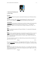
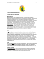
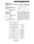
4.2 STAMP
The BASIC Stamp II is one very popular microcontroller. In order for our
microcontroller to function, we need to assemble some hardware. We’ll be using
a pre-assembled Printed Circuit Board (PCB) that contains several parts. Refer to
Figure 4.1 for the block layout of the Stamp Board.
This board was created to simplify connecting “real world stuff” to the BASIC
Stamp. Connectors are provided for the power supply (wall adaptor or 9 volt
battery), the programming cable (serial port) and the Input / Output pins of the
BASIC Stamp. There is also a “prototyping area” or breadboard (the white board
with all the holes in it). You will be using an additional prototype board to build
your circuits on.
Serial
Port
Prototype
Board
BASIC Stamp II
Microcontroller
Memory
(EEPROM)
Power
Supply
Input/Output
Pins
Figure 4.1 Block diagram of Stamp board
We also require a language to program the microcontroller. One of the most
popular languages is called BASIC that stands for Beginner’s All-purpose
Symbolic Instruction Code. The Stamp stores the software program on EEPROM.
ELEC 199 Microcontroller Fundamentals
4.3
To understand how a BASIC program is written, let us look at the program in
Figure 4.2. Anywhere you see the tick mark (‘), the text that follows it (to the end
of the line) is a comment. The computer ignores comments; they provide an
explanation of the program.
The first line in the program that is not a comment is the label loop. Labels serve
two purposes in a BASIC program:
•
•
Like comments, they can provide a hint to the readers about the purpose of a
section of code.
They serve as markers for instructions that change the order in which the
program is carried out.
The command “Goto” tells the program to go back to the beginning of the
program and do some more work. The command “End” tells the computer that
there are no further instructions.
' Access PIC16C7x A/D
loop:
ADCON0 = $45
Pause 1
Serout SO,N2400,[#ADRES,10]
Goto loop
' Start Conversion
' Wait 1ms for conversion
' Send variable to serial out
End
Figure 4.2 Example of BASIC programming
To program the BASIC Stamp II, you plug it into the Board of Education, connect
it to a Windows or Mac computer and run the editor software to create and
download your program via a serial cable. The BASIC Stamp Manual Version
2.0 describes the BASIC command set and can be found on your CD in the Board
of Education folder. Additional information and software is available at:
http://www.stampsinclass.com.
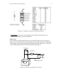
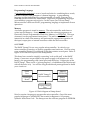
4.3 Interfacing to the LCD
For this course a serial display is used. It is a 2-line by 8-character Liquid Crystal
Display (LCD) module. This unit accepts data transmitted by the Stamp’s
“Serout” instruction. The serial LCD allows you to display text, numbers, and
symbols using simple “Serout” instructions. The display is connected through
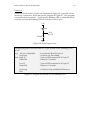
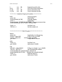
the RS233, 3-pin connector. These pins are connected as illustrated in Figure 4.3.
For further information, refer to the Serial LCD “User Manual – BPI-216 Serial
LCD Modules”.
ELEC 199 Microcontroller Fundamentals
4.4
Pin
===
Symbol
======
Level
====
Function
========
1
2
3
4
5
+5V
GND
SER
GND
+5V
+5V
0V
Pulses
0V
+5V
Positive power pin (Vdd)
Negative power pin (Vss)
Serial data pin
Duplicate negative power pin (Vss)
Duplicate positive power pin (Vdd)
Figure 4.3 Pin connection for the BPI-216 serial LCD module.
4.4 Exercises
Here are a couple of simple BASIC programs that will introduce you to some
programming rules, as well as the BASIC Stamp computer.
Exercise 1
Connect the power adapter cable and serial cable to the Board of Education as
per page 26 of the Basic Stamp Manual on your CD. You may need a DB9 to
DB25 adapter and may have to remove the 2 screws on your serial cable to plug
it into your serial port.
Connect the circuit of Figure 4.4 for this first exercise. This circuit can be
connected on the Stamp II prototype board. Write and run the program of
Figure 4.5. This program will turn the LED on and off every half second.
Port
pin 15
R
2.2k
LED
Figure 4.4 LED output circuit
' Example program to blink an LED connected to I/O pin 15
loop:
High 15
Pause 500
' Turn on LED connected to I/O pin 15
' Delay for .5 seconds
Low 15
Pause 500
' Turn off LED connected to I/O pin 15
' Delay for .5 seconds
Goto loop
End
' Go back to loop and blink LED forever
Figure 4.5 Program will blink an LED
ELEC 199 Microcontroller Fundamentals
4.5
Exercise 2
Connect a switch to the I/O pin 14 as illustrated in Figure 4.6. Leave the circuit
of exercise 1 connected. Write and run the program of Figure 4.7. This program
is a modification of exercise 1. It will turn the blinking LED on when the switch
is closed, and turn the blinking LED off when the switch is open.
+5V
R
10k
Port
pin 14
Switch
Figure 4.6 Switch input circuit
' Example program to read the state of I/O pin 14, and switch a blinking LED
on/off
loop:
if in14 = 0 then blink
Goto loop
blink: High 15
Pause 500
' Is switch on? Read I/O pin 14
' Switch is off ; do nothing
' Turn on LED connected to I/O pin 15
' Delay for .5 seconds
Low 15
Pause 500
' Turn off LED connected to I/O pin 15
' Delay for .5 seconds
Goto loop
End
' Go back to loop and blink LED forever
Figure 4.7 Program will switch on/off a blinking LED
ELEC 199 Projects
5.1
5. Projects
Students must complete, demonstrate, and document two projects described in
Sections 5.1 and 5.2. These projects can be implemented using simple parts and
procedures described in this manual. However, students are encouraged to
incorporate their own ideas and solutions. Students can also propose a new
project but must first seek approval from the course instructor.
5.1 Project 1: Force/Sensor Measurements
5.1.1 Beam Construction
Electrodes
Sensing Element
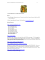
42
Figure 5.1 Force Sensing Resistor (Interlink Electronics)
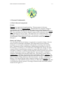
Force Sensing Resistor (FSR)
A Force Sensing Resistor (FSR) will be used for various experiments. The sensor
shown in Figure 5.1 has a sensing element made of a conductive material. Two
electrodes deposited on a plastic sheet are in contact with the material. Applying
a force F to the sensing element decreases the resistance R between the
electrodes. This forces the electrodes into more intimate contact with the
conducting layer. It takes a certain time before this resistance settles. Repeated
measurements with the same applied force yields different values of resistance.
This is due to a certain randomness of the process. Calculating the standard
deviation will determine the accuracy one can expect from this sensor
(approximately ± 10% in our case). The maximum error can also be used as a
measure of accuracy. The FSR characteristics R = f (F) is nonlinear and can be
approximated by a suitable function such as:
R = a + b/ F (a and b are suitable constants)
(5.1)
ELEC 199 Projects
5.2
For forces F in the range of 1 N to 10 N, the resistance R will vary between
several hundred kohms to a few kohms. The FSR shows different characteristics
depending on whether the applied force is increasing or decreasing. This
phenomenon is called hysteresis and is an attribute of most sensors. In order to
minimize the effects of hysteresis, a force must be applied in a consistent manner
that is in a specified direction if at all possible.
i. Scale construction
Platform
Scale
Hinge
Plunger
FSR
Tape
Spacers
Cables
Base
Figure 5.2 Beam-scale
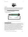
In order to investigate the properties of the FSR sensor you need a suitable
mechanism to apply a force to it. You will build a beam-scale as shown in Figure
5.2. You can use two wooden boards as beams and connect them with a lowfriction hinge. The beam on the bottom is the base while the other is the platform
where test-weights are placed. Include a suitable scale on the platform (mm
resolution) so you can determine the position of the weight. The beams can be
metal or plastic; however, the platform must be stiff enough to support an
applied weight without bending. The platform should not be too heavy, as this
will reduce the force sensing range. Place the FSR on the base, securing it with
Scotch tape. The FSR is pressed by the platform through a suitable round
plunger that covers the face of the sensing element. The material for the plunger
should be elastic so that it will return to its original shape shortly after the force
is released. The material should not be so soft that the applied force deforms it.
A sheet of rubber, plastic foam, vinyl, leather or cork may be suitable. Make sure
that the plunger pushes the FSR uniformly. During series of measurements,
keep FSR under constant pressure of the platform to obtain consistent
measurements. Spacers between the two beams are added in order to make
enough space for the platform to bend slightly under the applied weight. It also
allows for variation of the FSR position by sliding it on the base.
5.3
37
ELEC 199 Projects
Hinge
Mass of the
platform : 90.0 g
Platform
10
6
Plunger
6
6
FSR
Spacer
(50)
Spacer
(movable)
Base
450
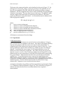
Figure 5.3 Sample dimensions of a beam-scale
The suggested dimensions of the beam-scale (in millimeters) are shown in Figure 5.3.
Figure 5.4 The actual beam-scale
The photograph of an actual design is shown in Figure 5.4
5.1.2 Force Measurement Principle
lw
Weight
Beam
Hinge Fs
mw
mb
mbg
ls
mwg
Sensor
lb
Figure 5.5 A model for beam-scale
ELEC 199 Projects
5.4
The beam scale constructed earlier can be idealized as shown in Figure 5.5. By
placing a known mass mw and by varying its position on the platform we can
vary the force applied to the FSR. Measure the resulting resistance using an
Ohmmeter. The force applied to the sensor can be calculated using the principle
of balance of moments. There are three forces at the beam. The applied weight
and the weight of the beam itself will push down the platform. The sensor
pushes up the beam to keep the balance. As all moments must be balanced, the
following equation applies:
F s ls - m b g l b - m w g l w = 0
(5.2)
where,
Fs : force on sensor (unknown)
ls : distance to center of FSR (measured, known)
lw : distance to center of weight (measured, known)
lb : distance to center of beam mass (measured, known)
mb : mass of platform (measured, known)
mw : mass of weight (known or unknown)
g : gravity constant (known: g= 9.81 m/s2)
All distances are measured from the hinge.
5.1.3 Experiments
a. FSR characteristics
Apply a known weight (mass) at a certain location on the platform. Using eq.
(5.2), calculate the force applied on the sensor. Any object with simple geometry
can serve this purpose since the center of its mass is easily determined. A
cylindrical pile of one-dollar coins may be used (one loonie is about 7g). Coins
can be packed into a plastic film container (6g). Make sure the coins are kept
aligned. Considering the sensor range, it is recommended that you use 20
loonies as a known reference weight, mw = 146 g (they can be put to good use
after the course is over J). Place a reference mass at several locations lw on the
platform and use your multi-meter to read the FSR resistances R corresponding
to a given distance. Measurements must be done several times for the same
applied force. To avoid hysteresis errors, remove the weight before each
measurement and place it again. Convert your data to the applied force F = Fs.
Construct a conversion table, and indicate any errors (standard deviation and/or
maximum errors). Plot the relation between the force F and the average
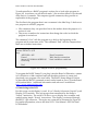
resistance R. Comment on your results and observations.
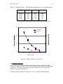
A sample results table using a Microsoft Excel spreadsheet is presented in Table
5.1 – Calibration Table and plotted in Figure 5.6. The vertical bars in Figure 5.6
indicate maximum absolute errors encountered based on n repeated
measurements.
ELEC 199 Projects
5.5
Table 5.1 Calibration Table - FSR resistance against force for n=8 measurements.
lw [m]
Fs [N]
0.000 (*)
0.100
0.200
0.300
0.400
1.99
3.41
4.83
6.25
7.68
Average
R [kohm]
5.45
4.45
3.78
3.43
3.18
Maximum
error [%]
2.69
1.88
0.86
1.31
0.51
(*) no reference mass applied (force is due to mass of platform)
6.0
15
Resistance
Error %
5.0
10
4.0
5
3.0
0
10.0
0.0
2.0
4.0
6.0
8.0
Force F [N]
Figure 5.6 FSR resistance vs. force (n=8)
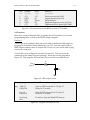
b. Hysteresis of the FSR
Put a weight on the platform at the end close to the hinge, and read the FSR
resistance. Gently slide the weight, without lifting it, and read the corresponding
resistances. Take measurements every 50mm until the end of the platform is
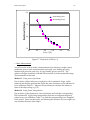
reached. Plot your results R vs. F.
A sample result is presented in Figure 5.7 for n=3 repeated measurements.
ELEC 199 Projects
5.6
6.0
increasing force
decreasing force
5.0
4.0
3.0
0.0
2.0
4.0
6.0
Force F [N]
8.0
10.0
Figure 5.7 Hysteresis of FSR (n=3)
c. Mass Measurement
You will use the scale to make a measurement of an unknown weight (mass),
predict the error of such a measurement and verify your finding by using
another high precision scale (say, at your friendly grocery store J). The
unknown weight should be such that FSR resistance is in the measurable range.
Three methods can be used.
Method 1: Using ratio of positions
Put an object with an unknown weight, but with a symmetric shape, on the
platform and find the position that yields the same resistance as that obtained in
your calibration Table 5.1. Measure this position and calculate the unknown
mass of the object using eq. (5.2).
Method 2: Using linear interpolation
Put an object on the platform at a known distance and read the corresponding
FSR resistance R. Apply linear interpolation between two adjacent reference
points from your calibration Table 5.1 to find the corresponding force F applied
to the sensor. Based on this result, and knowing the distance of your weight, you
can calculate the mass of the object.
ELEC 199 Projects
5.7
Method 3: Global Interpolation
Using equation (5.1) and your calibration Table 5.1 you can find suitable
coefficients a and b. Use this information to link any measured R at a known
distance with applied force F and therefore with the mass of an object.
Try all three methods on 2-3 objects. Discuss the results and comment on your
findings.
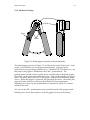
5.2 Project 2: Hand Gripper Exerciser
5.2.1 Principle of Operation
Design task:
Using a commercially available handgrip spring exerciser, design a suitable
exercise monitoring system. The microprocessor should display a number of
hand contractions that exceed a predetermined force level.
Force
Gripper
Angle to
Voltage
Convertor
V1
MicroProcessor
Comparator
Threshold V2
LED
Display
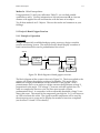
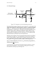
Figure 5.8 Block diagram of hand gripper exerciser
The block diagram of the system is shown in Figure 5.8. The force applied to the
gripper will change the angular position of its handles. This angle can be
monitored using a potentiometer suitably attached to the gripper. Such a
potentiometer serves as an angle-to-voltage converter that generates voltage V1
proportional to the angle. The voltage V1 increases with the applied force. In
order to complete the exercise cycle, the force must exceed a certain
predetermined level. A comparator with an adjustable threshold voltage V2 can
detect this event. The output of the comparator goes high for V1>V2 and turns on
an LED to indicate this event. The signal from the comparator will be used by
the microprocessor to count and to display the number of exercises completed
(see Sections 5.2.4 and 5.2.5 for details).
ELEC 199 Projects
5.8
5.2.2 Mechanical Design
Potentiometer
Shaft
Screw
Plates
Grip angle
Figure 5.9 Hand gripper mounted with potentiometer
The hand grippers, shown in Figure 5.9, will be located in the Project Lab. If you
prefer, you can build your own gripper potentiometer. Grippers can be
purchased at most sporting goods stores (i.e., Canadian Tire, Wal-Mart, etc.). For
this project, the gripper is assembled with a 50kΩ potentiometer. The
potentiometer is fitted with two plastic pieces on either side of the hand gripper.
The plastic can be purchased at hardware store. They can be suitably cut using a
knife. The plastic pieces are fixed to the gripper with small self-threading metal
screws. When the gripper is squeezed, the grip angle decreases. Decreasing this
angle will either increase or decrease the resistance of the potentiometer
depending on which way the potentiometer is mounted or which two of three
terminals are used.
You can use the 50kΩ potentiometer from your kit instead of the gripper while
building your circuit, then replace it with the gripper for your final testing.
ELEC 199 Projects
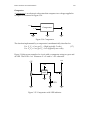
5.9
5.2.3 Electrical Design
+5V
+5V
Hand gripper
R1
with potentiometer 50k
Comparator
LM393
Vsensor 3
+5V
8
Vref 2
4
R2
100k
R4
3.3k
1
Vout
R3
2.2k
LED
Figure 5.10 Comparator circuit for the hand grip exerciser
Squeezing the hand gripper changes the sensor voltage (Vsensor) at the input of the
comparator of Figure 5.10. Resistor R1 represents the potentiometer of the hand
gripper. The comparator outputs a high at Vout when Vsensor reaches the reference
voltage (Vref). This will turn on the LED indicating that the hand gripper has
been squeezed to a certain degree. Adjusting R2 can change the amount of force
needed to light the LED. Comparators usually have what is called an "open
collector" output and require a "pull-up" resistor, R4. When the output is high,
approximately 2V is dropped across R4. This leaves Vout = 3V. Resistor R3 will
limit the maximum current that can pass through the LED.
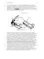
Build the circuit on Figure 5.10 on your prototype board located on your Board
of Education (see Figure 5.11). The Stamp Board is powered by a 9V battery or
by the 9V power adaptor. When the power is properly connected, the “Power
LED” will illuminate. The power supply voltage is reduced from 9V to +5V by a
5V-regulator. 5V supply will be used for circuits on the Prototype Board.
Note: You must connect the +5V wires to Vdd and connect your ground to Vss.
NEVER connect any wires to Vin.
To understand how the prototype board makes internal connections, read the
Board of Education Manual. You can do this by loading the CD, choosing
Documentation, selecting a topic choosing View.
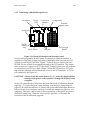
ELEC 199 Projects
5.2.4
5.10
Interfacing with the Microprocessor
9V Battery
Power
LED
6-30V Wall
adapter
Serial port
5V Regulator
External
power pins
Vdd
Vss
J3
J2
J4
J1
BASIC
Stamp
chip
Board of Education
Reset switch
Port pins
Prototype
board
Figure 5.11 Board of Education with Prototype board
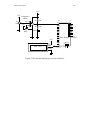
Connect and program the BASIC Stamp II computer to count the number of
repetitions of the hand gripper and connect the display that count on the LCD
(Liquid Crystal Display) module. Figure 5.12 shows how to connect the Basic
STAMP II to the output of the comparator and to the LCD module. The output
of the comparator connects to P15 of the BASIC Stamp II which you will program
to continuously poll P15 for a high voltage. When the LED turns on, P15 goes
high and the computer will increment the count on the LCD module. For LCD
pin connections see Figure 4.3.
CAUTION! Always check the connections to Vdd ,Vss and to the display before
turning on the power so that you don’t damage the display or the
computer.
On the CD, select Board of Education and read the Board of Education Manual
pages 24 – 32. Under the Basic Stamp heading, read the Basic Stamp Manual
pages 25-38 which describe how to connect the serial cable between the Board of
Education and your serial port and how to install the Stampw.exe file onto your
computer. The serial cable is used in the downloading of the BASIC program to
the BASIC Stamp chip. When the reset switch is pressed, it will restart the
execution of the downloaded program.
ELEC 199 Projects
5.11
+5V
+5V
R1
50k
Comparator
LM393
Vsensor
+5V
R4
3.3k
J3
Vref
R3
R2
100k
2.2k
LED
+5V
2X8 LCD
+5
SER
GND
15
14
13
12
11
10
9
8
7
6
5
4
3
2
1
0
J1
5
9
4
8
3
7
2
6
1
toPC
Basic StampII Serial port
Port
pin 0-15
6-30VDC
J2
Vss
Figure 5.12 Complete hand grip exerciser schematic
V in
ELEC 199 Projects
5.12
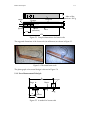
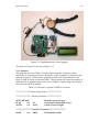
Figure 5.13 Implementation of hand gripper
The photo of Project 2 is shown in Figure 5.13.
5.2.5 Software
The program shown in Table 5.2 can be copied from the computers on the
laboratory or it can be typed into a Windows or Mac computer as directed in the
manual on the CD. This software program is then to be downloaded into the
Basic STAMP II via the 9-pin serial cable. This program will count the number of
times that the comparator goes from a low voltage to a high voltage and display
that count on the LCD module.
Table 5.2 Software to operate STAMP as a counter
'******************** Basic Stamp Project *******************
'********************* Declare Variables ********************
'{$STAMP BS2}
FLAG
var
TOTAL
var
bit
word
'Identifies processor type
'Comparator output high or low?
'Count of lows to highs
'******************* Initialize Constants *******************
N9600
con
$4054
'Set baudrate to 9600
ELEC 199 Projects
I
CLR
L2_C4
L2_C10
con
con
con
con
5.13
254
1
195
202
'Instruction prefix value
'LCD clear-screen instruction
'Line 2, character 4 code
'Line 2, character 10 code
'************* Initialize Display & Variables ***************
INIT:
'Start of program
pause 100
'Small delay
serout 0,N9600, [I,CLR]
'Clear the display
pause 1
'Small delay
serout 0,N9600, ["THREE MUSKETEERS"] 'Insert your names here
serout 0,N9600, [I,L2_C4,"Count:"] 'Dislay Count:
FLAG = 0
TOTAL = 0
'Set FLAG to 0
'Set the counter to 0
'*********************** Main Program ***********************
MAIN:
pause 100
if in15 = 0 then OFF
if in15 = 1 then ON
goto main
OFF:
FLAG = 0
goto MAIN
'Small delay for debouncing
'If P15 is low, go to OFF
'If P15 is high, go to ON
'Loop to MAIN forever
'Set FLAG to 0
'and return to MAIN
ON:
if FLAG = 1 then MAIN
'If flag was already 1, go to MAIN
TOTAL = TOTAL + 1
'else increment the counter
serout 0,n9600, [I,L2_C10]'On line 2, character 10
serout 0,n9600, [dec TOTAL," "]'display the counted decimals
FLAG = 1
'Reset the flag to 1
goto MAIN
'and return to main
ELEC 199 Projects
5.3 Parts
5.14
ELEC 199 Project Course Parts
Parts assembled as a kit (approximate cost $300).
•
•
•
•
•
•
•
•
•
•
•
•
•
•
Basic Stamp II Education Kit
LCD display, 2 X 16 Characters
Digital Multi-meter
50k Potentiometer
100k Potentiometer
Comparator
Red LED
1k Resistor
5.7k Resistor
Long nose pliers
Wire stripper
Tool Box
DB-9M to DB-25F adapter
Beam scale with force sensor FSR-400 by Interlink Electronics
Additional subsystem is supplied by the ECE Department:
• Hand grip with mounted 50k potentiometer
Table 5.3
Component
Hand grip
Comparator IC
LED
Battery
LCD Module
BASIC Stamp II
Potentiometers
Resistors
Capacitors
Force Sensor
Multimeter
Hinge
Wooden Plates
Specifications
LM383N
5mm (Red)
9V
www.stampsinclass.com
www.stampsinclas.com
50kΩ & 100kΩ
Variety
Variety
FSR – Inter-Electronics
Range, M830 BUZ
1" wide
20x3 / 2x1 / 2"
ELEC 199 Useful References and Internet Resources
6.1
6. Useful References and Internet Recourses
Books
1. Scott Edwards, Programming and Customizing the Basic Stamp Computer, McGraw-Hill,
1998, USD34.95
2. Basic Stamp Manual Version 1.9 by Parallax (www.parallaxinc.com)
Internet Sources:
http://www.howstuffworks.com/
· How Car Engines Work
· How Web Pages Work
· How Cell Phones Work
· How CDs Work
· How Jet Engines Work
· How Telephones Work
· How Web Servers Work
· How Diesel Engines Work
· How Television Works
· How Toilets Work
http://www.cln.org/
Welcome to the Community Learning Network WWW home page. CLN is designed to
help K-12 teachers integrate technology into their classrooms. We have over 265 menu
pages with more than 5,800 annotated links to free resources on educational WWW sites
-- all organized within an intuitive structure.
http://www.cln.org/searching_home.html
Search Engines and Subject Directories
http://webhome.idirect.com/~jadams/electronics/,
Welcome! This website allows you to browse the subject of ELECTRONICS. If you are
just starting the journey of learning electronics, I hope you'll make use of the simple
nature and graphical content of this site. Feel free to look around. Don't worry -- there
are no tests at the end of the day.
http://www.cln.org/themes/electronics.html
Electronics (Circuitry) Theme Page
ELEC 199 Useful References and Internet Resources
6.2
Below are the CLN "Theme Pages" which support the study of electricity and electronics
CLN's theme pages are collections of useful Internet educational resources within a
narrow curricular topic and contain links to two types of information. Students and
teachers will find curricular resources (information, content...) to help them learn about
this topic. In addition, there are links to instructional materials (lesson plans) which
will help teachers provide instruction in this theme.
http://ourworld.compuserve.com/homepages/Bill_Bowden/
A small collection of electronic circuits for the hobbyist or student. Site includes 93
circuit diagrams, links to related sites, commercial kits and projects, newsgroups and
educational areas. Most circuits shown here can be built with common components
available from Radio Shack or salvaged from scrap electronic equipment. Almost all of
the circuits have been built and tested and are believed to perform as described.
However, possible mistakes may be found. New items are shown in red color.