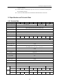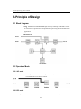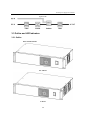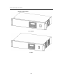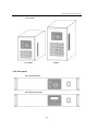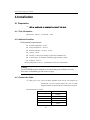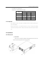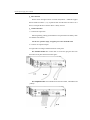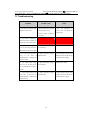
1
TP600SERIES INVERTER POWER SUPPLY USER MANUAL General Instruction This chapter contains important safety and operating instructions. Read and keep this User Guide for later reference. Before using TP600, read and follow all instructions and caution marking on TP600, the batteries, and in all sections of this instruction manual. Contents 1. Important Safety Instruction ............................................................................................................... 1-1 1.1 Safety Instruction .............................................................................................................................. 1-1 1.2 General Precaution ........................................................................................................................... 1-1 1.3 Precaution for battery ....................................................................................................................... 1-1 2. Foreword ............................................................................................................................................... 2-1 2.1 Instruction ......................................................................................................................................... 2-1 2.2 Feature .............................................................................................................................................. 2-1 2.3 Specification and Technical Data...................................................................................................... 2-2 2.3.1 Technical Data ........................................................................................................................ 2-2 2.3.2 DC input voltage and operate range ....................................................................................... 2-3 3. Principle of Design ................................................................................................................................ 3-1 3.1 Block Diagram.................................................................................................................................. 3-1 3.2 Operation Mode ................................................................................................................................ 3-1 3.2.1 AC mode ................................................................................................................................. 3-1 3.2.2 DC mode ................................................................................................................................. 3-1 3.3 Outline and LED Indicators .............................................................................................................. 3-2 3.3.1 Outline .................................................................................................................................... 3-2 3.3.2 Front panel .............................................................................................................................. 3-4 3.3.3 Rear panel ............................................................................................................................... 3-5 3.3.4 LED indicators ........................................................................................................................ 3-6 4. Installation............................................................................................................................................. 4-1 4.1 Preparation ........................................................................................................................................ 4-1 4.1.1 Tool, Information .................................................................................................................... 4-1 4.1.2 Ambient Condition.................................................................................................................. 4-1 4.1.3 Connect the Cable ................................................................................................................... 4-1 4.1.4 Inspection................................................................................................................................ 4-2 4.2 Installation ........................................................................................................................................ 4-2 4.2.1 Rack model ............................................................................................................................. 4-2 -i- 4.2.2 Tower model ........................................................................................................................... 4-4 5. Operation .............................................................................................................................................. 5-1 5.1 Power ON/OFF ................................................................................................................................ 5-1 5.1.1 First power ON ....................................................................................................................... 5-1 5.1.2 General operation ................................................................................................................... 5-1 5.2 Operation .......................................................................................................................................... 5-1 5.2.1 POWER ON ........................................................................................................................... 5-1 5.2.2 Shutdown................................................................................................................................ 5-2 5.2.3 Inaudible ................................................................................................................................. 5-2 6. Operation Mode and Status Display ................................................................................................... 6-1 6.1 LED Indicator and Button Definition ............................................................................................... 6-1 6.2 LCD Interface................................................................................................................................... 6-2 6.3 Work status ....................................................................................................................................... 6-2 6.3.1 Standard model ....................................................................................................................... 6-2 6.3.2 Professional model ................................................................................................................. 6-5 7. Alarm、Remote Control ..................................................................................................................... 7-1 7.1 Alarm signal and Error code description .......................................................................................... 7-1 7.2 Remote control and Alarm ............................................................................................................... 7-2 7.2.1 Communication port ............................................................................................................... 7-2 7.3 Troubleshooting................................................................................................................................ 7-3 -ii- Inverter power supply user’s manual 1.Important Safety Instruction 1.1 Safety Instruction As dangerous voltages and high temperature exist within the INVERTER, only qualified maintenance personnel are permitted to open and repair it. This manual contains information concerning the installation and operation of the TP600。All relevant parts of the manual should be read prior to commencing the installation. Such actions are not warranted as operating against safety requirement or against design, manufacture, safety standard, and are out of the service responsibility. 1.2 General Precaution 1. Do not expose TP600 to rain, snow or liquids of any type,it is designed for indoor use. To reduce risk of damage, do not block off ventilation, or otherwise the INVERTER would be overheating. 2. To avoid fire and electric shock, make sure all cables selected with right gauge and connected well。Smaller diameter and broken cable are not permitted to use. 1.3 Precaution for battery 1. Keep plenty of fresh water and soap at hand in case battery acid contacts skin, clothing, or eyes. 2. NEVER smoke or allow a spark or flame in vicinity of a battery。 3. Do not put the metal tool on the battery; spark and short circuit will lead to explosion. 1-1 Inverter power supply user’s manual 4. Remove personal metal items such as rings, bracelets, necklaces, and watches when working with batteries. Batteries can cause short-circuit current high enough to make metal melt, and could cause severe burns. 1-2 Inverter power supply user’s manual 2.Foreword 2.1 Instruction TP600SERIES INVERTER is designed for DC/AC application especially for high qualify require environment like as communication and electric power field. 2.2 Feature z DSP (Digital Signal Processing) Controller: The DSP monitors the unit output state in real time, and provides excellent transient response comparing to the intelligent program. z PWM+SPWM (Pulse Width Modulation + Switch Pulse Width Modulation): PWM technology is used to supply pure and stable power for 3% distortion and 2% stability pure sine wave. z Advanced isolation technology between DC and AC, meet safety and EMC requirement of system. z Ideal Self-diagnosis function: The DSP is to monitor the system operation. z Automatic Bypass: Under the circumstance of DC input faulty or servicing the battery, the main power will switch to load automatically via the built-in Bypass circuit and the power is supplied by input side directly. z Selectable input frequency ranges 44Hz~66Hz, with output frequency is 50Hz or 60Hz. z Auto restart: When the utility mains reactivation, the unit will restart automatically. z Ideal protection function: When the system is in abnormal condition or other protection mode like Over Current Protection, Over Voltage Protection, Over Power Protection, and Over Temperature Protection, or the components is failure, the DSP will take actions. z Advanced technology of reducing reflected noise, no disturbance to other equipments connected on the same DC distribution frame, multicomplex filtering in AC input to eliminate the utility interference, meeting the requirement for default AC status. z Two operation modes: A and D A) Type A: When AC mains power is normal, unit operates on AC mode. In case AC mains power is abnormal, unit transfer to inverter mode. B) Type D: When DC mains power is normal, unit operates on inverter mode. In case DC mains power is abnormal, unit transfer to AC mode. z Multi-function LED indicators and LCD interface and buzzer alarms. z 3 dry contact provided for alarm of DC input undervoltage, AC input fault, 2-1 Inverter power supply user’s manual equipment faulting. z Standard RS232 communication port: the unit can be controlled and managed by the monitoring software. z Connect external SNMP card to transmit the data between the unit and PC. 2.3 Specification and Technical Data 2.3.1 Technical Data Rating 500VA 1000VA 1500VA 2000VA 3000VA 4000VA 5000VA 4000VA 5000VA Rated DC Input Voltage 48V/110V/220V 110V/220V DC Operating Range 48V/110V/220V -18% ~ 48V/110V/220V +25% Input Reflected Noise Input voltage and load current rated: less than 10% AC Input Voltage 230V-25% ~ 230V+20% Input Frequency 50Hz±10% AC Output Voltage 230V±2% Output Frequency 50Hz±0.1% Rated Output Current 1.7A 3.5A 5.2A 7.0A Power Factor 10.4A 13.9 17.4 48V 13.9 0.8 0.7 THD ≤3% Transient Response Load from 0 to 100%,less than 30ms Bypass Transfer Time <5ms Overload AC mode:120%/3min, 150%/30sec INVERTER mode:120%/30sec, 150%/10sec Efficiency >88% Protection Overload – short circuit – overvoltage – undervoltage – thermal Interface LED+LCD Communication Port RS232 Dry Contact Yes Electric Strength Conform to EN62040-1-1 Noise(1m) ≤45dB Ambient Temperature(℃) -10℃ ~ 45℃ Relative Humidity 0-95% no dew Altitude(m) <1500 482×88×250 W×H×D(mm) 15.2 482×88×330 516×88×320 Rack Weight(Kg) 5.7 6.2 6.5 9 158.5×214.2×461 W×H×D(mm) 9.9 12.5 183.5×293×506 13.5 13.5 14.7 183.5×293×570 Tower Weight(Kg) 7.6 8 8.3 12 2-2 12.9 14 15 14 15 Inverter power supply user’s manual 2.3.2 DC input voltage and operate range Rated voltage 12V 24V 48V 110V 220V Power ON voltage 10.5~14.8 21~29.5 42~59.5 96~136 192~272 DC operated range 10~14.8 20~29.5 40~59.5 91.5~136 183~272 Low warning voltage 11 22 44 101 202 Notes: 1. To protect battery , TP600 only powered ON as battery voltage in DC operated range. 2. When battery voltage is lower to the level of warning point then audible alarm is start up. In case the battery voltage is lower than the limit, unit will shut down. 2-3 Inverter power supply user’s manual 3.Principle of Design 3.1 Block Diagram Note:TP600 based on PWM+SPWM high frequency technology with DSP as control. It is ideal form of protection for all important data processing and telecommunication applications. Block Diagram 3.2 Operation Mode 3.2.1 AC mode That is A operation mode: When mains power is normal, TP600 works in mains mode or inverter mode in case mains is failure. 3.2.2 DC mode That is D operation mode: In ,inverter works all the time in the event of DC failure, unit transfers to 3-1 Inverter power supply user’s manual bypass mode. 3.3 Outline and LED Indicators 3.3.1 Outline Rack standard model 0.5~1.5KVA 2~5KVA 3-2 Inverter power supply user’s manual Rack professional model 0.5~1.5KVA 2~5KVA 3-3 Inverter power supply user’s manual Tower model 0.5~1.5KVA 2~3KVA 3.3.2 Front panel Rack standard model Rack professional model 3-4 Inverter power supply user’s manual Tower model 0.5~1.5KVA 2~3KVA 3.3.3 Rear panel Rack standard model Rack simplified model Rack simplified model 4~5KVA 48V 3-5 Inverter power supply user’s manual Tower model 0.5~1.5KVA 2~3KVA 3.3.4 LED indicators Standard model Professional model 3-6 Inverter power supply user’s manual 4.Installation 4.1 Preparation Only a technician is permitted to install the unit. 4.1.1 Tool, Information Multi-meter、tool box、user manual、cable 4.1.2 Ambient Condition Environment requirements: z Working temperature:0-40℃ z Storage temperature:-40-70℃ z Relative Humidity:0%-95%,no dew z Cooling:nature z Altitude:1500m, meet derating requirements in GB3859.2-93 z Vertical angle:No vibration and hading angle less than 5 degree z Pollution:Class II Working temperature of 20~25 and Humidity of 50% are recommended. Caution The INVERTER must be installed in a location with good ventilation, far away from water, inflammable gas and corrosive agent. 4.1.3 Connect the Cable AC input power cord:Tower and Rack Standard model use the cord prepared by manufacture, but user should prepare the cord for Rack Simplified model and terminal block is installed on rear panel. Recommended size of cable: Rating 500VA Diameter of cable 2 1000VA 0.75mm 2 1mm 1500VA 1.5mm 2 2000VA/3000VA 2.5mm 2 4000VA/5000VA 4 mm 4-1 2 Inverter power supply user’s manual AC output cord:Choose by user DC input cord:Recommended size of cable: Rating Diameter of Cable 110V 220V 48V 2 500VA 2.5 mm 1000VA 4 mm 2 1500VA 6 mm 2 2000VA 10 mm 2 4 mm 3000VA 16 mm 2 6mm 25 mm 2 4000VA/5000VA 1mm 2 2 0. 5mm 1.5 mm 2 1mm 2.5 mm 2 1.5mm 2 2 2.5mm 2 2 2.5mm 2 10mm 2 4 mm 2 2 4.1.4 Inspection Unit should be saved on the right environment and the term for preserving is less than 3months. Before installation, unit should be placed on the spot. Unpack the package and check the package contents. Keep all spare part and accessories for future use. 4.2 Installation 4.2.1 Rack model 1. Install handle Take out two L brackets and handles from packing bag and use M4 to fix them on the left and right sides of unit. Figure as below: 4-2 Inverter power supply user’s manual 2. Place the unit Put the unit on the right location of 19inch rack(Caution:Additional support must be added as bottom!). Try to push the unit from the front and side to see it moves; and repeat the above actions until it is firmly secured.. 3. Cable Connection 1)Connect DC input cable Following battery polarity guide marked on rear panel! Place the battery cable over TP600’s DC terminal. For the user operation safety, cut off the power when install the unit! 2)Connect AC input and output Use right cable according to different terminal of rear panel. For Standard model: take out the cable in accessories, plug the cable into the socket of rear panel showed as follow figure: For Simplified model: use terminal block and notice LINE , NETURAL and polarity: 4-3 Inverter power supply user’s manual 4.2.2 Tower model 1. Fix up Install the unit in any protected environment that provided adequate airflow around the unit, and is free from water. Also, place the unit away from the object at least 20cm around the unit. 2. Cable Connection Refer to Rack Standard Model. Figure as below: 4-4 Inverter power supply user’s manual 5.Operation 5.1 Power ON/OFF 5.1.1 First power ON z Make sure the DC input voltage is according to the symbol on rear panel. Or, DO NOT turn on and unit would be damaged. Consult from manufacture to confirmation. z Inspect the polarity is correct,or unit can not power ON. z Inspect AC input and output is correct, make sure unit is not short-circuited. z Verify above mentioned, open DC and AC power. z Press power ON button: All LEDs illuminate in turn and unit will perform self-diagnosis. Unit is already running in normal mode 5.1.2 General operation z Only press ON/OFF button in daily use. z Power off: loadÆINVERTER. z Cut off the DC and AC input power and output load if long-term no use. z Switch on the unit according to the program of first power on after long-term no use. 5.2 Operation 5.2.1 POWER ON 1. Make sure the DC input and AC output connect is correct; 2. Turn on the unit,unit beeps one time and perform self-diagnosis. 。 note:ON/OFF button located on rear panel for Tower model. Self-diagnosis status: before output is steady, it takes 10ms for DSP to monitor the system operation. When the systems is in abnormal condition or other 5-1 Inverter power supply user’s manual protection mode like Over Current Protection, Over Voltage Protection, Over Power Protection, and Over Temperature Protection, or the component is failure, the DSP will take action to remain its safety. In the mean time, the DSP will show an Error Code on the display. Otherwise, if all parameters are normal, unit will run the normal mode. 5.2.2 Shutdown Press ON/OFF button and inverter LED is winked. 5.2.3 Inaudible In case trouble is shooting during INVERTER is running, unit will alarm with beep and alarm LED will light. Press inaudible button to be inaudible. Press the button continuously for 3sec to turn off the alarm. Alarm will be turned on after press for 3sec again. The original alarm will not beep automatically after inaudible unless other alarm is occurred. 5-2 Inverter power supply user’s manual 6.Operation Mode and Status Display 6.1 LED Indicator and Button Definition LED/Button Symbol Qty Color Status Inaudible 1 Press continually for 3sec to turn ON INAUDIBLE Turn page 1 Change one status interface by pressing once Mains power 1 Green Inverter 1 Blue Bypass 1 Green Output 1 Green Output is normal DC voltage 4 Green ≤25%,≤50%,≤75%,≤100% Load capacity 4 Green ≤25%,≤50%,≤75%,≤100% DC low 1 Yellow It illuminates when DC voltage is lower than limit Overload 1 Yellow It illuminates when load > 100% Troubleshooting 1 Red 6-1 It illuminates when the mains input is normal, flashed when abnormal and goes off when it fails It illuminates when inverter is normal operation It illuminates when unit is on bypass mode It is on in the event of INVERTER faulty Inverter power supply user’s manual 6.2 LCD Interface There are 7 interfaces indicated on LCD: Home page, Working status, Input parameter, Output parameter, running parameter, Parameter inside of unit, Model name. Press Turn page button to change the interface. Home page will be hold in long time no changing interface: 6.3 Work status ●illuminate,◎dim,●flash 6.3.1 Standard model 6.3.1.1 Standby mode In case AC mains input is normal without turning on the unit, the LED indicator of mains power is illuminating, LED indicator of bypass is flashing, and LED indicator of DC shows the capacity. 6-2 Inverter power supply user’s manual 6.3.1.2 AC mode Mains power LED, bypass LED and output LED are illuminating; DC voltage/load show battery capacity and load proportion 6.3.1.3 Inverter mode Inverter LED and output LED are illuminating; DC voltage/load show battery capacity and load proportion 6.3.1.4 DC low Output LED and DC low LED are illuminating; DC voltage/load show battery capacity and load proportion 6-3 Inverter power supply user’s manual AC mode Inverter mode 6.3.1.5 Overload Overload LED is illuminating,in case lighting overload, buzzer beeps once every 2s with normal output. Otherwise, buzzer continually beep without output because of heavy overload and troubleshoot LED is illuminating. Overload on inverter mode Overload on AC mode Shutdown via overload 6.3.1.6 Troubleshooting Troubleshoot LED is illuminating,detailed refer to 7.1 6-4 Inverter power supply user’s manual 6.3.2 Professional model 6.3.2.1 Standby mode In case AC mains input is normal without turning on the unit, the LED indicator of mains power is illuminating, LED indicator of bypass is flashing, press Turn page button to check the parameter. 6.3.2.2 AC mode Bypass LED is illuminating, press Turn page button to check the parameter. 6.3.2.3 Inverter mode Inverter LED is illuminating, press Turn page button to check the parameter. 6-5 Inverter power supply user’s manual 6.3.2.4 DC low Output LED and DC low LED are illuminating; DC voltage/load show battery capacity and load proportion DC low in Inverter mode DC low in AC mode 6.3.2.5 Overload Overload LED is illuminating,in case lighting overload, buzzer beeps once every 2s with normal output. Otherwise, buzzer continually beep without output because of heavy overload and troubleshoot LED is illuminating. 6-6 Inverter power supply user’s manual Overload in AC mode Overload in Inverter mode Overload Shutdown 6.3.2.6 Troubleshooting Troubleshoot LED is illuminating: Shutdown due to overload, DC power on (DC higher voltage), DC power on (inverter faulty), Shutdown due to short-circuited, overheating. See table 7.1 6-7 Inverter power supply user’s manual Alarm via DC higher voltage Alarm due to short-circuit Alarm via inverter faulty Alarm due to Overheating 6-8 Inverter power supply user’s manual Error! Use the Home tab to apply 标题 1 to the text that you want to appear here. Error! Use the Home tab to apply 标题 1 to the text that you want to appear here. 7.Alarm、Remote Control 7.1 Alarm signal and Error code description Trouble Level Trouble Description LED indicator Error Mains Trouble DC Bypass Inverter Output Overload code input shoot lower Beep Output status N/A AC mode (AC and DC are normal) ● ¤ ◎ ◎ ◎ ◎ ◎ N/A N/A NO o/p N/A AC mode(DC is normal) ● ● ◎ ◎ ● ◎ ◎ N/A N/A normal DC mode(DC is normal) Standby mode on AC Note mode(with AC and DC lower voltage) DC power ON Caution (DC voltage is lower than limit) AC power ON Caution (DC voltage is lower than limit) Standby mode on AC Warning mode(with AC and DC higher voltage) AC power ON Warning (DC voltage is higher than limit) AC power ON Warning (overload) DC power ON Warning (overload) DC power ON Troubleshoot (DC voltage is higher than limit) DC power ON Troubleshoot (inverter faulty 1) DC power ON Troubleshoot (inverter faulty 2) × ◎ ● ◎ ● ◎ ◎ N/A N/A normal ● ¤ ◎ ◎ ◎ ● ◎ N/A N/A NO o/p × ◎ ● ◎ ● ● ◎ N/A Once/5s normal ● ● ◎ ◎ ● ● ◎ N/A Once/5s normal ● ¤ ◎ ¤ ◎ ◎ ◎ N/A Once/1s normal ● ● ◎ ¤ ● ◎ ◎ N/A Once/1s normal ● ● ◎ ◎ ● ◎ ● N/A Once/2s normal × ◎ ● ◎ ● ◎ ● N/A Once/2s normal × ◎ ◎ ● ◎ ◎ ◎ 40 Once/1s No o/p × ● ◎ ● ◎ ◎ ◎ 00 Beep continually NO o/p × ● ◎ ● ◎ ◎ ◎ 01 Beep continually NO o/p × ◎ ◎ ● ◎ ◎ ● 04 Beep continually NO o/p NO o/p NO o/p N/A Troubleshoot Shutdown via overload Troubleshoot Shutdown via short-circuit × ◎ ◎ ● ◎ ◎ ◎ 44 Beep continually Troubleshoot Overheating × ◎ ◎ ● ◎ ◎ ◎ 41 Beep continually Note ● ◎ ¤ Illuminating Dim Flash 7-1 Inverter power supply user’s manual × Trouble Level Uncertainty , via the status of mains power, DC voltage and rated load. Herein, Error Code showed by Capacity and load LEDs, for example : 41=4capacity LEDs+1load LED Trouble Level:five class 1.N/A ----- normal 2.Note ----- abnormal but no influence for the operation, unnecessary to take action 3.Caution ----- abnormal and influence the operation of inverter,must be solved 4 . Warning----- abnormal and dangerous, to avoid inverter faulty, must be solved immediately 5.Trouble ----- trouble is shooting and inverter does not operate, must be solved immediately 7.2 Remote control and Alarm 7.2.1 Communication port RS232 Dry contact Dry contact signal: The inverter provides 3 dry contacts (normal open) for alarm with the capacity of 220V and 0.5A 7-2 Inverter power supply user’s manual Error! Use the Home tab to apply 标题 1 to the text that you want to appear here. Error! Use the Home tab to apply 标题 1 to the text that you want to appear here. 7.3 Troubleshooting Condition Possible Cause 1. Unit does not operation after 1. DC/AC cable is not connected Correct 2. DC polarity is wrong DC/AC cable and adjust the the power switch is ON. 3. DC/AC power on voltage is Action the connection of voltage range. out of range 2. Alarm LED is illuminating when unit operates normally, the Error Code is 44 without output 3. AC mode, buzzer beeps once DC input is abnormal, voltage is every 5s, the LED of DC low is lower than limit Adjust the DC voltage illuminating but output is normal 4. AC mode, buzzer beeps once DC input is abnormal, voltage is Dangerous higher voltage would every higher than limit damage inverter, turn off the unit 1s, the LED of Troubleshooting is flashing but and check the DC voltage. output is normal 5. DC mode, buzzer beeps once every 5s, the LED of DC DC input is abnormal, voltage is Adjust the DC voltage lower than limit low is illuminating but output is normal 6. Inverter mode, buzzer beeps DC input is abnormal, voltage is Dangerous higher voltage would once every 1s, the LED of higher than limit damage inverter, turn off the unit Troubleshooting is illuminating and check the DC voltage. without normal 7-3