1
Mellanox MLNX-OS® User Manual
for IBM 90Y3474
Rev 1.6.9
Software Version 3.3.4100
www.mellanox.com
Mellanox Technologies Confidential
Rev 1.6.9
NOTE:
THIS HARDWARE, SOFTWARE OR TEST SUITE PRODUCT (“PRODUCT(S)”) AND ITS RELATED
DOCUMENTATION ARE PROVIDED BY MELLANOX TECHNOLOGIES “AS-IS” WITH ALL FAULTS OF ANY
KIND AND SOLELY FOR THE PURPOSE OF AIDING THE CUSTOMER IN TESTING APPLICATIONS THAT USE
THE PRODUCTS IN DESIGNATED SOLUTIONS. THE CUSTOMER'S MANUFACTURING TEST ENVIRONMENT
HAS NOT MET THE STANDARDS SET BY MELLANOX TECHNOLOGIES TO FULLY QUALIFY THE
PRODUCTO(S) AND/OR THE SYSTEM USING IT. THEREFORE, MELLANOX TECHNOLOGIES CANNOT AND
DOES NOT GUARANTEE OR WARRANT THAT THE PRODUCTS WILL OPERATE WITH THE HIGHEST
QUALITY. ANY EXPRESS OR IMPLIED WARRANTIES, INCLUDING, BUT NOT LIMITED TO, THE IMPLIED
WARRANTIES OF MERCHANTABILITY, FITNESS FOR A PARTICULAR PURPOSE AND NONINFRINGEMENT
ARE DISCLAIMED. IN NO EVENT SHALL MELLANOX BE LIABLE TO CUSTOMER OR ANY THIRD PARTIES
FOR ANY DIRECT, INDIRECT, SPECIAL, EXEMPLARY, OR CONSEQUENTIAL DAMAGES OF ANY KIND
(INCLUDING, BUT NOT LIMITED TO, PAYMENT FOR PROCUREMENT OF SUBSTITUTE GOODS OR SERVICES;
LOSS OF USE, DATA, OR PROFITS; OR BUSINESS INTERRUPTION) HOWEVER CAUSED AND ON ANY
THEORY OF LIABILITY, WHETHER IN CONTRACT, STRICT LIABILITY, OR TORT (INCLUDING NEGLIGENCE
OR OTHERWISE) ARISING IN ANY WAY FROM THE USE OF THE PRODUCT(S) AND RELATED
DOCUMENTATION EVEN IF ADVISED OF THE POSSIBILITY OF SUCH DAMAGE.
Mellanox Technologies
350 Oakmead Parkway Suite 100
Sunnyvale, CA 94085
U.S.A.
www.mellanox.com
Tel: (408) 970-3400
Fax: (408) 970-3403
Mellanox Technologies, Ltd.
Beit Mellanox
PO Box 586 Yokneam 20692
Israel
www.mellanox.com
Tel: +972 (0)74 723 7200
Fax: +972 (0)4 959 3245
© Copyright 2013. Mellanox Technologies. All Rights Reserved.
Mellanox®, Mellanox logo, BridgeX®, ConnectX®, CORE-Direct®, InfiniBridge®, InfiniHost®, InfiniScale®,
MLNX-OS®, PhyX®, SwitchX®, UFM®, Virtual Protocol Interconnect® and Voltaire® are registered trademarks of
Mellanox Technologies, Ltd.
Connect-IB™, ExtendX™, FabricIT™, Mellanox Open Ethernet™, Mellanox Virtual Modular Switch™, MetroX™,
MetroDX™, ScalableHPC™, Unbreakable-Link™ are trademarks of Mellanox Technologies, Ltd.
All other trademarks are property of their respective owners.
2
Document Number: 3956IBM-
Mellanox Technologies
Mellanox Technologies Confidential
Rev 1.6.9
Table of Contents
Document Revision History . . . . . . . . . . . . . . . . . . . . . . . . . . . . . . . . . . . . . . . . . . . . . . . . . 6
About this Manual . . . . . . . . . . . . . . . . . . . . . . . . . . . . . . . . . . . . . . . . . . . . . . . . . . . . . . . . . 7
Intended Audience . . . . . . . . . . . . . . . . . . . . . . . . . . . . . . . . . . . . . . . . . . . . . . . . . . . . . . 7
Related Documentation . . . . . . . . . . . . . . . . . . . . . . . . . . . . . . . . . . . . . . . . . . . . . . . . . . 7
Glossary . . . . . . . . . . . . . . . . . . . . . . . . . . . . . . . . . . . . . . . . . . . . . . . . . . . . . . . . . . . . . . 8
Chapter 1 Introduction . . . . . . . . . . . . . . . . . . . . . . . . . . . . . . . . . . . . . . . . . . . . . . . . . . . 10
1.1
MLNX-OS Features. . . . . . . . . . . . . . . . . . . . . . . . . . . . . . . . . . . . . . . . . . . . . . . 10
Chapter 2 Getting Started . . . . . . . . . . . . . . . . . . . . . . . . . . . . . . . . . . . . . . . . . . . . . . . . . 12
2.1
2.2
2.3
2.4
Configuring the Switch for the First Time . . . . . . . . . . . . . . . . . . . . . . . . . . . . .
Starting the Command Line (CLI). . . . . . . . . . . . . . . . . . . . . . . . . . . . . . . . . . . .
Starting the Web Interface . . . . . . . . . . . . . . . . . . . . . . . . . . . . . . . . . . . . . . . . . .
Licenses . . . . . . . . . . . . . . . . . . . . . . . . . . . . . . . . . . . . . . . . . . . . . . . . . . . . . . . .
12
12
13
15
2.4.1 Installing MLNX-OS® License (CLI) . . . . . . . . . . . . . . . . . . . . . . . . . . . . . . . . . 15
2.4.2 Installing MLNX-OS License (Web) . . . . . . . . . . . . . . . . . . . . . . . . . . . . . . . . . . 16
2.4.3 Retrieving a Lost License Key . . . . . . . . . . . . . . . . . . . . . . . . . . . . . . . . . . . . . . . 18
Chapter 3 User Interfaces . . . . . . . . . . . . . . . . . . . . . . . . . . . . . . . . . . . . . . . . . . . . . . . . . 20
3.1
Command Line Interface (CLI) . . . . . . . . . . . . . . . . . . . . . . . . . . . . . . . . . . . . . . 20
3.1.1
3.1.2
3.1.3
3.1.4
3.1.5
3.1.6
3.2
CLI Modes . . . . . . . . . . . . . . . . . . . . . . . . . . . . . . . . . . . . . . . . . . . . . . . . . . . . . .
Syntax Conventions . . . . . . . . . . . . . . . . . . . . . . . . . . . . . . . . . . . . . . . . . . . . . . .
Getting Help . . . . . . . . . . . . . . . . . . . . . . . . . . . . . . . . . . . . . . . . . . . . . . . . . . . . .
Prompt and Response Conventions. . . . . . . . . . . . . . . . . . . . . . . . . . . . . . . . . . . .
Using the “no” Form . . . . . . . . . . . . . . . . . . . . . . . . . . . . . . . . . . . . . . . . . . . . . . .
Parameter Key . . . . . . . . . . . . . . . . . . . . . . . . . . . . . . . . . . . . . . . . . . . . . . . . . . . .
20
21
21
22
23
24
Web Interface. . . . . . . . . . . . . . . . . . . . . . . . . . . . . . . . . . . . . . . . . . . . . . . . . . . . 25
3.2.1
3.2.2
3.2.3
3.2.4
3.2.5
3.2.6
3.2.7
3.2.8
Setup Menu . . . . . . . . . . . . . . . . . . . . . . . . . . . . . . . . . . . . . . . . . . . . . . . . . . . . . .
System Menu. . . . . . . . . . . . . . . . . . . . . . . . . . . . . . . . . . . . . . . . . . . . . . . . . . . . .
Security Menu . . . . . . . . . . . . . . . . . . . . . . . . . . . . . . . . . . . . . . . . . . . . . . . . . . . .
Ports Menu . . . . . . . . . . . . . . . . . . . . . . . . . . . . . . . . . . . . . . . . . . . . . . . . . . . . . .
Status Menu. . . . . . . . . . . . . . . . . . . . . . . . . . . . . . . . . . . . . . . . . . . . . . . . . . . . . .
IB SM Mgmt . . . . . . . . . . . . . . . . . . . . . . . . . . . . . . . . . . . . . . . . . . . . . . . . . . . . .
Fabric Inspector. . . . . . . . . . . . . . . . . . . . . . . . . . . . . . . . . . . . . . . . . . . . . . . . . . .
ETH Mgmt . . . . . . . . . . . . . . . . . . . . . . . . . . . . . . . . . . . . . . . . . . . . . . . . . . . . . .
26
27
28
28
29
29
30
31
Chapter 4 System Management . . . . . . . . . . . . . . . . . . . . . . . . . . . . . . . . . . . . . . . . . . . . 32
4.1
Management Interface . . . . . . . . . . . . . . . . . . . . . . . . . . . . . . . . . . . . . . . . . . . . . 32
4.1.1
4.1.2
4.1.3
4.1.4
4.1.5
4.2
Configuring Management Interfaces with Static IP Addresses . . . . . . . . . . . . . .
Configuring IPv6 Address on the Management Interface. . . . . . . . . . . . . . . . . . .
Dynamic Host Configuration Protocol (DHCP) . . . . . . . . . . . . . . . . . . . . . . . . . .
Default Gateway . . . . . . . . . . . . . . . . . . . . . . . . . . . . . . . . . . . . . . . . . . . . . . . . . .
In-Band Management . . . . . . . . . . . . . . . . . . . . . . . . . . . . . . . . . . . . . . . . . . . . . .
32
32
32
33
33
Software Management . . . . . . . . . . . . . . . . . . . . . . . . . . . . . . . . . . . . . . . . . . . . . 34
4.2.1 Upgrading MLNX-OS Software - Preconditions . . . . . . . . . . . . . . . . . . . . . . . . . 34
Mellanox Technologies
Mellanox Technologies Confidential
3
Rev 1.6.9
4.2.2
4.2.3
4.2.4
4.2.5
4.3
Upgrading MLNX-OS® Software . . . . . . . . . . . . . . . . . . . . . . . . . . . . . . . . . . . .
Deleting Unused Images . . . . . . . . . . . . . . . . . . . . . . . . . . . . . . . . . . . . . . . . . . . .
Downgrading MLNX-OS Software . . . . . . . . . . . . . . . . . . . . . . . . . . . . . . . . . . .
Upgrading System Firmware . . . . . . . . . . . . . . . . . . . . . . . . . . . . . . . . . . . . . . . .
35
38
39
42
File Management . . . . . . . . . . . . . . . . . . . . . . . . . . . . . . . . . . . . . . . . . . . . . . . . . 43
4.3.1 Saving a Configuration File . . . . . . . . . . . . . . . . . . . . . . . . . . . . . . . . . . . . . . . . . 43
4.3.2 Loading a Configuration File . . . . . . . . . . . . . . . . . . . . . . . . . . . . . . . . . . . . . . . . 43
4.3.3 Restoring Factory Default Configuration on a Switch System
(Single Management Module) 44
4.4
Managing Configuration Files . . . . . . . . . . . . . . . . . . . . . . . . . . . . . . . . . . . . . . . 44
4.4.1 BIN Configuration Files . . . . . . . . . . . . . . . . . . . . . . . . . . . . . . . . . . . . . . . . . . . . 44
4.4.2 Text Configuration Files . . . . . . . . . . . . . . . . . . . . . . . . . . . . . . . . . . . . . . . . . . . . 44
4.5
Logging . . . . . . . . . . . . . . . . . . . . . . . . . . . . . . . . . . . . . . . . . . . . . . . . . . . . . . . . 45
4.5.1 Monitor . . . . . . . . . . . . . . . . . . . . . . . . . . . . . . . . . . . . . . . . . . . . . . . . . . . . . . . . . 45
4.5.2 Remote Logging . . . . . . . . . . . . . . . . . . . . . . . . . . . . . . . . . . . . . . . . . . . . . . . . . . 46
4.6
Event Notifications . . . . . . . . . . . . . . . . . . . . . . . . . . . . . . . . . . . . . . . . . . . . . . . 46
4.6.1
4.6.2
4.6.3
4.6.4
4.7
Supported Events . . . . . . . . . . . . . . . . . . . . . . . . . . . . . . . . . . . . . . . . . . . . . . . . .
SNMP Trap Notifications . . . . . . . . . . . . . . . . . . . . . . . . . . . . . . . . . . . . . . . . . . .
Terminal Notifications . . . . . . . . . . . . . . . . . . . . . . . . . . . . . . . . . . . . . . . . . . . . .
Email Notifications . . . . . . . . . . . . . . . . . . . . . . . . . . . . . . . . . . . . . . . . . . . . . . . .
46
48
48
48
Diagnostics . . . . . . . . . . . . . . . . . . . . . . . . . . . . . . . . . . . . . . . . . . . . . . . . . . . . . 49
4.7.1 Retrieving Return Codes when Executing Remote Commands . . . . . . . . . . . . . . 50
4.8
4.9
mDNS . . . . . . . . . . . . . . . . . . . . . . . . . . . . . . . . . . . . . . . . . . . . . . . . . . . . . . . . . 50
User Management and Security. . . . . . . . . . . . . . . . . . . . . . . . . . . . . . . . . . . . . . 50
4.9.1 Authentication, Authorization and Accounting (AAA) . . . . . . . . . . . . . . . . . . . . 50
4.9.2 Secure Shell (SSH) . . . . . . . . . . . . . . . . . . . . . . . . . . . . . . . . . . . . . . . . . . . . . . . . 52
4.9.3 User Accounts . . . . . . . . . . . . . . . . . . . . . . . . . . . . . . . . . . . . . . . . . . . . . . . . . . . . 53
4.10 Network Management Interfaces. . . . . . . . . . . . . . . . . . . . . . . . . . . . . . . . . . . . . 53
4.10.1 SNMP . . . . . . . . . . . . . . . . . . . . . . . . . . . . . . . . . . . . . . . . . . . . . . . . . . . . . . . . . . 53
4.10.2 MLNX-OS XML API . . . . . . . . . . . . . . . . . . . . . . . . . . . . . . . . . . . . . . . . . . . . . . 59
Chapter 5 Ethernet Switching . . . . . . . . . . . . . . . . . . . . . . . . . . . . . . . . . . . . . . . . . . . . . 60
5.1
5.2
Interface . . . . . . . . . . . . . . . . . . . . . . . . . . . . . . . . . . . . . . . . . . . . . . . . . . . . . . . . 60
Link Aggregation Group (LAG) . . . . . . . . . . . . . . . . . . . . . . . . . . . . . . . . . . . . . 60
5.2.1 Configuring Static Link Aggregation Group (LAG) . . . . . . . . . . . . . . . . . . . . . . 60
5.2.2 Configuring Link Aggregation Control Protocol (LACP) . . . . . . . . . . . . . . . . . . 61
5.3
VLANs. . . . . . . . . . . . . . . . . . . . . . . . . . . . . . . . . . . . . . . . . . . . . . . . . . . . . . . . . 61
5.3.1
5.3.2
5.3.3
5.3.4
5.4
Configuring Access Mode and Assigning Port VLAN ID (PVID). . . . . . . . . . . .
Configuring Hybrid Mode and Assigning Port VLAN ID (PVID). . . . . . . . . . . .
Configuring Trunk Mode VLAN Membership. . . . . . . . . . . . . . . . . . . . . . . . . . .
Configuring Hybrid Mode VLAN Membership . . . . . . . . . . . . . . . . . . . . . . . . . .
62
62
63
63
MAC Address Table . . . . . . . . . . . . . . . . . . . . . . . . . . . . . . . . . . . . . . . . . . . . . . 64
5.4.1 Configuring Unicast Static MAC Address . . . . . . . . . . . . . . . . . . . . . . . . . . . . . . 64
5.5
Spanning Tree . . . . . . . . . . . . . . . . . . . . . . . . . . . . . . . . . . . . . . . . . . . . . . . . . . . 64
5.5.1 Port Priority and Cost . . . . . . . . . . . . . . . . . . . . . . . . . . . . . . . . . . . . . . . . . . . . . . 65
5.5.2 Port Type. . . . . . . . . . . . . . . . . . . . . . . . . . . . . . . . . . . . . . . . . . . . . . . . . . . . . . . . 65
Mellanox Technologies
Mellanox Technologies Confidential
4
Rev 1.6.9
5.5.3 BPDU Filter . . . . . . . . . . . . . . . . . . . . . . . . . . . . . . . . . . . . . . . . . . . . . . . . . . . . . 65
5.5.4 Loop Guard . . . . . . . . . . . . . . . . . . . . . . . . . . . . . . . . . . . . . . . . . . . . . . . . . . . . . . 66
5.5.5 Root Guard . . . . . . . . . . . . . . . . . . . . . . . . . . . . . . . . . . . . . . . . . . . . . . . . . . . . . . 66
5.6
IGMP Snooping . . . . . . . . . . . . . . . . . . . . . . . . . . . . . . . . . . . . . . . . . . . . . . . . . . 66
5.6.1 Configuring IGMP Snooping . . . . . . . . . . . . . . . . . . . . . . . . . . . . . . . . . . . . . . . . 67
5.6.2 Defining a Multicast Router Port on a VLAN . . . . . . . . . . . . . . . . . . . . . . . . . . . 67
5.7
Link Layer Discovery Protocol (LLDP) . . . . . . . . . . . . . . . . . . . . . . . . . . . . . . . 68
5.7.1 Configuring LLDP . . . . . . . . . . . . . . . . . . . . . . . . . . . . . . . . . . . . . . . . . . . . . . . . 68
5.8
Quality of Service (QoS) . . . . . . . . . . . . . . . . . . . . . . . . . . . . . . . . . . . . . . . . . . . 69
5.8.1 Priority Flow Control and Link Level Flow Control . . . . . . . . . . . . . . . . . . . . . . 69
5.8.2 Enhanced Transmission Selection (ETS) . . . . . . . . . . . . . . . . . . . . . . . . . . . . . . . 71
5.9
Access Control List . . . . . . . . . . . . . . . . . . . . . . . . . . . . . . . . . . . . . . . . . . . . . . . 73
5.9.1 Configuring Access Control List . . . . . . . . . . . . . . . . . . . . . . . . . . . . . . . . . . . . . 73
5.9.2 ACL Actions . . . . . . . . . . . . . . . . . . . . . . . . . . . . . . . . . . . . . . . . . . . . . . . . . . . . . 74
5.10 Port Mirroring . . . . . . . . . . . . . . . . . . . . . . . . . . . . . . . . . . . . . . . . . . . . . . . . . . . 74
5.10.1 Mirroring Sessions . . . . . . . . . . . . . . . . . . . . . . . . . . . . . . . . . . . . . . . . . . . . . . . . 75
5.10.2 Configuring Mirroring Sessions . . . . . . . . . . . . . . . . . . . . . . . . . . . . . . . . . . . . . . 78
5.10.3 Verifying Mirroring Sessions . . . . . . . . . . . . . . . . . . . . . . . . . . . . . . . . . . . . . . . . 79
5.11 sFlow . . . . . . . . . . . . . . . . . . . . . . . . . . . . . . . . . . . . . . . . . . . . . . . . . . . . . . . . . . 80
5.11.1
5.11.2
5.11.3
5.11.4
5.11.5
5.11.6
Flow Samples . . . . . . . . . . . . . . . . . . . . . . . . . . . . . . . . . . . . . . . . . . . . . . . . . . . .
Statistical Samples . . . . . . . . . . . . . . . . . . . . . . . . . . . . . . . . . . . . . . . . . . . . . . . .
sFlow Datagrams. . . . . . . . . . . . . . . . . . . . . . . . . . . . . . . . . . . . . . . . . . . . . . . . . .
Sampled Interfaces . . . . . . . . . . . . . . . . . . . . . . . . . . . . . . . . . . . . . . . . . . . . . . . .
Configuring sFlow . . . . . . . . . . . . . . . . . . . . . . . . . . . . . . . . . . . . . . . . . . . . . . . .
Verifying sFlow . . . . . . . . . . . . . . . . . . . . . . . . . . . . . . . . . . . . . . . . . . . . . . . . . .
80
81
81
81
81
82
Mellanox Technologies
Mellanox Technologies Confidential
5
Rev 1.6.9
Document Revision History
Table 1 - Document Revision History - Ethernet
Document
Revision
Date
Changes
Rev 1.6.9
September
2013
Updated Section 4.6, “Event Notifications,” on page 46
Updated Section 4.4.2, “Text Configuration Files,” on page 44
Added Section 4.8, “mDNS,” on page 50
Rev 1.6.8
August 2013
Added Section 4.4.2, “Text Configuration Files,” on page 44
Updated Section 2.4, “Licenses,” on page 15.
Rev 1.6.7
June 2013
Updated Section 6.2.3, “Configuring OSPF,” on page 101.
Updated Section 4.5, “Logging,” on page 45.
Updated Table 19, “Supported Event Notifications and
MIB Mapping,” on page 46.
Rev. 1.6.6
Apr. 2013
Added Section 4.1.5, “In-Band Management,” on page 33.
Added Section 4.6.1, “Supported Events,” on page 46.
Updated Section 5.5, “Spanning Tree,” on page 64.
Rev. 1.6.4
Mar 2013
Added Section 5.10, “Port Mirroring,” on page 74.
Added Section 5.11, “sFlow,” on page 80.
Rev. 1.5.4
Sep. 2012
Updated Section 4.2.4, “Downgrading MLNX-OS Software,”
on page 39.
Rev 1.5.2
June 2012
Updated Section 4.10.1, “SNMP,” on page 53.
Rev 1.5.1
May 2012
Added Section 5.7, “Link Layer Discovery Protocol (LLDP),”
on page 68.
Rev 1.5
May 2012
Initial document.
Mellanox Technologies
Mellanox Technologies Confidential
6
Rev 1.6.9
About this Manual
This manual provides general information concerning the scope and organization of this User’s
Manual.
Intended Audience
This manual is intended for network administrators who are responsible for configuring and
managing Mellanox Technologies’ SwitchX based Switch Platforms.
Related Documentation
The following table lists the documents referenced in this User’s Manual.
Table 2 - Reference Documents
Document Name
Description
InfiniBand Architecture Specification, Vol. 1,
Release 1.2.1
The InfiniBand Architecture Specification that is provided by IBTA.
Switch Installation Guide
Each Mellanox Technologies' switch platform is
shipped with an Installation Guide document to
bring-up and initialize the switch platform.
System Hardware User Manual
This document contains hardware descriptions, LED
assignments and hardware specifications among other
things.
Switch Product Release Notes
Please look up the relevant SwitchX®-based switch
system/series release note file
MLNX-OS® Command Reference Guide
Command Reference Guide for MLNX-OS listing all
of the commands available through MLNX-OS with
explanations and examples.
All of these documents can be found on the Mellanox website. They are available either through
the product pages or through the support page with a login and password.
Mellanox Technologies
Mellanox Technologies Confidential
7
Rev 1.6.9
Glossary
Table 3 - Glossary
AAA
Authentication, Authorization, and Accounting.
Authentication - verifies user credentials (username and password).
Authorization - grants or refuses privileges to a user/client for accessing specific services.
Accounting - tracks network resources consumption by users.
ARP
Address Resolution Protocol. A protocol that translates IP addresses into
MAC addresses for communication over a local area network (LAN).
CLI
Command Line Interface. A user interface in which you type commands at the
prompt
DCB
Data Center Bridging
DCBX
DCBX protocol is an extension of the Link Layer Discovery Protocol
(LLDP). DCBX end points exchange request and acknowledgment messages.
For flexibility, parameters are coded in a type-length-value (TLV) format.
DHCP
The Dynamic Host Configuration Protocol (DHCP) is an automatic configuration protocol used on IP networks.
DNS
Domain Name System. A hierarchical naming system for devices in a computer network
ETS
ETS provides a common management framework for assignment of bandwidth to traffic classes.
FTP/TFTP/sFTP
File Transfer Protocol (FTP) is a standard network protocol used to transfer
files from one host to another over a TCP-based network, such as the Internet.
Gateway
A network node that interfaces with another network using a different network
protocol
HA (High Availability)
A system design protocol that provides redundancy of system components,
thus enables overcoming single or multiple failures in minimal downtime
Host
A computer platform executing an Operating System which may control one
or more network adapters
LACP
Link Aggregation Control Protocol (LACP) provides a method to control the
bundling of several physical ports together to form a single logical channel.
LACP allows a network device to negotiate an automatic bundling of links by
sending LACP packets to the peer (directly connected device that also implements LACP).
LDAP
The Lightweight Directory Access Protocol is an application protocol for
reading and editing directories over an IP network.
MAC
A Media Access Control address (MAC address) is a unique identifier
assigned to network interfaces for communications on the physical network
segment. MAC addresses are used for numerous network technologies and
most IEEE 802 network technologies including Ethernet.
Mellanox Technologies
Mellanox Technologies Confidential
8
Rev 1.6.9
Table 3 - Glossary
MTU (Maximum Transfer Unit)
The maximum size of a packet payload (not including headers) that can be
sent /received from a port
Network Adapter
A hardware device that allows for communication between computers in a
network
PFC/FC
Priority Based Flow Control applies pause functionality to traffic classes OR
classes of service on the Ethernet link.
RADIUS
Remote Authentication Dial In User Service. A networking protocol that
enables AAA centralized management for computers to connect and use a network service.
RDMA (Remote Direct Memory
Access)
Accessing memory in a remote side without involvement of the remote CPU
RSTP
Rapid Spanning Tree Protocol. A spanning-tree protocol used to prevent loops
in bridge configurations. RSTP is not aware of VLANs and blocks ports at the
physical level.
SA (Subnet Administrator)
The interface for querying and manipulating subnet management data
SCP
Secure Copy or SCP is a means of securely transferring computer files
between a local and a remote host or between two remote hosts. It is based on
the Secure Shell (SSH) protocol.
SNMP
Simple Network Management Protocol. A network protocol for the management of a network and the monitoring of network devices and their functions
NTP
Network Time Protocol. A protocol for synchronizing computer clocks in a
network
SSH
Secure Shell. A protocol (program) for securely logging in to and running programs on remote machines across a network. The program authenticates
access to the remote machine and encrypts the transferred information through
the connection.
syslog
A standard for forwarding log messages in an IP network
TACACS+
Terminal Access Controller Access-Control System Plus. A networking protocol that enables access to a network of devices via one or more centralized
servers. TACACS+ provides separate AAA services.
XML Gateway
Extensible Markup Language Gateway. Provides an XML request-response
protocol for setting and retrieving HW management information.
Mellanox Technologies
Mellanox Technologies Confidential
9
Rev 1.6.9
1
Introduction
Mellanox® Operating System (MLNX-OS®) enables the management and configuration of Mellanox Technologies’ SwitchX® silicon based switch platforms. MLNX-OS supports the Virtual
Protocol Interconnect (VPI) technology which enables it to be used for both Ethernet and InfiniBand technology providing the user with greater flexibility.
MLNX-OS provides a full suite of management options, including support for Mellanox’s Unified Fabric Manager® (UFM), SNMP V1,2,3, and web user interface. In addition, it incorporates
a familiar industry-standard CLI, which enables administrators to easily configure and manage
the system.
1.1
MLNX-OS Features
Table 4 - General System Features
Feature
Description
Software Management
•
•
Dual software image
Software and firmware updates
File management
•
•
•
FTP
TFTP
SCP
Logging
•
•
Event history log
SysLog support
Management Interface
•
•
DHCP/Zeroconf
IPv6
Chassis Management
•
Monitoring environmental controls
Network Management Interfaces
•
•
SNMP v1,v2c,v3
REST interfaces (XML Gateway)
Security
•
•
•
•
SSH
Telnet
RADIUS
TACACS+
Date and Time
•
NTP
Cables & Transceivers
•
Transceiver info
Virtual Port Interconnect®
(VPI)
•
•
Ethernet
InfiniBand
Table 5 - Ethernet Features
Feature
General
Description
•
•
•
Jumbo Frames (9K)
ACL - 24K rules (permit/deny)
Breakout cables
Mellanox Technologies
Mellanox Technologies Confidential
10
Rev 1.6.9
Table 5 - Ethernet Features
Feature
Description
Ethernet support
•
•
•
•
•
•
•
•
•
48K Unicast MAC addresses
VLAN (802.1Q) - 4K
LAG/LACP (802.3ad), 16 links per LAG (36 LAGs)
Rapid Spanning Tree (802.1w)
Flow control (802.3x)
IGMP snooping v1,2
LLDP
ETS (802.1Qaz)
PFC (802.1Qbb)
IP routing
•
•
•
VLAN interface
ECMP
OSPF
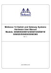
Figure 1: Managing an Ethernet Fabric Using MLNX-OS
Mellanox Technologies
Mellanox Technologies Confidential
11
Rev 1.6.9
2
Getting Started
The procedures described in this chapter assume that you have already installed and powered on
your switch according to the instructions in the Hardware Installation Guide, which was shipped
with the product.
2.1
Configuring the Switch for the First Time
Connect the host PC to the console (mini USB) port of the switch system using the supplied
cable.
Step 1.
Figure 2: Console Ports
.
No remote IP connection is available at this stage via the external management port.
The internal management port can be accessed currently by the chassis management.
Configure a serial terminal with the settings described below.
Step 2.
Table 6 - Serial Terminal Program Configuration
Parameter
Baud Rate
9600
Data bits
8
Stop bits
1
Parity
None
Flow Control
None
Step 3.
2.2
Setting
Login as admin and use admin as password.
Starting the Command Line (CLI)
Step 1.
Set up an Ethernet connection between the switch and a local network machine using a standard RJ-45 connector.
Mellanox Technologies
Mellanox Technologies Confidential
12
Rev 1.6.9
Step 2.
Start a remote secured shell (SSH) to the switch using the command “ssh -l <username>
<switch ip address>.”
rem_mach1 > ssh -l <username> <ip address>
Mellanox MLNX-OS Switch Management
Last login: Thu Apr 28 11:24:13 2011 from 192.168.10.1
Mellanox Switch
switch >
2.3
Step 3.
Login to the switch (default username is admin, password admin)
Step 4.
Once you get the prompt, you are ready to use the system. Refer to MLNX-OS Command Reference Guide for additional information on the CLI commands.
Starting the Web Interface
To start a WebUI connection to the switch platform:
Step 1.
Set up an Ethernet connection between the switch and a local network machine using a standard RJ-45 connector.
Step 2.
Open a web browser – Internet Explorer 7.0 Chrome or Mozilla Firefox 3.0.
Note: Make sure the screen resolution is set to 1024*768 or higher.
Step 3.
Type in the IP address of the switch or its DNS name in the format: http://
<switch_IP_address>.
Step 4.
Login to the switch (default user name is admin, password admin).
The following figure shows an example of the login window for remote management of the
switch.
Mellanox Technologies
Mellanox Technologies Confidential
13
Rev 1.6.9
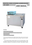
Figure 3: MLNX-OS Login Window
After you log in to MLNX-OS, a (default) status summary window will be displayed containing
the following information:
Figure 4: Display After Login
Mellanox Technologies
Mellanox Technologies Confidential
14
Rev 1.6.9
2.4
Licenses
MLNX-OS software package can be extended with premium features. Installing a license allows
you to access the specified premium features.
This section is relevant only to switch systems with an internal management capability.
The following licenses are offered with MLNX-OS software:
Table 7 - MLNX-OS Licenses
OPN
2.4.1
Valid on product
Description
UPGR-6012-GW
SX6012
Ethernet L2/L3, Gateway
UPGR-6012F-56E
SX6012
56GbE link speed
UPGR-1012-GW
SX1012
InfiniBand, Ethernet L3, Gateway
UPGR-1012-56E
SX1012
56GbE link speed
UPGR-6018-GW
SX6018
Ethernet L2/L3, Gateway
UPGR-6018F-56E
SX6018
56GbE link speed
UPGR-6036-GW
SX6036
Ethernet L2/L3, Gateway
UPGR-6036F-56E
SX6036
56GbE link speed
UPGR-1036-GW
SX1036
InfiniBand, Ethernet L3, Gateway
UPGR-1036F-56E
SX1036
56GbE link speed
UPGR-1024-GW
SX1024
InfiniBand, Ethernet L3, Gateway
UPGR-1024-56E
SX1024
56GbE link speed
LIC-fabric-inspector
SX6036F/T/
SX65XX
InfiniBand fabric inspector monitoring and health.
Installing MLNX-OS® License (CLI)
To install an MLNX-OS license via CLI:
Step 1.
Login as admin and change to Config mode.
switch > enable
switch # config terminal
Step 2.
Install the license using the key. Run:
switch (config) # license install <license key>
Mellanox Technologies
Mellanox Technologies Confidential
15
Rev 1.6.9
Step 3.
Display the installed license(s) using the following command.
switch (config) # show licenses
License 1: <license key>
Feature: EFM_SX
Valid: yes
Active: yes
switch (config) #
Make sure that the “Valid” and “Active” fields both indicate “yes”.
Step 4.
Save the configuration to complete the license installation. Run:
switch (config) # configuration write
If you do not save the installation session, you will lose the license at the next system
start up.
2.4.2
Installing MLNX-OS License (Web)
To install an MLNX-OS license via CLI:
Step 1.
Log in as admin.
Step 2.
Click the Setup tab and then Licensing in the left side navigation pane.
Figure 5: No Licenses Installed
Mellanox Technologies
Mellanox Technologies Confidential
16
Rev 1.6.9
Step 3.
Enter your license key(s) in the text box. If you have more than one license, please enter each
license in a separate line. Click “Add Licenses” after entering the last license key to install
them.
If you wish to add another license key in the future, you can simply enter it in the text
box and click “Add Licenses” to install it.
Figure 6: Enter Licence Key(s) in Text Box
All installed licenses should now be displayed.
Mellanox Technologies
Mellanox Technologies Confidential
17
Rev 1.6.9
Figure 7: Installed License
Step 4.
Save the configuration to complete the license installation.
If you do not save the installation session, you will lose the installed licenses at the
next system boot.
2.4.3
Retrieving a Lost License Key
In case of a lost MLNX-OS® license key, contact your authorized Mellanox reseller and provide
the switch’s chassis serial number.
To obtain the switch’s chassis serial number:
Step 1.
Login to the switch.
Step 2.
Retrieve the switch’s chassis serial number using the command “show inventory”.
switch (config) # show inventory
================================================================================
Module
Type
Part number
Serial Number
================================================================================
CHASSIS
SX1035
MSX6036F-1BFR
MT1121X02692
MGMT
SX1035
MSX6036F-1BFR
MT1121X02692
FAN
SXX0XX_FAN
MSX60-FF
MT1121X02722
PS1
SXX0XX_PS
N/A
N/A
CPU
CPU
SA000103
MT1120X01027
switch (config) #
Mellanox Technologies
Mellanox Technologies Confidential
18
Rev 1.6.9
Step 3.
Send your Mellanox reseller the following information to obtain the license key:
• The chassis serial number
• The type of license you need to retrieve. Refer to “MLNX-OS Licenses” on page 15.
Step 4.
Once you receive the license key, you can install the license as described in the sections above.
Mellanox Technologies
Mellanox Technologies Confidential
19
Rev 1.6.9
3
User Interfaces
3.1
Command Line Interface (CLI)
MLNX-OS® is equipped with an industry-standard CLI. The CLI is accessed through SSH or
Telnet sessions, or directly via the console port on the front panel (if it exists).
Refer to the MLNX-OS Command Reference Guide for complete set of commands, syntax and
examples.
3.1.1
CLI Modes
The CLI can be in one of following modes, and each mode makes available a certain group (or
level) of commands for execution. The different CLI configuration modes are:
Table 8 - CLI Modes and Config Context
Mode/Context
Description
Standard
When the CLI is launched, it begins in Standard mode. This is the
most restrictive mode and only has commands to query a
restricted set of state information. Users cannot take any actions
that directly affect the system, nor can they change any configuration.
Enable
The enable command moves the user to Enable mode. This
mode offers commands to view all state information and take
actions like rebooting the system, but it does not allow any configurations to be changed. Its commands are a superset of those
in Standard mode.
Config
The configure terminal command moves the user from
Enable mode to Config mode. Config mode is allowed only for
user accounts in the “admin” role (or capabilities). This mode has
a full unrestricted set of commands to view anything, take any
action, and change any configuration. Its commands are a superset of those in Enable mode. To return to Enable mode, enter
exit or no configure.
Note that moving directly from/to Standard mode to/from Config
mode is not possible.
Config Interface Management
Configuration mode for management interface mgmt0, mgmt1
and loopback.
Config interface ethernet
Configuration mode for Ethernet interface.
Config Interface Port Channel
Configuration mode for Port channel (LAG).
Config Vlan
Configuration mode for VLAN.
Any Command Mode
Several commands such as “show” can be applied within any
context.
Mellanox Technologies
Mellanox Technologies Confidential
20
Rev 1.6.9
3.1.2
Syntax Conventions
To help you identify the parts of a CLI command, this section explains conventions of presenting
the syntax of commands.
Table 9 - Syntax Conventions
Syntax Convention
Description
Example
< > Angled brackets
Indicate a value/variable that
must be replaced.
<1...65535> or <switch interface>
[ ] Square brackets
Enclose optional parameters.
However, only one parameter out
of the list of parameters listed can
be used. The user cannot have a
combination of the parameters
unless stated otherwise.
[destination-ip | destination-port |
destination-mac]
{ } Braces
Enclose alternatives or variables
that are required for the parameter
in square brackets.
[mode {active | on | passive}]
| Vertical bars
Identify mutually exclusive
choices.
active | on | passive
Do not type the angled or square brackets, vertical bar, or braces in command lines. This
guide uses these symbols only to show the types of entries.
CLI commands and options are in lowercase and are case-sensitive.
For example, when you enter the enable command, enter it all in lowercase. It cannot
be ENABLE or Enable. Text entries you create are also case-sensitive.
3.1.3
Getting Help
You may request context-sensitive help at any time by pressing “?” on the command line. This
will show a list of choices for the word you are on, or a list of top-level commands if you have
not typed anything yet.
For example, if you are in Standard mode and you type “?” at the command line, then you will
get the following list of available commands.
switch > ?
cli
enable
exit
help
no
Configure CLI shell options
Enter enable mode
Log out of the CLI
View description of the interactive help system
Negate or clear certain configuration options
Mellanox Technologies
Mellanox Technologies Confidential
21
Rev 1.6.9
show
Display system configuration or statistics
slogin
Log into another system securely using ssh
switch
Configure switch on system
telnet
Log into another system using telnet
terminal
Set terminal parameters
traceroute
Trace the route packets take to a destination
switch-11a596 [standalone: master] >
If you type a legal string and then press “?” without a space character before it, then you will
either get a description of the command that you have typed so far or the possible command/
parameter completions. If you press “?” after a space character and “<cr>” is shown, this means
that what you have entered so far is a complete command, and that you may press Enter (carriage
return) to execute it.
Try the following to get started:
?
show
show
show
show
show
?
c?
clock?
clock ?
interfaces ?
(from enable mode)
You can also enter “help” to view a description of the interactive help system.
Note also that the CLI supports command and/or parameter tab-completions and their shortened
forms. For example, you can enter “en” instead of the “enable” command, or “cli cl” instead of
“cli clear-history”. In case of ambiguity (more than one completion option is available, that is),
then you can hit double tabs to obtain the disambiguation options. Thus, if you are in Enable
mode and wish to learn which commands start with the letter “c”, type “c” and click twice on the
tab key to get the following:
switch # c<tab>
clear
cli
switch # c
configure
(There are three commands that start with the letter “c”: clear, cli and configure.)
3.1.4
Prompt and Response Conventions
The prompt always begins with the hostname of the system. What follows depends on what command mode the user is in. To demonstrate by example, assuming the machine name is
“switch”, the prompts for each of the modes are:
switch >
switch #
switch (config) #
(Standard mode)
(Enable mode)
(Config mode)
Mellanox Technologies
Mellanox Technologies Confidential
22
Rev 1.6.9
The following session shows how to move between command modes: \
switch
switch
switch
switch
switch
switch
switch
switch
switch
>
> enable
#
# configure terminal
(config) #
(config) # exit
#
# disable
>
(You start in Standard mode)
(Move to Enable mode)
(You are in Enable mode)
(Move to Config mode)
(You are in Config mode)
(Exit Config mode)
(You are back in Enable mode)
(Exit Enable mode)
(You are back in Standard mode)
Commands entered do not print any response and simply show the command prompt after you
press <Enter>.
If an error is encountered in executing a command, the response will begin with “%”, followed by
some text describing the error.
3.1.5
Using the “no” Form
Several Config mode commands offer the negation form using the keyword “no”. This no form
can be used to disable a function, to cancel certain command parameters or options, or to reset a
parameter value to its default. To re-enable a function or to set cancelled command parameters or
options, enter the command without the “no” keyword (with parameter values if necessary).
The following example performs the following:
1. Displays the current CLI session options.
2. Disables auto-logout.
3. Displays the new CLI session options (auto-logout is disabled).
4. Re-enables auto-logout (after 15 minutes).
5. Displays the final CLI session options (auto-logout is enabled)
// 1. Display the current CLI session options
switch (config) # show cli
CLI current session settings:
Maximum line size:
8192
Terminal width:
157 columns
Terminal length:
60 rows
Terminal type:
xterm
Auto-logout:
15 minutes
Paging:
enabled
Progress tracking:
enabled
Prefix modes:
enabled
...
// 2. Disable auto-logout
switch (config) # no cli session auto-logout
// 3. Display the new CLI session options
switch-1 [standalone: master] (config) # show cli
CLI current session settings:
Maximum line size:
8192
Terminal width:
157 columns
Mellanox Technologies
Mellanox Technologies Confidential
23
Rev 1.6.9
Terminal length:
60 rows
Terminal type:
xterm
Auto-logout:
disabled
Paging:
enabled
Progress tracking:
enabled
Prefix modes:
enabled
...
// 4. Re-enable auto-logout after 15 minutes
switch (config) # cli session auto-logout 15
// 5. Display the final CLI session options
switch (config) # show cli
CLI current session settings:
Maximum line size:
8192
Terminal width:
157 columns
Terminal length:
60 rows
Terminal type:
xterm
Auto-logout:
15 minutes
Paging:
enabled
Progress tracking:
enabled
Prefix modes:
enabled
...
3.1.6
Parameter Key
This section provides a key to the meaning and format of all of the angle-bracketed parameters in
all the commands that are listed in this document.
Table 10 - Angled Brackets Parameter Description
Parameter
Description
<domain>
A domain name, e.g. “mellanox.com”.
<hostname>
A hostname, e.g. “switch-1”.
<ifname>
An interface name, e.g. “mgmt0”, “mgmt1”, “lo” (loopback), etc.
<index>
A number to be associated with aliased (secondary) IP addresses.
<IP address>
An IPv4 address, e.g. “192.168.0.1”.
<log level>
A syslog logging severity level. Possible values, from least to most severe, are:
“debug”, “info”, “notice”, “warning”, “error”, “crit”, “alert”, “emerg”.
<GUID>
Globally Unique Identifier. A number that uniquely identifies a device or component.
<MAC address>
A MAC address. The segments may be 8 bits or 16 bits at a time, and may be
delimited by “:” or “.”. So you could say “11:22:33:44:55:66”,
“1122:3344:5566”, “11.22.33.44.55.66”, or “1122.3344.5566”.
<netmask>
A netmask (e.g. “255.255.255.0”) or mask length prefixed with a slash (e.g. “/
24”). These two express the same information in different formats.
Mellanox Technologies
Mellanox Technologies Confidential
24
Rev 1.6.9
Table 10 - Angled Brackets Parameter Description
Parameter
3.2
Description
<network prefix>
An IPv4 network prefix specifying a network. Used in conjunction with a netmask to determine which bits are significant. e.g. “192.168.0.0”.
<regular expression>
An extended regular expression as defined by the “grep” in the man page. (The
value you provide here is passed on to “grep -E”.)
<node id>
ID of a node belonging to a cluster. This is a numerical value greater than zero.
<cluster id>
A string specifying the name of a cluster.
<port>
TCP/UDP port number.
<TCP port>
A TCP port number in the full allowable range [0...65535].
<URL>
A normal URL, using any protocol that wget supports, including http, https, ftp,
sftp, and tftp; or a pseudo-URL specifying an scp file transfer. The scp pseudoURL format is scp://username:password@hostname/path/filename.
Note that the path is an absolute path. Paths relative to the user's home directory
are not currently supported. The implementation of ftp does not support authentication, so use scp or sftp for that.
Note also that if you omit the “:password” part, you may be prompted for the
password in a follow up prompt, where you can type it securely (without the
characters being echoed). This prompt will occur if the “cli default prompt
empty-password” setting is true; otherwise, the CLI will assume you do not want
any password. If you include the “:” character, this will be taken as an explicit
declaration that the password is empty, and you will not be prompted in any case.
Web Interface
MLNX-OS® package equipped with web interface which is a web GUI that accept input and
provide output by generating webpages which can be viewed by the user using a web browser.
The following web browsers are supported
•
Internet Explorer 8.0 or higher
•
Chrome 18 or higher
•
Mozilla Firefox 12 or higher
•
Safari 5 or higher
The web interface makes available the following perspective tabs:
•
Setup
•
System
•
Security
•
Ports
•
Status
•
IB SM Management
•
Fabric Inspector
Mellanox Technologies
Mellanox Technologies Confidential
25
Rev 1.6.9
•
Ethernet Management
Make sure to save your changes before switching between menus or sub-menus. Click the
“Save” button to the right of “Save Changes?”.
Figure 8: WebUI
3.2.1
Setup Menu
The Setup menu makes available the following submenus (listed in order of appearance from top
to bottom):
Table 11 - Setup Submenus
Submenu Title
Description
Interfaces
Used to obtain the status of, configure, or disable interfaces to the InfiniBand
fabric. Thus, you can: set or clear the IP address and netmask of an interface;
enable DHCP to dynamically assign the IP address and netmask; and set interface attributes such as MTU, speed, duplex, etc.
HA
Not functional.
Mellanox Technologies
Mellanox Technologies Confidential
26
Rev 1.6.9
Table 11 - Setup Submenus
Submenu Title
3.2.2
Description
Routing
Used to set, remove or display the default gateway, and the static and dynamic
routes.
Hostname
Used to set or modify the hostname.
Used to set or delete static hosts.
Note: Changing hostname stamps a new HTTPS certificate.
DNS
Used to set, remove, modify or display static and dynamic name servers.
Login Messages
Used to edit the login messages: Message of the Day (MOTD), Remote Login
message, and Local Login message.
ARP
Used to add static and dynamic ARP entries, and to clear the dynamic ARP
cache.
IPSec
Used to configure IPSec feature.
Neighbors
Used to display IPv6 neighbor discovery protocol.
Virtual Switch Mgmt
Used to set the system profile.
Web
Used to configure Web user interface and proxy settings.
SNMP
Used to configure SNMP attributes, SNMP admin user, and trap sinks.
Email Alerts
Used to define the destination of email alerts and the recipients to be notified.
XML gateway
Provides an XML request-response protocol to get and set hardware management information.
Logs
Used to set up system log files, remote log sinks, and log formats.
Configurations
Used to manage, activate, save, and import MLNX-OS SwitchX configuration
files, and to execute CLI commands.
Date and Time
Used to set the date, time, and time zone of the switch system.
NTP
Used to set NTP (Network Time Protocol) and NTP servers.
Licensing
Used to manage MLNX-OS licenses.
System Menu
The System menu makes available the following sub-menus (listed in order of appearance from
top to bottom):
Table 12 - System Submenus
Submenu Title
Modules
Description
Displays a graphic illustration of the system modules. By moving the mouse
over the ports in the front view, a pop-up caption is displayed to indicate the status of the port. The port state (active/down) is differentiated by a color scheme
(green for active, gray/black for down). By moving the mouse over the rear view,
a pop-up caption is displayed to indicate the leaf part information.
Mellanox Technologies
Mellanox Technologies Confidential
27
Rev 1.6.9
Table 12 - System Submenus
Submenu Title
3.2.3
Description
Inventory
Displays a table with the following information about the system modules: module name, type, serial number, ordering part number and Asic firmware version.
Power Management
Displays a table with the following information about the system power supplies:
power supply name, power, voltage level, current consumption, and status. A
total power summary table is also displayed providing the power used, the power
capacity, and the power available.
MLNX-OS Upgrade
Displays the installed MLNX-OS images (and the active partition), to upload a
new image, and to install a new image.
Reboot
Used to reboot the system. Make sure that you save your configuration prior to
clicking reboot.
Security Menu
The Security menu makes available the following sub-menus (listed in order of appearance from
top to bottom):
Table 13 - Security Submenus
Submenu Title
3.2.4
Description
Users
Used to manage (setting up, removing, modifying) user accounts.
Admin Password
Used to modify the system administrator password.
SSH
Used to display and generate host keys.
AAA
Used to configure AAA (Authentication, Authorization, and Accounting) security services such as authentication methods and authorization.
Login Attempts
Used to manage login attempts
RADIUS
Used to manage Radius client.
TACACS+
Used to manage TACACS+ client.
LDAP
Used to manage LDAP client.
Certificate
Used to manage certificates.
Ports Menu
The Ports menu displays the port state and enables some configuration attributes of a selected
port. It also enables modification of the port configuration. A graphical display of traffic over
time (last hour or last day) through the port is also available.
Table 14 - Ports Submenus
Submenu Title
Ports
Description
Manages port attributes, counters, transceiver info and displays a graphical counters histogram.
Mellanox Technologies
Mellanox Technologies Confidential
28
Rev 1.6.9
Table 14 - Ports Submenus
Submenu Title
3.2.5
Description
Phy Profile
Provides the ability to manage phy profiles.
Protocol type
Manages the link protocol type
Status Menu
The Status menu makes available the following sub-menus (listed in order of appearance from
top to bottom):
Table 15 - Status Submenus
Submenu Title
3.2.6
Description
Summary
Displays general information about the switch system and the MLNX-OS image,
including: current date and time, hostname, uptime of system, system memory,
CPU load averages, etc.
Profile and Capabilities
Displays general information about the switch system capabilities such as the
enabled profiles (e.g IB/ETH) and their corresponding values.
Temperature
Provides a graphical display of the switch module sensors’ temperature levels
over time (1 hour). It is possible to display either the temperature level of one
module’s sensor or the temperature levels of all the module sensors’ together.
Power Supplies
Provides a graphical display of one of the switch’s power supplies voltage level
over time (1 hour).
Fans
Provides a graphical display of fan speeds over time (1 hour). The display is per
fan unit within a fan module.
CPU Load
Provides a graphical display of the management CPU load over time (1 hour).
Memory
Provides a graphical display of memory utilization over time (1 day).
Network
Provides a graphical display of network usage (transmitted and received packets)
over time (1 day). It also provides per interface statistics.
Logs
Displays the system log messages. It is possible to display either the currently
saved system log or a continuous system log.
Maintenance
Used to perform specific maintenance operations automatically on a predefined
schedule.
Alerts
Used to display a list of the recent health alerts and enables the user to configure
health settings.
IB SM Mgmt
The IB SM MGMT menu is not supported in Ethernet systems.
Mellanox Technologies
Mellanox Technologies Confidential
29
Rev 1.6.9
The IB SM Mgmt menu makes available the following sub-menus (listed in order of appearance
from top to bottom):
Table 16 - IB SM Mgmt Submenus
Submenu Title
3.2.7
Description
Summary
Displays the local Subnet Manager (SM) status (running time, failures, etc).
Base SM
Used to manage basic SM configuration (enabling SM, priority level, and restoring initial configuration).
Advanced SM
Used to manage basic SM configuration (enabling SM, priority level, and restoring initial configuration).
Expert SM
Used to configure security and GUID based prefixes (m_key, sm_key, sa_key,
etc), and to manage special SM attributes that should not be changed except by
expert users of the Subnet Manager who understand the risks of manipulating
these attributes.
Compute nodes
Used to add compute nodes using network adapter port GUIDs.
Root nodes
Used to add root nodes using switch GUIDs.
Partitions
Manages partition keys (sets removes or displays the partition keys).
Basic Qos
Used to configure basic QoS attributes such as default QoS settings, and VL
arbitration low and high entries. It is also used to display and manage SL to VL
mappings.
Fabric Inspector
The Fabric Inspctr menu is not applicable when the switch profile is not InfiniBand.
The Fabric Inspctr menu requires a license (LIC-fabric-inspector)
The Fabric Inspctr menu makes available the following sub-menus (listed in order of appearance from top to bottom):
Table 17 - Fabric Inspctr Submenus
Submenu Title
Description
Summary
Displays a fabric status summary, including the time of last fabric update, what
systems are in the fabric, what InfiniBand devices are identified, etc.
IB Systems
Displays information about all identified InfiniBand systems in the fabric (adapters, switches, etc).
Mellanox Technologies
Mellanox Technologies Confidential
30
Rev 1.6.9
Table 17 - Fabric Inspctr Submenus
Submenu Title
3.2.8
Description
IB Nodes
Displays information about InfiniBand nodes in the fabric. It is possible to filter
display by the type of InfiniBand node (HCA adapter, switch, etc).
IB Ports
Displays all active InfiniBand ports in the fabric. It is possible to filter display by
the type of InfiniBand port (HCA port, switch port, switch management port,
etc), by the port rate (speed or width), by the Subnet Manager status on the node,
by node traffic, etc.
Connections
Displays all active connections in the fabric. It is possible to filter display by the
link type (switch to switch, switch to HCA, etc) and by the link rate (speed or
width).
System Names
Allows the mapping of System Names to GUIDs to ease system identification.
ETH Mgmt
The Eth Mgmt menu is not applicable when the switch profile is not ethernet.
The ETH Mgmt menu makes available the following sub-menus (listed in order of appearance
from top to bottom):
Table 18 - ETH Mgmt Submenus
Submenu Title
Description
Spanning Tree
Used for configuring and monitoring spanning tree protocol.
MAC Table
Used for configuring static mac addresses in the switch, and displaying the mac
address table.
Link Aggregation
Used for configuring and monitoring aggregated Ethernet links (LAG) as well as
configuring LACP.
VLAN
Used for managing the switch VLAN table.
IGMP Snooping
Used for managing IGMP snooping in the switch.
ACL
Used for managing Access Control in the switch.
Mellanox Technologies
Mellanox Technologies Confidential
31
Rev 1.6.9
4
System Management
4.1
Management Interface
4.1.1
Configuring Management Interfaces with Static IP Addresses
If your switch system was set during initialization to obtain dynamic IP addresses through DHCP
and you wish to switch to static assignments, perform the following steps:
Step 1.
Change to Config mode. Run:
switch >
switch > enable
switch # configure terminal
Step 2.
Disable setting IP addresses using the DHCP using the following command:
switch (config) # no interface <ifname> dhcp
Step 3.
Define your interfaces statically using the following command:
switch (config) # interface <ifname> ip address <IP address> <netmask>
For further definitions of the interface, please refer to Mellanox MLNX-OS® Command Reference Guide.
4.1.2
Configuring IPv6 Address on the Management Interface
Step 1.
Enable IPv6 on this interface.
switch (config) # interface mgmt0 ipv6 enable
Step 2.
Set the IPv6 address to be configured automatically.
switch (config) # interface mgmt0 ipv6 address autoconfig
Step 3.
Verify the IPv6 address is configured correctly.
switch (config) # show interfaces mgmt0 brief
4.1.3
Dynamic Host Configuration Protocol (DHCP)
DHCP is used for automatic retrieval of management IP addresses.
Mellanox Technologies
Mellanox Technologies Confidential
32
Rev 1.6.9
For all other systems (and software versions) DHCP is disabled by default.
If a user connects through SSH, runs the wizard and turns off DHCP, the connection is
immediately terminated as the management interface loses its IP address.
<localhost># ssh [email protected]
Mellanox MLNX-OS Switch Management
Password:
Mellanox Switch
Mellanox configuration wizard
Do you want to use the wizard for initial configuration? yes
Step 1: Hostname? [switch-6287a4]
Step 2: Use DHCP on mgmt0 interface? [yes] no
<localhost>#
In such case the serial connection should be used.
4.1.4
Default Gateway
In order to configure manually the default gateway, use the “ip route” command, with “0.0.0.0”
as prefix and mask. The next-hop address must be within the range of one of the IP interfaces on
the system.
switch (config)#
switch (config)#
Destination
default
10.209.0.0
switch (config)#
4.1.5
ip route 0.0.0.0 0.0.0.0 10.209.0.2
show ip route
Mask
Gateway
Interface
0.0.0.0
10.209.0.2
mgmt0
255.255.254.0
0.0.0.0
mgmt0
Source
static
direct
In-Band Management
In-band management is a management path passing through the data ports. In-band management
can be created over one of the VLANs in the systems.
The in-band management feature does not require any license. However, it works only for system
profiles VPI and Ethernet. It cannot be enabled with IP Routing or IP Proxy-ARP.
To set an in-band management channel:
Step 1.
Create a VLAN. Run:
switch (config) # vlan 10
switch (config vlan 10) #
Step 2.
Create a VLAN interface. Run:
switch (config) # interface vlan 10 create
Step 3.
Enter the VLAN interface configuration mode and configure L3 attributes. Run:
switch (config) # interface vlan10
switch (config interface vlan10)#ip address 10.10.10.10 /24
Mellanox Technologies
Mellanox Technologies Confidential
33
Rev 1.6.9
Step 4.
(Optional) Verify in-band management configuration. Run:
switch (config) # show interfaces vlan10
Interface vlan10 status:
Comment:
Admin up:
yes
Link up:
yes
DHCP running:
no
IP address:
10.10.10.10
Netmask:
255.255.255.0
IPv6 enabled:
no
Speed:
N/A
Duplex:
N/A
Interface type:
ethernet
Interface source: vlan
MTU:
1500
HW address:
00:02:C9:7E:24:E8
RX
RX
RX
RX
RX
RX
RX
bytes:
packets:
mcast packets:
discards:
errors:
overruns:
frame:
0
0
0
0
0
0
0
TX
TX
TX
TX
TX
TX
TX
TX
bytes:
packets:
discards:
errors:
overruns:
carrier:
collisions:
queue len:
250
3
0
0
0
0
0
0
switch (config) #
Step 5.
618orappropriate
4.2
Software Management
4.2.1
Upgrading MLNX-OS Software - Preconditions
Prior to upgrading MLNX-OS software from version 3.2.0100 and lower, please remove any old
configuration from your system.
To remove old configuration:
Step 1.
Clear your system of any old configuration. Run from CMM:
system:switch[2]> clear -cnfg
OK
system:switch[2]>
Step 2.
Follow the steps described in Section 4.2.2, “Upgrading MLNX-OS® Software,” on page 35.
Mellanox Technologies
Mellanox Technologies Confidential
34
Rev 1.6.9
4.2.2
Upgrading MLNX-OS® Software
When upgrading from a software version older than 3.2.0100 to software version
3.3.0000 or higher, the upgrade procedure must be done in two steps. First update the
software to 3.2.0300-100 (for InfiniBand platforms) or 3.2.0506 (for Ethernet platforms), then update to the desired software version.
To upgrade MLNX-OS software on your system, perform the following steps:
Step 1.
Change to Config mode.
switch > enable
switch # configure terminal
switch (config) #
Step 2.
Obtain the previously available image (.img file). You must delete this image in the next step to
make room for fetching the new image.
switch (config) # show images
Installed images:
Partition 1:
SX_PPC_M460EX SX_3.3.3130 2013-03-20 21:32:25 ppc
Partition 2:
SX_PPC_M460EX SX_3.3.3130 2013-03-20 21:32:25 ppc
Images available to be installed:
image-PPC_M460EX-SX_3.3.3256.img
SX_PPC_M460EX SX_3.3.3256 2013-03-20 21:32:25 ppc
Serve image files via HTTP/HTTPS: no
No image install currently in progress.
Boot manager password is set.
No image install currently in progress.
Require trusted signature in image being installed: yes (default)
switch (config) #
Step 3.
Delete the old image that is listed under Images available to be installed prior to
fetching the new image. Use the command image delete for this purpose.
switch (config) # image delete image-PPC_M460EX-SX_3.0.1224.img
switch (config) #
Step 4.
Fetch the new software image.
switch (config) # image fetch scp://username:[email protected]/var/www/html/
<image_name>
Mellanox Technologies
Mellanox Technologies Confidential
35
Rev 1.6.9
Password (if required): ******
100.0%[################################################## ###############]
switch (config) #
Step 5.
Display the available images.
To recover from image corruption (e.g., due to power interruption), there are two
installed images on the system. See the commands:
image boot next
image boot location.
switch (config) # show images
Installed images:
Partition 1:
SX <old ver> 2013-04-28 16:02:50
Partition 2:
SX <new ver> 2013-04-28 16:52:50
Images available to be installed:
new_image.img
SX <new ver> 2013-04-28 16:52:50
Serve image files via HTTP/HTTPS: no
No image install currently in progress.
Boot manager password is set.
No image install currently in progress.
Require trusted signature in image being installed: yes (default)
switch (config) #
Step 6.
Install the new image.
switch (config) # image install <image_name>
Step 1 of 4: Verify Image
100.0% [#############################################################]
Step 2 of 4: Uncompress Image
100.0% [#############################################################]
Step 3 of 4: Create Filesystems
100.0% [#############################################################]
Step 4 of 4: Extract Image
100.0% [#############################################################]
switch (config) #
Mellanox Technologies
Mellanox Technologies Confidential
36
Rev 1.6.9
CPU utilization may go up to 100% during image upgrade.
Step 7.
Have the new image activate during the next boot. Run:
switch (config) # image boot next
Step 8.
Run show images to review your images. Run:
switch (config) # show images
Images available to be installed:
new_image.img
SX <new ver> 2011-04-28 16:52:50
Installed images:
Partition 1:
SX <old ver> 2011-04-28 16:02:50
Partition 2:
SX <new ver> 2011-04-28 16:52:50
Last boot partition: 1
Next boot partition: 2
No boot manager password is set.
switch (config) #
Step 9.
Save current configuration. Run:
switch (config) # configuration write
switch (config)#
Step 10. Reboot the switch to run the new image. Run:
switch (config) # reload
Configuration has been modified; save first? [yes] yes
Configuration changes saved.
Rebooting...
switch (config)#
After software reboot, the software upgrade will also automatically upgrade the firmware version.
Mellanox Technologies
Mellanox Technologies Confidential
37
Rev 1.6.9
On SX65XX systems with dual management, the software must be upgraded on both
the Master and the Slave units.
In order to upgrade the system on dual management system refer to Section 4.2.2,
“Upgrading MLNX-OS® Software,” on page 35.
When performing upgrade from the WebUI, make sure that the image you are trying to
upgrade to is not located already in the system (i.e. fetched from the CLI).
4.2.3
Deleting Unused Images
To delete unused images:
Step 1.
Enter Config mode. Run:
switch >
switch > enable
switch # configure terminal
Step 2.
Get a list of the unused images. Run
switch (config) # show images
Images available to be installed:
image-PPC_M460EX-SX_3.1.1224.img
SX-OS_PPC_M460EX SX_3.1.1224 2011-04-28 12:29:48 ppc
Installed images:
Partition 1:
SX-OS_PPC_M460EX 3.1.0000-dev-HA 2011-04-10 12:02:49 ppc
Partition 2:
SX-OS_PPC_M460EX 3.1.0000-dev-HA 2011-04-10 12:02:49 ppc
Last boot partition: 1
Next boot partition: 1
Boot manager password is set.
No image install currently in progress.
Require trusted signature in image being installed: yes
switch (config) #
Step 3.
Delete the unused images. Run:
switch config) # image delete image-PPC_M460EX-SX_3.0.1224.img
switch (config) #
Mellanox Technologies
Mellanox Technologies Confidential
38
Rev 1.6.9
For further information, please refer to Mellanox MLNX-OS Command Reference Guide.
4.2.4
Downgrading MLNX-OS Software
Prior to downgrading software, please make sure the following prerequisites are met:
Step 1.
Log into your switch via the CLI using the console port.
Step 2.
Backup your configuration according to the following steps:
1. Change to Config mode. Run:
switch-112094 [standalone: master] > enable
switch-112094 [standalone: master] # configure terminal
switch-112094 [standalone: master] (config) #
2. Disable paging of CLI output. Run:
switch-112094 [standalone: master] (config) # no cli default paging enable
3. Display commands to recreate current running configuration. Run:
switch-112094 [standalone: master] (config) # show running-config
4. Copy the output to a text file.
4.2.4.1 Downloading Image
Step 1.
Log into the system to obtain the serial number. Run:
switch-112094 [standalone: master] (config) # show inventory
Step 2.
Download the requested MLNX-OS version from the following link:
http://support.mellanox.com/SupportWeb/
Step 3.
Enter your username and password when prompted.
Step 4.
Log into the switch via the CLI using the console port.
Step 5.
Change to Config mode. Run:
switch > enable
switch # configure terminal
switch (config) #
Step 6.
Delete all previous images from the Images available to be installed prior to fetching
the new image. Run:
switch (config) # image delete image-EFM_PPC_M405EX-ppc-m405ex 20090531-190132.img
Step 7.
Fetch the requested software image. Run:
switch (config) # image fetch scp://username:[email protected]/var/www/html/
<image_name>
100.0%[################################################## ###############]
Mellanox Technologies
Mellanox Technologies Confidential
39
Rev 1.6.9
4.2.4.2 Downgrading Image
The procedure below assumes that booting and running is done from Partition 1 and the
downgrade procedure is performed on Partition 2.
Step 1.
Log in as admin.
Step 2.
Enter config mode. Run:
switch > enable
switch # configure terminal
Step 3.
Show all image files on the system. Run:
switch (config) # show images
Images available to be installed:
new_image.img
<downgrade version> 2010-09-19 16:52:50
Installed images:
Partition 1:
<current version> 2010-09-19 03:46:25
Partition 2:
<current version> 2010-09-19 03:46:25
Last boot partition: 1
Next boot partition: 1
No boot manager password is set.
switch (config) #
Step 4.
Install the MLNX-OS image. Run:
switch
Step 1
100.0%
Step 2
100.0%
Step 3
100.0%
Step 4
100.0%
switch
Step 5.
(config) # image install <image_name>
of 4: Verify Image
[#################################################################]
of 4: Uncompress Image
[#################################################################]
of 4: Create Filesystems
[#################################################################]
of 4: Extract Image
[#################################################################]
(config) #
Show all image files on the system. Run:
switch (config) # show images
Images available to be installed:
new_image.img
<downgrade version> 2010-09-19 16:52:50
Installed images:
Partition 1:
<current version> 2010-09-19 03:46:25
Partition 2:
Mellanox Technologies
Mellanox Technologies Confidential
40
Rev 1.6.9
<downgrade version> 2010-09-19 16:52:50
Last boot partition: 1
Next boot partition: 2
No boot manager password is set.
switch (config) #
Step 6.
Set the boot location to be the other partition (next). Run:
switch (config) # image boot next
There are two installed images on the system. Therefore, if one of the images gets corrupted (due to power interruption, for example), in the next reboot the image will go up
from the second partition.
In case you are downloading to an older software version which has never been run yet
on the switch, use the following command sequence as well:
switch (config) # no boot next fallback-reboot enable
switch (config) # configuration write
Step 7.
Reload the switch. Run:
switch (config) # reload
4.2.4.3 Switching to Partition with Older Software Version
The system saves a backup configuration file when upgrading from an older software version to a
newer one. If the system returns to the older software partition, it uses this backup configuration
file. Note that all configuration changes done with the new software are lost when returning to
the older software version.
There are 2 instances where the backup configuration file does not exist:
•
The user has run “reset factory” command, which clears all configuration files in the
system
•
The user has run “configuration switch-to” to a configuration file with different name
then the backup file
Also note that the configuration file becomes empty if the switch is downgraded to a software
version which has never been installed yet.
To allow switching partition to the older software version, in these cases above, follow the steps
below:
Step 1.
Run the command:
switch (config)# no boot next fallback-reboot enable
Step 2.
Set the boot partition. Run:
switch (config)# image boot next
Step 3.
Save the configuration. Run:
switch (config)# configuration write
Mellanox Technologies
Mellanox Technologies Confidential
41
Rev 1.6.9
Step 4.
Reload the system. Run:
switch (config)# reload
4.2.5
Upgrading System Firmware
Each MLNX-OS software package version has a default switch firmware version. When you
update the MLNX-OS software to a new version, an automatic firmware update process will be
attempted by MLNX-OS. This process is described below.
4.2.5.1 After Updating MLNX-OS Software
Upon rebooting your switch system after updating the MLNX-OS software, MLNX-OS software
will first compare its default firmware version with the currently programmed firmware versions
on all the switch modules (leafs and spines on director-class switches, or simply the switch card
on edge switch systems).
If one or more of the switch modules is programmed with a firmware version other than the
default version, then MLNX-OS will automatically attempt to burn the default firmware version
instead.
If a firmware update takes place, then the login process will be delayed for a few minutes.
To verify that the firmware update was successful, login to MLNX-OS and run the command
“show asic-version” (can be run in any mode). This command lists all of the switch modules
along with their firmware versions. Make sure that all the firmware versions are the same and
match the default firmware version. If the firmware update failed for one or more modules, then
the following warning is displayed.
Warning: Some of the subsystems are not updated with default FW <ver>.
If you detect a firmware version mismatch for one or more modules of the switch system, please contact your assigned Mellanox Technologies field application engineer.
4.2.5.2 Importing Firmware and Changing the Default Firmware
To perform an automatic firmware update by MLNX-OS for a different switch firmware version
without changing the MLNX-OS version, import the firmware package as described below.
MLNX-OS sets it as the new default firmware and performs the firmware update automatically
as described in the previous subsections.
Mellanox Technologies
Mellanox Technologies Confidential
42
Rev 1.6.9
Default Firmware Change on Standalone Systems
Step 1.
Import the firmware image (.tgz file). Run:
switch (config) # image fetch
switch (config) # image default-chip-fw fw-SX-rel-9_1_2090.tgz
Default Firmware 9.1.2090 updated. Please save configuration and reboot for new FW to
take effect.
switch (config) #
Step 2.
Save the configuration. Run:
switch (config) # configuration write
switch (config) #
Step 3.
Reboot the system to enable auto update.
4.3
File Management
4.3.1
Saving a Configuration File
To save the current configuration to the active configuration file, you can either use the configuration write command (requires running in Config mode) or the write memory
command (requires running in Enable mode).
•
To save the configuration to the active configuration file, run:
switch (config) # configuration write
•
To save the configuration to a user-specified file without making the new file the active
configuration file, run:
switch (config) # configuration write to myconf no-switch
•
To save the configuration to a user-specified file and make the new file the active configuration file, run:
switch (config) # configuration write to myconf
•
To display the available configuration files and the active file, run:
switch (config) # show configuration files
initial
myconf (active)
switch (config) #
For further information, please refer to Mellanox MLNX-OS Command Reference Guide.
4.3.2
Loading a Configuration File
By default, or after a system reset, the system loads the default “initial” configuration file.
To load a different configuration file and make it the active configuration:
switch
switch
switch
switch
switch
[standalone:
[standalone:
[standalone:
[standalone:
[standalone:
master]
master]
master]
master]
master]
>
> enable
# configure terminal
(config) # configuration switch-to myconfig
(config) #
For further information, please refer to Mellanox MLNX-OS Command Reference Guide.
Mellanox Technologies
Mellanox Technologies Confidential
43
Rev 1.6.9
4.3.3 Restoring Factory Default Configuration on a Switch System
(Single Management Module)
In cases where the system configuration becomes corrupted it is suggested that you restore the
factory default configuration.
Step 1.
Connect to the IBM chassis manager and move into the correct Switch blade context.
Step 2.
Run the command “clear –cnfg” (for more assistance, please refer to the IBM CMM User
Manual).
Step 3.
Wait for the switch blade to reboot itself twice.
It might take a few minutes between one reboot and the other. Please avoid using the
system during that time.
For further information, please refer to Mellanox MLNX-OS Command Reference Guide.
4.4
Managing Configuration Files
There are two types of configuration files that can be applied on the switch, BIN files (binary)
and text-based configuration files.
4.4.1
BIN Configuration Files
BIN configuration files are not human readable and cannot be edited.
To create a new BIN configuration file
switch (config) # configuration new my-filename
To upload a BIN configuration file from a switch to an external file server
switch (config) # configuration upload my-filename scp://root@my-server/root/tmp/myfilename
To fetch a BIN configuration file
switch (config) # configuration fetch scp://root@my-server/root/tmp/my-filename
To see the available configuration files
switch (config) # show configuration files
initial (active)
my-filename
Active configuration: initial
Unsaved changes:
no
switch (config) #
To load a BIN configuration file:
switch (config) # configuration switch-to my-filename
4.4.2
Text Configuration Files
Text configuration files are text based and editable.
Mellanox Technologies
Mellanox Technologies Confidential
44
Rev 1.6.9
To create a new text-based configuration file:
switch (config) # configuration text generate active running save my-filename
To apply a text-based configuration file:
switch (config) # configuration text file my-filename apply
Applying a text-based configuration file to an existing/running data port configuration
may result in unpredictable behavior. It is therefore suggested to first clear the switch’s
configuration by applying a specific configuration file (following the procedure in Section 4.4.1) or by resetting the switch back to factory default.
To upload a text-based configuration file from a switch to an external file server
switch (config) # configuration text file my-filename upload scp://root@my-server/root/
tmp/my-filename
To fetch a text-based configuration file from an external file server to a switch
switch (config) # configuration text fetch scp://root@my-server/root/tmp/my-filename
To apply a text-based configuration file:
switch (config) # configuration text file my-filename apply
When applying a text-based configuration file, the configuration is appended to the
switch’s existing configuration. Reboot is not required.
4.5
Logging
4.5.1
Monitor
To print logging events to the terminal:
Set the modules or events you wish to print to the terminal. For example, run:
switch (config) # logging monitor events notice
switch (config) # logging monitor sx-sdk warning
These commands print system events in severity “notice” and sx-sdk module notifications in severity
“warning” to the screen. For example, in case of interface-down event, the following gets printed to
the screen.
switch (config) #
Wed Jul 10 11:30:42 2013: Interface IB1/17 changed state to DOWN
Wed Jul 10 11:30:43 2013: Interface IB1/18 changed state to DOWN
switch (config) #
To see a list of the events, refer to Table 19, “Supported Event Notifications and MIB Mapping,” on
page 46.
Mellanox Technologies
Mellanox Technologies Confidential
45
Rev 1.6.9
4.5.2
Remote Logging
To configure remote syslog to send syslog messages to a remote syslog server:
Step 1.
Enter Config mode. Run:
switch >
switch > enable
switch # configure terminal
Step 2.
Set remote syslog server. Run
switch (config) # logging <IP address>
Step 3.
Set the minimum severity of the log level to info. Run:
switch (config) # logging <IP address> trap info
Step 4.
Override the log levels on a per-class basis. Run:
switch (config) # logging <IP address> trap override class <class name>
For further information, please refer to Mellanox MLNX-OS Command Reference Guide.
4.6
Event Notifications
MLNX-OS features a variety of supported events. Events are printed in the system log file, and,
optionally, can be sent to the system administrator via email, SNMP trap or directly prompted to
the terminal.
4.6.1
Supported Events
The following table presents the supported events and maps them to their relevant MIB OID.
Table 19 - Supported Event Notifications and MIB Mapping
Event Name
Event Description
MIB OID
asic-chip-down
ASIC (chip) down
Mellanox-EFM-MIB:
asicChipDown
cpu-util-high
CPU utilization has risen
too high
Mellanox-EFM-MIB:
cpuUtilHigh
disk-space-low
File system free space has
fallen too low
Mellanox-EFM-MIB:
diskSpaceLow
health-module-status
Health module status
changed
Mellanox-EFM-MIB:
systemHealthStatus
insufficient-fans
Insufficient amount of fans
in system
Mellanox-EFM-MIB:
insufficientFans
insufficient-fans-recover
Insufficient amount of fans
in system recovered
Mellanox-EFM-MIB:
insufficientFansRecover
insufficient-power
Insufficient power supply
Mellanox-EFM-MIB:
insufficientPower
Comments
Not supported
Mellanox Technologies
Mellanox Technologies Confidential
46
Rev 1.6.9
Table 19 - Supported Event Notifications and MIB Mapping
Event Name
Event Description
MIB OID
Comments
interface-down
An interface’s link state
has changed to DOWN
RFC1213: linkdown
(SNMPv1)
Supported for
Ethernet, InfiniBand
and management
interfaces for 1U
and blade systems
interface-up
An interface’s link state
has changed to UP
RFC1213: linkup
(SNMPv1)
Supported for
Ethernet, InfiniBand
and management
interfaces for 1U
and blade systems.
internal-bus-error
Internal bus (I2C) error
Mellanox-EFM-MIB:
internalBusError
liveness-failure
A process in the system is
detected as hung
Not implemented
low-power
Low power supply
Mellanox-EFM-MIB:
lowPower
low-power-recover
Low power supply recover
Mellanox-EFM-MIB:
lowPowerRecover
new_root
Local bridge became a
root bridge
Bridge-MIB:
newRoot
Supported for
Ethernet
paging-high
Paging activity has risen
too high
N/A
Not supported
power-redundancy-mismatch
Power redundancy mismatch
Mellanox-EFM-MIB:
powerRedundancyMismatch
Supported for
SX65XX only
systems
process-crash
A process in the system
has crashed
Mellanox-EFM-MIB:
procCrash
process-exit
A process in the system
unexpectedly exited
Mellanox-EFM-MIB:
procUnexpectedExit
snmp-authtrap
An SNMPv3 request has
failed authentication
Not implemented
topology_change
Topology change triggered by a local bridge
Bridge-MIB: topologyChange
unexpected-shutdown
Unexpected system shutdown
Mellanox-EFM-MIB:
unexpectedShutdown
To send, use the CLI command: snmp-server
notify send-test
Send a testing event
testTrap
N/A
Reset occurred due to
over-heating of ASIC
Mellanox-EFM-MIB:
asicOverTempReset
Supported for
Ethernet
Not supported
Mellanox Technologies
Mellanox Technologies Confidential
47
Rev 1.6.9
Table 19 - Supported Event Notifications and MIB Mapping
Event Name
temperature-too-high
4.6.2
Event Description
Temperature is too high
MIB OID
Comments
Mellanox-EFM-MIB:
asicOverTemp
SNMP Trap Notifications
To set SNMP notification see Section 4.10.1.6, “Configuring an SNMP Notification,” on
page 58.
4.6.3
Terminal Notifications
To print events to the terminal:
Set the events you wish to print to the terminal. Run:
switch (config) # logging monitor events notice
This command prints system events in the severity “notice” to the screen. For example, in case of
interface-down event, the following gets printed to the screen.
switch (config) #
Wed Jul 10 11:30:42 2013: Interface IB1/17 changed state to DOWN
Wed Jul 10 11:30:43 2013: Interface IB1/18 changed state to DOWN
switch (config) #
4.6.4
Email Notifications
To configure MLNX-OS to send you emails for all configured events and failures:
Step 1.
Enter to Config mode. Run:
switch >
switch > enable
switch # configure terminal
Step 2.
Set your mailhub to the IP address to be your mail client’s server – for example, Microsoft Outlook exchange server.
switch (config) # email mailhub <IP address>
Step 3.
Add your email address for notifications. Run:
switch (config) # email notify recipient <email address>
Step 4.
Configure the system to send notifications for a specific event. Run:
switch (config) # email notify event <event name>
Mellanox Technologies
Mellanox Technologies Confidential
48
Rev 1.6.9
Step 5.
Show the list of events for which an email is sent. Run:
switch (config) # show email events
Failure events for which emails will be sent:
process-crash: A process in the system has crashed
unexpected-shutdown: Unexpected system shutdown
Informational events for which emails will be sent:
asic-chip-down: ASIC (Chip) Down
cpu-util-high: CPU utilization has risen too high
cpu-util-ok: CPU utilization has fallen back to normal levels
disk-io-high: Disk I/O per second has risen too high
disk-io-ok: Disk I/O per second has fallen back to acceptable levels
disk-space-low: Filesystem free space has fallen too low
.
.
.
switch (config) #
Step 6.
Have the system send you a test email. Run:
switch # email send-test
The last command should generate the following email:
-----Original Message----From: Admin User [mailto:do-not-reply@switch.]
Sent: Sunday, May 01, 2011 11:17 AM
To: <name>
Subject: System event on switch: Test email for event notification
==== System information:
Hostname: switch
Version: <version> 2011-05-01 14:56:31
...
Date:
2011/05/01 08:17:29
Uptime: 17h 8m 28.060s
This is a test email.
==== Done.
For further information, please refer to Mellanox MLNX-OS Command Reference Guide.
4.7
Diagnostics
Switch Power On Self Test As the switch powers on, it begins the Power On Self Test
(POST), a series of tests as part of its power-up procedure to ensure that the switch functions
properly. During the POST, the switch logs any errors encountered. Some POST errors are critical, others are not.
The updated POST diagnostic code will be stored inside the "POST Diagnostic Register".
Mellanox Technologies
Mellanox Technologies Confidential
49
Rev 1.6.9
Table 20 lists the POST return codes and their meanings.
Table 20 - POST Return Codes
Return Code
4.7.1
Severity
Meaning
POST Section
0x5
Critical
System initialization failure.
Standard POST
0x10
Critical
Failure connecting to the main management process.
Standard POST
0x15
Critical
VPD initialization failure.
Standard POST
0x20
Critical
CPLD initialization failure.
Standard POST
0x25
Critical
Default IP configuration failure.
Standard POST
0x30
Critical
Temperature sensors failure.
Extended POST
0x35
Critical
Voltage sensors failure.
Extended POST
0x40
Critical
RAM memory failure.
Full POST
0x45
Critical
NAND memory failure.
Full POST
0x80
Non Critical
Incorrect firmware version.
Standard POST
0xff
Non Critical
POST ended successfully
Standard POST
Retrieving Return Codes when Executing Remote Commands
To stop the CLI and set the system to send return errors if some commands fail, perform the
following:
Step 1.
Connect to the system from the host SSH.
Step 2.
Add the -h parameter after the cli (as shown in the example below) to notify the system to halt
on failure and pass through the exit code.
ssh <username>@<hostname> cli -h '"enable" "show interfaces brief"'
4.8
mDNS
Multicast DNS (mDNS) protocol is used by the SM HA to deliver control information between
the InfiniBand nodes via the management interface.
In order to block sending mDNS traffic from the management interface use the following
command:
4.9
User Management and Security
4.9.1
Authentication, Authorization and Accounting (AAA)
AAA is a term describing a framework for intelligently controlling access to computer resources,
enforcing policies, auditing usage, and providing the information necessary to bill for services.
These combined processes are considered important for effective network management and security. The AAA feature allows you to verify the identity of, grant access to, and track the actions of
users managing the MLNX-OS switch. The MLNX-OS switch supports Remote Access Dial-In
Mellanox Technologies
Mellanox Technologies Confidential
50
Rev 1.6.9
User Service (RADIUS) or Terminal Access Controller Access Control device Plus (TACACS+)
protocols.
•
Authentication - authentication provides the initial method of identifying each individual user, typically by entering a valid username and password before access is granted.
The AAA server compares a user's authentication credentials with the user credentials
stored in a database. If the credentials match, the user is granted access to the network
or devices. If the credentials do not match, authentication fails and network access is
denied.
•
Authorization - following the authentication, a user must gain authorization for performing certain tasks. After logging into a system, for instance, the user may try to issue
commands. The authorization process determines whether the user has the authority to
issue such commands. Simply put, authorization is the process of enforcing policies:
determining what types or qualities of activities, resources, or services a user is permitted. Usually, authorization occurs within the context of authentication. Once you have
authenticated a user, they may be authorized for different types of access or activity.
•
Accounting - the last level is accounting, which measures the resources a user consumes during access. This includes the amount of system time or the amount of data a
user has sent and/or received during a session. Accounting is carried out by logging of
session statistics and usage information, and is used for authorization control, billing,
trend analysis, resource utilization, and capacity planning activities.
Authentication, authorization, and accounting services are often provided by a dedicated AAA
server, a program that performs these functions. Network access servers interface with AAA
servers using the Remote Authentication Dial-In User Service (RADIUS) protocol.
For information on the AAA commands, please refer to Mellanox MLNX-OS Command Reference Guide.
4.9.1.1 RADIUS
RADIUS (Remote Authentication Dial-In User Service), widely used in network environments,
is a client/server protocol and software that enables remote access servers to communicate with a
central server to authenticate dial-in users and authorize their access to the requested system or
service. It is commonly used for embedded network devices such as routers, modem servers,
switches and so on. RADIUS is currently the de-facto standard for remote authentication. It is
prevalent in both new and legacy systems.
It is used for several reasons:
•
RADIUS facilitates centralized user administration
•
RADIUS consistently provides some level of protection against an active attacker
For information on the RADIUS commands, please refer to Mellanox MLNX-OS Command Reference Guide.
4.9.1.2 TACACS+
TACACS (Terminal Access Controller Access Control System), widely used in network environments, is a client/server protocol that enables remote access servers to communicate with a central server to authenticate dial-in users and authorize their access to the requested system or
service. It is commonly used for providing NAS (Network Access Security). NAS ensures secure
access from remotely connected users. TACACS implements the TACACS Client and provides
the AAA (Authentication, Authorization and Accounting) functionalities.
Mellanox Technologies
Mellanox Technologies Confidential
51
Rev 1.6.9
TACACS is used for several reasons:
•
Facilitates centralized user administration
•
Uses TCP for transport to ensure reliable delivery
•
Supports inbound authentication, outbound authentication and change password request
for the authentication service
•
Provides some level of protection against an active attacker
For information on the TACACS+ commands, please refer to Mellanox MLNX-OS Command
Reference Guide.
4.9.1.3 LDAP
LDAP (Lightweight Directory Access Protocol) is an authentication protocol that allows a
remote access server to forward a user's logon password to an authentication server to determine
whether access can be allowed to a given system. LDAP is based on a client/server model. The
switch acts as a client to the LDAP server. A remote user (the remote administrator) interacts
only with the switch, not the back-end server and database.
LDAP authentication consists of the following components:
•
A protocol with a frame format that utilizes TCP over IP
•
A centralized server that stores all the user authorization information
•
A client: in this case, the switch
Each entry in the LDAP server is referenced by its Distinguished Name (DN). The DN consists
of the user-account name concatenated with the LDAP domain name. If the user-account name is
John, the following is an example DN:
uid=John,ou=people,dc=domain,dc=com
For information on the LDAP commands, please refer to Mellanox MLNX-OS Command Reference Guide.
4.9.2
Secure Shell (SSH)
It is recommended not to use more than 100 concurrent SSH sessions to the switch.
4.9.2.1 Adding a Host and Providing an SSH Key
To add entries to the global known-hosts configuration file and its SSH value, perform the
following steps:
Step 1.
Change to Config mode Run:
switch [standalone: master] > enable
switch [standalone: master] # configure terminal
switch [standalone: master] (config) #
Mellanox Technologies
Mellanox Technologies Confidential
52
Rev 1.6.9
Step 2.
Add an entry to the global known-hosts configuration file and its SSH value. Run:
switch [standalone: master] (config) # ssh client global known-host "myserver ssh-rsa
AAAAB3NzaC1yc2EAAAABIwAAAIEAsXeklqc8T0EN2mnMcVcfhueaRYzIVqt4rVsrERIjmlJh4mkYYIa8hGGikNa+
t5xw2dRrNxnHYLK51bUsSG1ZNwZT1Dpme3pAZeMY7G4ZMgGIW9xOuaXgAA3eBeoUjFdi6+1BqchWk0nTb+gMfI/
MK/heQNns7AtTrvqg/O5ryIc=”
switch [standalone: master] (config) #
Step 3.
Verify what keys exist in the host. Run:
switch [standalone: master] (config) # show ssh client
SSH client Strict Hostkey Checking: ask
SSH Global Known Hosts:
Entry 1: myserver
Finger Print: d5:d7:be:d7:6c:b1:e4:16:df:61:25:2f:b1:53:a1:06
No SSH user identities configured.
No SSH authorized keys configured.
switch [standalone: master] (config) #
4.9.3
User Accounts
There are two user account types: admin and monitor. As admin, the user is privileged to execute
all the available operations. As monitor, the user can execute operations that display system configuration and status, or set terminal settings.
Table 21 - User Roles (Accounts) and Default Passwords
4.10
User Role
Default Password
admin
admin
monitor
monitor
Network Management Interfaces
4.10.1 SNMP
Simple Network Management Protocol (SNMP), is a network protocol for the management of a
network and the monitoring of network devices and their functions. SNMP supports asynchronous event (trap) notifications and queries.
MLNX-OS supports:
•
SNMP versions v1, v2c and v3
•
SNMP trap notifications
•
Standard MIBs
•
Mellanox private MIBs
•
EHCM MIB
Mellanox Technologies
Mellanox Technologies Confidential
53
Rev 1.6.9
4.10.1.1 Standard MIBs
Table 22 - Standard MIBs – Textual Conventions and Conformance MIBs
MIB
Standard
INET-ADDRESS-MIB
Comments
RFC-4001
SNMPV2-CONF
SNMPV2-TC
RFC 2579
SNMPV2-TM
RFC 3417
SNMP-USM-AES-MIB
RFC 3826
IANA-LANGUAGE-MIB
RFC 2591
IANA-RTPROTO-MIB
RFC 2932
IANAifType-MIB
IANA-ADDRESS-FAMILY-NUMBERSMIB
Table 23 - Standard MIBs – Structure, Management Interface and General SNMP
MIB
Standard
Comments
SNMPv2-MIB
RFC 3418
SNMP-FRAMEWORK-MIB
RFC 2571
SNMP-VIEW-BASED-SM-MIB
RFC 3414
SNMP-VIEW-BASED-ACM-MIB
RFC 3415
SNMP-MPD-MIB
RFC 2572
IP-MIB
RFC 4293
Management interface
TCP-MIB
RFC 4022
Management interface
UDP-MIB
RFC 4113
Management interface
IP-FORWARD-MIB
RFC 4292
Management interface
HOST-RESOURCES-MIB,
HOST-RESOURCES-TYPE
RFC 2790
Management interface
Table 24 - Standard MIBs – Chassis and Switch
MIB
RFC1213-MIB
Standard
Comments
RFC 1213
Mellanox Technologies
Mellanox Technologies Confidential
54
Rev 1.6.9
Table 24 - Standard MIBs – Chassis and Switch
MIB
Standard
Comments
IF-MIB
RFC 2863
ifXTable only supported.
ENTITY-MIB
RFC 4133
ENTITY-SENSOR-MIB
RFC 3433
Fan and temperature sensors
ENTITY-STATE-MIB
RFC 4268
Fan and temperature states
Bridge MIB
RFC 4188
dot1dTpFdbGroup and dot1dStaticGroup are
not supported in this MIB, it is supported as a
part of Q-Bridge-MIB.
This MIB is not relevant to InfiniBand.
Q-Bridge MIB
RFC 4363
The following SNMP groups are not supported:
•
•
•
•
qBridgeVlanStatisticsGroup,
qBridgeVlanStatisticsOverflowGroup ,
qBridgeVlanHCStatisticsGroup,
qBridgeLearningConstraintsGroup.
The following SNMP tables are not supported:
•
•
•
•
•
dot1qTpFdbTable (dynamic UC MAC
addresses)
dot1qTpGroupTable (dynamic MC MAC
addresses)
dot1qForwardAllTable (GMRP)
dot1qForwardUnregisteredTable (GMRP)
dot1qVlanCurrentTable (GVRP)
This MIB is not relevant to InfiniBand.
RSTP-MIB
RFC 4318
This MIB is not relevant to InfiniBand.
LLDP-MIB
802.1AB-2005
This MIB is not relevant to InfiniBand.
4.10.1.2 Private MIB
Table 25 - Private MIBs Supported
MIB
Comments
MELLANOX-SMI-MIB
Mellanox Private MIB main structure (no objects)
MELLANOX-PRODUCTS-MIB
List of OID – per managed system (sysObjID)
MELLANOX-IF-VPI-MIB
IfTable extensions
MELLANOX-EFM-MIB
Deprecated MIB (based on Mellanox-MIB)
Traps definitions are supported.
MELLANOX-ENTITY-MIB
Enhances the standard ENTITY-MIB (contains GUID and ASIC
revision).
Mellanox private MIBs can be downloaded from the Mellanox Support webpage.
Mellanox Technologies
Mellanox Technologies Confidential
55
Rev 1.6.9
4.10.1.3 Mellanox Private Traps
The following private traps are supported by MLNX-OS
Table 26 - SNMP Traps
Trap
Action Required
asicChipDown
Reboot the system.
asicOverTempReset
Check fans and environmental temperature.
asicOverTemp
Check fans and environmental temperature.
lowPower
Add/connect power supplies.
internalBusError
N/A
procCrash
Generate SysDump and contact Mellanox support.
cpuUtilHigh
N/A
procUnexpectedExit
Generate SysDump and contact Mellanox support.
diskSpaceLow
Clean images and sysDump files using the commands “image
delete” and “file debug-dump delete”.
systemHealthStatus
Refer to Health Status table.
lowPowerRecover
N/A
insufficientFans
Check Fans and environmental conditions.
insufficientFansRecover
N/A
insufficientPower
Add/connect power supplies, or change power mode using the
command “power redundancy mode”.
insufficientPowerRecover
N/A
For additional information refer to MELLANOX-EFM-MIB.
For event-to-MIB mapping, please refer to Table 19, “Supported Event Notifications
and MIB Mapping,” on page 46.
Mellanox Technologies
Mellanox Technologies Confidential
56
Rev 1.6.9
4.10.1.4 Configuring SNMP
To set up the SNMP:
Step 1.
Activate the SNMP server on the MLNX-OS switch (in configure mode) using the following
commands:
Community strings are case sensitive.
Director switches (SX65xx systems) require SNMP timeout configuration on the agent
of 60 seconds.
switch
switch
switch
switch
switch
switch
switch
switch
(config)
(config)
(config)
(config)
(config)
(config)
(config)
(config)
#
#
#
#
#
#
#
#
snmp-server
snmp-server
snmp-server
snmp-server
snmp-server
snmp-server
snmp-server
snmp-server
enable
enable notify
community public ro
contact "contact name"
host <host IP address> traps version 2c public
location "location name"
user admin v3 enable
user admin v3 prompt auth md5 priv des
4.10.1.5 Configuring an SNMPv3 User
To configure SNMP V3 user:
Step 1.
Configure the user using the command:
switch (config) # snmp-server user [role] v3 prompt auth <hash type> priv <privacy
type>
where
•
user role - admin
•
auth type - md5 or sha
•
priv type - des or aes-128
Step 2.
Enter authentication password and its confirmation.
Step 3.
Enter privacy password and its confirmation.
switch (config) # snmp-server user admin v3 prompt auth md5 priv des
Auth password: ********
Confirm: ********
Privacy password: ********
Confirm: ********
switch (config) #
Mellanox Technologies
Mellanox Technologies Confidential
57
Rev 1.6.9
To retrieve the system table, run the following SNMP command:
snmpwalk -v3 -l authPriv -a MD5 -u admin -A “<Authentication password>” -x DES -X
“<privacy password>” <system ip> SNMPv2-MIB::system
4.10.1.6 Configuring an SNMP Notification
To set up the SNMP Notification (traps or informs) follow the next steps
Step 1.
Make sure SNMP and SNMP notification are enable. Run:
switch (config) # snmp-server enable
switch (config) # snmp-server enable notify
switch (config) #
Step 2.
Configure SNMP host with the desired arguments (IP Address, SNMP version, authentication
methods). More than one host can be configured. Each host may have different attributes. Run:
switch (config) # snmp-server host 10.134.47.3 traps version 3 user my-username auth
sha my-password
switch (config) #
Step 3.
Verify the SNMP host configuration. Run:
switch (config) # show snmp host
Notifications enabled:
yes
Default notification community: public
Default notification port:
162
Notification sinks:
10.134.47.3
Enabled:
Port:
Notification type:
Username:
Authentication type:
Privacy type:
Authentication password:
Privacy password:
yes
162 (default)
SNMP v3 trap
my-username
sha
aes-128
(set)
(set)
switch (config) #
Step 4.
Configure the desired event to be sent via SNMP. Run:
switch (config) # snmp-server notify event interface-up
switch (config) #
This particular event is used as an example only.
Mellanox Technologies
Mellanox Technologies Confidential
58
Rev 1.6.9
Step 5.
Verify the list of traps and informs being sent to out of the system. Run:
switch (config) # show snmp events
Events for which traps will be sent:
asic-chip-down: ASIC (Chip) Down
cpu-util-high: CPU utilization has risen too high
disk-space-low: Filesystem free space has fallen too low
health-module-status: Health module Status
insufficient-fans: Insufficient amount of fans in system
insufficient-fans-recover: Insufficient amount of fans in system recovered
insufficient-power: Insufficient power supply
interface-down: An interface's link state has changed to down
interface-up: An interface's link state has changed to up
internal-bus-error: Internal bus (I2C) Error
liveness-failure: A process in the system was detected as hung
low-power: Low power supply
low-power-recover: Low power supply Recover
new_root: local bridge became a root bridge
paging-high: Paging activity has risen too high
power-redundancy-mismatch: Power redundancy mismatch
process-crash: A process in the system has crashed
process-exit: A process in the system unexpectedly exited
snmp-authtrap: An SNMP v3 request has failed authentication
topology_change: local bridge trigerred a topology change
unexpected-shutdown: Unexpected system shutdown
switch (config) #
In order to print event notifications to the terminal (SSH or CONSOLE) refer to
Section 4.5.1, “Monitor,” on page 45.
4.10.2 MLNX-OS XML API
MLNX-OS XML API is an additional option to manage the system (besides SNMP). The XML
gateway provides an XML request-response protocol that can be used by end-user tools to get
and set management information on the appliance. The service can be accessed over HTTP or
HTTPS, and then it uses the existing web authentication mechanism. It can also be accessed over
SSH, and then it uses the existing CLI authentication mechanism. XML Gateway - Management
information base.
For further information please contact Mellanox support.
Mellanox Technologies
Mellanox Technologies Confidential
59
Rev 1.6.9
5
Ethernet Switching
5.1
Interface
Interface Ethernet have the following physical set of configurable parameters
•
Admin state – enabling or disabling the interface.
•
Flow control – admin state per direction (send or receive)
•
MTU (Maximum Transmission Unit) – (1518-9216 bytes)
•
Speed – 1/10/40/56GbE (depends on the interface type and system)
•
Description – user defined string
•
Module-type – the type of the module plugged in the interface
Step 6.
5.2
Link Aggregation Group (LAG)
Link Aggregation protocol describes a network operation in which several same speed links are
combined into a single logical entity with the accumulated bandwidth of the originating ports.
LAG groups exchange Lag Aggregation Control Protocol (LACP) packets in order to align the
functionality between both endpoints of the LAG. To equally send traffic on all LAG links, the
switch uses a hash function which can use a set of attributes as key to the hash function.
As many as 16 physical ports can be aggregated on a single port-channel.
5.2.1
Configuring Static Link Aggregation Group (LAG)
To configure a static LAG:
Step 1.
Log in as admin.
Step 2.
Enter config mode. Run:
switch > enable
switch # configure terminal
Step 3.
Create a port-channel entity. Run:
switch (config) # interface port-channel 1
switch (config interface port-channel 1) #
Step 4.
Change back to config mode.
switch (config interface port-channel 1) # exit
switch (config) #
Step 5.
Enable LACP in the switch. Run:
switch (config) # lacp
switch (config) #
Step 6.
Add a physical port to the port-channel. Run:
switch (config interface ethernet 1/4) # channel-group 1 mode on
switch (config interface ethernet 1/4) #
Mellanox Technologies
Mellanox Technologies Confidential
60
Rev 1.6.9
If the physical port is operationally up, this port will be an active member of the aggregation. Consequently, it will be able to convey traffic.
5.2.2
Configuring Link Aggregation Control Protocol (LACP)
To configure LACP:
Step 1.
Log in as admin.
Step 2.
Enter config mode. Run:
switch > enable
switch # configure terminal
Step 3.
Create a port-channel entity. Run:
switch (config) # interface port-channel 1
switch (config interface port-channel 1) #
Step 4.
Change back to config mode. Run:
switch (config interface port-channel 1) # exit
switch (config) #
Step 5.
Enable LACP in the switch. Run:
switch (config) # lacp
switch (config) #
Step 6.
Add a physical port to the port-channel. Run:
switch (config interface ethernet 1/4) # channel-group 1 mode active/passive
switch (config interface ethernet 1/4) #
5.3
VLANs
A Virtual Local Area Network (VLAN) is an L2 segment of the network which defines a broadcast domain and is identified by a tag added to all Ethernet frames running within the domain.
This tag is called a VLAN ID (VID) and can take a value of 1-4094.
Each port can have a switch mode of either:
•
Access – Access port is a port connected to a host. It can accept only untagged frames,
and assigns them a default configured VLAN (Port VLAN ID). On egress, traffic sent
from the access port is untagged.
•
Access-dcb – This mode is Mellanox specific that receives ingress untagged traffic but
sends egress priority tag (VLAN ID = 0)
•
Hybrid – Hybrid port is a port connected to either switches or hosts. It can receive both
tagged and untagged frames and assigns untagged frames a default configured VLAN
(Port VLAN ID). It receives tagged frames with VLANs of which the port is a member
(these VLANs’ names are allowed). On egress, traffic of allowed VLANs sent from the
Hybrid port is sent tagged, while traffic sent with PVID is untagged.
Mellanox Technologies
Mellanox Technologies Confidential
61
Rev 1.6.9
•
5.3.1
Trunk – Trunk port is a port connecting 2 switches. It accepts only tagged frames with
VLANs of which the port is a member. On egress, traffic sent from the Trunk port is
tagged. By default, a Trunk port is, automatically, a member on all current VLANs.
Configuring Access Mode and Assigning Port VLAN ID (PVID)
To configure Access mode and assign PVID to interfaces:
Step 1.
Log in as admin.
Step 2.
Enter config mode. Run:
switch > enable
switch # configure terminal
Step 3.
Create a VLAN. Run:
switch (config) # vlan 6
switch (config vlan 6) #
Step 4.
Change back to config mode. Run:
switch (config vlan 6) # exit
switch (config) #
Step 5.
Enter the interface context. Run:
switch (config) # interface ethernet 1/36
switch (config interface ethernet 1/36) #
Step 6.
From within the interface context, configure the interface mode to Access. Run:
switch (config interface ethernet 1/36) # switchport mode access
switch (config interface ethernet 1/36) #
Step 7.
From within the interface context, configure the Access VLAN membership. Run:
switch (config interface ethernet 1/36) # switchport access vlan 6
switch (config interface ethernet 1/36) #
Step 8.
Change back to config mode. Run:
switch (config interface ethernet 1/36) # exit
switch (config) #
5.3.2
Configuring Hybrid Mode and Assigning Port VLAN ID (PVID)
To configure Hybrid mode and assign PVID to interfaces:
Step 1.
Log in as admin.
Step 2.
Enter config mode. Run:
switch > enable
switch # configure terminal
Step 3.
Create a VLAN. Run:
switch (config) # vlan 6
switch (config vlan 6) #
Step 4.
Change back to config mode. Run:
switch (config vlan 6) # exit
switch (config) #
Mellanox Technologies
Mellanox Technologies Confidential
62
Rev 1.6.9
Step 5.
Enter the interface context. Run:
switch (config) # interface ethernet 1/36
switch (config interface ethernet 1/36) #
Step 6.
From within the interface context, configure the interface mode to Access. Run:
switch (config interface ethernet 1/36) # switchport mode hybrid
switch (config interface ethernet 1/36) #
Step 7.
From within the interface context, configure the Access VLAN membership. Run:
switch (config interface ethernet 1/36) # switchport hybrid vlan 6
switch (config interface ethernet 1/36) #
Step 8.
Change to config mode again. Run:
switch (config interface ethernet 1/36) # exit
switch (config) #
5.3.3
Configuring Trunk Mode VLAN Membership
To configure Trunk mode VLAN membership:
Step 1.
Log in as admin.
Step 2.
Enter config mode. Run:
switch > enable
switch # configure terminal
Step 3.
Create a VLAN. Run:
switch (config) # vlan 10
switch (config vlan 10) #
Step 4.
Change back to config mode. Run:
switch (config vlan 10) # exit
switch (config) #
Step 5.
Enter the interface context. Run:
switch [standalone: master] (config) # interface ethernet 1/35
switch [standalone: master] (config interface ethernet 1/35) #
Step 6.
From within the interface context, configure the interface mode to Trunk. Run:
switch [standalone: master] (config interface ethernet 1/35) # switchport mode trunk
switch [standalone: master] (config interface ethernet 1/35) #
5.3.4
Configuring Hybrid Mode VLAN Membership
To configure Hybrid mode VLAN membership:
Step 1.
Log in as admin.
Step 2.
Enter config mode. Run:
switch > enable
switch # configure terminal
Step 3.
Create a VLAN. Run:
switch (config) # vlan 10
switch (config vlan 10) #
Mellanox Technologies
Mellanox Technologies Confidential
63
Rev 1.6.9
Step 4.
Change back to config mode. Run:
switch (config vlan 10) # exit
switch (config) #
Step 5.
Enter the interface context. Run:
switch (config) # interface ethernet 1/35
switch (config interface ethernet 1/35) #
Step 6.
From within the interface context, configure the interface mode to Hybrid. Run:
switch (config interface ethernet 1/35) # switchport mode hybrid
switch (config interface ethernet 1/35) #
Step 7.
From within the interface context, configure the allowed VLAN membership. Run:
switch (config interface ethernet 1/35) # switchport hybrid allowed-vlan add 10
switch (config interface ethernet 1/35) #
Step 8.
Change to config mode again. Run:
switch (config interface ethernet 1/35) # exit
switch (config) #
5.4
MAC Address Table
5.4.1
Configuring Unicast Static MAC Address
You can configure static MAC addresses for unicast traffic. This feature improves security and
reduces unknown unicast flooding.
To configure Unicast Static MAC address:
Step 1.
Log in as admin.
Step 2.
Enter config mode. Run:
switch > enable
switch # configure terminal
Step 3.
Run the command mac-address-table static unicast <destination mac address> vlan <vlan
identifier(1-4094)> interface ethernet <slot>/ <port>.
switch (config) # mac-address-table static unicast 00:11:22:33:44:55 vlan 1 interface
ethernet 0/1
5.5
Spanning Tree
The operation of Rapid Spanning Tree Protocol (RSTP) provides for rapid recovery of connectivity following the failure of a bridge/bridge port or a LAN. The RSTP component avoids this
delay by calculating an alternate root port, and immediately switching over to the alternate port if
the root port becomes unavailable. Thus, using RSTP, the switch immediately brings the alternate
port to forwarding state, without the delays caused by the listening and learning states. The RSTP
component conforms to IEEE standard 802.1D 2004.
RSTP enhancements is a set of functions added to increase the volume of RSTP in Mellanox
switches. It adds a set of capabilities related to the behavior of ports in different segments of the
network. For example: the required behavior of a port connected to a non-switch entity, such as
Mellanox Technologies
Mellanox Technologies Confidential
64
Rev 1.6.9
host, is to converge quickly, while the required behavior of a port connected to a switch entity is
to converge based on the RSTP parameters.
Additionally, it adds security issues on a port and switch basis, allowing the operator to determine the state and role of a port or the entire switch should an abnormal event occur. For example: If a port is configured to be root-guard, the operator will not allow it to become a root-port
under any circumstances, regardless of any BPDU that will have been received on the port.
5.5.1
Port Priority and Cost
When two ports on a switch are part of a loop, the STP port priority and port path cost configuration determine which port on the switch is put in the forwarding state and which port is put in the
blocking state.
To configure port priority use the following command:
switch (config interface etherent <inf>)# spanning-tree port-priority <0-240>
To configure port path cost use the following command:
switch (config interface etherent <inf>)# spanning-tree cost <1-200000000>
5.5.2
Port Type
Port type has the following configuration options:
•
edge – is not assumed to be converged by the RSTP learning/forwarding mechanism. It
converges to forwarding quickly.
It is recommended to configure the port type for all ports connected to hosts as edge
ports.
•
normal – is assumed to be connected to a switch, thus it tries to be converged by the
RSTP learning/forwarding. However, if it does not receive any BPDUs, it is operationally moved to be edge.
•
network – is assumed to be connected to a switch. If it does not receive any BPDUs, it
is moved to discarding state.
Each of these configuration options is mutually exclusive.
Port type is configured using the command spanning-tree port type. It may be applied globally on
the switch (Config) level, which configures all switch interfaces. Another option is to configure
ports individually by entering the interface’s configuration mode.
•
Global configuration:
switch (config)# spanning-tree port type {edge , normal , network} default
•
Interface configuration:
switch (config interface etherent <inf>)# spanning-tree port type {edge , normal, network}
5.5.3
BPDU Filter
Using BPDU filter prevents the CPU from sending/receiving BPDUs on specific ports.
Mellanox Technologies
Mellanox Technologies Confidential
65
Rev 1.6.9
BPDU filtering is configured per interface. When configured, the port does not send any BPDUs
and drops all BPDUs that it receives. To configure BPDU filter, use the following command:
switch (config interface etherent <inf>)# spanning-tree bpdufilter {enable , disable}
Configuring BPDU filtering on a port connected to a switch can cause bridging loops
because the port filters any BPDU it receives and goes to forwarding state.
5.5.4
Loop Guard
Loop guard is a feature that prevents loops in the network.
When a blocking port in a redundant topology transitions to the forwarding state (accidentally),
an STP loop occurs. This happens when BPDUs are no longer received by one of the ports in a
physically redundant topology.
Loop guard is useful in switched networks where devices are connected point-to-point. A designated bridge cannot disappear unless it sends an inferior BPDU or brings the link down on a
point-to-point connection.
The loop guard configuration is only allowed on “network” port type.
If loop guard is enabled and the port does not receive BPDUs, the port is put into an inconsistent
state (blocking) until the port starts to receive BPDUs again. A port in the inconsistent state does
not transmit BPDUs. If BPDUs are received again, loop guard alters its inconsistent state condition. STP converges to a stable topology without the failed link or bridge after loop guard isolates
the failure.
Disabling loop guard moves all loop-inconsistent ports to listening state.
To configure loop guard use the following command:
switch (config interface etherent <inf>)# spanning-tree guard loop
5.5.5
Root Guard
Configuring root guard on a port prevents that port from becoming a root port. A port put in rootinconsistent (blocked) state if an STP convergence is triggered by a BPDU that makes that port a
root port. The port is unblocked after the port stops sending BPDUs.
To configure loop guard use the following command:
switch (config interface etherent <inf>)# spanning-tree guard root
5.6
IGMP Snooping
The Internet Group Multicast Protocol (IGMP) is a communications protocol used by hosts and
adjacent routers on IP networks to establish multicast group memberships. The host joins a mul-
Mellanox Technologies
Mellanox Technologies Confidential
66
Rev 1.6.9
ticast-group by sending a join request message towards the network router, and responds to queries sent from the network router by dispatching a join report.
A given port can be either manually configured to be a router-port or it can be dynamically manifested when having received a query, hence, the network router is connected to this port. All
IGMP Snooping Control packets received from hosts (joins / leaves) are forwarded to the routerport, and the router-port will update its multicast-group data-base accordingly. Each dynamically
learnt multicast group will be added to all of the router-ports on the switch.
As many as 5K multicast groups can be created on the switch.
5.6.1
Configuring IGMP Snooping
You can configure IGMP snooping to establish multicast group memberships.
To configure IGMP snooping:
Step 1.
Log in as admin.
Step 2.
Enter config mode. Run:
switch > enable
switch # configure terminal
Step 3.
Enable IGMP snooping globally. Run:
switch (config) # ip igmp snooping
switch (config) #
Step 4.
Enable IGMP snooping on a VLAN. Run:
switch (config) # vlan 2
switch (config vlan 2) # ip igmp snooping
5.6.2
Defining a Multicast Router Port on a VLAN
You can define a Multicast Router (MRouter) port on a VLAN in one of the following methods:
To change the Interface Switchport to Trunk:
Step 1.
Log in as admin.
Step 2.
Enter config mode. Run:
switch > enable
switch # configure terminal
Step 3.
Enable IGMP snooping globally. Run:
switch (config) # ip igmp snooping
switch (config) #
Step 4.
Change the interface switchport mode of the port (the interface is member of VLAN 1 by
default). Run:
switch (config) # interface ethernet 1/1
switch (config interface ethernet 1/1) # switchport mode trunk
Step 5.
Change back to config mode. Run:
switch (config interface ethernet 1/1) # exit
switch (config) #
Mellanox Technologies
Mellanox Technologies Confidential
67
Rev 1.6.9
Step 6.
Define the MRouter port on the VLAN. Run:
switch (config) # vlan 2
switch (config vlan 2) # ip igmp mrouter interface ethernet 1/1
switch (config vlan 2) #
To change the Interface Switchport to Hybrid:
Step 1.
Log in as admin.
Step 2.
Enter config mode. Run:
switch > enable
switch # configure terminal
Step 3.
Enable IGMP snooping globally. Run:
switch (config) # ip igmp snooping
switch (config) #
Step 4.
Create a VLAN. Run:
switch (config) # vlan 200
switch (config vlan 200) #
Step 5.
Change back to config mode. Run:
switch (config vlan 200) # exit
switch (config) #
Step 6.
Change the interface switchport mode of the port (the interface is member of VLAN 1 by
default). Run:
switch (config) # interface ethernet 1/36
switch (config interface ethernet 1/36) # switchport mode hybrid
Step 7.
Attach the VLAN to the port’s interface. Run:
switch (config interface ethernet 1/36) # switchport mode hybrid allowed-vlan 200
switch (config interface ethernet 1/36) #
Step 8.
Change to config mode again. Run:
switch (config interface ethernet 1/36) # exit
switch (config) #
Step 9.
Define the MRouter port on the VLAN. Run:
switch (config) # vlan 200
switch (config vlan 200) # ip igmp mrouter interface ethernet 1/36
switch (config vlan 200) #
5.7
Link Layer Discovery Protocol (LLDP)
The Link Layer Discovery Protocol (LLDP) is a vendor-neutral Link Layer protocol in the Internet Protocol Suite used by network devices for advertising their identity, capabilities, and neighbors on a IEEE 802 LAN. The protocol is formally defined in IEEE 802.1AB.
5.7.1
Configuring LLDP
To configure the LLDP on the switch:
Step 1.
Log in as admin.
Mellanox Technologies
Mellanox Technologies Confidential
68
Rev 1.6.9
Step 2.
Enter config mode. Run:
switch > enable
switch # configure terminal
Step 3.
Enable LLDP globally on the switch. Run:
switch (config) # lldp
switch (config) #
Step 4.
Enable LLDP per interface. Run:
switch (config interface ethernet 1/1) # lldp receive
switch (config interface ethernet 1/1) # lldp transmit
Step 5.
Show LLDP local information. Run:
switch (config) # show lldp local
LLDP is Enabled
Local global configuration
Chassis sub type: macAddress (4)
Chassis id: 00:11:22:33:44:55
System Name: "switch-111111"
System Description: my-system-description
Supported capabilities: B
Supported capabilities enabled: B
Step 6.
Show LLDP remote information. Run:
switch (config)# show lldp interfaces ethernet 1/1 remote
Ethernet 1/1
Remote Index: 1
Remote chassis id: 00:11:22:33:44:55 ; chassis id subtype: mac
Remote port-id: ethenret 1/2; port id subtype: local
Remote port description: ethernet 1/2
Remote system name: remote-system
Remote system description: remote-system-description
Remote system capabilities supported: B ; B
5.8
Quality of Service (QoS)
5.8.1
Priority Flow Control and Link Level Flow Control
Priority Flow Control (PFC) provides an enhancement to the existing pause mechanism in Ethernet. The current Ethernet pause option stops all traffic on a link. PFC creates eight separate virtual links on the physical link and allows any of these links to be paused and restarted
independently, enabling the network to create a no-drop class of service for an individual virtual
link. PFC has 8 possible priorities (3 bits in VLAN header). Each priority can be mapped to one
of 4 possible queues in the ingress.
The PFC software offers the following features:
•
Provides per-priority enabling or disabling of flow control
Mellanox Technologies
Mellanox Technologies Confidential
69
Rev 1.6.9
•
Transmits PFC-PAUSE frames when the receive threshold for a particular traffic class is
reached
•
Provides the management capability for an administrator to configure the flow control
properties on each port of the switch
•
Keeps flow control disabled for all priorities on all ports by default
•
Allows an administrator to enable or disable flow control per port and per priority level
•
Supports flow control only on physical ports, not on logical interfaces such as tunnels or
interfaces defined by sharing a physical port in multiple virtual switch contexts
•
Uses the configured threshold values to set up the queue buffer spaces accordingly in
the datapath
•
Provides hardware abstraction layer callouts for the following:
• Enabling or disabling of flow control on each port for each priority
• Configuring the queue depth for each priority on each port
•
Supports MIB defined in the 802.1Qbb standard and a proprietary MIB for management
•
Provides trace logs for execution upon error conditions and for any event notifications
from the hardware or datapath. These trace logs are a useful aid in troubleshooting.
•
Allows the administrator to configure the minimum and maximum threshold values for
flow control. These configurations are applied globally on all ports and priorities.
Priority Based Flow Control (PFC) provides an enhancement to the existing pause flow control
mechanism as described in 802.1X.
To enable PFC globally:
Step 1.
Log in as admin.
Step 2.
Enter config mode. Run:
switch > enable
switch # configure terminal
Step 3.
Enable PFC globally on the switch. Run:
switch (config) # dcb priority-flow-control enable
This action might cause traffic loss while shutting down a port with priority-flow-control mode on
Type 'yes' to confirm enable pfc globally: yes
To enable PFC per priority:
Step 1.
Log in as admin.
Step 2.
Enter config mode. Run:
switch > enable
switch # configure terminal
Step 3.
Enable PFC globally on the switch. Run:
switch (config) # dcb priority-flow-control enable
# dcb priority-flow-control enable
This action might cause traffic loss while shutting down a port with priority-flow-control mode on
Type 'yes' to confirm enable pfc globally: yes
switch (config) #
Mellanox Technologies
Mellanox Technologies Confidential
70
Rev 1.6.9
Step 4.
Choose the desirable priority you want to enable using the command dcb priority-flow-control
priority <pri[0..7]> enable.
switch (config) # dcb priority-flow-control priority 5 enable
To enable PFC per interface:
Step 1.
Log in as admin.
Step 2.
Change to config mode. Run:
switch > enable
switch # configure terminal
Step 3.
Enable PFC globally on the switch. Run:
switch (config) # dcb priority-flow-control enable
Step 4.
Choose the desirable priority you want to enable using the command dcb priority-flow-control
priority <pri[0..7]> enable
switch (config) # dcb priority-flow-control 5 enable
Step 5.
Change to Interface mode. Run:
switch (config) #
switch (config) # interface ethernet 1/1
switch (config interface ethernet 1/1) #
Step 6.
Enable PFC for the specific interface:
switch (config interface ethernet 1/1) # dcb priority-flow-control mode on
5.8.2
Enhanced Transmission Selection (ETS)
Enhanced Transmission Selection (ETS) provides a common management framework for assignment of bandwidth to traffic classes, for weighted round robin (WRR) scheduling. If a traffic
class does not use all the bandwidth allocated to it, other traffic classes can use that available
bandwidth. This allows optimal utilization of the network capacity while prioritizing and providing the necessary resources.
The ETS feature has the following attributes:
•
ETS global admin:
• Enable (default) – scheduling mode is WRR according to the configured bandwidth-pertraffic class
• Disable – scheduling mode is Strict Priority (SP)
•
Bandwidth percentage for each traffic class: By default each traffic class gets an equal
share
The default mapping of priority to traffic classes (per interface) is as follows:
•
Priority 0,1 mapped to tc 0
•
Priority 2,3 mapped to tc 1
•
Priority 4,5 mapped to tc 2
•
Priority 6,7 mapped to tc 3
ETS is enabled by default (scheduling is WRR).
To set the scheduling mode to Strict Priority:
Mellanox Technologies
Mellanox Technologies Confidential
71
Rev 1.6.9
Step 1.
Log in as admin.
Step 2.
Enter config mode. Run:
switch > enable
switch # configure terminal
Step 3.
Run the command dcb ets disable.
switch (config) # no dcb ets enable
To configure the WRR bandwidth percentage:
Step 1.
Log in as admin.
Step 2.
Enter config mode. Run:
switch > enable
switch # configure terminal
Step 3.
Make sure ETS feature is enabled. Run:
switch (config) # dcb ets enable
Step 4.
Choose the WRR bandwidth rate and distribution.
By default the WRR distribution function is equal 25% per TC. Changing the WRR bandwidth
rate will cause a change in the distribution function, for example if you wish to schedule more
traffic on TC-0, TC-1, TC-2 while reducing the amount of traffic sent on TC-3, run the command dcb ets tc bandwidth.
switch (config) # dcb ets tc bandwidth 30 30 30 10
# show dcb ets
ETS enabled
TC
Bandwidth
-------------------------0
30%
1
30%
2
30%
3
10%
Number of Traffic Class: 4
switch (config) #
Traffic class priorities are <0-3>, where 0 is the lowest and 3 is the highest.
The sum of all traffic class bandwidth value (in percentage) should be 100, otherwise
the command will fail.
Mellanox Technologies
Mellanox Technologies Confidential
72
Rev 1.6.9
Step 5.
Run the command show dcb ets to verify the configuration.
switch (config) # show dcb ets
ETS enabled
TC
Bandwidth
-------------------------0
30%
1
30%
2
10%
3
30%
Number of Traffic Class: 4
switch (config) #
5.9
Access Control List
An Access Control List (ACL) is a list of permissions attached to an object, to filter or match
switches packets. When the pattern is matched at the hardware lookup engine, a specified action
(e.g. permit/deny) is applied. The rule fields represent flow characteristics such as source and
destination addresses, protocol and VLAN ID.
ACL support currently allows actions of permit or deny rules, and supports only ingress direction. ACL search pattern can be taken from either L2 or L3 fields, e.g L2/L3 source and destination addresses, protocol, VLAN ID and priority or TCP port.
5.9.1
Configuring Access Control List
Access Control List (ACL) is configured by the user and is applied to a port once the ACL search
engine matches search criteria with a received packet.
To configure ACL:
Step 1.
Log in as admin.
Step 2.
Enter config mode. Run:
switch > enable
switch # configure terminal
Step 3.
Create a MAC / IPv4 ACL (access-list) entity.
switch (config) mac access-list mac-acl
switch (config mac access-list mac-acl) #
Step 4.
Add a MAC / IP rules to the appropriate access-list.
switch (config mac access-list mac-acl)seq-number 10 deny 0a:0a:0a:0a:0a:0a mask
ff:ff:ff:ff:ff:ff any vlan 6 cos 2 protocol 80
switch (config mac access-list mac-acl) #
Step 5.
Bind the created access-list to an interface (slot/port or port-channel).
switch (config)
switch (config) # interface ethernet 1/1
switch (config interface ethernet 1/1) # mac port access-group mac-acl
Mellanox Technologies
Mellanox Technologies Confidential
73
Rev 1.6.9
5.9.2
ACL Actions
An ACL action is a set of actions can be activated in case the packet hits the ACL rule.
To modify the VLAN tag of the egress traffic as part of the ACL “permit” rule:
Step 1.
Create access-list action profile:
a.Create an action access-list profile using the command access-list action <action-profile-name>
b.Add rule to map a VLAN using the command vlan-map <vlan-id> within the action profile configuration mode
Step 2.
Create an access-list and bind the action rule:
a.Create an access-list profile using the command ipv4/mac access-list
b.Add access list rule using the command deny/permit (action <action profile name>)
Step 3.
Bind the access-list to an interface using the command ipv4/mac port access-group
Create
switch
switch
switch
an action profile and add vlan mapping action:
(config)#access-list action my-action
(config access-list action my-action) # vlan-map 20
(config access-list action my-action) #exit
Create
switch
switch
switch
an access list and bind rules:
(config)# mac access-list my-list
(config mac access-list my-list)# permit any any action my-action
(config mac access-list my-list)# exit
Bind an access-list to a port:
Switch (config)# interface ethernet 1/1
Switch (config interface ethernet 1/1)# mac port access-group my-list
5.10
Port Mirroring
Port mirroring enables data plane monitoring functionality which allows the user to send an
entire traffic stream for testing. Port mirroring sends a copy of packets of a port’s traffic stream,
called “mirrored port”, into an analyzer port. Port mirroring is used for network monitoring. It
can be used for intrusion detection, security breaches, latency analysis, capacity and performance
matters, and protocol analysis.
Figure 9 provides an overview of the mirroring functionality.
Figure 9: Overview of Mirroring Functionality
Mellanox Technologies
Mellanox Technologies Confidential
74
Rev 1.6.9
There is no limitation on the number of mirroring sources and more than a single source can be
mapped to a single analyzer destination.
5.10.1 Mirroring Sessions
Port mirroring is performed by configuring mirroring sessions. A session is an association of a
mirror port (or more) and an analyzer port.
Figure 10: Mirror to Analyzer Mapping
Mirror Port
M1
Session
Analyzer Port
S1
A1
S2
A2
S7
Am
ACL
M2
Port
M3
M4
LAG
Mn
A mirroring session is a monitoring configuration mode that has the following parameters:
Table 27 - Mirroring Parameters
Parameter
Description
Access
Source interface(s)
List of source interfaces to be mirrored.
RW
Destination interface
A single analyzer port through which all mirrored traffic egress.
RW
Header format
The format and encapsulation of the mirrored traffic when sent to analyzer.
RW
Truncation
Enabling truncation segments each mirrored packet to 64 bytes.
RW
Congestion control
Controls the behavior of the source port when destination port is congested.
RW
Admin state
Administrative state of the monitoring session.
RW
5.10.1.1 Source Interface
The source interface (mirror port) refers to the interface from which the traffic is monitored. Port
mirroring does not affect the switching of the original traffic. The traffic is simply duplicated and
sent to the analyzer port. Traffic in any direction (either ingress, egress or both) can be mirrored.
Mellanox Technologies
Mellanox Technologies Confidential
75
Rev 1.6.9
There is no limitation on the number of the source interfaces mapped to a mirroring session.
Ingress and egress traffic flows of a specific source interface can be mapped to two different sessions.
LAG
The source interface can be a physical interface or a LAG.
Port mirroring can be configured on a LAG interface but not on a LAG member. When a port is
added to a mirrored LAG it inherits the LAG’s mirror configuration. However, if port mirroring
configuration is set on a port, that configuration must be removed prior to adding the port to a
LAG interface.
When a port is removed from a LAG, the mirror property is switched off for that port.
Control Protocols
All control protocols captured on the mirror port are forwarded to the analyzer port in addition to
their normal treatment. For example LACP, STP, and LLDP are forwarded to the analyzer port in
addition to their normal treatment by the CPU.
Exceptions to the behavior above are the packets that are being handled by the MAC layer, such
as pause frames.
5.10.1.2 Destination Interface
The destination interface is an analyzer port is one to which mirrored traffic is sent. The mirrored
packets, are duplicated, optionally modified and sent to the analyzer port. The SwitchX® platform supports up to 7 analyzer ports where any mirror port can be mapped to any analyzer port
and more than a single mirror port can be mapped to a single analyzer port.
Packets can be forwarded to any destination using the command destination interface.
The analyzer port supports status and statistics as any other port.
LAG
The destination interface cannot be a member of LAG when the header format is local.
Control Protocols
The destination interface may also operate in part as a standard port, receiving and sending out
non-mirrored traffic. When the header format is configured as a local port, ingress control protocol packets that are received by the local analyzer port get discarded.
Advanced MTU Considerations
The analyzer port, like its counterparts, is subject to MTU configuration. It does not send packets
longer than configured.
When the analyzer port sends encapsulated traffic, the analyzer traffic has additional headers and
therefore longer frame. The MTU must be configured to support the additional length, otherwise,
the packet is truncated to the configured MTU.
Mellanox Technologies
Mellanox Technologies Confidential
76
Rev 1.6.9
The system on the receiving end of the analyzer port must be set to handle the egress traffic. If it
is not, it might discard it and indicate this in its statistics (packet too long).
5.10.1.3 Header Format
Ingress traffic from the source interface can be manipulated in several ways depending on the
network layout using the command header-format.
If the analyzer system is directly connected to the destination interface, then the only parameters
that can be configured on the port are the MTU, speed and port based flow control. Priority flow
control is not supported is this case. However, if the analyzer system is indirectly connected to
the destination interface, there are two options for switching the mirrored data to the analyzer
system:
•
A VLAN tag may be added to the Ethernet header of the mirrored traffic
•
An Ethernet header can be added with include a new destination address and VLAN tag
It must be taken into account that adding headers increases packet size.
Figure 11: Header Format Options
Source Frame
DA
SA
Type/ Len
Data
Mirror Frame
local
Source Frame
DA
SA
Type/ Len
Data
SA
Type/ Len
Data
SA
Type/ Len
Data
Type/ Len
Data
DA
SA
0x8100
VLAN
Type/ Len
Data
0x8949
DA
SA
Type/ Len
Data
DA
SA
Mirror Frame
add‐ethernet‐header
Source Frame
DA
SA
Mirror Frame
add‐vlan
Source Frame
DA
DA
DA
SA
Mirror Frame
add‐ethernet‐header
(+vlan)
DA
SA
0x8100 VLAN 0x8949
Type/ Len
Data
5.10.1.4 Congestion Control
The destination ports might receive pause frames that lead to congestion in the switch port. In
addition, too much traffic directed to the analyzer port (for example 40GbE mirror port is
directed into 10G analyzer port) might also lead to congestion.
In case of congestion:
•
When best effort mode is enabled on the analyzer port, SwitchX drops excessive traffic
headed to the analyzer port using tail drop mechanism, however, the regular data (mirrored data heading to its original port) does not suffer from a delay or drops due to the
analyzer port congestion.
•
When the best effort mode on the analyzer port is disabled, the SwitchX does not drop
the excessive traffic. This might lead to buffer exhaustion and data path packet loss.
Mellanox Technologies
Mellanox Technologies Confidential
77
Rev 1.6.9
The default behavior in congestion situations is to drop any excessive frames that may clog the
system.
ETS, PFC and FC configurations do not apply to the destination port.
5.10.1.5 Truncation
When enabled, the system can truncate the mirrored packets into smaller 64-byte packets
(default) which is enough to capture the packets’ L2 and L3 headers.
5.10.2 Configuring Mirroring Sessions
Figure 12 presents two network scenarios with direct and remote connectivity to the analyzer
equipment. Direct connectivity is when the analyzer is connected to the analyzer port of the
switch. In this case there is no need for adding an L2 header to the mirrored traffic. Remote connectivity is when the analyzer is indirectly connected to the analyzer port of the switch. In this
situation, adding an L2 header may be necessary depending on the network’s setup.
Figure 12: Mirroring Session
To configure a mirroring session:
Step 1.
Create a session. Run:
switch (config) # monitor session 1
This command enters a monitor session configuration mode. Upon first implementation the command also creates the session.
Step 2.
Add source interface(s). Run:
switch (config monitor session 1) # add source interface ethernet 1/1 direction both
Mellanox Technologies
Mellanox Technologies Confidential
78
Rev 1.6.9
Step 3.
Add destination interface. Run:
switch (config monitor session 1) # destination interface ethernet 1/2
Step 4.
(Optional) Set header format. Run:
switch (config monitor session 1) # header-format add-ethernet-header destination-mac
00:0d:ec:f1:a9:c8 add-vlan 10 priority 5 traffic-class 2
For remote connectivity use the header formats add-vlan or add-ethernet-header. For
local connectivity, use local.
Step 5.
(Optional) Truncate the mirrored traffic to 64-byte packets. Run:
switch (config monitor session 1) # truncate
Step 6.
(Optional) Set congestion control. Run:
switch (config monitor session 1) # congestion pause-excessive-frames
The default for this command is to drop excessive frames. The pause-excessiveframes option uses flow control to regulate the traffic from the source interfaces.
If the option pause-excessive-frame is selected, make sure that flow control is
enabled on all source interfaces on the ingress direction of the monitoring session
using the command flowcontrol in the interface configuration mode.
Step 7.
Enable the session. Run:
switch (config monitor session 1) # no shutdown
5.10.3 Verifying Mirroring Sessions
To verify the attributes of a specific mirroring session:
switch (config) # show monitor session 1
Admin: Enable
Status: Up
Truncate: Enable
Destination interface: eth1/2
Congestion type: pause-excessive-frames
Header format: add-ethernet-header
- traffic class 2
- vlan 10
- priority 5
- destination-mac 00:0d:ec:f1:a9:c8
Mellanox Technologies
Mellanox Technologies Confidential
79
Rev 1.6.9
Source interfaces
Interface direction
------------------------eth1/1
both
To verify the attributes of running mirroring sessions:
switch (config) # show monitor session summary
Session Admin
Status
Mode
Destination
1
Enable
Up
add-eth
eth1/2
2
Disable
Down
add-vlan eth1/2
3
Enable
Up
add-eth
eth1/5
7
Disable
Down
local
5.11
Source
eth1/1(b)
eth1/8(i), po1(e)
eth1/18(e)
sFlow
sFlow (ver. 5) is a procedure for statistical monitoring of traffic in networks. MLNX-OS supports
an sFlow sampling mechanism (agent), which includes collecting traffic samples and data from
counters. The sFlow datagrams are then sent to a central collector.
The sampling mechanism must ensure that any packet going into the system has an equal chance
of being sampled, irrespective of the flow to which it belongs. The sampling mechanism provides
the collector with periodical information on the amount (and load) of traffic per interface by
loading the counter samples into sFlow datagrams.
The sFlow packets are encapsulated and sent in UDP over IP. The UDP port number that is used
is the standard 6343 by default.
Figure 13: sFlow Functionality Overview
5.11.1 Flow Samples
The sFlow agent samples the data path packet based.
Truncation and sampling rate are the two parameters that influence the flow samples. In case of
congestion the flow samples can be truncated to a predefined size before it is being assigned to
the CPU. The truncation can be set to any value between 64 to 256 bytes with the default being
128 bytes. Furthermore, the sampling rate may also be adjust as required.
Mellanox Technologies
Mellanox Technologies Confidential
80
Rev 1.6.9
5.11.2 Statistical Samples
The sFlow agent samples interface counters time based. Polling interval is configurable to any
value between 5-3600 seconds with the default being 20 seconds.
The following statistics are gathered by the CPU:
Table 28 - List of Statistical Counters
Counter
Description
Total packets
The number of packets that pass through sFlow-enabled ports.
Number of flow samples
The number of packets that are captured by the sampling mechanism.
Number of statistic samples
The number of statistical samples.
Number of discarded samples
The number of samples that were discarded.
Number of datagrams
The number of datagrams that were sent to the collector.
5.11.3 sFlow Datagrams
The sFlow datagrams contain flow samples and statistical samples.
The sFlow mechanism uses IP protocol, therefore if the packet length is more than the interface
MTU, it becomes fragmented by the IP stack. The MTU may also be set manually to anything in
the range of 200-9216 bytes. The default is 1400 bytes.
5.11.4 Sampled Interfaces
sFlow must be enabled on physical or LAG interfaces that require sampling. When adding a port
to a LAG, sFlow must be disabled on the port. If a port with enabled sFlow is configured to be
added to a LAG, the configuration is rejected. Removing a port from a LAG disables sFlow on
the port regardless of the LAG’s sFlow status.
5.11.5 Configuring sFlow
To configure the sFlow agent:
Step 1.
Unlock the sFlow commands. Run:
switch (config) # protocol sflow
Step 2.
Enable sFlow on the system. Run:
switch (config) # sflow enable
Step 3.
Enter sFlow configuration mode. Run:
switch (config) # sflow
switch (config sflow) #
Step 4.
Set the central collector’s IP. Run:
switch (config sflow) # collector-ip 10.10.10.10
Step 5.
Set the agent-ip used in the sFlow header. Run:
switch (config sflow) # agent-ip 20.20.20.20
Mellanox Technologies
Mellanox Technologies Confidential
81
Rev 1.6.9
Step 6.
(Optional) Set the sampling rate of the mechanism. Run:
switch (config sflow) # sampling-rate 16000
This means that one every 16000 packet gets collected for sampling.
Step 7.
(Optional) Set the maximum size of the data path sample. Run:
switch (config sflow) # max-sample-size 156
Step 8.
(Optional) Set the frequency in which counters are polled. Run:
switch (config sflow) # counter-poll-interval 19
Step 9.
(Optional) Set the maximum size of the datagrams sent to the central collector. Run:
switch (config sflow) # max-datagram-size 1500
Step 10. Enable the sFlow agent on the desired interfaces. Run:
switch (config interface ethernet 1/1)# sflow enable
switch (config interface port-channel 1)# sflow enable
5.11.6 Verifying sFlow
To verify the attributes of the sFlow agent:
switch (config)# show sflow
sflow protocol enabled
sflow enabled
sampling-rate 16000
max-sampled-size 156
counter-poll-interval 19
max-datagram-size 1500
collector-ip 10.10.10.10
collector-port 6343
agent-ip 20.20.20.20
Interfaces
Ethernet: eth1/1
Port-channel: po1
Statistics:
Total Packets: 2000
Number of flow samples: 1200
Number of samples discarded: 0
Number of statistic samples: 800
Number of datagrams: 300
Mellanox Technologies
Mellanox Technologies Confidential
82