1
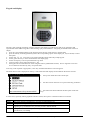
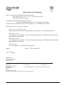
Declaration of Conformity
Biochrom Ltd
Certificate No.
890333
This is to certify that the Biotrak II Microplate Reader
Part number 80-2115-80 / -81 / -82 / -83 [96-well version]
Serial number 88000 onwards
manufactured for Biochrom Ltd by its subsidiary
Asys Hitech GmbH, Nordstrasse 4, A-5301 Eugendorf, Austria
conforms to the requirements of the following Directives - 73/23/EEC & 89/336/EEC
Standards to which conformity is declared
EN 61 010-1: 1993 and A2: 1995
Safety requirements for electrical equipment for measurement, control and laboratory use
EN 50 081-1: 1992
Electromagnetic compatibility – Generic emission standard part 1. Residential, commercial and
light industrial environments
EN 50 082-1: 1997
Electromagnetic compatibility – Generic immunity standard part 1. Residential, commercial and
light industrial environments
EN 1658: 1996
In Vitro Diagnostics – Requirements for marking
Signed:
Dated: 23rd November 2002
David Parr
Managing Director
Biochrom Ltd
Postal address
Telephone
Telefax
Biochrom Ltd
22 Cambridge Science Park
Milton Road
Cambridge CB4 0FJ
England
+44 1223 423723
+44 1223 420164
e mail: [email protected] website: http://www.biochrom.co.uk
Registered in England No: 974213
Registered Office: 22 Cambridge Science Park, Milton Road, Cambridge CB4 4FJ, England.
Issue 1.1, 02/2003
Biotrak II plate reader user manual, English
1
CONTENTS
Declaration of Conformity
1
UNPACKING, POSITIONING AND INSTALLATION
Power Requirements
Environmental Requirements
Essential Safety Notes
3
3
3
4
OPERATION
Introduction
Keypad and display
Method Definition
Method Definition: Filters
Method Definition: Layout (for controls and standards)
Method Definition: Samples
Method Definition: Calculations
Method Definition: Factors
Method Definition: Transformation
Method Definition: Thresholds
Method Definition: Validation
Method Definition: Calibration
Method Definition: Printout
Saving Method Definition
Running a method
Recalling a plate
Uploading and downloading plate data results and assay protocols
Method download, upload, saving and sorting
Descriptions of keys:
Method download and storage.
Adding methods
Plate upload and download
Storing plates on a file
Messages
Set up
Printer
Filters
Date / Time
Contrast
Language
5
5
6
7
7
7
8
8
8
8
9
9
9
9
9
10
10
10
10
11
11
11
12
12
13
13
13
13
13
13
13
ACCESSORIES
14
MAINTENANCE
After Sales Support
Fuse Replacement
Filter Replacement
Cleaning an interference filter
External cleaning
Instrument disinfection
15
15
15
16
16
16
17
SPECIFICATION AND WARRANTY
18
2
Biotrak II plate reader user manual, English
Issue 1.1, 02/2003
Unpacking, Positioning and Installation
1.
Visually inspect the container for damage, before opening it.
Report any damage immediately to the forwarding agent or to the delivery carrier.
2.
Place the carton in an upright position and open it.
3.
Remove the upper cardboard box carefully.
4.
Lift the instrument out of the carton and place it on a flat surface, free from dust, vibration and away from direct
sunlight.
5.
Visually inspect the instrument for loose, bent or broken parts.
Report any damage immediately.
6.
Compare the instrument's serial number, attached on the rear panel of the instrument, against the serial number of
the instrument on the delivery (shipping) note and packing list.
7.
Check the instrument accessories against the delivery (shipping) note and packing list.
8.
Please save all packing materials, as they may be required for later transportation.
Power Requirements
The instrument has a universal power supply that requires no setting for the local voltage. The voltage must be in the range
from 85 to 264 V AC, 48 to 400 Hz.
WARNING: For safe operation of the equipment it is mandatory that it is connected to a wall
socket equipped with a ground (earth) connector.
Ensure, that the voltage supplied to the instrument is correct to this specification and the correct rating and type of fuses
fitted.
Fuse Ratings:
T 3.5 A
For instructions how to change fuses please refer to chapter 8 of this manual.
Environmental Requirements
The instrument should be placed on an even surface that is free from dust, solvents and corrosive vapours (50 cm x 35 cm length x width).
Vibration and direct sunlight should be avoided.
Operating Temperature
+10 to + 35° C
Operating Humidity
0 to 80 % ( Non condensing)
Environmental conditions
Humidity 5 to 95%, non condensing (storage only
Maximum altitude 2000m
Before the instrument is installed and switched on, it should be left to stand for at least 2
hours, so there is no possibility of condensation causing a damage or malfunction.
Please Note:
•
Only use the power cable supplied with the instrument or a power cable with protective earth connection carrying the
CE-mark.
•
The power outlet the instrument is connected to has to meet the applicable technical safety requirements!
•
When the instrument is switched on, part of the instrument initialization process involves the microplate tray coming
out and going back in again.
Issue 1.1, 02/2003
Biotrak II plate reader user manual, English
3
Essential Safety Notes
•
If inflammable, toxic or biologically hazardous substances are used when operating the equipment, please observe the
instructions and precautions enclosed with such substance.
•
Never spill fluids in or on the equipment.
•
Wash your hands thoroughly after handling test fluids.
•
If equipment has been in contact with hazardous substances, it must be disinfected prior to shipment in accordance
with the effective provisions.
•
Do not touch the plate during movement of the plate transport (risk of injury).
•
This instrument should be serviced by an authorized service person only since it contains live parts.
There are a number of warning labels and symbols on your instrument. These are there to inform you where potential
danger exists or particular caution is required. Before commencing installation, please take time to familiarise yourself
with these symbols and their meaning.
Caution (refer to accompanying documents).
Background colour is yellow, symbol and outline are black.
4
Biotrak II plate reader user manual, English
Issue 1.1, 02/2003
OPERATION
Introduction
Your visible microplate reader is intended for in Vitro Diagnostic use. The software supplied with the reader sets a new
benchmark for flexibility, powerful evaluation options and ease of use. Your instrument:
•
•
•
•
•
•
•
•
can save up to 120 methods
• note that this includes approx. 80 pre-programmed Biotrak assay protocols which can be deleted, if required to
free up additional method storage capability for other assay protocols
• go to www.amershambiosciences.com for information on the range of cell biology assays available
measures a wide range of colorimetric end-point assays
performs kinetic measurements
evaluates the results with on-board software
outputs results to a range of printers
uploads new assay protocols from PC, if required
can download results directly to spreadsheet via the serial interface for manipulation in Excel and for data storage and
archiving
can save up to 100 sets of plate results; these can be downloaded to PC for archiving if required.
To get the full benefit of the instrument, results have to be downloaded either to printer or to spreadsheet; the instrument is
delivered with a serial and parallel cable for connection to PC and printer, respectively.
The optical system consists of a visible lamp, condenser lens, interference filters on a six position filter wheel, an optical
fibre bundle to take light to a focusing lens for each of the eight measurement channels and eight silicon photo-detectors
with another lens in front of each of these.
The instrument features digital light control. The lamp intensity is monitored and controlled so that measurement errors
caused by undetected light control problems are prevented. Thus every time a filter and wavelength is changed, a
calibration run is initiated and the lamp intensity for each wavelength is adjusted to a value that guarantees optimum
measurement conditions and the highest resolution. When the first of the calibration runs is done, the light intensity for
each wavelength is recorded by the system so that for any subsequent measurements the light intensity can be set to the
stored value and a check is only necessary. This output for each channel is known as the 100% value (or zero
measurement), and several readings are taken in the centre of each well. When samples are measured, absorbance is
calculated relative to the 100% values. The resulting signal is then filtered and displayed. The advantages of digital light
control are:
•
•
•
Prevention of drift out of the optimum operating range, a problem with analogue light control systems
Detection of lamp failure
Active filter detection; if the light value is different to the value stored in memory due to a wrongly inserted or
defective filter, an error message will be displayed.
In addition to the four filters supplied as standard, a wide range of other filters is available to enhance the capability of the
product.
User knowledge of ELISA techniques and microplate handling is assumed.
Issue 1.1, 02/2003
Biotrak II plate reader user manual, English
5
Keypad and display
The 240 x 128 pixel high resolution, graphical, liquid crystal display provides the user with set up parameters and
experimental results and the keypad is a hard wearing, spill-proof membrane. Navigating around the menu structure is
simple:
1. press the corresponding number on the keypad to enter the user mode choices or numeric data
2. press the soft key on the keypad directly below the corresponding option on the display (F1, F2, F3 and F4) to select
that option
3. use the four 3456 cursor keys to navigate around the options when the prompts appear
4. use the green enter key to move forward to the next display page
5. use the red stop key as an escape mechanism to go back
6. incorrect entries can be removed using the ← key
7. the keypad can be locked when not in use using the lock key (default PIN is 9999). Service engineers can access
service functions from here by entry of a specific PIN
Text entry, when required or appropriate, is also easy and described when its use first appears.
The main menu screen is displayed on start up. This and all the other displays are divided into three main sections:
•
the top line which shows the current topic
•
the main section which serves to present the entry parameters
• the bottom line which indicates the description of the softkeys.
In some cases, especially when a graphical content is shown, the top and / or the bottom line are not shown.
Run
Select
Recall
Define
Set up
6
This option starts a measurement with the last used or defined method.
This option selects a pre-defined or previously stored method to use
This option recalls previously stored measurement data.
This option enables a new method to be defined (Method Definition), either from the
beginning or by modification of a previously stored or default method
This option enables the basic plate reader parameters, such as printer driver and filter set
up/calibration, to be set up.
Biotrak II plate reader user manual, English
Issue 1.1, 02/2003
Method Definition
Method Definition: Filters
•
•
•
•
Measurement
Use the 34 keys to select the filter to be used for measurement.
Reference
Use the 34 keys to select the filter to be used as a reference; use “none” for no filter. The reference value, usually
620nm, is subtracted from the measured value to correct for imperfections etc. on the plastic microplate; these can
have a great effect on low OD measurements.
Shake
Press F2 if plate shaking is required before measurement; this is often used if working with cells so they do not settle
on bottom of well. Enter the shaking time required in seconds and the degree of shaking. The options are slow /
medium / fast / extreme shake and a combination of speed and travel distance; trail and error will identify the most
relevant option for your application. Press F4 to accept the entries.
Kinetics
Press F4 if kinetics is required. The assay time is defined from the assay measurement interval and the number of
measurements required; note that a measurement is taken at time zero. Press F4 to accept the entries.
Press enter to move to the next method definition box.
Method Definition: Layout (for controls and standards)
•
•
•
•
•
Press F3 to define default directions (horizontal or vertical) for replicates and samples; horizontal and vertical,
respectively, are recommended. Press F4 to accept the entries.
Press F1 to select the well type required from the options listed at the bottom of the display box. Note that the terms
are just names and whatever you want them to be, they are not “tied”. For example, LP and HP can be used to
substitute for terms T1 and T2 defined in a specific test kit; LP and HP do not have to be used in threshold
determinations. This is so that terms used previously by the user are not forgotten.
Suggested descriptions and typical uses, where appropriate, are given below:
Blk
Blank
NC
PC
LP
HP
CO
QC
ST
Negative Control
Positive Control
Low Positive
High Positive
Control
Quality Control
Standards
The absorbance of the blank value(s) are automatically subtracted from the
absorbance of the other wells.
Use for qualitative / screening tests
Use for qualitative / screening tests
Use to see if results are outside pre-defined thresholds
Use to see if results are outside pre-defined thresholds
Use as required
Use as required
Use for quantitative determinations; a maximum of 16 standards can be used
Press F4 to place the required well type in the plate layout that is shown on the display. Enter replicates by repeat
pressing of F4 as appropriate. By alternating between F1 and F4 it is possible to build up the plate as required. You
can come back to edit the layout if required. Use 3456 to move around the plate layout if necessary; as you do
this you can see what has been assigned to each well
When ST is selected using F1, ST.01 option appears as F2. After placing these on the layout, press F2 to get ST.02. A
total of 16 standards, with replicates, can be built up in this way.
• When doing standards, note that the concentrations are entered later on.
Press enter to move to the next method definition box.
Issue 1.1, 02/2003
Biotrak II plate reader user manual, English
7
Method Definition: Samples
•
•
•
Use 3456 to move around the plate layout if necessary
Place the first sample (and replicates) using F4, the press F1 to get Smp.02. Use F4 to place the second sample, and
repeat as necessary
Press F2 to fill define all remaining wells as samples (no replicates)
To erase all already defined sample positions press the Backspace ( Í) for a few seconds.
Press enter to move to the next method definition box
Method Definition: Calculations
Use the 34 to select if an option is required, and 56 to move onto the next.
Selected options are displayed in sequence when this method definition box is left.
•
•
•
•
Factors
Transformation
Thresholds
Validation
Factors and Validations are not used for Biotrak assays.
Press enter to move to the next method definition screen. Depending on the selected options different screens will be
shown.
Method Definition: Factors
Use this option to enter a constant specific to a particular test, for example to compensate for batch variations if biological
materials are being used as part of the assay kit. Thus if the material is less biologically active than it should be, the
manufacturer will specify the use of a factor or factors to normalise results to what they should be.
Note that factors entered here are not used as factors, per se, in user-defined equations, but that the normalised results are
used in such equations.
Press enter to move to the next method definition screen
Method Definition: Transformation
Use this option to define a calculation equation to be applied to each well. The equation should be written down first, and
is then entered in stages; all typical mathematical functions are available ( + /- , sqr, abs, log, log10, x², etc.) and Pow
means (power of x).
There are three groups of elements that can be selected by pressing the F1 (Alt) key. The first group contains controls
(single and average), the second one operators like +, -, /, etc. and the third one all available mathematical and logical
functions.
Use F2 and F3 to select the desired element and F4 to place it
Press enter to move to the next method definition screen.
8
Biotrak II plate reader user manual, English
Issue 1.1, 02/2003
Method Definition: Thresholds
Use this option to define the threshold limits to determine whether a sample is negative, positive or in the “grey” zone
where they should be re-tested. Limits can be defined for the measured abs value (OD), transformed equation or
concentration values depending on the test protocol. This option enables results for screening tests to be grouped.
The example below shows show thresholds should be entered; a negative result is any OD that is 0.8 or more above that of
the positive control whereas a positive result is 0.6 or below that of the positive control. Anything in between these is in
the grey zone and should be re-tested.
Press enter to move to the next method definition box
Method Definition: Validation
Use this option to apply parameters to ensure that the test is valid within the requirements stated by the assay test protocol.
If the parameters go outside of the verification limits defined by the test, the results are considered not valid.
Press enter to move to the next method definition box
Method Definition: Calibration
Use this option to enter the values of the standards, if they have been selected in the plate layout. (you can go back and edit
the plate, if required, using the stop key). Use 56 to move onto the next.
Use F1 as a quick way of entering a serial dilution series.
Units can be defined using the alphanumeric routine.
Select the analysis model for the standard curve using 34; Linear regression, Parabolic, Cubic, Point to Point (linear
interpolation), Spline, 4-parameter.
Select the y- and x-axis format required for presentation of the results; linear/linear, log/linear, linear/log, log/log.
Press enter to move to the next method definition box
Method Definition: Printout
Use this option to define what is to be printed for the results. Use 3456 to select if the plate layout is required, whether
the absorbance / transformed / concentration values are required, whether the thresholds are required (if used) and whether
the graphic of the standard curve is required together with statistical calculations.
Press enter to move to the next method definition box
Saving Method Definition
The complete method has now been defined.
It can be saved over the top of an existing method (F3) or, more usually, as a new method. Use 56 to locate an empty
method slot and F4 to append. Then enter the method name using the alphanumeric function and press enter. This new
method is then placed as 1 in the start up box that now appears.
Issue 1.1, 02/2003
Biotrak II plate reader user manual, English
9
Running a method
This can either be done immediately after defining a method (press 1) or by recalling an existing method (press 2, select
using 56 and F4).
Each plate that is run for each method has to have an unique ID. This should be entered; all data is stored in the instrument
memory (1 Mb), and can be recalled for analysis at a later date using this ID and the Recall Plate option on the main menu.
To start the measurement press either key 1 (RUN) or 2 (Select a method). The plate carrier will move out now, allowing
to load the prepared microplate.
The F3 key allows to select that either the results is printed automatically after the measurement (F3 = Auto) or that the
data are stored in the memory only for later printing (F3 = Rec). This can speed up the measurement of a batch of plates
significantly.
When less than the maximum number of samples should be processed the number of existing samples can be entered. This
will avoid that empty well positions show unwanted results.
When the plate ID has been entered press the RUN or the ENTER key to start the measurement. During reading the screen
shows a status message. A soft-key labelled ‘STOP’ is the only key active during reading and subsequent printing. Up to
100 plate data results can be stored in memory; after this is full, the new results overwrite the first results. To avoid this,
results can be downloaded to PC for archiving.
Recalling a plate
Previously run assays are stored using the unique plate ID, and can be recalled from the home page by pressing key 3 and
the ID
Uploading and downloading plate data results and assay protocols
The ability to download plate data results means that such results can be permanently archived in addition to having a print
out or download to spreadsheet. New assay protocols can be uploaded into the instrument easily, meaning that they can be
prepared away from the laboratory. Note also that when the instrument’s storage capacity of 120 methods and 100 plate
results is full, these can be downloaded for archiving and removed from the instrument to make space for new ones.
The procedures for doing this are easily achieved using the instrument simulation software on the CD supplied with the
instrument, since late data and methods are stored in different files on this.
Method download, upload, saving and sorting
Connect the reader and the computer with the serial cable supplied.
Locate the folder Reader > Upload / Download on the CD and double click on the file vrsim.exe to load the simulation
software:
Select the correct COM port (serial port) in the File menu ‘Serial communication’
Then select ‘Arrange methods’.
A new window like the one below will appear.
10
Biotrak II plate reader user manual, English
Issue 1.1, 02/2003
Descriptions of keys:
Clicking on this button will download the methods stored in the reader.
Load methods stored on the computer
Load methods that are active in the simulation
Uploads the methods shown in the right pane to the reader
Stores the methods shown in the right pane into a file
Methods shown in the right pane will be active in the simulation.
Method download and storage.
Click on the button ‘Download from Instrument’. A pop-up window will appear which shows the download progress.
After the download is finished the methods are shown in the left pane. When you want to store all these methods click on
the ‘Select all’ button, then click on the
button to copy the methods into the right pane. Afterwards click on the
‘Write to File’ button to save the methods into a desired file.
In case one or more methods should not be saved they can be selected by a mouse click and deleted.
Adding methods
In order to add methods into the reader memory the existing methods must be downloaded and copied into the right pane
first. Then the methods in the left pane should be deleted (‘select all’ and ‘Delete’). Now the new methods can be loaded
either from a file are from the simulation. The desired files are copied now into the left pane. As last step click on the
‘Upload to Instrument’ button to start the upload process.
Note: Uploading methods will override all methods currently stored in the reader memory.
Issue 1.1, 02/2003
Biotrak II plate reader user manual, English
11
Plate upload and download
For plate up- and download choose ‘ Arrange plates’ from the file menu.
The plate window is showing the following information (from left to the right)
•
•
•
•
•
Sequential number of plates, the newest plate has the number 001
Code for the data source. S = simulation, R = reader, Fx = file.
Plate ID
Data and time of data generation
Method name
Storing plates on a file
Connect the reader and computer with the serial cable supplied. Press the download key, the measured data are transferred
from the reader to the PC. Select those data who should be saved and click on the ‘Write file’ key. The screen prompts for a
file name, after entering the desired filename click on the ‘save’ key.
12
Biotrak II plate reader user manual, English
Issue 1.1, 02/2003
Messages
Most messages are self-explanatory and relate to use of the instrument.
Set up
Printer
Use this option to define which printer is connected to the plate reader; literally dozens of printer drivers are available on
the instrument. Press 1 to reveal the generic types and use 56 with to select between Compatible, Epson, HP, Other. Use
56 to highlight the printer required and press enter so that the options of paper size (A4 or letter using F1), colour or
black/white (F2), serial or parallel output (F3) can be selected. Press F4 to complete printer selection.
NOTE: If using a Canon printer, use the Epson FX printer drivers.
Download to Spreadsheet
Results can be downloaded directly to Excel when the PC has the Spreadsheet Interface Software installed and the
two are linked with the serial cable supplied with the instrument; detailed instructions are supplied with the
software. Using the spreadsheet, results can be formatted or manipulated as appropriate prior to inclusion in
reports or archiving / saving to hard disk.
Filters
Filters can be easily changed or removed for cleaning; see Maintenance. When this is done they must be calibrated using
this option by pressing the F3 or F4 key.
Date / Time
Use this option to change the date and time with 56 and the keypad. A choice of am, pm or 24 hour clock is available.
Contrast
Use this option to change the contrast of the liquid crystal display using the F1 and F2 keys.
Language
Use 56 to select the language that is used on the displays and print outs.
Issue 1.1, 02/2003
Biotrak II plate reader user manual, English
13
ACCESSORIES
14
Part Number
Description
80-2112-79
enquire
Hewlett Packard DeskJet printer
Biotrak II washer
80-2115-90
80-2115-91
80-2115-92
80-2115-93
80-2115-94
80-2115-95
80-2115-96
80-2115-97
80-2115-98
405 nm filter
450 nm filter
492 nm filter
562 nm filter
590 nm filter
595 nm filter
620 nm filter
665 nm filter
750 nm filter
Biotrak II plate reader user manual, English
Issue 1.1, 02/2003
MAINTENANCE
After Sales Support
We supply support agreements that help you to fulfil the demands of regulatory guidelines concerning GLP/GMT.
•
•
•
Calibration, certification using filters traceable to international standards
Certificated engineers and calibrated test equipment
Approved to ISO 9001 standard
Choice of agreement apart from break down coverage can include
•
•
Preventative maintenance
Certification
Observe all necessary precautions if dealing with hazardous samples or solvents
User maintenance is restricted to changing the filters and mains fuses. For any other maintenance operation or rectification
contact your local supplier.
Fuse Replacement
The following steps must be performed to replace the fuse, which is located above the power cable connection, in the rear
panel of the instrument.
WARNING
Before replacing fuses, disconnect the power cord. To avoid risk of fire, replace fuses only with same type and rating
1.
2.
4.
5.
6.
Switch off the instrument and unplug the power cord.
Open the plastic cover of the fuse compartment, by inserting a screw driver into the slot at the left side of the
cover and pushing the cover out.
3.
Pull the fuse holder away from the instrument.
Replace the fuses only with the same type and rating.
Ensure that the fuses have the correct rating; T 3.5 Amp (slow blow type)
Replace the fuse holder.
Reconnect the power cord and switch the instrument on
WARNING: If the fuse continues to blow, please call for service.
Issue 1.1, 02/2003
Biotrak II plate reader user manual, English
15
Filter Replacement
The instrument is supplied with a filter wheel that contains up to 6 changeable filters.
To replace one or more of these filters, please perform the following procedure:
1.
2.
3.
4.
5.
Switch off the instrument.
Remove the holding screw of the filter compartment cover which you can find at the right side of the instrument.
Remove the filter compartment cover.
Rotate the filter wheel, until the required filter or filter position is at the front. The filter position one is marked
with a yellow sticker. Filter position two is located above the filter one.
Pull the filter that is to be changed out of the filter wheel.
Carefully insert the 'new' filter in to the filter wheel
6.
C A U T I O N:
Carefully hold the filter only by the edges to avoid any finger prints on filters.
6.
7.
8.
Close the filter compartment cover.
Switch the instrument on.
After changing a filter a calibration run, where the lamp intensity is for each wavelength is adjusted to a value
that guarantees optimum measurement conditions and the highest resolution, is performed.
Cleaning an interference filter
If an interference filter is dirty it needs to cleaned. For the cleaning procedure you need low-lint cotton-tipped swabs and a
lens cleaning solution or reagent-grade isopropyl alcohol.
First blow off dust and dirt with pressurised gas. Apply a few drops of the cleaner on both sides of the filter and wipe-off
the dirt with the cotton swabs. Allow the cleaner to evaporate and then visually check the filter surface for streaks or spots.
If there are any repeat the procedure.
When streaks or spots are visible which cannot be removed by the procedure as described above most probably they are
inside the filter. In such a case the filter must be replaced.
Note:
Interference filters do have a limited lifetime of a few years, depending on the humidity and ambient temperature. Under
tropical conditions a filter may get unusable within less than two years.
External cleaning
This instrument is a precision instrument and requires regular cleaning to ensure the continued precision.
Liquid Spills
If any liquid is spilled in the instrument, it should be IMMEDIATELY removed so that the liquid does not run in to the
Optical System and causes a loss of accuracy.
Regular cleaning
The housing of the instrument should be cleaned regularly with a mild household cleaning agent.
Warning: Do not use aggressive solutions
16
Biotrak II plate reader user manual, English
Issue 1.1, 02/2003
Instrument disinfection
All parts of the instrument that come into contact with patient sera or positive controls must be treated as potentially
infectious.
It is therefore very important that the instrument is thoroughly disinfected before it is removed from the laboratory or any
servicing is performed on it.
Disinfection Procedure
If the laboratory has no specific disinfection procedure, the following procedure should be used to disinfect the instrument.
The instrument should be disinfected using a suitable disinfection solution.
1.
2.
3.
4.
5.
6.
7.
8.
9.
Disconnect the instrument from the mains power supply.
Disconnect the instrument from the computer.
Carefully wipe all the outside surfaces of the instrument and the plate support area with a wad of cotton wool
that has been soaked in the disinfection solution.
Ensure that disposable gloves are worn.
Place the instrument in to a large plastic bag.
Place a wad of cotton wool that has been soaked in the disinfection solution in to the plastic bag.
Ensure that the wad is not touching the instrument.
Close and seal the plastic bag.
Leave the instrument to stand in the plastic bag for at least 24 hours.
After the standing time, remove the instrument from the plastic bag and wipe all the outside surfaces of the
instrument and the plate support area with a wad of cotton wool which has been soaked in a 50% Alcohol
solution.
Repeat the disinfection procedure on any accessories which are also being moved or returned.
Issue 1.1, 02/2003
Biotrak II plate reader user manual, English
17
SPECIFICATION AND WARRANTY
Wavelength range:
Filters:
Photometric method:
Light source:
Photodetector:
Resolution:
Measurement range:
Accuracy:
Repeatability:
Reading speed:
Digital output:
Dimensions and weight:
Power requirements:
400 - 800 nm.
Dielectric interference filters. Filter wheel for up to six
filters. 405, 450, 492 and 620 nm supplied as standard
Multi channel, optical system with self calibration and
digital light control
Tungsten Halogen, expected life time 10 million readings
Multiple silicon photodiodes
0.001 OD.
0.000 – 4.000 OD
+/- 1.0% (0 – 2.0 OD)
+/- 0.5% (0 – 2.5 OD)
Single wavelength: 5 secs
RS 232 bi-directional and Centronics parallel
44 x 29 x 23 cm (W x D x H), 10 kg
90 – 250 V, 47 – 63 Hz (autosensing), 80VA
Specifications are measured at a constant ambient temperature and are typical of a production unit. As part of our policy of
continuous development, we reserve the right to alter specifications without notice.
Warranty
Your supplier guarantees that the product supplied has been thoroughly tested to ensure that it meets its published
specification. The warranty included in the conditions of supply is valid for 12 months only if the product has been used
according to the instructions supplied. They can accept no liability for loss or damage, however caused, arising from the
faulty or incorrect use of this product.
18
Biotrak II plate reader user manual, English
Issue 1.1, 02/2003