1
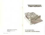
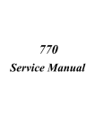
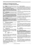
EasyMelt-0.5/1/2
UPT-016-500/510/520-00
Desktop Melter
Model: Easy Melt - 0.5/1/2 kg
Part Number: UPT-016-500/510/520-00
User Manual
Version 1.2
www.ultraflexpower.com
1
EasyMelt-0.5/1/2
UPT-016-500/510/520-00
TABLE OF CONTENTS:
SECTION A:
GETTING STARTED GUIDE ............................................................................. 4
A1:
SAFETY INSTRUCTIONS .......................................................................................... 4
A1.1
IMPORTANT NOTES ........................................................................................... 4
A1.2
SAFETY PRECAUTIONS ....................................................................................... 5
A1.2.1
ELECTRICAL SHOCK HAZARDS ....................................................................... 5
A1.2.2
GROUNDING ................................................................................................. 5
A1.2.3
SAFETY AND PRECAUTION SYMBOLS USED IN THIS MANUAL ....................... 6
A2:
INSTALLATION AND STARTUP ................................................................................ 7
A2.1
INSTALLATION PROCEDURE ............................................................................... 7
A2.2
UNPACKING AND INSPECTION ........................................................................... 7
A2.3
SELECTING THE DEVICE SITE ............................................................................... 8
A2.4
COOLING REQUIREMENTS ................................................................................. 8
A2.5
AC INPUT CONNECTION ..................................................................................... 8
A2.6
START-UP........................................................................................................... 9
A2.7 USING THE MACHINE ............................................................................................. 9
A3:
MAINTENANCE ..................................................................................................... 10
A3.1
SCHEDULING .................................................................................................... 10
A3.2
PERSONNEL ..................................................................................................... 10
A3.3
INSPECTION AND MAINTENANCE PROCEDURE ................................................ 10
A4:
SERVICE ................................................................................................................ 11
A4.1
GENERAL.......................................................................................................... 11
A4.2
SERVICE CONTACT INFORMATION ................................................................... 11
SECTION B:
PRODUCT SPECIFICATIONS AND FEATURES ................................................ 12
B1:
POWER SUPPLY SPECIFICATIONS .......................................................................... 12
B1.1
OVERVIEW ....................................................................................................... 12
B1.2
DEVICE SPECIFICATIONS TABLE ........................................................................ 13
B1.3
CONNECTION DIAGRAM .................................................................................. 14
B1.4
DEVICE SPARE PARTS DIAGRAM ...................................................................... 15
B1.5
DEVICE ELECTRONOCS SPARE PARTS DIAGRAM..........................................16
B2:
HEAT STATION SPECIFICATIONS............................................................................ 17
B2.1
PRODUCT OVERVIEW ...................................................................................... 17
B2.2
HEAT STATION SPECIFICATIONS ....................................................................... 17
B3:
CONTROLS AND OPERATION ................................................................................ 17
B3.1
CONTROL PANEL OVERVIEW............................................................................ 17
B3.2
CONTROLS AND INDICATORS........................................................................... 18
B3.3
REGULATION MODES AND SYSTEM STATUSES ................................................ 19
B3.4
MENUS AND NAVIGATION............................................................................... 20
B3.4.1
Main Menu Navigation............................................................................... 20
B3.4.2
Heat ON Menu Navigation ......................................................................... 21
B3.4.3
SYSTEM MENU Navigation ......................................................................... 22
B3.4.4
EXTENDED MENU Navigation ..................................................................... 24
B3.5
CONTROL MODES ............................................................................................ 26
SECTION C:
TUNING AND TROUBLESHOOTING .............................................................. 26
Version 1.2
www.ultraflexpower.com
2
EasyMelt-0.5/1/2
UPT-016-500/510/520-00
C1:
C2:
C3:
LOAD TUNING GUIDE............................................................................................ 26
ALARMS, FAULTS AND WARNINGS ....................................................................... 26
ACCESSORIES ........................................................................................................ 28
Version 1.2
www.ultraflexpower.com
3
EasyMelt-0.5/1/2
UPT-016-500/510/520-00
SECTION A: GETTING STARTED GUIDE
A1: SAFETY INSTRUCTIONS
A1.1. IMPORTANT NOTES
1. This manual is valid only for the Model and the associated Revision number(s) specified in the cover sheet of this
manual. A Change Page may be included at the end of the manual. All applicable changes are documented with
reference to the equipment Revision and Serial number. Before using this Instruction Manual, check your equipment
nameplate to identify your Model and Revision number. If in doubt, contact your nearest Ultraflex Power
Technologies (UPT Corp.) Representative;
2. This document contains information proprietary to UPT Corporation. All rights are reserved. No part of this
document may be reproduced, transmitted, processed or recorded by any means or form, electronic, mechanical,
photographic or otherwise, nor be released to any third party without the express written consent of UPT
Corporation;
3. In this document period “.” will be used as a decimal point delimiter.
4. Data subject to change without notice;
5. All Information contained in this manual is the latest information available at the time of printing. The right is
reserved to make changes at anytime without notice. UPT Corp. makes no warranty of any kind with regard to this
material and assumes no responsibility for any errors that may occur in this manual;
6. Safety First!
YOU AND NOT THIS MANUAL ARE RESPONSIBLE FOR ALL SAFETY PRECAUTIONS.
This manual is for reference purposes only. Personnel should be trained on proper operation of this equipment
before using. Only authorized personnel may perform any troubleshooting or repair on any UPT manufactured
equipment. Failure to comply will void warranty.
Please, contact the UPT Service Department before servicing any UPT equipment.
Lethal voltages may be present in equipment surrounding and/or connected to this equipment. Read the following
warnings carefully and study this entire manual before operating the system. Failure to observe warnings may result
in equipment damage, serious personal injury, or death.
If the equipment is used in a manner not specified by this manual, the protection provided by the equipment may be
compromised and damage to the unit may occur.
1. Only qualified persons who have been trained in the operation of this equipment and are familiar with the
technology should be permitted to operate the system;
2. Installation, assembly, inspection maintenance and servicing are to be performed by authorized personnel only;
3. Always have the Power Supply completely powered OFF and locked out before performing any service, inspection
or maintenance;
4. Even with the Power Supply OFF, live voltages still exist within the cabinet. Always power OFF and lock out the
external power source to ensure no one can accidentally energize it;
Version 1.2
www.ultraflexpower.com
4
EasyMelt-0.5/1/2
UPT-016-500/510/520-00
5. Ensure that all external wiring conforms to applicable codes;
6. Obey all warnings and use good common sense;
A1.2. SAFETY PRECAUTIONS
A1.2.1. ELECTRICAL SHOCK HAZARDS
This manual is written for personnel familiar with the technology pertaining to the operation of induction heating
equipment. Such personnel should be thoroughly familiar with the hazards associated with this equipment and
electrical equipment in general, and they should have received proper safety procedure training.
Hazardous voltages are present within this product during normal operation. The product should never be operated
with the cover removed unless equivalent protection of the operator from accidental contact with hazardous
internal voltages is provided. Operators must be trained in its use and exercise caution as well as common sense
during use to prevent accidental shock.
There are no operator serviceable parts or adjustments within the product enclosure. Refer all
servicing to trained service technician.
Source power must be removed from the product prior to performing any servicing.
This product is designed for use with nominal a-c mains voltages indicated on the rating
nameplate.
A1.2.2. GROUNDING
This product is a Class 1 device which utilizes protective grounding to earth to ensure operator‘s safety.
PROTECTIVE EARTHING CONDUCTOR TERMINAL -This symbol indicates the point on the product to
which the protective grounding conductor must be attached.
EARTH (GROUND) TERMINAL -This symbol is used to indicate a point which is connected to the
PROTECTIVE EARTHING TERMINAL. The component installer/assembler must ensure that this point is
connected to the PROTECTIVE EARTHING TERMINAL.
CHASSIS TERMINAL -This symbol indicates frame (chassis) connection, which is supplied as a point of
convenience for performance purposes. This is not to be confused with the protective grounding
point, and may not be used in place of it.
Version 1.2
www.ultraflexpower.com
5
EasyMelt-0.5/1/2
UPT-016-500/510/520-00
A1.2.3. SAFETY AND PRECAUTION SYMBOLS USED IN THIS MANUAL
A WARNING symbol alerts you to a hazard that may result in equipment damage, personal injury, or
death. Carefully read the instructions provided WARNING and follow all safety precautions.
A CAUTION symbol alerts you that the system may not operate as expected if instructions are not
followed.
Version 1.2
www.ultraflexpower.com
6
EasyMelt-0.5/1/2
UPT-016-500/510/520-00
A2: INSTALLATION AND START UP
A2.1. INSTALLATION PROCEDURE
The installation procedure consists of the following steps:
Unpacking the equipment;
Selecting the site where the equipment will be used;
Connecting the Heat Station (if remote Heat Station is provided);
Connecting accessories or interfacing the system with other controls (if necessary);
Completing the Power and Ground/Earth connections;
Power and ground/earth connections must be made last. Failure to do so will create a hazardous
condition that may result in equipment damage, personal injury, or death.
NOTE: UPT Corporation has a staff of field engineers who are available to supervise the installation of the
equipment. If installation service is required, contact our Technical Service Department for additional information.
Provisions for facility electrical power service are customer furnished. Requesting field engineering assistance before
customer furnished provisions are installed at the equipment site could delay equipment installation and cause
unnecessary expense.
A2.2. UNPACKING AND INSPECTION
This equipment has been thoroughly inspected and tested prior to packing and is ready for operation. After careful
unpacking, visually inspect for shipping damage BEFORE attempting to operate. If any indication of damage is found,
file an immediate claim with the responsible transport service and advise your sales representative.
Inspect equipment before installing. Damaged equipment may result in improper operation and
create a hazardous condition resulting in personal injury or death.
Inspect equipment before installing. Damaged equipment may result in improper operation and
create a hazardous condition resulting in personal injury or death.
Version 1.2
www.ultraflexpower.com
7
EasyMelt-0.5/1/2
UPT-016-500/510/520-00
A2.3. SELECTING THE DEVICE SITE
Consider the following when choosing a location for the device:
Make sure the system is installed in a debris free zone;
The device has to be connected to a power source and cooling water;
The device have to be connected to cooling system with sufficient water flow;
Make sure the device is easily accessible by the operator;
Device has to be seated on a mechanically secure surface;
A2.4. COOLING REQUIREMENTS
The power transistors and rectifiers into the device are maintained within their safe operating temperature range by
means of water cooling. The fan inlets must be kept clean from obstructions in order to insure proper air circulation.
If installed in confined spaces, care must be taken that the ambient temperature (the temperature of the space
immediately surrounding the device, does not rise above the limit specified as 40°C. Periodic cleaning of the device
exterior is recommended. The following system components are directly dependent on water cooling:
semiconductor’s heat sinks, coils, tank capacitors, output transformers. To maintain the temperature on these
components within safe limits, the following requirements apply to the inlet cooling water:
Maximum allowable temperature – 95 F (35°C);
Minimum allowable temperature - 58 F (14°C) (to avoid condensation);
Minimum water flow is required – Refer to product specifications in Section B;
Water (coolant) must be mechanically debris free;
Water (coolant) must be chemically pure (distilled water is recommended);
A2.5. AC INPUT CONNECTION
The Power supply connects to the power network through an 6 ft (1.80m), power cord (supplied). Additional fuse or
circuit breaker and residual current circuit breaker on that power branch is a good choice since it will provide extra
protection in addition to the unit’s internal protection. A mechanical switch is also recommended within the
operator‘s range and vision and possibly closer to the Power Supply.
Only trained personnel should open the unit cover and operate the breakers.
Table A1: Wiring Color Code
Color
Brown
Blue
Green/Yellow
Version 1.2
www.ultraflexpower.com
1-Phase Connection
Line 1
Neutral
Ground/Earth
3-Phase Connection
Line
Neutral
Ground/Earth
8
EasyMelt-0.5/1/2
UPT-016-500/510/520-00
NOTE: Local codes may have stringent requirements. It is the customer‘s responsibility to be familiar with and to
comply with all applicable codes concerning conductor ratings and wiring procedures. An electrician familiar with
the local regulations should determine proper wiring connections
A2.6. START-UP
1. Connect the AC and ground connections as described in Section A2.5;
2. Connect the water cooling system to the device;
3. Turn the water Cooling System ON. Make sure there is no water leaks on outside connections;
4. Turn the Power Switch on to power the system. Check for any Fault or Alarm messages. If the status screen
shows “80% Power” message, then the system is ready for operation;
See Section B of this Manual for Connections Diagrams
A2.7. USING THE MACHINE
1. Using a water hose connect the machine to the water source for the cooling. In the back of the machine you will
find the connections: water in (fig. B2.1) and water out (fig. B2.2). The connection to a water tap is enough, but the
used water will be thrown away. A connection to a water tank with a circulating pump is also possible as well as to a
chiller with controlled temperature. Remember to tight strongly the hose on the connections with a clamp;
2. Connect the machine to the electric supply 220 V – single phase;
3. Crucible. Check that your crucible is good enough to make a melting. A too much used crucible can make the
casting very slow. Check also that the bottom is not too thin, you risk that it brakes during the melting causing the
metal going out;
4. Place the crucible in the melting chamber paying attention to the thermocouple positioned on the bottom. The
purpose of the thermocouple is to read the temperature of the crucible. For this reason the crucible has a hole
underneath to let the thermocouple to touch the graphite;
5. Switch on the machine pressing the main switch (fig. B2.4) positioned on the back of the machine;
6. On the control panel you have the possibility to adjust three parameters;
7. Power efficiency. This parameter determinate how fast the melting will be done. We suggest to use 80 % power in
order to have a more homogenous melting;
8. Time. This timer will start to count the set time when the furnace will reach the set temperature. It is going from 1
to 30 minutes. At the end of the time a buzzer will ring for a half second, then the furnace will stop to heat. The
purpose of this timer is to let the metal to be completely molten and mixed after the heating. If you don’t like to use
the timer, set it in “OFF” position;
9. Temperature. Set the melting temperature, the maximum suitable value is 1.300 °C;
10. Choice of parameters. In order to choose the parameters push the “SELECT”(fig. B4.10) button. The red light (fig.
B4.6-7-8) will move to the parameter you want to modify. With the help of the arrows (fig. B4.9) you can increase or
decrease the value till when you will find the desired value by checking on the display (fig B4.5);
11. Melting. Put the metal in the crucible and push the “START” (fig. B4.2) button;
12. In case you want to stop the machine push the “STOP” button (fig. B4.1);
13. If something is wrong the machine will go in “ALARM” and the red light (fig. B4.3) will go on;
Version 1.2
www.ultraflexpower.com
9
EasyMelt-0.5/1/2
UPT-016-500/510/520-00
14. The heating will start the light (fig. B4.4) will go on and the machine will heat according to the set power. It is
possible to increase or decrease the power during the melting process by pressing the power button previously
selected by the “SELECT”(fig. B4.10) button. During the cycle on the display (fig. B4.5) you will be monitoring the
temperature;
A3:
MAINTENANCE
A3.1.
SCHEDULING
The Power Supply is designed for continuous service and minimum maintenance requirements. The frequency of any
maintenance program is a function of environment, degree of equipment use, and product experience.
A3.2. PERSONNEL
Qualified personnel must perform inspection and maintenance procedures only. Personnel must read and be
thoroughly familiar with all safety precautions discussed in this manual.
A3.3. INSPECTION AND MAINTENANCE PROCEDURE
Note: Always follow approved lock-out / tag-out procedures before performing any service, inspection or
maintenance.
The following describes inspection procedures to be performed on a daily, weekly, and monthly basis.
Daily/Weekly Inspection: It is good practice to do a quick visual inspection of the unit, wiring and connections on a
daily and/or weekly basis. Report any apparent changes in performance to responsible personnel so that potential
problems can be investigated.
Monthly Inspection:
Perform the following on a monthly basis:
1. Ensure all wiring connections are secure. Visually inspect for any wear on cabling;
2. Verify that none of the enclosure’s hardware has become loose;
3. Remove any build-up debris that may occur around the fan inlet using a cloth or a vacuum cleaner. Use of
compressed air is not recommended;
4. Check the water (coolant) for mechanical debris or impurities. The water should be kept clean;
5. Wipe the Control Panel with a damp cloth to remove any dirt, prints or smudges;
6. Wipe the enclosure down with a damp cloth or paint friendly cleaner, if desired;
7. Unbolt water filter clean it and bolt carefully again;
Version 1.2
www.ultraflexpower.com
10
EasyMelt-0.5/1/2
UPT-016-500/510/520-00
A4: SERVICE
A4.1. GENERAL
If for some reason the unit fails in the field it is advisable that the unit be serviced by the manufacturer or its
authorized service representative. Should that happen, please contact us immediately (see contact information in
Section A4.2). Please have the following information about your unit available upon calling:
1. Unit Model and Revision (located on the label on the back of the unit);
2. Unit’s Serial Number (located on the label on the back of the unit);
3. Line Voltage and frequency;
4. Detailed description of the problem encountered including – load, ambient temperature at the time of the failure;
5. Detailed description of the actions taken;
6. Approximate time in service;
If our technical staff is unable to help you over the phone, then a repair authorization number (RA#) will be issued for
you. With this number enclosed in you return package you can ship the unit back for repair or request a service
engineer to repair the unit on site.
A4.2. SERVICE CONTACT INFORMATION
For technical service questions, please call:
Europe and Asia: + 359 2 480 1900
USA and Canada: + 1 631 467 6814
You may also fax your questions or request:
Europe and Asia: + 359 2 480 1910
USA and Canada: + 1 631980 4065
Or e-mail us at: [email protected]
You can also send you request through our web site.
Note: Please, include your contact information so that you can be easily reached if necessary.
Version 1.2
www.ultraflexpower.com
11
EasyMelt-0.5/1/2
UPT-016-500/510/520-00
SECTION B: PRODUCT SPECIFICATIONS AND FEATURES
B1: POWER SUPPLY SPECIFICATIONS
B1.1. OVERVIEW
The UPT-016-500/510/520 is a general purpose induction heating system designed to work with a large variety of
custom coils. It consists of two main parts placed into the same cabinet. They are:
1. Power supply – generates RF power to supply the output circuit.
2. Heat Station – houses the output circuit and interfaces it with the load by means of an induction coil.
The unit is digitally controlled through a control panel located on front panel.
450
180
360
Figure B1 - Overall Device Dimensions
Notes:
1) A tool is required to gain access to the Power Supply. This is to prevent accidental exposure to the internal high
voltages.
2) See section C of this Manual for optional equipment and Accessories.
Version 1.2
www.ultraflexpower.com
12
EasyMelt-0.5/1/2
UPT-016-500/510/520-00
B1.2. DEVICE SPECIFICATIONS TABLE
Table B1. UPT-016 Easy Melt Specifications Table
SPECIFICATIONS
RATING/DESCRIPTION
UPT-16-500
UPT-16-510
CONDITION
UPT-16-520
INPUT
AC Voltage range
Line Frequency
Input Current maximum
(RMS)
Input Power maximum
Efficiency minimum
230 VAC (±10%)
50/60 Hz
Single Phase
10 A
12 A
15.5 A
@ 230 VAC -10%
2 kVA
88%
2.55 kVA
3.2 kVA
@ 230 VAC
@ full load
OUTPUT
Control Modes
Constant Power
Output Current maximum
Output Voltage maximum
Output Power maximum
Output Frequency range
Timer Resolution
13 A (sine wave)
250V RMS
1.5 KW
2.0 kW
30-60KHz
1min/step
2.5 kW
with voltage and current
limit
@ 100% current reference
@ 230 VAC ±10% Input
@ 230 VAC Input
@ 2.0kW
1 – 30 min.
PROTECTION
Over-current
Over-temperature heat sink
20 A (RMS)
55°C
Inverter output current
Reset by depressing STOP
MISCELLANEOUS
Temperature Ranges
Humidity range
32 F (0°C) to + 104 F (40°C)
Operating
-4 F (-20°C) to + 150 F (65°C)
Storage
0 to 95%
RH Non-condensing
Operating &
Storage
PHYSICAL
Cooling
Module Dimensions
Weight
Connections
Forced water
W x D x H in/(mm)
17.7 x 14.2 x 7.1 (450 x 360 x 180)
38 lb (18 kg)
0.5GPM (2 LPM) minimum
water flow
Overall dimensions with
feet
Net weight
B1.3. CONNECTION DIAGRAM
Version 1.2
www.ultraflexpower.com
13
EasyMelt-0.5/1/2
UPT-016-500/510/520-00
4
1
2
5
3
6
Figure B2 – Rear Panel Connections
Table B2: Rear Panel Connections Table
Description
1
2
3
4
5
6
Water outlet
Water inlet
Power line fuses
Power line switch
Power line cable
Water filter
B1.4. DEVICE SPARE PARTS DIAGRA
Version 1.2
www.ultraflexpower.com
14
EasyMelt-0.5/1/2
UPT-016-500/510/520-00
Figure B3 – Device Expanded View
Table B3: Device Spare Parts List Table
Name
1
2
3
4
5
6
7
8
9
10
11
12
13
14
15
16
Front Side Easy
Partitioning Wall Easy
Induction Coil - UPT-016-520
UPT-016-500/510
Ceramic Plate base
Refractory Ceramic Base
Feet
Thermocouple
Left Side Panel Easy
Fan 60x60x15
Rear Panel Easy
Flow switch
Water Fittings
Water Filter
Main fuse holders
Cable Gland
Main Switch
Version 1.2
www.ultraflexpower.com
Part Number
2MAS-016-500-AC
2MAS-016-500-AI
1ASM-016-501-00
1ASM-016-502-00
2DET-016-500-KN
2DET-016-500-KL
4HVM-000-017-00
3SNM-000-003-00
2MAS-016-500-AE
3FAN-012-002-00
2MAS-016-500-AG
9VLO-000-054-00
2DET-016-500-KM
9VLO-000-125-00
3FFT-000-016-00
4KVT-000-021-00
3SBT-000-018-00
15
EasyMelt-0.5/1/2
UPT-016-500/510/520-00
17
18
19
20
21
22
23
24
25
Refractory Protective Cover
Metal Protective Cover
Bracket for Tank Cap
Tank Cap
Right Side Panel Easy
Electronic plate assembly
Holder Coil
Output transformer - UPT-016-520
UPT-016-500/510
Control panel
2DET-016-500-KQ
2DET-016-500-KH
2DET-016-500-LB
3CFM-105-001-01
2MAS-016-500-AD
1ASM-016-500-00
2MAS-016-500-AM
2MAS-016-500-DC
2MAS-016-501-DC
1ASM-016-540-00
B1.5. ELECTRONIC PLATE ASSEMBLY SPARE PARTS DIAGRAM
Figure B4 – Electronic Plate Assembly Expanded View
Table B4: Device Spare Parts List Table
Name
1
2
3
4
5
6
Base electronics easy
Choke assembly
Control board
Inverter board
Water heatsink
Rectifier/inrush limiter
Version 1.2
www.ultraflexpower.com
Part Number
2MAS-016-500-AK
1ASM-722-169-00
1MOD-722-700-00
1MOD-751-220-00
2DET-016-500-KV
1MOD-751-600-00
16
EasyMelt-0.5/1/2
UPT-016-500/510/520-00
7
8
Heartsink rectifier
Line filter
2DET-016-500-KR
3FTM-000-007-01
B2: HEAT STATION SPECIFICATIONS
B2.1. PRODUCT OVERVIEW
Heat Station – It is a part of the device placed into the same cabinet with HF power supply. It houses the output
circuit and interfaces it with the load by means of an induction coil.
The Heat station consists of an output matching transformer with fixed transformer ratio. air cooled tank capacitor
assembly. output terminals for mounting the coil and induction coil.
B2.2. HEAT STATION SPECIFICATIONS
Table B4. Heat Station Specifications Table
ELECTRO-MECHANICAL SPECIFICATIONS
SPECIFICATIONS
Cooling
Max Primary Current
RMS Ipmax
Output Frequency Range
Output Volts RMS Vomax
Output Transformer
Ratio Ntr
Tank Capacitor
RATING/DESCRIPTION
UPT-016-500
UPT-016-510
CONDITION
UPT-016-520
Minimum required
flow rate
Water cooled 2 LPM (0.5GPM)
13 RMS
30-50 kHz
250
21/3
21/3
18/3
Fixed
capacitance 1.2 uF
B3: CONTROLS AND OPERATION
B3.1. CONTROL PANEL OVERVIEW
The unit is digitally controlled through a control panel located on the front panel of device. The control panel utilizes
the latest microprocessor technology. The control panels are designed to display vital parameters and alpha-numeric
messages providing intuitive and informative visual feedback. The users can also navigate through easy to use
service. diagnostics and setup menus.
Version 1.2
www.ultraflexpower.com
17
EasyMelt-0.5/1/2
UPT-016-500/510/520-00
B3.2. CONTROLS AND INDICATORS
The control panel has the following controls and indicators:
5
4
6
7
8
9
3
2
10
1
Figure B4 - UPT-016-500/510/520 Control Panel Layout and Controls
Version 1.2
www.ultraflexpower.com
18
EasyMelt-0.5/1/2
UPT-016-500/510/520-00
Table B5: Control Panel Components
Name/Function
Description
1
“Stop” Button
“Stop” Button – dual function
- Stops the heating cycle. when the device is
in “Heat on” state
- Resets any faults. when the system is in
“Alarm” state
2
“Start” Button
“Start” Button – activates the heat cycle
3
LED [Green] - when
generator is heated ON
5
4 Large 7 segment LEDs
display
LED [Green] - Illuminated when HF generator
is heated ON
4 Large 7 segment LEDs display:
- Output set point (% )
- Timer (min) or “OFF”
- Temperature (ºC)
- Inverter current (Arms)
- Inverter output voltage (Vrms)
- Inverter output power (kW)
- Output frequency (kHz)
6
LED [RED] - timer status
7
8
LED [RED] - output set
point in %
LED [RED] - output set
point in %
9
“UP” and “DOWN” arrow
buttons
10
“SELECT” button
LED [RED] - Illuminated when Indicator 4
shows timer status
LED [RED] - Illuminated when Indicator 4
shows output set point in %
LED [RED] - Illuminated when Indicator 4
shows output set point in % in ºC
“UP” and “DOWN” arrow buttons – dual
function
- changing value of parameters
- scrolling through the menus
“SELECT” button:
- scrolling through the parameters. entering
menus and confirming parameter’s value
Indicator/Control
CONTROL
CONTROL
INDICATOR
INDICATOR
INDICATOR
INDICATOR
INDICATOR
CONTROL
CONTROL
B3.3. REGULATION MODES AND SYSTEM STATUSES
Device works in power regulation mode only.
Version 1.2
www.ultraflexpower.com
19
EasyMelt-0.5/1/2
UPT-016-500/510/520-00
B3.4. MENUS AND NAVIGATION
B3.4.1. Main Menu Navigation
Main Menu
POWER ON
POWER (%)
HEAT ON
TIME (min)
ALARM
TEMP (° C)
Control Panel
SW Revision.
N
2s Delay?
Y
1
POWER (%)
HEAT ON
TIME (min)
ALARM
TEMP (° C)
Last Set
Output Power
N
ERROR?
Y
Error
Y
System
Menu
Y
HEAT ON
Menu
N
“START”
Button?
N
Change Power Set Point
“SELECT”
>2s?
Y
N
“SELECT”
? 2s?
“Up” or “Dn”
Button?
N
N
“START”
Button?
Y
POWER (%)
HEAT ON
TIME (min)
ALARM
TEMP (°C)
N
“SELECT”
? 2s?
N
ERROR ?
N
“SELECT”
>2s?
Y
Y
Y
Error
System
Menu
HEAT ON
Menu
Y
POWER (%)
HEAT ON
TIME (min)
ALARM
TEMP (°C)
Thermo Regulator
Set Point
N
“SELECT”
? 2s?
N
ERROR ?
N
“SELECT”
>2s?
N
“START”
Button?
Y
Y
Y
Error
System
Menu
HEAT ON
Menu
Figure B5 - Main Menu Structure
Version 1.2
www.ultraflexpower.com
20
EasyMelt-0.5/1/2
UPT-016-500/510/520-00
B3.4.2. Heat ON Menu Navigation
HEAT ON Menu is accessible from Main Menu. by pressing “START” button. It is shown on Figure B6.
HEAT ON
Menu
POWER (%)
HEAT ON
TIME (min)
ALARM
TEMP (°C)
ERROR ?
“STOP”
Button?
N
Y
N
Error
“SELECT”
>2s?
Y
Main
Menu
Y
Extended
Menu
Y
Change Power Set
Point
1
N
N
“SELECT”
? 2s?
“Up” or “Dn”
Button?
N
Y
POWER (%)
TIME (min)
HEAT ON
ALARM
TEMP (°C)
N
“SELECT”
? 2s?
Y
N
ERROR ?
N
“STOPT”
Button?
N
“SELECT”
>2s?
Y
Y
Y
Error
Main
Menu
Extended
Menu
Y
POWER (%)
HEAT ON
TIME (min)
ALARM
Temperature ( °C )
1
TEMP (°C)
N
“SELECT”
? 2s?
N
ERROR ?
N
“STOPT”
Button?
N
“SELECT”
>2s?
Y
Y
Y
Error
Main
Menu
Extended
Menu
1
Figure B6 – HEAT ON Menu Structure
Version 1.2
www.ultraflexpower.com
21
EasyMelt-0.5/1/2
UPT-016-500/510/520-00
B3.4.3. SYSTEM MENU Navigation
SYSTEM MENU is accessible from Main Menu. by pressing “SELECT” button for 2 seconds. It is shown on Figure B7.
System
Menu
4
Y
PO WER (%)
HEAT ON
“SELECT”
2s?
TIM E (min )
ALARM
TEMP (°C )
N
“SELECT”
2s?
Control Panel
SW Revision.
P OW ER (% )
Y
HEAT ON
TIM E (min)
ALARM
TEM P (°C)
N
N
“Down”
Button ?
Y
Y
P OWER (% )
HEAT ON
“SELECT”
2s?
TIM E (min)
ALARM
TEM P (°C)
N
“SELECT”
2s?
Control Board
SW Revision.
P O WER (%)
Y
HEAT ON
TIM E ( min)
ALARM
TEMP ( °C)
N
N
“Down”
Button ?
Y
3
PO WER (%)
HEAT ON
TI ME (min)
ALARM
TEM P (°C)
“SELECT”
2s?
N
Thermo
Regulator ON
PO WER (%)
Y
HEAT ON
TIM E (min )
ALARM
TEMP (°C )
N
N
“Down”
Button ?
“Doun”
Button ?
Y
Y
“SELECT”
2s?
N
2
TIM E (min)
ALARM
3
Y
2
Thermo
Regulator OFF
P O WER ( %)
HEAT ON
Y
TEMP ( °C)
N
Y
“Up” Button ?
Version 1.2
www.ultraflexpower.com
N
“SELECT”
2s?
22
EasyMelt-0.5/1/2
UPT-016-500/510/520-00
2
Y
POWER (%)
HEAT ON
“SELECT”
2s?
TIME (min)
ALARM
TEM P (°C)
N
“SELECT”
2s?
N
POWER (%)
Y
TIME (min)
HEAT ON
A LARM
TEMP (°C)
Water Flow
L/min
N
“Down”
Button ?
Y
POWER (%)
HEAT ON
TIM E (min)
ALARM
TEM P (°C)
“Doun”
Button ?
N
Y
4
N
“SELECT”
2s?
Y
Main
Menu
1
Figure B7 – SYSTEM Menu Structure
Version 1.2
www.ultraflexpower.com
23
EasyMelt-0.5/1/2
UPT-016-500/510/520-00
B3.4.4. EXTENDED MENU Navigation
EXTENDED MENU is accessible from Heat ON Menu. by pressing “SELECT” button. For 2seconds. It is shown on
Figure B8. This menu allows additional basic inverter parameters to be shown – power. current. voltage. frequency.
Extended
Menu
5
POWER (%)
HEAT ON
TIME (min)
ALARM
TEMP (°C)
Error
Y
ERROR ?
OUTPUT
POWER
“STOP”
Button?
N
Main
Menu
Y
N
N
1
“SELECT”
? 2s?
Y
POWER (%)
OUTPUT
CURRENT
Main
Menu
Y
HEAT ON
TIME (m in)
ALARM
TEMP ( °C)
“STOP”
Button?
N
ERROR ?
Error
Y
N
“SELECT”
? 2s?
N
Y
POWER (%)
HEAT ON
TIME (min)
ALARM
TEMP (°C)
Error
Y
ERROR ?
N
OUTPUT
VOLTAGE
“STOP”
Button?
Main
Menu
Y
N
N
1
“SELECT”
? 2s?
Y
POWER (%)
FREQUENCY
HEAT ON
TIME (m in)
ALARM
TEMP ( °C)
6
Version 1.2
www.ultraflexpower.com
24
EasyMelt-0.5/1/2
UPT-016-500/510/520-00
6
Main
Menu
Y
“STOP”
Button?
N
ERROR ?
Y
Error
Y
Main
Menu
N
“SELECT”
?2s?
Y
POWER (%)
HEAT ON
TIME (min)
ALARM
TEMP (°C)
Error
Y
ERROR ?
Power Set
Point
“STOP”
Button?
N
N
N
1
“SELECT”
?2s?
Y
POW ER (%)
TIMER
HEAT ON
TIME (min)
ALARM
TEMP (°C)
Main
Menu
Y
“STOP”
Button?
N
ERROR ?
Y
Error
N
“SELECT”
?2s?
N
Y
POWER (%)
HEAT ON
TIME (min)
ALARM
TEMPERATURE
TEMP (°C)
Error
Y
ERROR ?
N
“STOP”
Button?
Y
Main
Menu
N
1
Figure B8 – EXTENDED Menu Structure
Version 1.2
www.ultraflexpower.com
25
EasyMelt-0.5/1/2
UPT-016-500/510/520-00
B3.5. CONTROL MODES
Control Modes of Operation
There are two control modes of operation:
[Auto] – In this mode device automatically holds up previously set temperature of the crucible. In this mode thermo
regulator is switched ON ( see Fig.B7).
[Manual] – In this mode it is supposed that there is not thermocouple mounted. Thermo regulator is switched OFF
( see Fig.B7) and operator have to watch crucible temperature.
Note: When thermo regulator is switched OFF. the parameter “TEMPERATURE” is invisible on the 7 segment LED
display.
SECTION C:TUNING AND TROUBLESHOOTING
C1: LOAD TUNING GUIDE
Because of fixed tank circuit and load (graphite crucible) device is factory tuned and doesn’t need additional load
tuning.
C2: ALARMS. FAULTS AND WARNINGS
For every ERROR which appears during normal working of the device. is valid flowchart shown on Fig.C1.
Error
POWER (%)
HEAT ON
TIME (min)
ALARM
TEMP (°C)
ERROR
CONDITION
N
“STOP”
Button?
Y
Main Menu
1
Figure C1 – ERROR Menu Flowchart
Table C1. Alarms and Fault Messages
Version 1.2
www.ultraflexpower.com
26
EasyMelt-0.5/1/2
UPT-016-500/510/520-00
Flt.
Fault Description
Condition
Cause
Advice
Check resonant loop
connections - load coil. tank
capacitors. Transformer taps.
Possible inverter board Part
Number MOD-016-210 failure.
Possible FET/IGBT failure in the
Power supply. Contact our
Service department
Check resonant loop values.
tank capacitors or control
board. Check load coil for
shorted turns.
Check fans. blockages of the
vents or fan filters. Cooling
water temperature or water
filters.
Check resonant loop
connections - load coil. tank
capacitors. Transformer taps.
Possible inverter board Part
Number MOD-016-210 failure.
Er1
Tuning Fault
(Phase Fault)
Primary V & I out
of phase
Can't find resonant
frequency
Er2
Current Fault
Iprimary > I Max
Output current
exceeds the limit
Er3
Frequency Fault
F < Fmin or F >
Fmax
Frequency goes out of
the pre-programmed
range during Heat On
Er4
PS Over
Temperature
T°heat sink >60°C
The heat sink of the
power supply exceeds
the max allowed T°
Er5
Auto tune fault
Appearance only
in service mode
after sweeping
Can't find resonant
frequency, or the
frequency is out of
range.
Er9
Communication
Fault
Communication
Error Between
Panel and Control
Board
No acknowledgment is
received after the last
command
Check cables and RS connectors
between boards
Check cooling water flow rate
and water pressure. Check
hoses and external water filter
for blockages. Check flow
switch.
Er28
T Hi
Water Flow Fault
Water Flow < 2
l/min (0.5GPM)
Restricted or no water
flow
Crucible
Temperature
Over Regulation
Temp. of the
Crucible is 150°C
higher than
Thermo regulator
Set Point
Damaged
thermocouple or
thermocouple
connections
Version 1.2
www.ultraflexpower.com
Check Thermocouple and
Thermocouple cables and
connections
27
EasyMelt-0.5/1/2
UPT-016-500/510/520-00
C3: ACCESSORIES
Table C2. Accessories Table
Part Number
1
2DET-016-000-KA
2
3
4
2DET-016-000-KB
2DET-016-000-KC
4HVM-000-102-00
Melter
Description
0.5 kg gold Graphite
Crucible
1 kg gold Graphite Crucible
2 kg gold Graphite Crucible
Crucible tong
UPT-016-500
UPT-016-510
UPT-016-520
1
-
-
1
1
1
1
1
a)
b)
Fig. C2 - Accessories
Revision Table:
Ver.
Date
1
A0
01.2011
2
A1
07.2011
3
1.0
12.2011
4
1.1
04.2012
5
1.2
06.2012
Remark
Original
Add Water Filter (Unit Revision A10)
Current Water Flow in System Menu
(After Rev.1.10)
Add Chapter A2.7 – Using the Machine
Add Electronic plate assembly spare parts diagram (B1.5)
Add Table B4: Device Spare Parts List Table (B1.5)
Minor changes in title and footer
New Design
Minor changes in heder and name Inverter board from
1MOD-016-210-00 to 1MOD-751-220-00
Version 1.2
www.ultraflexpower.com
Create/Change
by:
L.Mihova
L.Mihova
L.Mihova
D.Deneva
L.Mihova
28