1
™
Lighting Control Console
User Manual
Version 1.6
C o p y r i g h t © 2 0 0 9 E le c tr o n i c T h e a t r e C o n t r o l s , I n c .
All Rights reserved.
P r o d u c t in f o r m a t i on a n d s p e c i f i c a t i o n s s u bj e c t t o c h a n g e .
Part Number:4330M1210-1.6.0 Rev A
R e le a s ed : 2 0 0 9 - 0 7
E T C , E le m e n t , E o s , I o n , E m p h a s i s , E x p r e s s i o n , In s ig h t , I m a g i n e, F o c u s , E x p r e s s , U n i s o n ,
O b s e s s i o n I I, E T C N e t 2 , E D M X , R e v o l u t i o n , a n d S e n s o r + , a r e e it h e r r e g i s t e r e d t r a d e m ar k s o r
tr a d e m a r k s o f E l e c tr o n i c T h ea t r e C o n t r o l s , I n c . i n t h e U n i t e d S t a t e s a n d o t h e r c o u n tr i e s .
E T C p e r m i ts t h e r e p r o d u c t i o n o f m a t e r i a l s i n t h i s m a n u a l o n l y f o r n o n - c o m me r c i a l p u r p o s e s .
A l l o t h e r r i g ht s a r e r e s e r v e d b y E T C .
Table of Contents
Introduction . . . . . . . . . . . . . . . . . . . . . . . . . . 1
Welcome to Element . . . . . . . . . . . . . . . . . . . . . . . . . . . . . . . . . . . . .2
Using this Manual . . . . . . . . . . . . . . . . . . . . . . . . . . . . . . . . . . . . . . . .2
Register Your Element . . . . . . . . . . . . . . . . . . . . . . . . . . . . . . . . . . . .3
Online Element User Forums . . . . . . . . . . . . . . . . . . . . . . . . . . . . . . .3
Help from ETC Technical Services . . . . . . . . . . . . . . . . . . . . . . . . . .4
Other Reference Materials . . . . . . . . . . . . . . . . . . . . . . . . . . . . . . . . .5
On Screen Prompts . . . . . . . . . . . . . . . . . . . . . . . . . . . . . . . . . . .5
Help System . . . . . . . . . . . . . . . . . . . . . . . . . . . . . . . . . . . . . . . .5
Important Lighting Concepts . . . . . . . . . . . . . . . . . . . . . . . . . . . .5
Ion Operations Manual . . . . . . . . . . . . . . . . . . . . . . . . . . . . . . . .5
Quick Start . . . . . . . . . . . . . . . . . . . . . . . . . . . . . . . . . . . . . . . . . .5
Chapter 1
Quick Start . . . . . . . . . . . . . . . . . . . . . . . . . . 7
Getting Started . . . . . . . . . . . . . . . . . . . . . . . . . . . . . . . . . . . . . . . . . .8
Hardware . . . . . . . . . . . . . . . . . . . . . . . . . . . . . . . . . . . . . . . . . . . . . .8
Power Up the Console. . . . . . . . . . . . . . . . . . . . . . . . . . . . . . . . .8
Power Down the Console . . . . . . . . . . . . . . . . . . . . . . . . . . . . . .8
Getting the Lights On . . . . . . . . . . . . . . . . . . . . . . . . . . . . . . . . . . . . .9
Setting Levels Via Channel Faders . . . . . . . . . . . . . . . . . . . . . . .9
Setting Levels Via the Control Keypad . . . . . . . . . . . . . . . . . . . .9
Recording a Lighting Look . . . . . . . . . . . . . . . . . . . . . . . . . . . . . . . .10
Recording a Submaster . . . . . . . . . . . . . . . . . . . . . . . . . . . . . . .10
Chapter 2
Element Overview. . . . . . . . . . . . . . . . . . . . 11
Console Geography . . . . . . . . . . . . . . . . . . . . . . . . . . . . . . . . . . . . .12
Control Keypad Layout . . . . . . . . . . . . . . . . . . . . . . . . . . . . . . .13
Terminology . . . . . . . . . . . . . . . . . . . . . . . . . . . . . . . . . . . . . . . .14
Littlites® . . . . . . . . . . . . . . . . . . . . . . . . . . . . . . . . . . . . . . . . . . . . . . . . . . . . . 14
Cleaning Element . . . . . . . . . . . . . . . . . . . . . . . . . . . . . . . . . . .14
Outputting DMX . . . . . . . . . . . . . . . . . . . . . . . . . . . . . . . . . . . . .14
Console Capacities . . . . . . . . . . . . . . . . . . . . . . . . . . . . . . . . . . . . .15
Output Parameters . . . . . . . . . . . . . . . . . . . . . . . . . . . . . . . . . .15
Channel Counts . . . . . . . . . . . . . . . . . . . . . . . . . . . . . . . . . . . . .15
Cues and Cue Lists . . . . . . . . . . . . . . . . . . . . . . . . . . . . . . . . . .15
Record Targets . . . . . . . . . . . . . . . . . . . . . . . . . . . . . . . . . . . . .15
Faders . . . . . . . . . . . . . . . . . . . . . . . . . . . . . . . . . . . . . . . . . . . .15
Chapter 3
System Basics . . . . . . . . . . . . . . . . . . . . . . 17
The Central Information Area (CIA) . . . . . . . . . . . . . . . . . . . . . . . . .18
i
Browser . . . . . . . . . . . . . . . . . . . . . . . . . . . . . . . . . . . . . . . . . . .18
Collapse/Expand the CIA. . . . . . . . . . . . . . . . . . . . . . . . . . . . . .18
Lock the CIA . . . . . . . . . . . . . . . . . . . . . . . . . . . . . . . . . . . . . . .18
Command Line Prompt . . . . . . . . . . . . . . . . . . . . . . . . . . . . . . .18
Using Softkeys . . . . . . . . . . . . . . . . . . . . . . . . . . . . . . . . . . . . . . . . .19
Context Sensitive Softkeys . . . . . . . . . . . . . . . . . . . . . . . . . . . .19
Changing Softkey Pages . . . . . . . . . . . . . . . . . . . . . . . . . . . . . .19
Using the Browser . . . . . . . . . . . . . . . . . . . . . . . . . . . . . . . . . . . . . .20
Virtual Keyboard . . . . . . . . . . . . . . . . . . . . . . . . . . . . . . . . . . . .20
Display Control and Navigation . . . . . . . . . . . . . . . . . . . . . . . . . . . .21
Opening and Closing Displays. . . . . . . . . . . . . . . . . . . . . . . . . .21
Swap Displays . . . . . . . . . . . . . . . . . . . . . . . . . . . . . . . . . . . . . .21
Scrolling within a Display . . . . . . . . . . . . . . . . . . . . . . . . . . . . . .22
[Data] Key . . . . . . . . . . . . . . . . . . . . . . . . . . . . . . . . . . . . . . . . .22
[Label] Key. . . . . . . . . . . . . . . . . . . . . . . . . . . . . . . . . . . . . . . . .22
[Recall From], [Copy To], {Replace With}, and {Move To}. . . . .22
Using [Format] . . . . . . . . . . . . . . . . . . . . . . . . . . . . . . . . . . . . . . . . .23
Zooming Displays . . . . . . . . . . . . . . . . . . . . . . . . . . . . . . . . . . .24
Chapter 4
Managing Show Files . . . . . . . . . . . . . . . . . 27
Create a New Show File. . . . . . . . . . . . . . . . . . . . . . . . . . . . . . . . . .28
Open an Existing Show File . . . . . . . . . . . . . . . . . . . . . . . . . . . . . . .28
Saving the Current Show File. . . . . . . . . . . . . . . . . . . . . . . . . . . . . .30
Using Quick Save . . . . . . . . . . . . . . . . . . . . . . . . . . . . . . . . . . . . . . .30
Using Save As . . . . . . . . . . . . . . . . . . . . . . . . . . . . . . . . . . . . . . . . .30
Deleting a File . . . . . . . . . . . . . . . . . . . . . . . . . . . . . . . . . . . . . . . . .30
Chapter 5
Patch. . . . . . . . . . . . . . . . . . . . . . . . . . . . . . 31
About Patch . . . . . . . . . . . . . . . . . . . . . . . . . . . . . . . . . . . . . . . . . . .32
Displays . . . . . . . . . . . . . . . . . . . . . . . . . . . . . . . . . . . . . . . . . . . . . .32
Patching a Dimmer By Address . . . . . . . . . . . . . . . . . . . . . . . . . . . .33
Tutorial. . . . . . . . . . . . . . . . . . . . . . . . . . . . . . . . . . . . . . . . . . . .33
Patching a Dimmer By Channel . . . . . . . . . . . . . . . . . . . . . . . . . . . .33
Tutorial. . . . . . . . . . . . . . . . . . . . . . . . . . . . . . . . . . . . . . . . . . . .33
Patching a Compound Channel. . . . . . . . . . . . . . . . . . . . . . . . .34
Patching a Scroller . . . . . . . . . . . . . . . . . . . . . . . . . . . . . . . . . . . . . .35
Tutorial. . . . . . . . . . . . . . . . . . . . . . . . . . . . . . . . . . . . . . . . . . . .35
Patching Accessories, LEDs, and Moving Lights . . . . . . . . . . . . . . .36
Tutorial. . . . . . . . . . . . . . . . . . . . . . . . . . . . . . . . . . . . . . . . . . . .36
Clearing the Patch . . . . . . . . . . . . . . . . . . . . . . . . . . . . . . . . . . . . . .37
ii
Element User Manual
Chapter 6
Basic Manual Control . . . . . . . . . . . . . . . . . 39
Using Channel Faders . . . . . . . . . . . . . . . . . . . . . . . . . . . . . . . . . . .40
Selecting Channels . . . . . . . . . . . . . . . . . . . . . . . . . . . . . . . . . . . . .41
Select Channels From the Keypad . . . . . . . . . . . . . . . . . . . . . .41
Offset . . . . . . . . . . . . . . . . . . . . . . . . . . . . . . . . . . . . . . . . . . . . .42
Deselecting Channels . . . . . . . . . . . . . . . . . . . . . . . . . . . . . . . .42
Setting Intensity . . . . . . . . . . . . . . . . . . . . . . . . . . . . . . . . . . . . . . . .43
Level Wheel . . . . . . . . . . . . . . . . . . . . . . . . . . . . . . . . . . . . . . . .44
Select Last . . . . . . . . . . . . . . . . . . . . . . . . . . . . . . . . . . . . . . . . . . . .44
Using +% and -% . . . . . . . . . . . . . . . . . . . . . . . . . . . . . . . . . . . . . . .45
Channel Intensity . . . . . . . . . . . . . . . . . . . . . . . . . . . . . . . . . . . .45
Remainder Dim . . . . . . . . . . . . . . . . . . . . . . . . . . . . . . . . . . . . . . . .46
Sneak . . . . . . . . . . . . . . . . . . . . . . . . . . . . . . . . . . . . . . . . . . . . . . . .47
Channel Check . . . . . . . . . . . . . . . . . . . . . . . . . . . . . . . . . . . . . . . . .48
Address at Level. . . . . . . . . . . . . . . . . . . . . . . . . . . . . . . . . . . . . . . .48
Address Check . . . . . . . . . . . . . . . . . . . . . . . . . . . . . . . . . . . . . . . . .48
Moving Light Control . . . . . . . . . . . . . . . . . . . . . . . . . . . . . . . . . . . .48
Chapter 7
Storing and Using Submasters . . . . . . . . . . 49
About Submasters . . . . . . . . . . . . . . . . . . . . . . . . . . . . . . . . . . . . . .50
Recording a Submaster . . . . . . . . . . . . . . . . . . . . . . . . . . . . . . . . . .50
Submaster Displays. . . . . . . . . . . . . . . . . . . . . . . . . . . . . . . . . .50
Additive vs. Inhibitive . . . . . . . . . . . . . . . . . . . . . . . . . . . . . . . . .51
Proportional vs. Intensity Master . . . . . . . . . . . . . . . . . . . . . . . .51
HTP vs. LTP . . . . . . . . . . . . . . . . . . . . . . . . . . . . . . . . . . . . . . .52
Exclusive Submasters . . . . . . . . . . . . . . . . . . . . . . . . . . . . . . . .52
Independent. . . . . . . . . . . . . . . . . . . . . . . . . . . . . . . . . . . . . . . .52
Updating a Submaster . . . . . . . . . . . . . . . . . . . . . . . . . . . . . . . .53
Deleting a Submaster . . . . . . . . . . . . . . . . . . . . . . . . . . . . . . . .53
Using Bump Button Timing With Submasters . . . . . . . . . . . . . . . . .54
Controlling Subfades Manually . . . . . . . . . . . . . . . . . . . . . . . . .54
Submaster List . . . . . . . . . . . . . . . . . . . . . . . . . . . . . . . . . . . . . . . . .55
Editing Submasters . . . . . . . . . . . . . . . . . . . . . . . . . . . . . . . . . .55
Chapter 8
Working with the Cue List . . . . . . . . . . . . . . 57
Basic Cueing . . . . . . . . . . . . . . . . . . . . . . . . . . . . . . . . . . . . . . . . . .58
Cue Numbering . . . . . . . . . . . . . . . . . . . . . . . . . . . . . . . . . . . . .58
Recording Cues in Live . . . . . . . . . . . . . . . . . . . . . . . . . . . . . . . . . .59
Using Record . . . . . . . . . . . . . . . . . . . . . . . . . . . . . . . . . . . . . . .59
Using [Cue Only / Track] . . . . . . . . . . . . . . . . . . . . . . . . . . . . . .60
Timing. . . . . . . . . . . . . . . . . . . . . . . . . . . . . . . . . . . . . . . . . . . . . . . .62
Setting Cue Level Timing. . . . . . . . . . . . . . . . . . . . . . . . . . . . . .62
iii
Delay Time. . . . . . . . . . . . . . . . . . . . . . . . . . . . . . . . . . . . . . . . .63
Assigning Cue Attributes . . . . . . . . . . . . . . . . . . . . . . . . . . . . . .63
Clearing Cue Attributes . . . . . . . . . . . . . . . . . . . . . . . . . . . . . . .65
Flags. . . . . . . . . . . . . . . . . . . . . . . . . . . . . . . . . . . . . . . . . . . . . . . . .66
Block . . . . . . . . . . . . . . . . . . . . . . . . . . . . . . . . . . . . . . . . . . . . .66
Mark. . . . . . . . . . . . . . . . . . . . . . . . . . . . . . . . . . . . . . . . . . . . . .67
Preheat . . . . . . . . . . . . . . . . . . . . . . . . . . . . . . . . . . . . . . . . . . .67
Using the Execute List . . . . . . . . . . . . . . . . . . . . . . . . . . . . . . . .67
Modifying Cues Live . . . . . . . . . . . . . . . . . . . . . . . . . . . . . . . . . . . . .68
Using [At] [Enter] . . . . . . . . . . . . . . . . . . . . . . . . . . . . . . . . . . . .68
Using Record . . . . . . . . . . . . . . . . . . . . . . . . . . . . . . . . . . . . . . .68
[Update] . . . . . . . . . . . . . . . . . . . . . . . . . . . . . . . . . . . . . . . . . . .69
Recording and Editing Cues from Blind . . . . . . . . . . . . . . . . . . . . . .72
From the Cue Spreadsheet . . . . . . . . . . . . . . . . . . . . . . . . . . . .73
Deleting Cues . . . . . . . . . . . . . . . . . . . . . . . . . . . . . . . . . . . . . . . . . .74
In Track Mode . . . . . . . . . . . . . . . . . . . . . . . . . . . . . . . . . . . . . .74
In Cue Only Mode . . . . . . . . . . . . . . . . . . . . . . . . . . . . . . . . . . .74
Chapter 9
Cue Playback . . . . . . . . . . . . . . . . . . . . . . . 75
Introduction to Playback . . . . . . . . . . . . . . . . . . . . . . . . . . . . . . . . . .76
Playback Controls . . . . . . . . . . . . . . . . . . . . . . . . . . . . . . . . . . .76
Selected Cue . . . . . . . . . . . . . . . . . . . . . . . . . . . . . . . . . . . . . . . . . .77
Live / Blind . . . . . . . . . . . . . . . . . . . . . . . . . . . . . . . . . . . . . . . . .77
Out-of-Sequence Cues. . . . . . . . . . . . . . . . . . . . . . . . . . . . . . . . . . .78
Go To Cue . . . . . . . . . . . . . . . . . . . . . . . . . . . . . . . . . . . . . . . . .79
Playback Fader Controls . . . . . . . . . . . . . . . . . . . . . . . . . . . . . . . . .80
Go and Stop/Back . . . . . . . . . . . . . . . . . . . . . . . . . . . . . . . . . . .80
[Go To Cue] [0] . . . . . . . . . . . . . . . . . . . . . . . . . . . . . . . . . . . . .80
[Go To Cue] [Out] . . . . . . . . . . . . . . . . . . . . . . . . . . . . . . . . . . .80
Chapter 10
Using Groups and Intensity Palettes. . . . . . 83
Recording Groups Live. . . . . . . . . . . . . . . . . . . . . . . . . . . . . . . . . . .84
Ordered Channels . . . . . . . . . . . . . . . . . . . . . . . . . . . . . . . . . . .84
Offset . . . . . . . . . . . . . . . . . . . . . . . . . . . . . . . . . . . . . . . . . . . . .85
Editing and Updating Groups in Live . . . . . . . . . . . . . . . . . . . . .85
Selecting and Recalling Groups . . . . . . . . . . . . . . . . . . . . . . . . . . . .85
Deleting Groups. . . . . . . . . . . . . . . . . . . . . . . . . . . . . . . . . . . . .85
Group List. . . . . . . . . . . . . . . . . . . . . . . . . . . . . . . . . . . . . . . . . . . . .86
Open the Group List . . . . . . . . . . . . . . . . . . . . . . . . . . . . . . . . .86
Ordered View and Numeric View. . . . . . . . . . . . . . . . . . . . . . . .86
Editing Groups from the Group List . . . . . . . . . . . . . . . . . . . . . .86
Recording Intensity Palettes Live . . . . . . . . . . . . . . . . . . . . . . . . . . .87
Using Intensity Palettes . . . . . . . . . . . . . . . . . . . . . . . . . . . . . . . . . .88
Applying Palettes . . . . . . . . . . . . . . . . . . . . . . . . . . . . . . . . . . . .88
Recalling Palettes . . . . . . . . . . . . . . . . . . . . . . . . . . . . . . . . . . .88
iv
Element User Manual
Chapter 11
Using Moving Lights and Palettes. . . . . . . . 91
Moving Light Control . . . . . . . . . . . . . . . . . . . . . . . . . . . . . . . . . . . .92
ML Control . . . . . . . . . . . . . . . . . . . . . . . . . . . . . . . . . . . . . . . . .92
About Palettes . . . . . . . . . . . . . . . . . . . . . . . . . . . . . . . . . . . . . . . . .93
Palette Types . . . . . . . . . . . . . . . . . . . . . . . . . . . . . . . . . . . . . . . . . .93
Intensity Palettes . . . . . . . . . . . . . . . . . . . . . . . . . . . . . . . . . . . .93
Focus Palettes . . . . . . . . . . . . . . . . . . . . . . . . . . . . . . . . . . . . . .93
Color Palettes . . . . . . . . . . . . . . . . . . . . . . . . . . . . . . . . . . . . . .93
Beam Palettes . . . . . . . . . . . . . . . . . . . . . . . . . . . . . . . . . . . . . .93
Storing Palettes Live . . . . . . . . . . . . . . . . . . . . . . . . . . . . . . . . . . . .94
Storing Palettes with [Record] . . . . . . . . . . . . . . . . . . . . . . . . . .94
Using Palettes . . . . . . . . . . . . . . . . . . . . . . . . . . . . . . . . . . . . . . . . .96
Applying Palettes . . . . . . . . . . . . . . . . . . . . . . . . . . . . . . . . . . . .96
Recalling Palettes . . . . . . . . . . . . . . . . . . . . . . . . . . . . . . . . . . .96
Editing Palettes Live . . . . . . . . . . . . . . . . . . . . . . . . . . . . . . . . . . . . .98
Rerecord . . . . . . . . . . . . . . . . . . . . . . . . . . . . . . . . . . . . . . . . . .98
Update . . . . . . . . . . . . . . . . . . . . . . . . . . . . . . . . . . . . . . . . . . . .98
Editing Palettes in Blind . . . . . . . . . . . . . . . . . . . . . . . . . . . . . . . . . .99
Editing in Blind . . . . . . . . . . . . . . . . . . . . . . . . . . . . . . . . . . . . . .99
Editing Palettes in Spreadsheet View . . . . . . . . . . . . . . . . . . .100
Deleting Palettes . . . . . . . . . . . . . . . . . . . . . . . . . . . . . . . . . . .100
Chapter 12
Creating and Using Effects . . . . . . . . . . . . 101
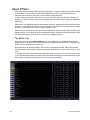
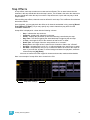
About Effects . . . . . . . . . . . . . . . . . . . . . . . . . . . . . . . . . . . . . . . . .102
The Effect List . . . . . . . . . . . . . . . . . . . . . . . . . . . . . . . . . . . . .102
Effects Editor . . . . . . . . . . . . . . . . . . . . . . . . . . . . . . . . . . . . . .103
Effect Status Display . . . . . . . . . . . . . . . . . . . . . . . . . . . . . . . .106
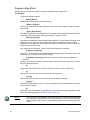
Step Effects . . . . . . . . . . . . . . . . . . . . . . . . . . . . . . . . . . . . . . . . . .107
Program a Step Effect . . . . . . . . . . . . . . . . . . . . . . . . . . . . . . .108
Absolute Effects . . . . . . . . . . . . . . . . . . . . . . . . . . . . . . . . . . . . . . .109
Relative Effects . . . . . . . . . . . . . . . . . . . . . . . . . . . . . . . . . . . . . . .109
Apply an Existing Effect . . . . . . . . . . . . . . . . . . . . . . . . . . . . . . . . .110
Editing Effects Live . . . . . . . . . . . . . . . . . . . . . . . . . . . . . . . . .110
Stop an Effect . . . . . . . . . . . . . . . . . . . . . . . . . . . . . . . . . . . . .110
Deleting an Effect . . . . . . . . . . . . . . . . . . . . . . . . . . . . . . . . . .110
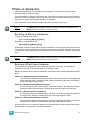
Effects on Submasters . . . . . . . . . . . . . . . . . . . . . . . . . . . . . . . . . .111
Recording an Effect to a Submaster . . . . . . . . . . . . . . . . . . . .111
Running an Effect from a Submaster. . . . . . . . . . . . . . . . . . . .111
Appendix A
Important Concepts . . . . . . . . . . . . . . . . . 113
Important Concepts . . . . . . . . . . . . . . . . . . . . . . . . . . . . . . . . . . . .113
Channel . . . . . . . . . . . . . . . . . . . . . . . . . . . . . . . . . . . . . . . . . .113
Address . . . . . . . . . . . . . . . . . . . . . . . . . . . . . . . . . . . . . . . . . .113
Record Target . . . . . . . . . . . . . . . . . . . . . . . . . . . . . . . . . . . . .113
v
Cue . . . . . . . . . . . . . . . . . . . . . . . . . . . . . . . . . . . . . . . . . . . . .113
Move Instruction and Track . . . . . . . . . . . . . . . . . . . . . . . . . . .113
Tracking vs. Cue Only . . . . . . . . . . . . . . . . . . . . . . . . . . . . . . .114
Move Fade. . . . . . . . . . . . . . . . . . . . . . . . . . . . . . . . . . . . . . . .114
HTP vs. LTP . . . . . . . . . . . . . . . . . . . . . . . . . . . . . . . . . . . . . .114
Syntax Structure . . . . . . . . . . . . . . . . . . . . . . . . . . . . . . . . . . .115
Parameters and Parameter Categories . . . . . . . . . . . . . . . . . .116
Live and Blind . . . . . . . . . . . . . . . . . . . . . . . . . . . . . . . . . . . . .116
Appendix B
Setup . . . . . . . . . . . . . . . . . . . . . . . . . . . . 117
Overview . . . . . . . . . . . . . . . . . . . . . . . . . . . . . . . . . . . . . . . . . . . 117
Opening Setup . . . . . . . . . . . . . . . . . . . . . . . . . . . . . . . . . . . . . . . 117
Appendix C
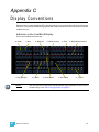
Display Conventions . . . . . . . . . . . . . . . . . 123
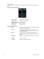
Indicators in the Live/Blind Display . . . . . . . . . . . . . . . . . . . . .123
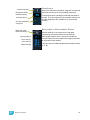
Indicators in the Playback Status Display . . . . . . . . . . . . . . . .127
Indicators in the Fader Bar Display . . . . . . . . . . . . . . . . . . . . .128
Appendix D
Remote Control. . . . . . . . . . . . . . . . . . . . . 129
Remotes Overview . . . . . . . . . . . . . . . . . . . . . . . . . . . . . . . . . . . . 129
vi
Element User Manual
Introduction
Welcome to the Element User Manual. This guide is a basic resource for users of the Element
control system. Additional resources available to you are listed in this introduction.
This chapter contains the following sections:
Introduction
•
Welcome to Element . . . . . . . . . . . . . . . . . . . . . . . . . . . . . . . . .2
•
Using this Manual . . . . . . . . . . . . . . . . . . . . . . . . . . . . . . . . . . .2
•
Register Your Element . . . . . . . . . . . . . . . . . . . . . . . . . . . . . . .3
•
Help from ETC Technical Services. . . . . . . . . . . . . . . . . . . . . .4
•
Other Reference Materials . . . . . . . . . . . . . . . . . . . . . . . . . . . .5
•
Online Element User Forums . . . . . . . . . . . . . . . . . . . . . . . . . .3
1
Welcome to Element
Thank you for purchasing the Element Lighting Control Console from ETC! This introduction to
Element will list all the various helpful tools available to you. In addition to this User Manual,
Element also has video tutorials, an online user forum dedicated completely to Element, and
support from ETC Technical Services. When using Element, you are never alone. Please take a
moment to learn more about the tools available to you.
Using this Manual
In order to be specific about where features and commands are found, the following naming and
text conventions will be used:
•
Facepanel buttons are indicated in bold [brackets]. For example, [LIVE] or [Enter].
Optional keys are indicated in <angle brackets>, for example, <Cue> or <Sub>.
•
Browser menus, menu items, and commands you must perform are indicated in bold
text. For example: In the File menu, click Open. Or: Press [Record] [Enter].
•
Alphanumeric keyboard buttons are indicated in all CAPS. For example, TAB or CTRL.
• Keys which are intended to be pressed or held simultaneously are indicated with the “and”
symbol. For example, [Update] & [Select].
•
Softkeys and clickable buttons in the Central Information Area (CIA) are indicated in
bold {braces}. A note about <More SK> (more softkeys): this command is always
indicated as optional, and is only indicated once in an instruction regardless of how
many pages of softkeys exist. This is because there is no way to predict what softkey
page you are on at any given time. Press <More Softkeys> until you find the required
command.
•
References to other parts of the manual are indicated in italics. When viewing this
manual electronically, click on the reference to jump to that section of the manual.
Note:
Notes are helpful hints and information that is supplemental to the main text.
CAUTION:
A Caution statement indicates situations where there may be undefined or
unwanted consequences of an action, potential for data loss or an equipment
problem.
WARNING:
A Warning statement indicates situations where damage may occur, people may
be harmed, or there are serious or dangerous consequences of an action.
Please email comments about this manual to: [email protected]
2
Element User Manual
Register Your Element
Registering your Element system with ETC ensures that you will be notified of software and library
updates, as well as any product advisories.
When you register, you will also be enrolled in “My ETC,” a personalized ETC Web site that
provides a more direct path of communication between you and ETC.
Register now at http://www.etcconnect.com/product.registration.asp.
Online Element User Forums
You are encouraged to visit and participate in the ETC Element User Forum, accessible from the
ETC web site (www.etcconnect.com). This gives you access to an online community of Element
users where you can read about other users’ experiences, suggestions, and questions regarding
the product as well as submit your own.
To register for the ETC Element User Forum:
Step 1:
Step 2:
Step 3:
Introduction
Go to ETC’s community web site (www.etcconnect.com/community). An introduction
page to the online community will open.
You may register for the forum using the “register” link in the introduction or by
clicking the “join” link in the upper right corner of the page.
Follow the registration instructions provided by the community page.
3
Help from ETC Technical Services
If you are having difficulties, your most convenient resources are the references given in this user
manual. To search more widely, try the ETC Web site at www.etcconnect.com. If none of these
resources is sufficient, contact ETC Technical Services directly at one of the offices identified below.
Emergency service is available from all ETC offices outside of normal business hours.
When calling for assistance, please have the following information handy:
•
Console model and serial number (located on back panel)
•
Dimmer manufacturer and installation type
•
Other components in your system (Unison®, other consoles, etc.)
Americas
Electronic Theatre Controls Inc.
Technical Services Department
3031 Pleasant View Road
Middleton, WI 53562
800-775-4382 (USA, toll-free)
+1-608 831-4116
[email protected]
Asia
Electronic Theatre Controls Asia, Ltd.
Technical Services Department
Room 1801, 18/F
Tower 1, Phase 1 Enterprise Square
9 Sheung Yuet Road
Kowloon Bay, Kowloon, Hong Kong
+852 2799 1220
[email protected]
4
United Kingdom
Electronic Theatre Controls Ltd.
Technical Services Department
26-28 Victoria Industrial Estate
Victoria Road,
London W3 6UU England
+44 (0)20 8896 1000
[email protected]
Germany
Electronic Theatre Controls GmbH
Technical Services Department
Ohmstrasse 3
83607 Holzkirchen, Germany
+49 (80 24) 47 00-0
[email protected]
Element User Manual
Other Reference Materials
On Screen Prompts
Element provides on screen prompts located above the command line to aid with programming.
These context-sensitive prompts will give instructions and options based on the current display and
key hits.
Help System
A help system is also contained within your Element console. To access help, press and hold [Help]
and press any key to see:
•
•
•
the name of the key
a description of what the key enables you to do
syntax examples for using the key (if applicable)
Note:
Help is included on most tangible action buttons on your Element console. This
includes most softkeys and clickable buttons as well as the traditional keys on the
keypad.
As with hard keys, the “press and hold [Help]” action can be also used with
softkeys and clickable buttons.
Important Lighting Concepts
In addition to Element’s video tutorials, ETC also has a video explaining the important lighting
concepts of tracking and preset. If you are new to lighting consoles, it is highly recommended that
you take a few moments and view this video.
Additional lighting concepts are also explained in this User Manual, please see Important Concepts,
page 113 to learn more.
Periodic Table of Element
The Periodic Table of Element is a handy reference guide for the various concepts and components
of Element. Please visit the Periodic Table of Element.
I o n O p e r a t i o n s Ma n u a l
The Element User Manual is a beginning guide to the Element Lighting Control Console. For more
in depth discussion of topics covered here or for more advanced features of Element, such as show
control, please see the Ion Operations Manual. The Ion Operations Manual is available as a pdf on
the Element Tutorial CD or for download from www.etcconnect.com.
Quick Start
To quickly get started with Element, please See “Quick Start” on page 7. For more in depth
information about Element, please continue reading this User Manual.
Introduction
5
6
Element User Manual
Chapter 1
Quick Start
This chapter will walk you through the steps of quickly getting started with Element.
This chapter contains the following sections:
1
Quick Start
•
Getting Started . . . . . . . . . . . . . . . . . . . . . . . . . . . . . . . . . . . . . .8
•
Hardware . . . . . . . . . . . . . . . . . . . . . . . . . . . . . . . . . . . . . . . . . .8
•
Getting the Lights On . . . . . . . . . . . . . . . . . . . . . . . . . . . . . . . .9
•
Recording a Lighting Look . . . . . . . . . . . . . . . . . . . . . . . . . . .10
7
Getting Started
This chapter will quickly get you started with using Element. Later chapters will go into further detail
of topics touched upon here.
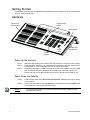
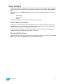
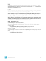
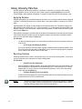
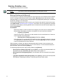
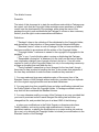
Hardware
Fader Position
Switch
Faders and
bump buttons
Power button
Control
keypad
Level
wheel
Blackout and
Grandmaster
Power Up the Console
Step 1:
Step 2:
Step 3:
Attach the appropriate power cable to the IEC connector on the rear of the console.
Press the power switch (I is “on”) under the IEC connector on the rear of the console
to turn power on. This will provide power to all internal electronics.
Press the power button, located in the top left corner of the console, above the USB
port. The button LED will illuminate blue to indicate the console is running. The
console will boot up into the Element environment. Element is now ready for use.
P o w e r D o w n th e C o n s o l e
Step 1:
Step 2:
Note:
8
In the browser menu select File>Power Off Console. A dialogue box opens asking
you to confirm.
Confirm this command by pressing [Select] or clicking with a mouse the {OK} button
in the dialog box. The console will power down.
For additional information on setting up Element’s hardware, please see the
Element Setup Guide.
Element User Manual
Getting the Lights On
When Element first boots up, it will default to a 1-to-1 patch. See About Patch, page 32 for more
information. Since Element starts off patched, you can begin bringing up levels immediately.
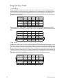
Setting Levels Via Channel Faders
For more in depth information on using Element’s channel faders, see Using Channel Faders, page
40.
Step 1:
Check to make sure the Fader Position Switch is set to Channel 1-40. The first two
rows of faders will then control channels 1-40. 1-20 will be controlled by the first bank
and 21-40 by the second bank.
Make sure Element is displaying in Live. Press [Live].
Check to make sure the Grandmaster is at 100%. The top of Element’s display will
show Grandmaster #% in red if the Grandmaster is below 100%.
Check to make sure the Blackout key is not lit. It is located directly above the
Grandmaster.
You can now raise one or more channel faders to control channels 1-40.
Step 2:
Step 3:
Step 4:
Step 5:
Note:
Use the Fader Position Switch to change the channels the faders will control. The
first 120 channels can be controlled via the faders. Channel 121 and above must
be controlled from the keypad.
Step 6:
Lower the faders as needed to fade out channel levels.
Setting Levels Via the Control Keypad
For more information about the control keypad, see Selecting Channels, page 41.
Step 1:
Step 2:
Step 3:
Step 4:
•
•
•
•
Note:
1
Quick Start
Make sure Element is displaying in Live. Press [Live].
Check to make sure the Grandmaster is at 100%. The top of Element’s display will
show Grandmaster #% in red if the Grandmaster is below 100%.
Check to make sure the Blackout key is not lit. It is located directly above the
Grandmaster.
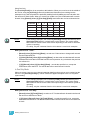
You can now set levels from the keypad. Here are some examples of the syntax
needed:
[5] [Full] [Enter] - sets channel 5 to 100% or Full.
[1] [Thru] [1] [0] [At] [7] [5] [Enter] - selects a range of channels 1 through 10 and
sets their level to 75%.
[2] [+] [7] [At] [2] <0> [Enter] - selects channels 2 and 7 and sets their levels at
20%.
[5] [0] [Thru] [7] [0] [-] [6] [0] [At] [5] <0> [Enter] - selects channels 50 through
70, except 60, and sets their levels to 50%.
[Enter] must be used at the end of the command to terminate the command line.
Levels will not be set until the command line has been terminated.
9
Step 5:
•
•
•
•
•
To remove a channel’s level, you can either use the command [At] [Enter], or you can
use [Sneak] [Enter]. If you have no recorded any lighting looks yet, [At] [Enter] sets
the level to 0%, while [Sneak] [Enter] takes the level completely out.
[1] [0] [At] [Enter] - sets the level of channel 10 to 0%.
[Sneak] [Enter] - fades out all manual levels.
[5] [Sneak] [Enter] - fades out the manual level for channel 5.
[1] [Thru] [1] [0] [At] [Enter] - sets the levels for channels 1 through 10 to 0%.
[2] [0] [Thru] [2] [5] [Sneak] [Enter] - fades out the levels for channels 20 through
25.
Recording a Lighting Look
Often times you will want to create and recall a lighting look. Submasters and cues are two ways
that you can record looks to be able to recall them. This quick start will only cover recording
submasters.
Recording a Submaster
For more information about submasters, see Storing and Using Submasters, page 49.
Step 1:
Step 2:
Note:
Step 3:
Step 4:
Set the channel levels that you want in your look using the channel faders and/or
keypad.
Switch the Fader Position Switch to Submaster mode.
If you have an Element 60 console, the third bank of faders are always in
submaster mode.
Press [Record] then the bump button of the submaster you wish to record. This
action will terminate the command line so there is no need to hit [Enter]. You can also
record a submaster using the following syntax, [Record] [Sub] [#] [Enter], in case
you don’t want to jump to submaster mode on the faders.
You can either leave that look up and build upon it or use [Sneak] [Enter] to fade out
the manual levels.
If you would like to record looks to be able to play them back using Element’s [Go] button, please
see Basic Cueing, page 58.
10
Element User Manual
Chapter 1
Element Overview
Inside this chapter you will find a general overview of your Element control console.
This chapter contains the following sections:
1
•
Console Geography. . . . . . . . . . . . . . . . . . . . . . . . . . . . . . . . .12
•
Control Keypad Layout . . . . . . . . . . . . . . . . . . . . . . . . . . . . . .13
•
Terminology . . . . . . . . . . . . . . . . . . . . . . . . . . . . . . . . . . . . . . .14
•
Cleaning Element. . . . . . . . . . . . . . . . . . . . . . . . . . . . . . . . . . .14
•
Outputting DMX . . . . . . . . . . . . . . . . . . . . . . . . . . . . . . . . . . . .14
•
Console Capacities . . . . . . . . . . . . . . . . . . . . . . . . . . . . . . . . .15
Element Overview
11
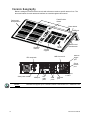
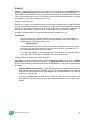
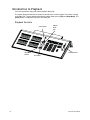
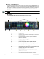
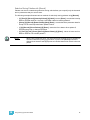
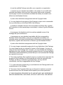
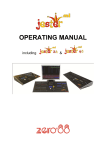
Console Geography
Below is a diagram of the Element console with references made to specific areas of use. The
terms and names for each area and interface are used throughout this manual.
Fader Position
Switch
Faders and
bump buttons
Power button
USB port
Playback
controls
Level
wheel
Control
keypad
Blackout and
Grandmaster
Remote
trigger
port
MIDI Out and In
IEC receptacle
Phone
remote
port
Hard power switch
Note:
12
VGA port
DVI
video
ports
DMX ports
1 and 2
USB
ports
Ethernet
port
Element can support up to 2 monitors, either 2 DVI monitors or 1 VGA and 1 DVI.
Element User Manual
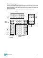
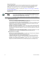
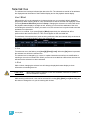
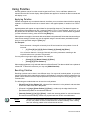
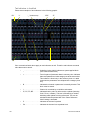
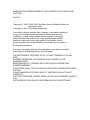
Control Keypad Layout
The control keypad area is divided into several sections including record targets, numeric keypad
with modifiers, display, softkeys, navigation, and special function controls.
Display and navigation keys are used for quick access to common displays, format, paging, and
navigation within displays.
The load button is located above the fader pair and is used to load the specified cue.
Display
ll
Softkeys
Special
function
controls
Navigation
Record targets
and related
commands
1
Element Overview
Numeric Keypad and
modifiers
13
Terminology
Pow e r Button
The power button on the front of the console is used to power up the Element console. A separate
power switch, located in the rear panel of the console, can be used to disconnect power from the
console’s internal components.
WARNING:
Before servicing the Element control console, you must switch off the
power from the rear of the console and disconnect the power cord
completely.
US B Ports
One USB port is provided on the front of the console to connect any USB storage device. Additional
USB ports on the rear panel of the console can be used to connect peripherals such as an
alphanumeric keyboard, pointing device, or touchscreen control for external monitors.
Level Wheel
Proportionally adjusts intensity for selected channels. It also provides scrolling and zoom functions
in various modes.
IEEE Ethernet 802.3 Ethernet Port
Ethernet port for connection to a network switch, network gateways, and accessory devices.
Littlites®
You may connect a Littlite to the side of your Element console.
Cleaning Element
Should the exterior of your Element require cleaning, you may gently wipe it with a dampened (not
dripping), non-abrasive paper towel or soft cloth.
If this does not clean the console sufficiently, you may apply some window cleaner (containing
ammonia is fine) to the cloth and repeat the process until clean.
O u t p u t ti n g D M X
In order to output control levels from Element, you can either use the DMX ports on the back of the
console, or to output over a network, you may connect a Net3 gateway or Net2 node. If your device
receives Net3 or ETCNet2 directly, no gateway or node is required.
Element has two DMX ports. To output, connect one 5 pin XLR cable per port. The first port will
output the first universe of DMX, addresses 1-512, and the second port is the second universe,
outputting addresses 513-1024.
Nodes and gateways must be given an IP address before they can function with Element. This may
require using NCE (Network Configuration Editor) or GCE (Gateway Configuration Editor) and a
Windows® PC to configure the gateways or nodes. The NCE or GCE Software CD and related user
manuals and setup guides were packaged with your gateway or node. Use these materials to
prepare them for use with Element.
For more information on Net3 gateways or Net2 nodes, see the product literature that accompanied
the hardware or download it from our website at www.etcconnect.com.
14
Element User Manual
Console Capacities
Output Parameters
• 1,024 Outputs (DMX channels)
Channel Counts
• 250 or 500 Channels
Cues and Cue Lists
• Up to 10,000 cues
• 1 Active Playback
• 1 Cue List
Record Targets
• 1,000 Groups
• 1,000 x 4 Palettes (Intensity, Focus, Color and Beam)
• 1,000 Curves
• 1,000 Effects
• 1,000 Macros
Faders
• 1 Grandmaster with Blackout
• 1 Master Playback, with Go and Stop/Back
• 40 or 60 Faders with bump buttons
• a maximum of 300 configurable submasters
• 120 channel faders
1
Element Overview
15
16
Element User Manual
Chapter 2
System Basics
This chapter will discuss using the basic Element displays.
This chapter contains the following sections:
2
System Basics
•
The Central Information Area (CIA) . . . . . . . . . . . . . . . . . . . .18
•
Using Softkeys . . . . . . . . . . . . . . . . . . . . . . . . . . . . . . . . . . . . .19
•
Using the Browser . . . . . . . . . . . . . . . . . . . . . . . . . . . . . . . . . .20
•
Display Control and Navigation . . . . . . . . . . . . . . . . . . . . . . .21
•
Using [Format] . . . . . . . . . . . . . . . . . . . . . . . . . . . . . . . . . . . . .23
17
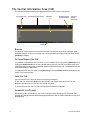
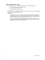
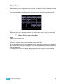
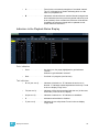
The Central Information Area (CIA)
The Central Information Area (CIA) is displayed on the lower portion of the screen.
Command Line
Command Line Prompt
Browser
Double arrows
CIA show/hide
CIA lock
(shown
unlocked)
Softkeys
Browser
The browser is the interface for numerous functions including saving a show, opening a show,
changing settings, viewing record target lists, opening displays and many other functions. Press
[Browser] to display.
Collapse/Expand the CIA
It is possible to collapse the CIA from view. You can collapse the CIA by pressing [Browser] or by
clicking the double arrow icon on the right side above the CIA. The CIA will collapse from view,
exposing a larger viewing area of whatever display is visible above the CIA. The double arrows will
move to the bottom of the screen.
To expand the CIA into view again, press [Browser] or click the double arrow at the bottom of the
screen. The CIA will reopen.
Lock the CIA
You can lock the CIA in place to prevent it from being collapsed.
To lock the CIA, click on the lock above the browser. The double arrow above the CIA will
disappear and the lock will “lock” the CIA to hold it in place.
To unlock the CIA, click the lock again and the double arrows will reappear.
Command Line Prompt
Directly above the command line, you will see red text that will prompt you for an action. The
prompts will change between different displays and actions, and are useful information to aid you in
programming.
18
Element User Manual
Using Softkeys
Some of the features and displays in Element are accessible from the softkeys, which are located
in the bottom right area of the CIA. Those softkeys correspond to buttons [S1] - [S6] and [More
SK].
Remember the use of the [Browser] button. This button offers softkeys that access the following
displays:
•
•
•
Effect Status
Show Control
Curves
Each of these displays offers its own specific softkeys of relevance.
Context Sensitive Softkeys
Softkeys are context sensitive and will change depending on a number of factors including: the
active display, the current command line, the active record target, and so on. Element always
repaints the softkeys to coincide with your current action.
To get the full use of features on your Element system, be sure to familiarize yourself with the
softkeys that become available as you program your show.
Changing Softkey Pages
When there are more relative softkeys than the six available softkey buttons, the LED in the [More
SK] button will light. Press [More SK] to view the additional softkeys.
2
System Basics
19
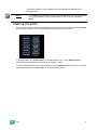
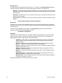
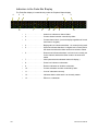
Using the Browser
To use the browser, you must first draw focus to it by pressing the [Browser] key.
When focus is on the browser, the window border highlights in gold. The scroll lock LED illuminates
red and the paging keys will now control selection in the browser.
Menu arrows
Opened menu
Selection bar
Sub menus
Scroll bar
• Use the page arrow keys to move the selection bar up and down the list. You can also use the
level wheel to scroll through the list.
• When the bar highlights the desired menu, press [Page X] to open the menu.
• Continue pressing [Page X] to open submenus.
• Scroll to the item you wish to open using [Page S] or [Page T] and then press [Select]. You
may also click the item you wish to open and then press [Select]. You can also use the level
wheel to scroll in the browser.
• If you wish to close a submenu scroll to that item and press [Page W].
• To draw focus to the browser at any time, press the [Browser] key.
Virtual Keyboard
It is possible to open a virtual keyboard in the CIA which mimics the hard keys found on the actual
Element keypad. This virtual keyboard is accessible from the browser.
The virtual keyboard is found with the other virtual controls in the browser. Navigate to
Browser>Virtual Controls>Virtual Keyboard.
This will give you click access to the Element hardkeys on the CIA. The browser and parameter
display will be hidden from view while the virtual keyboard is open. To close the virtual keyboard,
press the [Browser] button.
20
Element User Manual
Display Control and Navigation
Opening and Closing Displays
Displays can be opened and closed in different ways, depending on the display. Many displays are
accessible from Element’s keypad, while other displays are accessible from the browser and
softkeys. The blind displays of record targets (also called “lists”) can be quickly accessed by double
pressing the record target button, such as [Cue][Cue] will display the cue list.
From the hardkeys
Several displays are opened directly from buttons on Element’s keypad. Those displays are Live,
Blind, Patch, Setup, Park, Browser, and ML Control. You can open list views of any record target by
double-pressing the key for the desired record target
From the browser
Open and navigate the browser as described in Using the Browser, page 20. When you open a new
display (such as the cue list index or group list), it will open on the primary display. If the display
does not open to a monitor (such as setup or the browser) it will open in the CIA. Some displays are
available from the softkeys when the [Browser] button is pressed.
Again, any time you wish to return to the browser, simply press [Browser].
Closing Displays
To close any display:
• Press the [Browser] key again to open a different display.
• Press [Escape] to close the active display. The screen will return to live or blind.
• Press [Live] or [Blind] to replace the display with the live/blind view.
To close a display in the CIA, press the [Browser] key and the browser will reappear.
Swap Displays
When using two monitors, you can swap displays between monitors by pressing the [Swap] key.
Press it again to return to the original configuration.
2
System Basics
21
Scrolling within a Display
By default the page keys will advance/retreat a display by one page per press. However, to scroll
through displays you may press the [Scroll Lock] key on the keypad. The LED on the button
illuminates red when in scroll lock mode.
Scroll lock is a toggle state. When scroll lock is first pressed:
• [Page T] - scrolls table, spreadsheet and channel views down,
• [Page S] - scrolls table, spreadsheet and channel views up,
• [Page X] - scrolls table and spreadsheet views right,
• [Page W] - scrolls table and spreadsheet views left.
[Data] Key
Pressing and holding [Data] allows you to view the values behind any referenced or marked data.
[Data] exposes the next lower reference level. So if you view a palette reference and press [Data],
the absolute data will be displayed instead.
[Label] Key
Element allows for labeling of cues, channels, submasters, and more. Below are some examples of
labeling syntax:
Note:
You will need a mouse, keyboard, or touchscreen to create labels.
• [Cue] [6] [Label] <name> [Enter]
• [Group] [3] [Label] <name> [Enter]
• [Sub] [8] [Label] <name> [Enter]
If you press the label key for a target already labeled, this posts the current label to the command
line. To clear, press [Label] again. You can [Clear] to backspace one character at a time, or type to
append to the existing label.
[Recall From], [Copy To], {Replace With}, and {Move To}
[Recall From], [Copy To], {Replace With}, and {Move To} may be used to create and edit data.
See the Ion Operations Manual for more information.
22
Element User Manual
Using [Format]
Some displays have multiple formats. When the display is first opened, it opens in its default view.
The default view for Live/Blind is table view. Pressing [Format] will toggle between table, summary,
and, if in Blind, spreadsheet views.
Live and Blind share formatting. When you change from one format to another format, you are
always working with the same format until you change it. The exception to this is spreadsheet,
which is only available in blind. If you are working in blind spreadsheet, when you return to live you
will be working with the table or summary view, based on which one you were last using.
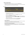
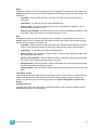
Table View
Table view is available in live or blind. If devices other than dimmers are patched, table view
displays the fixture type associated with channels and details about each channel’s category and
parameter levels.
In live, table view displays all active channel data being output from Element. In blind, it will display
all data for a single record target (cue, palette).
In the table view, a slight space is provided between fixture types, giving a clear delineation
between them. The name of the fixture type is displayed at the top of the section for that fixture.
Parameter data
Fixture type
Live Table View
2
System Basics
23
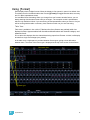
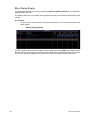
Summary View
The summary view displays the largest number of channels of any of the formats. Below you can
see channels 1-80 are shown. This format is best used to see large numbers of channels’ intensity
data or parameter category data. Individual non-intensity parameters are not visible in this view.
Channel numbers
Intensity data
F, C, B data
Z o o m i ng D i s p l a y s
You may zoom the table and summary view to display more or less channels. To do this, press and
hold the [Format] button and scroll the Level Wheel to alter the number of channels visible.
Scrolling the wheel up zooms in. Scrolling the wheel down zooms out. Zooming this display when
it is in 100 channel mode is not supported. A scroll wheel on a mouse can also control zooming.
24
Element User Manual
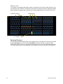
Spreadsheet (Blind Only)
Spreadsheet format is available only in blind mode. It is useful for viewing and editing channel data
and trends for multiple cues, submasters, or palettes at one time. Cues and other record targets are
displayed on the vertical axis and channel data is visible on the horizontal axis. See “Recording and
Editing Cues from Blind” on page 72.
To just view intensity information, click {Hide NPs}. If the parameters are already hidden, click
{Show NPs} to view.
Cue numbers
2
Channel number
System Basics
Parameters
25
26
Element User Manual
Chapter 3
Managing Show Files
This chapter explains how to create, open, and save your show files. Each of these operations are
accomplished through the browser area.
This chapter contains the following sections:
3
•
Create a New Show File. . . . . . . . . . . . . . . . . . . . . . . . . . . . . .28
•
Open an Existing Show File . . . . . . . . . . . . . . . . . . . . . . . . . .28
•
Saving the Current Show File . . . . . . . . . . . . . . . . . . . . . . . . .30
•
Using Save As . . . . . . . . . . . . . . . . . . . . . . . . . . . . . . . . . . . . .30
Managing Show Files
27
Create a New Show File
To create a new show file, navigate within the browser to: File> New> and press [Select].
You will be prompted for confirmation that you want to reset the system. Press [Select] or click
{OK} to confirm or {Cancel} to discontinue the operation.
In Element, a new show file defaults to a 1 to 1 patch. Clicking {Patch 1to1} will deselect the option
and result in a blank patch.
Show File Names
Names of show files may appear in the browser list in normal text or in bold text. Files in normal
text indicate that there is only one show file stored by that name.
Bold show names indicate that there are several versions of the show file stored under that name,
the bold one being the most recent. To access the most recent show file, simply select the bold
name. You may right arrow [t] from the bold name to expand a list of previous versions beneath it
in the browser. Select the desired show from the expanded list.
Open an Existing Show File
To open an existing Element show file, navigate within the browser to: File> Open> and press
[Select].
Element provides you with multiple locations to retrieve an Element show file (.esf) including:
• Show File Archive - This is the default storage location for show files when a show file is
created and saved. Folders are automatically created to store older versions of a show file.
This allows you the ability to open the latest version or an earlier version of a show file if
desired.
• File server - if one is connected. When there is no file server connected, it will not display in
the browser.
• USB (E:) device - When a USB device is connected and an Element show file (.esf) is
available on the device, you will notice the USB is displayed in white text and is expandable.
When the USB device is connected and no Element show file is loaded on the device, you will
notice the USB (F:) is displayed in a grey color and is not selectable.
Open the desired location:
• To open a show file from the Show File Archive, navigate within the browser to: File> Open>
Show File Archive and press [Select].
• To open a show file from the file server, navigate within the browser to: File > Open> File
Server> and press [Select].
• To open a show file from a USB device, navigate within the browser to: File> Open> USB (E:)
and press [Select].
28
Element User Manual
Select the specific show file
• Navigate within the specified storage location and select the show file you wish to open, press
[Select].
• If the selected show has multiple time stamps, navigate to the desired revision and press
[Select].
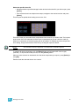
This will open the partial show loading screen in the CIA.
From this screen you can select which components of the show file you wish to load. The buttons
at the center of the CIA represent all of the show components that you can choose to load. By
default all components are selected (gray) and will be loaded. To withhold any show components
from loading, simply deselect them in the CIA by clicking the respective button.
Note:
You will need a mouse, keyboard, or touchscreen to deselect options.
To reselect all show components, click the {Reset} button and all buttons will return to gray
(selected). To stop the show load process, click the {Cancel} button.
When you have selected or deselected all of the show components you require, press [Select] or
click {OK}.
Element loads the selected show to the console.
3
Managing Show Files
29
Saving the Current Show File
To save the current show data, navigate within the browser to: File> Save> and press [Select].
The Show File Archive is the default storage location for show files when they are saved. The new
time stamp located beneath the show file name on the CIA indicates that the show file has been
saved.
All previous saves are stored in the Show File Archive with the time stamp following the file name.
Note:
When saving a show file for the first time, Element will provide the name "Show
File" and will attach a time/date stamp to the name. To change the name, use a
mouse and the on-screen keyboard, or an attached USB keyboard.
Using Quick Save
To save the current show data to the hard drive without having to navigate to the browser, hold
down [Update] and press [Select].
Using Save As
To save an existing Element show file to a different location or with a different name, navigate within
the browser to: File> Save As> and press [Select].
Element provides you with three locations to save an Element show file (.esf) including the Show
File Archive, the File Server (if connected) or a USB device (if connected).
Navigate to the desired storage location and press [Select]. When using “Save As” to save the
show file to a specific location, the alphanumeric keypad will display on the CIA. Name the show file
and press [Enter]. The show file will be saved in the specified location with the show file name you
entered with a time stamp suffix.
Deleting a File
Element provides you with the ability to delete show files from the Show File Archive and the File
Server from within the browser.
To Delete a Show File
Navigate within the browser to: File> Open and press [Select]. Navigate to the desired show file
and press [Delete]. Press [Enter] to confirm or any other key to abort the deletion process.
30
Element User Manual
Chapter 4
Patch
The Patch is used to associate a channel with an address. Once a channel is patched to an
address, and the output is connected to a device (for example a dimmer, moving light, or
accessory), the channel will then control that device.
This chapter contains the following sections:
4
Patch
•
About Patch . . . . . . . . . . . . . . . . . . . . . . . . . . . . . . . . . . . . . . .32
•
Displays . . . . . . . . . . . . . . . . . . . . . . . . . . . . . . . . . . . . . . . . . .32
•
Patching a Dimmer By Address . . . . . . . . . . . . . . . . . . . . . . .33
•
Patching a Dimmer By Channel . . . . . . . . . . . . . . . . . . . . . . .33
•
Patching a Scroller . . . . . . . . . . . . . . . . . . . . . . . . . . . . . . . . .35
•
Patching Accessories, LEDs, and Moving Lights. . . . . . . . .36
•
Clearing the Patch . . . . . . . . . . . . . . . . . . . . . . . . . . . . . . . . . .37
31
About Patch
When you open a new show file, Element creates a 1-to-1 patch. This means that the patch will
automatically have channel 1 patched to address 1, channel 2 to address 2, and so on up to the
maximum channel count of your console.
Depending on your situation, you may need to create a custom patch, which associates certain
addresses with certain channels.
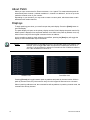
Displays
To begin patching your show, you must first open the patch display. Press the [Patch] button to
open the display.
The patch display will open on the primary display and the CIA will display the patch controls. By
default, patch is displayed in a sequential address view. While in the patch by address view, any
initial numeric entry from the keypad is assumed to be an address.
As it is possible to patch by either address or port/offset, pressing the [Data] key will toggle the
display to show the alternate output information.
Note:
Port/offset refers to the DMX universe or port and the offset of the address. For
example, since a single DMX cable can transmit 512 addresses (known as a
“universe”), the port/offset for address 515 would look like 2/3 because address
515 is the 3rd address of universe 2.
Address view
Port/Offset view
Pressing [Format] will toggle between patch by address and patch by channel modes. While in
patch by channel mode, any initial numeric entry from the keypad is assumed to be a channel.
When in patch by address mode, the command line will say address. In patch by channel mode, the
command line will say channel.
32
Element User Manual
Patching a Dimmer By Address
Tutorial
Step 1:
Step 2:
Step 3:
Note:
To patch a dimmer you must first open the patch display. Press the [Patch] button.
Enter an address number from the control keypad.
• When typing any number from the control keypad, and patch is in default
address mode, address is assumed and is placed on the command line.
Enter the channel or channels.
• Press [At] and enter the channel using the control keypad.
• Multiple addresses may be patched to a channel in a single command. For
example, [1] [0] [5] [+] [2] [0] [5] [+] [3] [0] [5] [At] [1] [0] [Enter] would patch
address 105, 205, and 305 to channel 10. When more than one device is
patched to a channel, Element automatically creates parts for each device. This
is used if you need to access an address directly in the patch-by-channel
display.
If at any point you try to patch an address that is already in use, Element will post
an advisory to indicate this, preventing you from duplicating addresses in your
patch. Element will only patch an address to a single channel at a time.
Patching a Dimmer By Channel
Tutorial
Step 1:
Step 2:
Step 3:
Step 4:
To patch a dimmer, you must first open the patch display. Press the [Patch] button.
To patch by channel, you must press [Format].
Enter a channel number from the control keypad.
• When typing any number from the control keypad, and patch is in channel
mode, channel is assumed and is placed on the command line.
• You can also use the [+], [-], and [Thru] keys to make your channel selection.
Enter the address or addresses.
• Press [At] and enter the address or addresses using the control keypad.
• You can also use the [+], [-], and [Thru] keys to make your address selection.
• Multiple addresses may be patched to a channel in a single command. For
example, [1][0] [At] [1][0][5] [+] [2][0][5] [+] [3][0][5] [Enter] would patch
address 105, 205, and 305 to channel 10. When more than one device is
patched to a channel, Element automatically creates parts for each device. This
is used if you need to access an address directly in the patch-by-channel
display.
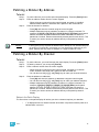
Status in the Patch Display
The first column in the patch display will advise you when a channel requires your attention.
•
4
Patch
“!” is displayed next to a channel number when there is a problem with the patch or to
indicate there is an error.
33
Patching a Compound Channel
A compound channel consists of any channel that controls more than one device. It can consist of
mutliple dimmers patched to the same channel or accessories patched to a channel (such as a
fixture with a color scroller, a fixture with a gobo wheel, and so on). By default, Element will add a
part if you are trying to patch to a channel that has already been assigned an address.
To patch a compound channel in address format:
•
[5] [1] [3] [At] [8] [Enter]
Assuming channel 8 was previously patched to an address, this will create a part 2 and
address it at 513.
To patch a compound channel in channel format:
•
[9] [At] [5] [4] [0]
Assuming that channel 9 is already patched to an address, this will create a part 2 and
address it at 540.
•
[8] [Part] [2] [At] [5] [1] [3]
This will create a part 2 for channel 8 and address it at 513. If you wish to patch by address
while in the channel view, press:
•
[Address] [5] [1] [3] [At] [8] [Enter]
This will perform the same action as the previous example, assuming channel 8 was
previously patched to an address.
CAUTION:
34
It is recommended that you do not patch more than one multiple-parameter device
(such as moving lights) to the same channel. Doing so can cause extreme
difficulty in controlling the devices.
Element User Manual
Patching a Scroller
Note:
Patching a scroller requires a mouse or touchscreen.
Tutorial
Step 1:
Step 2:
Step 3:
Follow the instructions for Patch by channel.
Add a part to the channel. See “Patching a Compound Channel” on page 34.
Select the part of the channel you wish to patch the scroller.
• [3] [Part] [2] [Enter] - selects part 2 of channel 3.
Click the {Type} button in the CIA.
Step 4:
a: Click {Manfctr} from the CIA to display the library. The two columns on the
left are pagable and show manufacturer names.
b: Use the arrow buttons to scroll the list of manufacturers. Selecting a
manufacturer repaints the device columns with all devices from that
manufacturer that are available for patching.
c:
Note:
Scroll through the device list and make your selection. After the selection is
made, the fixture or device type will be placed on the command line after the
channel number and displayed in the box beneath the {Type} button.
Notice the two softkeys {Show Favorites} and {Manfctr} located beneath the
CIA.
These softkeys provide you with the option of showing only the library of fixtures
or devices that are already patched in the show and your favorites/ Element
default devices, {Show Favorites}, or all fixtures or devices available in the library
sorted by manufacturer {Manfctr}.
{Show Favorites} will have a list of generic and commonly used devices.
Step 5:
Step 6:
Click the {Attributes} softkey.
Click on {Scroller} to assign a scroller.
• The Scroller/Wheel picker will display in the CIA. You can either select one of
the default scrollers or you can create your own scroller
.
Note:
4
Patch
For additional information on creating a custom scroller and/or calibrating a
scroller, please see the Patch section of the Ion Operations Manual.
35
Patching Accessories, LEDs, and Moving Lights
The process of patching moving lights requires more detail than patching a dimmer. Specific
information is required for more advanced control of the features offered by moving lights.
Note:
Patching accessories, LEDs, and Moving lights require a mouse or touchscreen.
Tutorial
Step 1:
Step 2:
Step 3:
Note:
Step 4:
Step 5:
To patch a moving light you must first open the patch display. Press the [Patch]
button.
Press [Format] to change the display to patch by channel mode.
Enter a channel number or multiple numbers from the control keypad.
• When typing any number from the control keypad, and patch is in default
channel mode, channel is assumed and is placed on the command line. You
can use the [+], [-] and [Thru] keys to make your channel selection.
For example: [1] [0] [1] [Thru] [1] [1] [0]
Alternatively, when patch is in address mode, DMX address is assumed and is
placed on the command line. Channel mode and address mode are toggled using
the [Format] key in the patch display.
Click the {Type} button in the CIA.
Select a device type from the fixture library.
a: Press {Manfctr} from the CIA to display the fixture library. The two columns
on the left are pagable and show manufacturer names.
b: Use the arrow buttons to scroll the list of manufacturers. Selecting a
manufacturer repaints the device columns with all devices from that
manufacturer that are available for patching.
c:
Note:
Scroll through the device list and make your selection. After the selection is
made, the fixture or device type will be placed on the command line after the
channel number and displayed in the box beneath the {Type} button.
Notice the two softkeys {Show Favorites} and {Manfctr} located beneath the
CIA.
These softkeys provide you with the option of showing only the library of fixtures
or devices that are already patched in the show and your favorites, {Show
Favorites}, or all fixtures or devices available in the library sorted by manufacturer
{Manfctr}.
Step 6:
Enter a starting address for the selected channel or group of channels.
• Press [At] and enter the address using the control keypad. The address may be
entered in standard format ([1] [0] [2] [5]) or by using port and offset ([3] [/] [1]).
Step 7: To select a device interface (optional), click {Interface}.
Step 8: Click the {Attributes} softkey to set detailed moving light attributes.
Step 9: The following buttons may be available on this page: {Invert Pan} and {Invert Tilt},
{Swap}, {Scroller}, {Gobo Wheel}, {Color Wheel}, {Preheat}, {Proportion}, and
{Curve}.
Step 10: If your moving light includes parameters such as a color scroller or gobo wheel and
you have custom gels or non-standard patterns installed, use the Scroller/Wheel
Picker and the Editor to modify the device patched. The more specific your patch data
36
Element User Manual
(including accurate colors and patterns) the more detailed programming and
operating will be.
Note:
For additional information on using the Scroller/Wheel picker or setting detailed
moving light attributes, please see the Patch section of the Ion Operations
Manual.
Clearing the Patch
You can clear the patch entirely by accessing the clear functions from the browser. Select {Clear}
from the main browser menu. The clear functions window will open in the CIA.
To clear the patch, click {Clear Patch}. To reset the patch to 1-to-1, click {Reset Patch}. A
confirmation is required before the patch will be cleared or reset.
To exit the clear functions screen without clearing, press the [Browser] key at any time or select a
clear button and then select {Cancel} from the confirmation screen.
4
Patch
37
38
Element User Manual
Chapter 5
Basic Manual Control
Element provides a variety of ways to select and command control channels. This chapter identifies
the many basic ways you can select channels and manipulate show data within Element.
This chapter contains the following sections:
5
•
Using Channel Faders . . . . . . . . . . . . . . . . . . . . . . . . . . . . . . .40
•
Selecting Channels . . . . . . . . . . . . . . . . . . . . . . . . . . . . . . . . .41
•
Setting Intensity . . . . . . . . . . . . . . . . . . . . . . . . . . . . . . . . . . . .43
•
Using +% and -% . . . . . . . . . . . . . . . . . . . . . . . . . . . . . . . . . . .45
•
Remainder Dim. . . . . . . . . . . . . . . . . . . . . . . . . . . . . . . . . . . . .46
•
Sneak . . . . . . . . . . . . . . . . . . . . . . . . . . . . . . . . . . . . . . . . . . . .47
•
Channel Check . . . . . . . . . . . . . . . . . . . . . . . . . . . . . . . . . . . . .48
•
Address at Level . . . . . . . . . . . . . . . . . . . . . . . . . . . . . . . . . . .48
•
Address Check. . . . . . . . . . . . . . . . . . . . . . . . . . . . . . . . . . . . .48
•
Moving Light Control. . . . . . . . . . . . . . . . . . . . . . . . . . . . . . . .48
Basic Manual Control
39
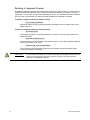
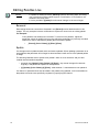
Using Channel Faders
One way to bring up channel levels with Element is using the channel faders. The fader position
switch is used to select between channels 1-40, channels 41-80, or channels 81-120. Element will
ship with the fader position switch in channels 1-40 mode.
Note:
Channel faders will only control the first 120 channels. Channels 121 and above
must be controlled via the keypad. See “Selecting Channels” on page 41.
Raising a channel fader will bring up the corresponding
channel’s level. This will be reflected on Element’s live
display. The channel intensity level will appear in red to
indicate the level is being set manually.
Intensity data
Element’s fader bar display will also show the channel’s
level. For more information, See “Indicators in the Fader
Bar Display” on page 128.
Element’s channel faders are LTP or Latest-TakesPrecedence. See HTP vs. LTP, page 114.
40
Element User Manual
Selecting Channels
Selected channels are available for manual control through keypad commands, level wheel, and/or
ML controls. Element provides interactive ways to select channels including the control keypad and
groups. See “Selecting and Recalling Groups” on page 85.
Select Channels From the Keypad
The keypad defaults to selecting channels, therefore no channel key is provided. Channels may be
selected on the control keypad using the [+], [-], and [Thru] keys for consecutive or nonconsecutive channel selection.
The following examples illustrate various methods of selecting channels from the control keypad:
• [5] [Enter] - selects channel 5.
• [5] [+] [7] [Enter] - selects non-consecutive channels 5 and 7.
• [5] [thru] [9] [Enter]- selects channels 5 through 9.
• [2] [thru] [8] [-] [5] [Enter] - selects a range of channels 2 through 8, except channel 5.
• [-] [6] [Enter] - removes channel 6 from the current selection list.
• [+] [1] [Enter] - adds channel 1 to the current list of channels.
Note:
You may use [+] and [-] multiple times to add or remove multiple channels from
the selection. [Thru] lists may be entered in ascending or descending order.
[Next] and [Last]
The [Next] and [Last] buttons increment and decrement channel selection. If only one channel is
selected, [Next] increments the channel selection to the next sequential channel, while [Last]
decrements the channel selection by one. If there is no specific channel selected when [Next] or
[Last] is pressed, channel 1 is selected.
Select channel 10 then change the selection to channel 11 using the [Next] key:
•
[1] [0] [Enter]
Channel 10 is selected with a gold outline around the entire channel and the channel
number is indicated in white.
•
[Next]
Channel 11 is now selected with a gold outline and white channel number while channel 10
is no longer selected.
When a group of channels is selected, pressing [Next] or [Last] selects the first or last channel in
the channel list.
For Example:
Channels 11 through 20 are selected:
•
[Next]
Channels 11 through 20 are still the specified channel list but only channel 11 is selected
for control. You can now sequentially press [Next] or [Last] to cycle through the list.
Note:
5
[Next] and [Last] can be affected by the current Flexichannel (use of the [Flexi]
key) state. Please see the System Basics chapter of the Ion Operations Manual
for more information on using flexichannel.
Basic Manual Control
41
Offset
{Offset} is a feature used to select a range of channels from within a broader channel selection. For
the offset feature to function, you must first select a group of channels, then click {Offset}. When
{Offset} is clicked, the softkeys change to the following: {Even}, {Odd}, {Reverse}, and
{Random}. These keys, along with the numeric keys from the keypad are used to create channel
offsets.
The following examples illustrate how offset works:
• [1] [thru] [10] {Offset} {Even} [Enter] - selects channels 2, 4, 6, 8, 10.
• [1] [thru] [2] [0] {Offset} [3] [Enter] - from the selected group, this syntax would select
channels 1, 4, 7, 10, 13, 16, 19 which is an offset of every third channel from the selection.
• {Group 5} {Offset} {Random} [Enter] - selects all channels in Group 5 and places them in
random order. This selection may be used only temporarily or it may be recorded to a new
Group.
• [1] [thru] [2] [0] {Offset} {Even} {Random} [Enter] - selects all even channels within the
range and puts them in random order.
• {Offset} [4] [Enter] -selects every fourth channel in the current channel selection.
Deselecting Channels
Channels are deselected when any action is taken on the keypad that is unrelated to manual
control, such as recording groups and cues, or updating a record target, etc. You can also press
[Clear] after a terminated command line to clear the channel selection.
42
Element User Manual
Setting Intensity
Channel intensity may be manually entered from the keypad, set with an intensity palette (if
programmed), set with a channel fader, or set with the level wheel. Pressing [At] after channel
selection assumes an intensity value will be added to the selected channels. You may also use the
[Full] button to bring the selected channels to their full intensity or you may use the [Out] button to
fade the intensity out.
Use the Level ([Full][Full]), +% ([At] [+][+]) and -% ([At] [-][-]) keys to affect the intensity value of
selected channels. Each of these keys are set at a specific value established in the Setup, page
117.
• Level is set by default to full (100% intensity).
• +% and -% are each set by default value of 10 points.
The following examples illustrate the various methods of setting intensity:
• [1] [+] [3] [At] [5] <0> [Enter] - selects channels 1 and 3, and sets an intensity level of 50%.
• [1] [thru] [5] [-] [4] [Full] [Enter] - selects a range of channels 1 through 5, except channel
4, and sets the intensity to full.
• [1] [thru] [8] [At] [+] [3] [Enter] - adds 30% to all intensities in the channel selection. If they
were at 50, they will now be at 80. If channels 1, 3, and 5, were at 30 and 4 was at 50, they
would be 60% and 80% intensity, respectively.
• [5] [thru] [8] [At] [-] [3] [Enter] - scales the intensities of the selected channels in the list down
30% of their current values.
• [1] [thru] [4] [At] [/] [1] [3] [0] [Enter] - scales the intensities of the selected channels in the
list up 30% of their current values. If channels 1 through 4 were at 40% intensity, this would
scale them up by 30% to a value of 52.
• [2] [+] [5] [level wheel] - roll the wheel up for greater intensity or down for less intensity.
• [1] [Full][Full] - selects channel 1 and sets it to the level as established in Setup.
• [Group] [9] [Out] - selects all channels in Group 9 and sets the intensity values for those
channels to zero.As long as channels are on the command line you can continue to address
them with commands without having to reselect them.
For Example:
•
[1] [Thru] [5] [Full] [Enter]
The selected channels are highlighted in gold, with white channel text and red intensity
values (indicating manual data). You may continue to modify channels 1 through 5 since
they are still selected and displayed on the command line.
•
[At] [-][-] [At] [-][-]
This command would reduce the intensity of channels 1 through 5 by 20%.
•
[At] [7] [5] [Enter]
You can continue manipulating the selected channels so long as the channels are selected and
displayed on the command line.
5
Basic Manual Control
43
Level Wheel
You may set intensity for selected channels using the level wheel. Rolling the level wheel upwards
increases intensity. Rolling it downwards (towards you) decreases it. The level wheel is a
proportional control. Therefore differing intensity settings will maintain their relationship to each
other proportionally as the device adjusts the intensity.
For Example:
Assume the following intensity levels are set:
•
•
•
Channel 1 at Full
Channel 2 at 50
Channel 3 at 25
The level wheel lowers intensity, when:
•
•
Channel 1 is at 50
Channel 2 will be at 25
This proportionality is maintained with intensity increases as well.
Select Last
The {Select Last} softkey allows you to reselect the previous channel selection. This includes
multiple channel selections, groups, and so on.
Other select softkeys on Element do the following:
• {Select Active} - selects all active channels.
• {Select Manual} - selects all channels with manual data.
44
Element User Manual
Using +% and -%
Use +% and -% to incrementally change parameter values. To access this function on Element,
press [At] [+][+] or [At] [-][-]. By default, +% and -% are assigned a value of 10. This can be
changed in Setup, page 117. This can be used with any parameter.
Channel Intensity
When channels are selected, pressing [At] [+][+] increments the intensity level by 10 (or by the
value established in setup. Alternatively, you may press [At] [-][-] to decrement the intensity level
by 10. You may use these keys consecutively to “add to” or “subtract from” the intensity level.
For Example:
Select channels 1 through 10 and set them to an intensity level of 45% from the keypad.
•
[1] [Thru] [1] [0] [At] [4] [5] [Enter]
Change the intensity level to 65% using +% which is set to its default value of 10% in the
setup menu.
•
5
[At] [+][+] [At] [+][+]
Basic Manual Control
45
Remainder Dim
[Rem Dim] temporarily provides a zero intensity to all channels except those that are currently
selected, those that are parked, or those with intensity contributions from submasters. If the
remainder dim command is reversed, the stage returns to its previous state. You may use the
following commands for remainder dim:
• [Next] and [Last]- moves through the channel list.
• [select channels] [Rem Dim] [Enter] - sets all non-selected channels to zero
• [Rem Dim]- clears the rem dim function and returns the stage to its previous state
Pressing [Rem Dim] again releases all channels from rem dim mode and restores the stage to its
previous state. Using the [Next] and [Last] buttons releases the current selected channel from
Remainder Dim mode and sets its intensity to zero, while selecting the next or last channel and
continuing Rem Dim operation.
For Example:
Assume channels 5 through 9 are selected and set at an intensity level of 50% and
channels 10 through 15 are selected and set at an intensity level of 70%. Select channel 9
and dim the remaining channels.
•
[9] [Rem Dim] [Enter]
Channel 9 is set at an intensity level of 50% and all remaining channels are dimmed to zero.
•
[Next]
Selecting [Next] changes the channel selection to channel 10 which is set at an intensity
level of 70%, the level set in the previous state, and all remaining channels including
channel 9, are dimmed to zero.
[Rem Dim] can be used in groups including the use of [Next] and [Last] buttons to progress
through the channels within the selected group.
You can set the dim level for all remainder dim commands in Setup, page 117. When set to a value
other than zero, all Rem Dim commands will bring intensity to this level instead. However it won’t
bring an intensity up. For example, if the rem dim level in setup is set to 50%, [Rem Dim] will drop
any value above 50% to 50%, but not add intensity to any channels below 50%.
46
Element User Manual
Sneak
The [Sneak] command (when a destination is not provided) removes manual changes from
selected channels and allows the channels to sneak back to their background states (cue or
submaster instruction, if any). For Expression users, this is similar to Release.
If there is no background state from the playbacks, the channel intensity will be set to 0 and nonintensity parameters will be set to their home position. The sneak command follows the sneak
timing default established in Setup, page 117, unless a timing value is provided as part of the sneak
command.
The sneak command can also be used to send a channel parameter to a specific destination, either
with or without timing. The following examples illustrate the various methods of using the sneak
command:
• [channel list] [Sneak] [Enter] - releases manual control, setting parameters to their
background state. If there are current values for those parameters from a playback, those are
the values that will be restored. If there are no values from a playback, the parameters are set
to home (or default) position.
• [channel list] {Color} [Sneak] [Enter] - sneaks color of the selected channels to the default
or background state.
• [Sneak] [Enter] - when no channels are selected, restores all channels with manual values
to their background state.
• [Sneak] <Time> [3] [Enter] - restores all channels with manual values to their background
state in 3 seconds.
• [Group] [5] <Color Palette> [9] [Sneak] [Enter] - selects group 5 and sneaks it to color
palette 9 using default sneak time.
• [Group] [3] [at] <Color Palette> [1] [Sneak] <Time> [7] [Enter] - selects group 3 and sneaks
it to color palette 1 in 7 seconds.
5
Basic Manual Control
47
Channel Check
Channel check allows you to quickly step through all of your patched channels. This is useful for
checking lamps or checking focus.
Note:
Parked dimmers will not be affected by the channel check feature.
The following examples illustrates the how to use the channel check feature:
• [1] [at] [7] <0> {Channel Check} [Enter] - brings channel 1 to 70% intensity
• [Next] - channel 1 returns to its background state and channel 2 is set to 70% intensity.
• [Next] - channel 2 returns to its background state and channel 3 is set to 70% intensity.
For Example:
If the command line currently reads:
•
[1] [at] [5] <0> [Enter]
You may still place channel 1 in channel check mode even though the command line is
terminated. Click:
•
{Channel Check} [Enter]
Use [Next] or [Last] to progress through the channel list to complete the channel check.
Any other key press other than [Next] or [Last] will terminate channel check mode.
Address at Level
The {Address} softkey in Live is used to send level information directly to an output address.
• {Address} [5] [Full] [Enter] - sets output address 5 to full. It will return to its previous level
once the command line changes.
After using the {Address} command, [Next] and [Last] may be used to increment the address
number and set it to the same level. Addresses return to their previous level once the command line
is cleared or [Next] or [Last] is used to increment to the next address.
This feature is useful when you want to perform an address or dimmer check.
Address Check
Address check allows you to quickly step through all of your patched addresses.
Note:
Address check differs from Address at Level because it skips non-intensity
parameters of patched addresses.
{Address}[1] [at] [Full]{Check} [Enter] - brings address 1 to full intensity.
Use [Next] or [Last] to progress through the address list to complete the address check. Any key
press other than [Next] or [Last] will terminate address check mode.
Moving Light Control
For more information about the ML Control display, see Moving Light Control, page 92. For more
information on programming moving lights, please see the Element Moving Light tutorials and/or
the Ion Operations Manual.
48
Element User Manual
Chapter 6
Storing and Using Submasters
Submasters are intensity levels and non-intensity parameters recorded to a fader for simple
playback. This chapter explains how to record and use submasters on your Element console.
This chapter contains the following sections:
6
•
About Submasters . . . . . . . . . . . . . . . . . . . . . . . . . . . . . . . . . .50
•
Recording a Submaster. . . . . . . . . . . . . . . . . . . . . . . . . . . . . .50
•
Using Bump Button Timing With Submasters . . . . . . . . . . .54
•
Submaster List . . . . . . . . . . . . . . . . . . . . . . . . . . . . . . . . . . . . .55
Storing and Using Submasters
49
About Submasters
Submasters can store any parameter data for channels. You can copy cues or palettes to a
submaster as well.Channels running effects can be loaded onto a submaster. See “Effects on
Submasters” on page 111.
On submasters, the button beneath the potentiometer acts as a bump button or a mark button
depending on the submaster type (Proportional or Intensity Master).
It is possible to program upfade, dwell, and downfade times in association with the submaster
bumps.
When a submaster bump LED is blinking, it means that the submaster must be homed due to either
changes to its content or to its mode. In either case, reset the submaster by dropping it to zero and
the moving the fader back to the desired position. Inhibitive submasters (see below) that are
blinking must be homed to 100% rather than zero. The LED will also blink when the submaster is in
a “Held” state via bump button timing
Recording a Submaster
You can record current stage contents directly to a submaster. To do this, set levels in live as
needed then record them to the submaster. See the following examples:
• [Record] [Sub] [5] [Enter] - records all current values to sub 5.
• [Record] [Sub] [5] {Mode} [Enter] - as above, and alters mode between inhibitive or additive.
Other submaster properties (HTP/LTP, Exclusive, and so on) can be assigned in this way as
well.
Pressing a submaster’s bump button with [Record] on the command line will record the data to that
submaster.
You can also record selected channel data to submasters as well. See below:
• [Channel List] [Record] [Sub] [5] [Enter] - records all data for the channel list to sub 5.
Once a submaster has been recorded, it can be raised from either a fader or from the keypad. See
below:
• [Sub] [5] [At] [5] [Enter] - brings submaster 5 to 50% from the keypad.
Submaster Displays
At the bottom of the playback status display, you will see the following when then fader selection
knob is in submaster mode:
•
•
•
•
•
50
Submaster number
Submaster label (if any)
Independent flag (if any)
I-Master flag (I.M. - if any)
Current setting
Element User Manual
Additive vs. Inhibitive
You may define your submaster as additive (contributes to the live output) or inhibitive (limits live
output). Element defaults to submasters being additive.
To toggle a submaster between additive, inhibitive or effectsub:
•
[Sub] [7] {Mode} [Enter]
Additive submasters are indicated by a green LED and a green outlined fader icon in the fader
window.
Inhibitive submasters display these indicators in red in the fader window display, however the bump
button will still display in green. Channels mastered by an inhibitive submaster are indicated with an
“I” next to the intensity value in the channel display in live. Inhibitive submasters do not provide
levels to the stage picture, they limit them (similar to a grandmaster).
For information on effectsub, see Effects on Submasters, page 111.
Proportional vs. Intensity Master
A submaster can be set to be either a proportional fader or an intensity master. This is done using
the {Fader} softkey. Element defaults to submasters as proportional.
Proportional submasters
When a submaster is proportional, the slider will control all contents of the submaster (intensity and
non-intensity parameters) when moved from zero. When a proportional sub is return toward zero,
channels will be returned to their previous levels.
The bump button can be used to bump all values to their recorded levels in the submaster, or, by
assigning timing values, fade the contents of the submaster up or out.
Intensity master
When set to this fader type, the slider will control intensity only. The bump button can be used to
preset (mark) non-intensity parameters stored to the submaster. If the bump is not pressed before
the slider is moved, the slider will also fade the non-intensity-parameters to their recorded values.
Once the non-intensity-parameters are at their end state, the slider only controls intensity. When
dropped toward zero, controlled intensities will be faded toward zero.
To toggle a submaster between a “Proportional” or “I-Master” fader:
•
6
[Sub] [8] {Fader} [Enter]
Storing and Using Submasters
51
HTP vs. LTP
Submasters can be set to be either Highest-Takes-Precedence (HTP) or Latest-Takes-Precedence
(LTP). This setting is applied to intensity only. Non-intensity parameters are always LTP. Element
defaults all submasters to HTP. For more information on HTP and LTP see HTP vs. LTP, page 114.
To toggle a submaster between HTP and LTP:
•
[Sub] [6] {HTP/LTP} [Enter]
Exclusive Submasters
Submasters can be placed in exclusive mode. This prohibits storing the contribution of the
submaster into any record targets. In essence, this acts as a fixed [-] [Sub] [Record] command.
To place a submaster in exclusive mode:
•
[Sub] [5] {Exclusive} [Enter]
Independent
You can also set a submaster to “independent”, allowing submaster values to remain unaffected by
other submasters or playback fader instructions. They will, however, still be impacted by manual
control, grandmaster, blackout, park instructions, or other play faders and submasters on
independent.
Inhibitive subs can not be set as independent.
To toggle a submaster between independent “on” or “off”:
•
52
[Sub] [7] {Independent} [Enter]
Element User Manual
Updating a Submaster
It is possible to make changes to a submaster in live mode. [Update] is used to store changes to a
submaster.
• [Update] [Sub] [5] [Enter] - updates sub 5 to include changes in live output only for channels
already in submaster 5.
• [Channel list] [Update] [Sub] [5] [Enter] - adds only the specified channels to submaster 5.
Labels can be changed without restoring the contents as well:
• [Sub] [6] [Label] [xxxx] [Enter]
Deleting a Submaster
You can delete a submaster using the [Delete] key. When a submaster is deleted, the slider
remains configured as a submaster, but it will be empty.
• [Delete] [Sub] [5] [Enter] [Enter] - deletes the contents of sub 5.
6
Storing and Using Submasters
53
Using Bump Button Timing With Submasters
Each submaster bump can have three different timing values: Upfade, Dwell, and Downfade (see
below). The default timing is set so that the bump functions as an “on” flash key for additive
submasters and an “off” flash key for inhibitive submasters.
The three timing values are:
• Upfade time - this is the time for the submaster to fade from its home position to its target
position (0 to Full if additive, Full to 0 if inhibitive). The default time is 0.
• Dwell time - this is the time the submaster look will hold before starting the downfade. This
can be set to a specified time, or to “Hold” or “Manual”. “Hold” time maintains the submaster
values until the bump is pressed a second time. “Manual” time applies the submaster values
only as long as the bump is held. The default is “Manual”.
• Downfade time - this is the time for the submaster to fade from its target position to its home
position. The default time is 0.
At any time, the potentiometer can be used to manually override fade progression or a submaster
triggered with time.
To add bump button timing live:
• [Sub] [8] [Time] [3] [Time] [4] [Time] [3] [Enter] - adds a 3 second upfade, 4 second dwell
and 3 second downfade to submaster 8.
• [Sub] [4] [Time] [Time] {Manual} [Time] [3] [Enter] - adds a manual dwell time and a 3
second downfade time to submaster 4. When the bump is pressed and held, it will flash on and
stay on until the button is released, at which time it will begin the downfade.
• [Sub] [4] [Time] [3] [Time] {Hold} [Enter] - adds a 3 second upfade time, and a ‘hold’ dwell
time. When the bump is pressed, the upfade starts. Once at the target value it will remain there
until the button is pressed again. The downfade will “bump” to zero.
• [Sub] [4] [Time] [Enter] - resets all time for submaster 4 to default (Up = 0, Dwell = Manual,
Down = 0).
Controlling Subfades Manually
It is possible to take control of submasters even if they have recorded time. To capture the fade you
must push the potentiometer past the current fade level. Once this is done, control is transferred to
the potentiometer for full manual control.
You may then use the potentiometer to increase or decrease the submaster level as needed.
54
Element User Manual
Submaster List
You can access the submaster list by pressing [Sub] [Sub] or through the browser (Record Target
Lists>Submaster List>[Select]).
The list view includes a list of all submasters including their label and all recordable properties. You
can navigate within the list by using the [Next] and [Last] buttons or by selecting the desired
submaster from the command line.
When this display is active, the softkeys will repaint to supply you with options to affect the
submaster type, or if the submaster is set to independent. You can also move the content of a
submaster using [Move To]. For example:
• [Sub] [1] {Mode} [Enter] - toggles the submaster 1 between “additive”, “inhibitive”, and
“effectsub”.
• [Sub] [2] {Independent} [Enter] - toggles submaster 2’s independent setting on and off.
Independent can only be activated on an additive submaster.
• [Sub] [2] {Move To} [Sub 9] [Enter] [Enter] - moves the contents, label, and timing data from
submaster 2 and places it in submaster 9. Submaster 2 is removed.
You may copy the contents of a submaster by using the [Copy To] button.
Editing Submasters
If you want to actually edit the contents of the submaster, you can select the submaster and click
{Edit}. This changes focus to the live/blind display and places you into the blind edit mode for the
specified submaster. You may also press [Blind] and select the required submaster from the
command line.
Any changes made in this screen are automatically stored. A [Record] or [Update] command is not
required. Changes made in blind to active submasters are immediately routed to live output.
6
Storing and Using Submasters
55
56
Element User Manual
Chapter 7
Working with the Cue List
Cue are basically looks created. When cues are created they are stored in a cue list.
This chapter contains the following sections:
7
•
Basic Cueing . . . . . . . . . . . . . . . . . . . . . . . . . . . . . . . . . . . . . .58
•
Recording Cues in Live . . . . . . . . . . . . . . . . . . . . . . . . . . . . . .59
•
Timing . . . . . . . . . . . . . . . . . . . . . . . . . . . . . . . . . . . . . . . . . . . .62
•
Flags . . . . . . . . . . . . . . . . . . . . . . . . . . . . . . . . . . . . . . . . . . . . .66
•
Modifying Cues Live . . . . . . . . . . . . . . . . . . . . . . . . . . . . . . . .68
•
Recording and Editing Cues from Blind . . . . . . . . . . . . . . . .72
•
Deleting Cues . . . . . . . . . . . . . . . . . . . . . . . . . . . . . . . . . . . . . .74
Working with the Cue List
57
Basic Cueing
Cues are, at their most basic level, the looks created for scenes in a show. Cues are ‘stacked’ in a
list for playback using recorded fade times.
Technically speaking, a cue is a record target comprised of channels with associated parameter
data, cue timing, and cue attributes (such as preheat, follow instructions, and so on).
Typically, cues are written in order, starting with the first look of a show, then moving on through
each scene, recording new cues when lighting levels need to change.
In Setup, you have determined if Element will operate in a Cue Only or Tracking mode. By default,
the system is set to tracking, therefore this section of the manual primarily addresses working in
tracking mode. It is important to know which mode you are working in, as it impacts how cues are
edited. See “{Record Defaults}” on page 119. To learn more about how tracking works, check out
this video.
• If your console is set in Track mode (default), changes move forward through the cue list until
a block or a move instruction is encountered.
• If your console is set in Cue Only mode, changes to cues have no impact on subsequent cue
data.
Note:
The current mode of the console will be displayed in the upper left corner of the
Live or Blind displays. The command line prompts will also provide some guidance
depending on the current mode.
Cue Numbering
Cues can be numbered from .01 - 10,000.
Element provides you with multiple ways to number your cues. The most common methods are
listed below:
• After pressing record, enter a cue number which can be a whole number (1) or a decimal
number (1.1).
• After pressing record, rather than entering a cue number you may press [Next], which will
automatically number the cue with the next sequential number in the cue list. For example, the
current cue is numbered cue 1.1, pressing [Record] [Next] will automatically number the new
cue 1.2.
• Whole numbered cue - [Next] increments the next whole numbered cue.
• Tenths numbered cue (.1) - [Next] increments in tenths.
• Hundredths (.01) numbered cue - [Next] increments in hundredths.
• When recording decimal cues, it is not necessary to specify the leading cue number if a
decimal cue has already been recorded. For example, if the current cue is numbered 5.2,
when you enter the next record command, you can just enter [.] [5] to record cue 5.5.
58
Element User Manual
Recording Cues in Live
When using [Record], all parameters of any lights that have non-default values, either from manual
control, other cues, or submaster playback are stored in the target cue.
When cues are recorded they are automatically played back and manual values are released,
unless auto playback on record has been disabled in setup, See “Auto Playback” on
page 119.Upon playback, displayed parameter levels will be color coded for clarification of the
record action:
• Blue - intensity has increased from the previous cue or a non-intensity parameter has
changed.
• Green - intensity level has decreased from the previous cue or a non-intensity parameter has
marked.
• Magenta - level has tracked from a previous cue.
• White - level has been blocked (see Block, page 66).
Using Record
When the [Record] button is pressed the keypad defaults to cue mode; use of the [Cue] button is
optional. The following are representative examples of recording cues in Live. Once the cue record
has been specified, cue attributes such as timing can be combined and entered in any order you
wish.
• [Record] <Cue> [5] [Enter] - records all parameters of any channels with non-default data
into the specified cue number 5.
• [Record] <Cue> [5] [Label] [name] [Enter] - records the specified cue and provides an
alphanumeric label. (Requires a mouse or keyboard.)
Note:
7
When using the console in Tracking mode or when using track editing, it is
important to understand the concept of Blocking. A cue containing a Block flag will
stop edited levels from tracking through that cue. Blocks are often placed on the
cue at the top of an act, scene or intermission, or anywhere you want to protect
cues from levels that may track in from upstream cues. See Block, page 66.
Working with the Cue List
59
Using [Cue Only / Track]
In Track Mode
Element defaults to being in track mode. When you create a new cue, any unchanged channel
parameter data from the previous cue is tracked into the new specified cue. Any changes in this
new cue will also track forward into subsequent cues until a move instruction or a block flag is
encountered. In the example below, the grey boxes indicate tracked values and the white boxes
indicate move instructions.
Channels
Cue 1
Cue 2
Cue 3
Cue 4
Cue 5
1
00
FL
FL
FL
00
2
25
25
25
25
25
3
4
FL
FL
FL
FL
00
00
60
50
50
50
5
30
25
50
30
65
When in track mode, edits made to an existing cue will track forward through the cue list until a
move instruction is encountered. Changes made to Cue 3 will affect the cue list as shown below in
bold.
Channels
Cue 1
Cue 2
Cue 3
Cue 4
Cue 5
1
00
FL
50
50
00
2
25
25
75
75
75
3
00
60
75
75
75
4
FL
FL
80
80
00
5
30
25
65
30
65
Using Trace
{Trace} works just like Track, except it allows changes to be tracked backwards though the cue list,
until it sees a move instruction. In the example below, the channel levels have been adjusted while
cue 3 is live on stage. Using Trace will take those adjusted levels and update them into the cues as
follows: channel 1's new level is recorded into cue 2, channel 2's level is recorded into cue 1, and
channel 3's level is recorded into cue 3. This is because the move instruction for those channels are
contained in those cues. In the case of channels 1 and 2, their new level will track into cue 3.Using
[Record] <Cue> [3] {Trace} [Enter] would affect the cue list as shown below in bold.
Channels
Cue 1
Cue 2
Cue 3
Cue 4
Cue 5
60
1
00
50
50
FL
00
2
75
75
75
75
75
3
00
60
75
50
50
4
80
80
80
FL
00
5
30
25
65
30
65
Element User Manual
Using Cue Only
The [Cue Only/Track] key is an exception to this behavior. When you record a cue in the middle of
the cue list, using the [Cue Only] button will prohibit new information from tracking into the
subsequent cue, and will protect the previously tracking levels by adding a move instruction into
the next cue for those levels. When you rerecord or update a cue, the modifications will not track
forward. Using [Record] <Cue> [3] [Cue Only] [Enter] would affect the cue list as shown below.
Channels
Cue 1
Cue 2
Cue 3
Cue 4
Cue 5
Note:
1
00
FL
50
FL
00
2
25
25
75
25
25
3
00
60
75
50
50
4
FL
FL
80
FL
00
5
30
25
65
30
65
In the following examples, the command [Cue Only] indicates the same key hit of
[Cue Only/Track] which is a single button on the keypad. The system setting
determines the actual context of the button depending on the mode in which the
system is operating.
For clarity, only the contextual function of the button is used in the examples.
With system set to “Track”
• [Record] <Cue> [5] [Cue Only] [Enter] - records cue 5. New values or changes will not track
into the subsequent cue.
• [-] {Color} [Record] <Cue> [5] [Cue Only] [Enter] - as above the recorded data will not track
forward and all color data is excluded from the record operation. Any color data in the previous
cue will track in.
• [-] [5] [Record] <Cue> [6] [Cue Only] [Enter] - records the specified cue, except the
contributions from channel 5. The stored data will not track forward in the list.
In Cue Only Mode
When you create a new cue, any channel parameter data from the previous cue is tracked into the
new cue. The [Cue Only/Track] key can be used as an applied exception to the cue only/track
system setting.
Note:
In the following examples, the commands [Track] indicate the same key hit of
[Cue Only/Track] which is a single button on the keypad. The system setting
determines the actual context of the button depending on the mode the system is
operating.
For clarity, only the contextual function of the button is used in the examples.
With system set to “Cue Only”
• [Record] <Cue> [5] [Track] [Enter] - records cue 5. This data will track forward in the list until
the next move instruction or block.
• [-] [5] {Color} [Record] <Cue> [6] [Track] [Enter] - records the specified cue, except the
color data from channel 5. The data will track forward in the list until the next move instruction
or block.
7
Working with the Cue List
61
Timing
At a cue level, timing categories are provided for intensity up and intensity down transitions. Each
of these times can have an associated delay.
Time can be entered in minutes and seconds (example 10:15), or seconds and tenths of seconds
(example 1.3), or 100ths of seconds (example 1.35) with valid fade times from zero to 99.59. When
no time is applied at a cue level, the defaults established in System Setup are used. See “{Cue
Settings}” on page 118.
Setting Cue Level Timing
Unless you specify otherwise, Element assigns default fade times to any cue you record. Default
timing is designated in Setup. Cue level timing can be applied when a cue is recorded or can be
added or modified later. The [Record] command is not required when changing the time of a preexisting cue.
Following are some examples of record commands with cue level timing:
• [Record] <Cue> [5] [Time] [9] [Enter] - record cue 5 and puts a time of 9 seconds.
• [Record] <Cue> [6] [Time] [3] [Time] [9] [Enter] - records cue 6 and specifies the intensity
up, focus, color, and beam time at 3 seconds and the down time at 9 seconds. The first
instance of [Time] is used for intensity up fade (meaning intensity value is fading to a higher
level than is previously set) and the second instance of [Time] is used for intensity down fade
time (intensity values fading to a lower level than is previously set).
• [Cue] [6] [Time] [Enter] [Enter]- resets time to default value. If the cue is recorded with split
time, this command only resets the upfade time.
• [Cue] [6] [Time] [Time] [Enter] [Enter]- resets the down intensity time to the default value.
Manual Timing at a Cue Level
It is possible to assign a time of “manual”, for manual parameter transition through the associated
fader. Manual times are assigned by using the {Manual} softkey that is displayed when recording
a cue. For more information on manual timing, see Manual Timing Control, page 81.
• [Record] <Cue> [4] [Time] {Manual} [Enter] - applies a manual time. If the cue had
previously been given split times, would apply a manual to the upfade time. If the cue had a
single time, all of the timing would be “manual” and controlled by the fader.
• [Record] <Cue> [4] [Time] [Time] [Manual] [Enter] - applies a manual intensity time to the
downfade.
62
Element User Manual
Delay Time
Delay is used to delay a move instruction from being executed. The countdown of a delay time
begins the moment the cue is executed (for example, pressing [Go]).
Delay times can be added to any cue or cue part. See the chapter on multipart cues in the Ion
Operations Manual for more information on cue parts.
Following are some examples of recording with a delay:
• [Record] <Cue> [2] [Delay] [5] [Enter] - stores cue 2 with a 5 second delay on intensity.
• [Record] <Cue> [2] [Time] [9] [Delay] [3] [Enter] - records cue 2 with a 9 second upfade,
delayed from Go by 3 seconds.
• [Record] <Cue> [2] [Time] [7] [Delay] [Enter] [Enter]- records cue 2 with a 7 second upfade,
and removes a delay time on the upfade.
Assigning Cue Attributes
You can record cues with specific attributes to affect how cues behave when executed. Cue
attributes include follow time, link, loop, curve, rate and label. Cue attributes can be entered when
the cue is initially recorded, or they can be added or modified at a later date.
Follow
A follow time automatically activates the next cue in the sequence when the follow time of the
associated cue has elapsed. The follow time begins counting from the moment the cue is executed.
Following are some examples of use:
• [Record] <Cue> [5] [Follow] [8] [Enter] - records cue 5 and provides a “follow” time of 8
seconds which impacts the start of the next cue in the list. The following cue will automatically
initiate on the same fader when the follow time has elapsed. The follow time will begin
counting down when the associated cue (Cue 5) is executed.
To remove a Follow time:
• [Cue] [x] [Follow] [Enter]
7
Working with the Cue List
63
Link/Loop
Link allows cues to be run out-of-sequence, by causing a different cue number to be loaded into the
pending file of the playback fader when the cue that carries the link instruction is activated. If a
follow time is included with the cue attributes, the activation of the linked cue will occur when the
follow time has elapsed.
Following is an example of using link:
• [Record] <Cue> [2] {Link/Loop} <Cue> [8] [Enter] - records the specified cue 2 and
provides a link to cue 8 in the cue list. When cue 2 is played back, the linked cue is loaded into
the pending file of the fader.
Loop is provided as a method to link a series of cues and loop them a number of times in a
sequence. Once the sequence of cues has played back the first time, the system recognizes the
loop command and plays the sequence again. A loop specified with ‘0’ loops the sequence
indefinitely. Hitting [Go] will take you to the next cue out of the loop. A loop specified with a ‘#’ will
loop for that number of times and then go on to the next cue.
Normally, levels from the cue prior to the start of the loop will track into the loop. To avoid this, make
the first cue in the loop a block cue. See “Block” on page 66.
Following is an example of using loop:
• [Cue] [2] {Link/Loop} <Cue> [1] {Link/Loop} [3] [Follow] [4] [Enter] - records a link from
cue 2 back to cue 1. Because there is a follow time, cue 1 will automatically trigger 4 seconds
after cue 2. If cue 1 also has follow time, it will automatically trigger cue 2. This sequence will
run 4 times (once plus 3 loops) and then stop in cue 2. The loop value specifies the number
of times the loop instruction will be performed. Since the sequence has run once prior to the
loop command, the total number of passes will be the specified number of loops +1.
64
Element User Manual
Rate
The {Rate} softkey can be used to apply a rate adjustment to all timing in the cue. The default rate
is 100%, which is real time. To slow a cue down, set the rate below 100%. To speed the cue up, set
the rate above 100%. The range rate for a cue is 0 - 2000%. A timing value of 5, with a rate of 50%
will replay in 10 seconds. A timing value of 5, with a rate of 200% will replay in 2.5 seconds.
Following is an example of using rate:
[Record] <Cue> [4] {Rate} [1] [2] [5] [Enter] - records the specified cue, and places a rate
override instruction on all timing values. The cue would now be played back at 125% of recorded
time values.
Note:
The playback rate override function is useful when you want to speed up or slow
down a cue because it allows you to adjust the speed of the cue without having to
readjust all of the individual times within the cue. To do this, determine the rate at
which you want to play the cue back, and then apply that rate to the cue (as shown
above).
Curve
{Curve} is used to affect the percent completion of a cue or part by applying the curve’s output level
as the percent completion for all fade calculations.
Following is an example of how to assign a curve to a cue:
• [Cue] [6] <More SK> {Curve} [5] [Enter] - applies curve 5 to cue 6.
Label
[Label] is used to attach an alphanumeric label to a cue or cue part.
Following is an example of how to apply a label to a cue:
• [Record] <Cue> [7] [Label] <name> [Enter] - records cue 7 and applies the label as entered
on the alphanumeric keyboard.
C l e a r i n g C u e A tt r i b u t e s
To clear attributes from a cue:
• [Cue] [n] [Follow] [Enter] - removes the follow time from the specified cue “n”.
• [Cue] [n] [Label] [Label] [Enter] - removes the label from the specified cue “n”.
• [Cue] [n] {Link/Loop} [Enter] - removes the link instruction from the specified cue “n”.
• [Cue] [n] [thru] [y] {Rate} [Enter] - removes the rate instruction in cues “n” through “y”.
You may combine these to remove multiple attributes at once:
• [Cue] [n] [Follow] {Link/Loop} [Enter] - removes the follow time and link instruction.
7
Working with the Cue List
65
Flags
Flags can be applied to cues to change specific behaviors. Flags can be set for “Block”, “Preheat”,
and “Mark”.
Block
Block flags prevent edited levels from tracking into a cue. For example, if channel 1 is at full in
scene 1 and scene 2, and you want to make sure it stays at full in scene 2 when you edit scene 1,
place a block flag on the cue at the top of scene 2. A block also forces a move instruction on
playback (blackout cues typically get blocked to ensure that they fade any moving levels from the
previous cue to zero.)
You can apply a block to a cue, a cue part, to any channel (or group of channels), or parameter (or
group of parameters) within a cue.
At a cue level
A cue level block causes all tracked values in the cue to be treated as move instructions for editing
and playback purposes, which prohibits any data changes from tracking into the cue. Parameters
that are not included in the cue are not impacted by the block instruction.
Blocks do not protect a cue, channel or parameter from being modified by a range edit, nor are they
protected from a trace instruction (see Using Trace, page 71). It is assumed that if you use the trace
instruction, then you really want the initial value to change. A block will stop the trace from moving
any further backwards through the cue list.
Element also supports an “auto-block” function. Auto-block can protect your cue data from
unwanted changes. For example, in cue 5 you set channel 1 to 50%. It is stored as a move
instruction. Then, you later go back to an earlier cue and set channel 1 to 50% and it tracks forward
to cue 5. Channel 1 will be “auto-blocked” in cue 5. Even though it is now at the same value as the
previous cue, the original concept of a move instruction is maintained.
Blocks that you have applied will display parameter data in white. Auto blocks are displayed in
white, with a white underscore.
• [Cue] [5] [Block] [Enter] - “B” is displayed in the flags field, indicating a cue level block. When
this cue is recalled, all data that would otherwise appear as a tracked value, will be displayed
in white. Any changes upstream in the cue list will not impact this “blocked” cue data.
At a Channel or Parameter Level
Blocks can also be applied to a channel or a channel parameter. This can be done in live or blind.
When applied in live, the block instruction must be stored or updated to the appropriate cue.
• [9] [Block] [Enter] - applies a block to channel 9. A red “B” appears near the channel in the
live display, indicating a block has been applied but is not yet stored.
• [Group] [5] [Color] [Block] [Enter] - applies a block to all of the color parameters for group 5.
When the block instruction has been stored or updated, any tracked values the block was applied
to will be displayed in white.
Channel level blocks and auto-blocks are indicated in the cue list by a “-”, representing a partial
block.
66
Element User Manual
Mark
The Mark flag is used to relay information about automarks. When using automarks, an “M” will
display in the flags field for the specific cue that will execute an automark. A “D” is displayed when
automark has been disabled for a cue.
Preheat
Preheat can be used to warm filaments in the cue immediately preceding an intensity upfade from
0. Preheat values can be assigned channels individually in patch.
Preheat is assigned on a cue (or cue part) basis and, if assigned, any channel in that cue with a
preheat value assigned in patch will fade to that intensity in the cue immediately preceding the cue
with the preheat flag. Cues with a preheat flag will display an “O” in the preheat flag column
(indicated by a “P” at the top of the column).
When a channel is in a preheat state, a “Ph” is displayed in the intensity field of that channel. When
a preheat is executed, the preheat value is established using the upfade time of the associated cue.
It is possible to hold the [Data] key to see the actual preheat values.
Using the Execute List
The execute list can be used to trigger macros.
When you click {Execute}, a dialog box appears. This provides a list of the available triggers.
To trigger a macro:
• [Cue] [1] {Execute} [Macro] [5] [Delay] [7] [Enter] - triggers Macro 5.
Removing a trigger:
To remove a trigger, access the cue number and click {Execute}, the record target type and press
[Enter].
• [Cue] [5] {Execute} [Macro] [Enter]
7
Working with the Cue List
67
Modifying Cues Live
Recorded cues can be modified live. Cue attributes (such as link, loop, label and so on) may be
edited as well. The cue does not need to be active (played back) to change cue attributes. You may
also change cue attributes for a range of cues if you wish.
[Recall From], [Copy To], {Replace With}, and {Move To} may be used to create and edit cue
data. See the Ion Operations Manual for more information.
Using [At] [Enter]
A useful feature when editing cues is [At] [Enter]. This is a simple feature which allows you to
select any channel or parameter, or several of them, and remove their move instructions, allowing
the value from the previous cue to be manually recalled.
[At] [Enter] is essentially a “recall from the previous cue” command; it completely removes a move
instruction and any manual data, and replaces it with the value from the previous cue.
For Example:
Cue 5 is active in Live.
•
[Group] [1] [Focus] [At] [Enter]
This command lifts the current move instructions for Group 1 focus, and recalls the focus
data for those lights from the immediately preceding cue. It is now manual, and can be
stored or updated as required.
You may also use [At] [Enter] to affect only certain channels or parameters by selecting them
specifically:
•
•
•
[2] [At] [Enter] - this will remove the changes for channel 2 only.
[2] {Color} [At] [Enter] - this will remove only the color data changes for channel 2.
[2] [Thru] [5] [+] [9] [+] [1] [1] [Thru] [1] [5] [-] [1] [2] [-] {zoom} [At] [Enter]- removes
the changes for only the selected channels for all parameters except zoom.
Using Record
You may modify a cue by rerecording it entirely. After making changes to channels or parameters:
•
•
68
[Record] [Enter] [Enter] - will replace any data in the active cue with the current stage
settings.
[Record] [Cue] [x] [Enter] [Enter] - will replace the any data in cue “x” with the current
stage values.
Element User Manual
[U pd ate ]
Update is a powerful feature, and also very versatile. Using a combination of [Cue Only], [Track],
{Trace}, and {Make Absolute}, the number of ways you can update specific information and
manual data is virtually endless. Below you will find some examples of how data can be updated to
various record targets either at once, or individually. This list is by no means exhaustive, so you are
encouraged to try methods of updating on your own.
Updating to References
When a cue is active, it is possible that various record targets (palettes) will be played back within
that cue. As changes are made to the data in that cue, as well as to the individual palettes, updating
both the cue and references within that cue is simple. When you have overridden a reference in a
cue, the data is displayed in red with a red “R” in superscript next to the channel’s intensity.
By default, Element updates any referenced data that was included in the cue.
For Example:
Cue 5 is recalled Live. It contains references to color palette 1. You make changes to
intensity and manually adjust the color for channels included in these record targets. To
update both the cue and the palettes, press:
•
[Update] [Enter]
This will automatically take the manual color changes and update them to color palette 1.
Therefore cue 5 now references the new intensity values, and the modifications to CP1
have propagated through all of the show data.
If you had made changes to other channels that were not included in the palettes used in
cue 5, those values would also be updated to the cue as absolute data.
Updating Without References (Make Absolute)
If you want to record your changes to the cue without updating the references, you may use {Make
Absolute} break the associated to the reference. The {Make Absolute} command can be applied
to the required channels or parameters before the update instruction, or they can be applied during
the update.
• [Update] {Make Absolute} [Enter] - breaks the references for any parameters which have
been changed and update the cue with the changes. The referenced target will no longer be
displayed in the channels which were made absolute. All of the data updated in cue 5 will now
be shown as absolute data.
• [5] [Thru] [9] [Update] {Make Absolute} [Enter] - breaks only the references for channels 5-9
and record their manual values to the cue. Other manual values will not be included in this
update.
7
Working with the Cue List
69
Using Cue Only/Track
The [Cue Only/Track] key can be used as an applied exception to the cue only/track system
setting. Therefore if the system is set to Cue Only, the key behaves as a [Track] command.
Alternatively, if the system is set to Track, the key behaves as a [Cue Only] button.
For more information on Tracking vs. Cue Only see Tracking vs. Cue Only, page 114 and Using
[Cue Only / Track], page 60.
[Cue Only/Track] can be used in conjunction with record or update functions. Following are some
examples of use:
Note:
In the following examples, the commands [Cue Only] and [Track] indicate the
same key hit of [Cue Only/Track] - a single button on the keypad. The system
setting determines the actual context of the button.
For clarity, only the contextual function of the button is used in the examples.
With system set to “Track”
• [Record] <Cue> [5] [Cue Only] [Enter] [Enter] - rerecords cue 5. This will make the changes
to cue 5 only. The changes will not track forward through the list.
• [-] {Color} [Record] <Cue> [5] [Cue Only] [Enter] [Enter] - as above, but changes to color
parameters will not be included in the record and all data that was included will not track
forward. Color data in the cue remains unchanged.
• [Update] <Cue> [5] [Cue Only] [Enter] - updates cue 5 with only those manual parameters
that were receiving their instructions from that cue. The changes will not track forward in the
list. Note that if the data being updated were referenced, this action updates the referenced
target as well.
• [-] [5] [Record] <Cue> [7] [Cue Only] [Enter] [Enter] - rerecords the specified cue, except
the contributions from channel 5. The changes will not track forward in the list.
With system set to “Cue Only”
• [Record] <Cue> [5] [Track] [Enter] [Enter] - rerecords cue 5. This will force the changes to
track forward in the list until the next move instruction or block.
• [-] [5] {Color} [Record] <Cue> [7] [Track] [Enter] [Enter] - rerecords the specified cue,
except the color data from channel 5. The recorded changes will track forward in the list.
• [Update] <Cue> [3] [thru] [7] [Track] [Enter] - updates cues 3 thru 7. Range updates are
subject to the normal rules of track/cue only in determining impact on subsequent cues.
70
Element User Manual
Using Trace
{Trace} works just as Track does, except it allows changes to be tracked backwards through the
cue list, until it sees a move instruction. A trace will track into, but not beyond, a more or a blocked
instruction.
Following are some examples:
• [Update] <Cue> [5] {Trace} [Enter] -updates cue 5, and tracks changes backward until a
move instruction is encountered. If the system is in track mode, the change will track forward
in the cue list until the next move instruction or block. If in cue only mode, this has no impact
on subsequent cues.
• [Update] {Trace} [Cue Only/Track] [Enter] - updates the selected cue and tracks changes
backward until a move instruction is encountered. If the system is in track mode, the change
is prohibited from tracking forward in the list. If in cue only mode, the change is allowed to track
forward.
U p d a t i n g t h e C u r r en t C u e
The current cue is updated by simply pressing [Update] [Enter]. This updates any manual levels
that are not overrides to an active submaster to the current cue.
Updating a Source Cue
To update the source of a level in the current cue (therefore, a move instruction in a prior cue) you
must specify a trace for the desired channel(s).
• [5] [Update] {Trace} [Enter] - updates any manual changes for channel 5 in the current cue.
Any tracked values for channel 5 are traced back to the source of the value (the original move
instruction) and changed to the new value. The value for traced changes in the current cue will
be magenta indicating it is a tracked value.
U p d a t i n g a N o n - A c ti v e C u e
It is possible to use the same update commands illustrated above to update inactive cues (cues not
live onstage). In these situations, if the updated cue is not the source of a channel’s live value,
manual data will remain manual. If the updated cue is the source of the current value, the values will
change to magenta (indicating tracked) when the update is completed.
7
Working with the Cue List
71
Recording and Editing Cues from Blind
Press [Blind] and the selected cue will be displayed. You can make changes to cues in the blind
display using either the summary, table, or spreadsheet views.
CAUTION:
Edits in blind take effect immediately. [Record] or [Update] commands are not
required in blind.
If changes are made in the blind display to an active cue, these changes will not impact the current
stage state.
Move instructions can be removed from a cue by selecting the channel and pressing [At] [Enter].
This allows all values from the previous cue to track into the current cue. You can also use this
command for specific parameters as well.
For Example:
Suppose you are in blind cue 5 and you make changes to channels 1-5:
•
[1] [Thru] [5] [At] [5] <0> [Iris] [3] [5] [Enter]
Intensity goes to 50% and Iris to 35%. You decide to remove the Iris instruction:
•
[Iris] [At] [Enter]
The Iris value from the previous cue tracks in. Then you remove the intensity change as
well:
•
[Intensity] [At] [Enter]
All values from the previous cue track in.
Instead of using multiple commands, you can, in one command, return the channels to their
values from the previous cue:
•
[1] [Thru] [5] [At] [Enter]
The impact of blind edits on subsequent cues is determined by the default setting of Track/Cue Only
mode. Obviously in track mode any changes will track forward until the next move instruction,
unless [Cue only] is pressed. In cue only mode any changes will apply only to the selected cue. If
you want values to track forward, the [Track] button will allow it. The track/cue only instruction must
be applied when a value is entered. {Trace} can also be used to have changes trace back to the
initial move instruction. Such as:
•
[1] [Thru] [5] [At] [5] <0> [Cue Only/Track] [Enter]
-or•
[1] [Thru] [5] [At] [5] <0> [Cue Only/Track] {Trace} [Enter]
To Live From Blind
From blind, a softkey {Live} is posted when you press [Recall From] or [Copy To] to allow you to
copy to or recall information from live. The following examples only work with the {Live} softkey, not
the [Live] hard key.
72
•
[1] [Recall From] {Live} [Enter]
•
[2] [Copy To] {Live} [Enter]
Element User Manual
From the Cue Spreadsheet
The cue spreadsheet is another useful blind view of cue data. In spreadsheet view, cues are listed
on the y axis and channels and parameters are displayed on the x axis. This view is useful for
viewing a limited number of channels over a span of numerous cues. This makes spreadsheet view
useful for viewing overall trends in channel and parameter data.
Editing cue ranges is possible in spreadsheet view. {Move To} is only available from this view.
Replace With
{Replace With} is used to select channels that have certain specified values and then provide new
instructions for those values.
For Example:
Select a range of cues:
•
[Cue] [1] [Thru] [9] [Enter]
Select a range of channels that are used throughout these cues and enter a change
instruction:
•
[1] [Thru] [7] <At> {Color Palette} [5] {Replace With} <Color Palette> [3]
[Enter]
This instruction finds all instances of channels 1-7 in cues 1-9 that are in color palette 5 and
replace CP5 with CP3. Be aware of the track/cue only settings when using this command.
The range of possibilities of potential {Replace With} commands is virtually endless and can be
applied to single cues or channels, ranges of cues or channels, parameters of any type, or timing
data.
M o ve T o
{Move To} is used to move cues from one location in a cue list to another location in the same or a
different cue list. When cues are moved, values that were tracks or move instructions and now
match the previous cue will be auto-blocked by the system. The impact on subsequent cues is
based on track/cue only settings as described above. Below is an example of {Move To}:
• [Cue] [2] {Move To} <Cue> [9] [Enter] - the contents of cue 2 moves to cue 9. Cue 2 is
deleted. If cue 9 already existed, a confirmation would be required to overwrite it. You can also
hit [Copy To] [Copy To] to access {Move To}.
In the above example, any tracked values in cue 2 become blocks (see Block, page 66) or moves
in cue 9, as well as any move instructions which now match the previous cue. Cues after cue 9 are
affected based on the default setting of track/cue only. Any values in the cue after cue 2 that tracked
from moves in cue 2 are changed to move instructions.
Ranges of cues can be moved as well. You can also move cues to other cue lists. In either of these
situations if any cue is to be overwritten, a confirmation is required.
7
Working with the Cue List
73
Deleting Cues
Cues, lists of cues, or ranges of cues can be deleted. When deleting cues, the track/cue only setting
of the console will determine how subsequent cues are affected. The [Cue Only/Track] button can
be used to modify the default behavior as needed.
In Track Mode
When the console is in track mode, deleting a cue also removes any move instructions provided by
the cue. For example, assume you have stored cues 1-10 and cue 5 contains move instructions for
channels 1-5. If cue 5 is deleted, the move instructions are deleted as well and the values from cue
4 will track directly into cue 6 and beyond.
In this instance, if you used the [Cue Only] button in the delete instruction, cue 5 would be deleted,
but the tracked values in cue 6 that originated in cue 5 would remain and be converted to move
instructions.
In Cue Only Mode
When the console is in cue only mode, any subsequent tracked values are not eliminated, but are
converted to move instructions instead.
In the example above, deleting cue 5 (in cue only mode) would result in any tracked values in cue
6, that originated in cue 5, being converted to move instructions.
If you apply the [Track] button to the delete instruction, the move instructions from cue 5 are
deleted and the values from cue 4 would then track into cue 6 and beyond.
Some examples of cue deletion are:
• [Delete] <Cue> [5] [Enter] [Enter] - deletes cue 5. Subsequent cues in the list are affected
depending on the console default setting as described above.
• [Delete] <Cue> [6] [Cue Only/Track] [Enter] [Enter] - deletes cue 6, making exception to the
default setting, as described above.
• [Delete] <Cue> [7] [Part] [1] [Enter] [Enter] - deletes part 1 of cue 7.
• [Delete] <Cue> [8] [Part] [1] [Thru] [3] [Cue Only/Track] [Enter] [Enter] - deletes parts 13 of cue 8, making exception to the default setting, as described above.
• [Group] [1] [Delete] <Cue> [2] [Enter] - deletes any channels in group 1 from cue 2. Cue 2
remains in the cue list and any channels not in group 1 are unaffected.
• [Delete] <Cue> [2] [thru] [8] [Cue Only/Track] [Enter] [Enter] - deletes cues 2-8, making
exception to the default setting, as described above.
74
Element User Manual
Chapter 8
Cue Playback
Element has many features that aid in cue playback. The playback section includes the master
fader pair, Grandmaster, load button, and the fader control softkey.
8
Cue Playback
•
Introduction to Playback . . . . . . . . . . . . . . . . . . . . . . . . . . . . .76
•
Selected Cue . . . . . . . . . . . . . . . . . . . . . . . . . . . . . . . . . . . . . .77
•
Out-of-Sequence Cues . . . . . . . . . . . . . . . . . . . . . . . . . . . . . .78
•
Playback Fader Controls. . . . . . . . . . . . . . . . . . . . . . . . . . . . .80
75
Introduction to Playback
Cues are played back using the master playback fader pair.
The master playback fader pair is located to the left of the control keypad. The master is a split
cross-fader pair. The two buttons beneath the master fader pair are [Go] and [Stop/Back]. The
[Load] button is located directly above the fader pair.
Playback Controls
.
Load button
Stop/Back
Button
76
Master
fader
pair
Grandmaster
Go button
Element User Manual
Selected Cue
The selected cue is always indicated just above the CIA. The selected cue and all of its attributes
are displayed near the bottom of the live/blind display and on the playback status display.
Live / Blind
When working in live, the selected cue is always the last cue you recorded, edited, updated or
played back. When entering blind for cues, the selected cue will be selected and displayed, unless
you have {Preserve Blind Cue} enabled in Setup. Changing the selected cue in blind will cause
the playback status display to change as well, allowing you to see all the attributes of the cues
surrounding the selected cue. When you return to live, the selected cue is synchronized to the last
activated cue in that mode.
When in Live or Blind, if you press [Live] or [Blind] respectively, the selected cue will resynchronize to the last executed cue. This cue will appear on the command line.
The attributes of the selected cue (such as timing, attributes, label and external links) are shown at
the bottom of the live/blind display, above the command line.
In Live
To load a new cue to the faders, press [Cue] [#] [Enter] [Load]. When the [Go] button is pressed,
the activated cue will be the selected cue.
The selected cue is changed by go, record, or update instructions as well as cue modification or
selecting a cue on the command line. When you execute a cue that has a follow time, the next cue
will become the selected cue when activated.
In Blind
While in blind, changing the selected cue will change the playback status display to show
information surrounding that cue.
CAUTION:
When editing in blind, changes to cues are immediate, therefore no update or
record command is required.
While working in blind mode, cues can be executed in live using [Go], [Back], and [Go to Cue], but
this does not change the cue you are working with in blind.
8
Cue Playback
77
Out-of-Sequence Cues
An out-of-sequence cue is any cue that is played back in one of the following ways:
• Cue is executed using a [Go To Cue] command.
• Cue is executed by a link instruction.
• Cue is loaded into a fader’s pending file.
Generally, when an out-of-sequence cue is executed, the entire contents of the cue will be played
back (move instructions and tracked values).
For Example:
Cue 1 sets channel 1 to full. That value is tracked forward until cue 10. The programmer
plays back cue 1 on fader 1. Then the programmer sets channel 1's intensity to 50%
manually. If she executes cue 2, channel 1 remains at 50%, as it is a channel parameter
that is not receiving a move instruction from the incoming cue.
However, if she presses [Go to Cue] [5] [Enter] (an out-of-sequence execution), even
though the value for channel 1 in Cue 5 is a tracked value, channel 1 will fade from the
manual value of 50%, to full in the Go-to-cue time.
78
Element User Manual
Go To Cue
[Go to Cue] instructions can be executed from any operating mode. By default, a [Go to Cue]
instruction is an out-of-sequence cue and will follow the rules of such (see Out-of-Sequence Cues
above.
Following are examples of [Go To Cue]:
• [Go To Cue] [Enter] - replays the current cue.
• [Go To Cue] [5] [Enter] - all parameters with values in cue 5 are faded to those values, even
if they are tracked.
• [Go To Cue] [Next] [Enter] - takes you to the next cue in the active list.
• [Go To Cue] [Last] [Enter] - takes you to the previous cue in the active list.
Go To Cue Timing
You can use a [Go To Cue] instruction with different timing options as follows:
• [Go To Cue] [2] [Time] [1] [Enter] - this command would take you to cue 2 in 1 second.
• [Go to Cue] [Next] [Time] [3] [Enter] - this command would take you to the next cue in the
selected list in three seconds.
• [Go to Cue] [Last] [Time] [2] [Enter] - this command would take you to the previous cue in
the selected list in two seconds.
• [Go To Cue] [8] [Time] [Enter] - this command would take you to cue 8 using all timing values
stored in cue 8.
Other Go To Cue options
When [Go to Cue] is pressed, the softkeys in the CIA are changed to provide Go to Cue modifiers
to enhance your playback ability.
From these softkeys, you can specify that when going to a cue, only some elements of that cue will
be played back. Specifically you can choose to play back:
• single parameter channels only (conventionals),
•
[GoTo Cue] [1] {SingleParam} [Enter]
• multiple parameter channels only (moving lights),
•
[GoTo Cue] [2] {MultiParam} [Enter]
• move instructions only,
•
[GoTo Cue] [3] {MovesOnly} [Enter]
• or you can choose play back a cue and withhold any link (follow, execute instructions) it may
contain.
•
[GoTo Cue] [4] {MinusLinks} [Enter]
These can be combined within the command line as well:
•
8
Cue Playback
[Go To Cue] [1] {MultiParam} {MovesOnly} [Enter]
79
Playback Fader Controls
Go and Stop/Back
U s i n g [Go]
The [Go] button is used to execute the pending cue. When [Go] is pressed, all parameters assume
their required positions in the recorded times, unless they have been recorded with manual timing.
U s i n g [Stop/Back]
All fader activity can be instantly stopped mid-transition by pressing the [Stop/Back] button for the
required fader. To resume the cue, press the [Go] button. To fade to the previous cue on that fader,
using default “back” timing, press the [Stop/Back] button again from this state.
When a cue on the playback fader is complete, the first press of [Stop/Back] will go back to the
previous cue. Subsequent presses of [Stop/Back] will step backwards sequentially through the
cue list from that point. [Stop/Back] uses default back time as established in Setup. See “Default
Times” on page 120.Or you can back into the previous cue using specific timing by pressing:
• [Go to Cue] [Last] [Time] [n] [Enter]
[G o T o C u e ] [ 0 ]
You can use the [Go To Cue] [0] [Enter] command to send the cue list to cue 0.
[G o T o C u e ] [ O u t ]
To reset all parameters to their default states (unless they are controlled by a submaster] and reset
the cue list so that the first cue is pending, press:
• [Go To Cue] [Out] [Enter]
80
Element User Manual
Using Manual Control
There are three types of manual control for playbacks:
• Cues can be stored with manual timing. When cues have stored manual timing, the default
behavior of the fader is to control those manual values.
• Cues can be captured for manual intensity control only. This is possible only when the
associated cue has no manual timing values.
• Cues can be manually overridden using the {Man Override} & [Load] feature which captures
all parameter transitions.
In each of these cases, follow time counts down from [Go].
Manual Timing Control
Manual timing can be set for any parameter or group of parameters. The potentiometer is then used
to control the progress of a transition.
For Example:
Assume the active cue contains an instruction to set color at 5 for channel 1.
The pending cue contains an instruction to set channel 1 to color 12 and the color
parameter has a manual time. Press [Go] to activate the cue. Channel 1 color does not
change.
As you move the fader up manually, channel 1 color moves proportionally from color 5 to
color 12. Any parameters with timing will start their moves at the press of [Go] and be
unaffected by the manual control.
To program a channel manual time:
• [1] {Color} [Time] {Manual} [Enter] - assigns a manual time to channel 1. This must be
recorded or updated to a cue.
Manual timing can also be set at a cue category level:
• [Record] [Cue] [5] [Time] {Manual} [Enter]
8
Cue Playback
81
Manual Intensity Override
An intensity transition may be taken over manually and the transition captured by dropping the
fader down until it reaches the percentage of cue completion (i.e. if the cue is 50% complete, when
the fader is manually dropped to 50%, the intensity transitions will be captured and the intensity
portion of the cue completed by moving the fader manually between 50% and full or anywhere in
between). If the fader is dropped below 50%, the fader will fade all intensity values proportionally
from their captured values to their previous values.
If a fade is captured and the faders are not reset to 100% prior to the next press of the [Go] button,
the fader will automatically reset to 100% upon cue execution. Alternatively, you can set the fader
to 0% before executing the next cue to capture the cue for manual intensity control when the [Go]
button is pressed if the fader is set to proportional control. Intensity control is released from the
fader when the cue is considered complete (when the fader is brought back to 100%). If the fader
is set as an Intensity Master, the intensity control is maintained, even when the cue has completed.
If a pending cue has any manual control properties, you may either preset the fader to zero or, if it
is a virtual fader, the console will automatically set the fader to zero when the [Go] button is
pressed. The master fader pair must be manually set.
Manual intensity override is not possible if there is any manual timing in the cue, as the
potentiometer is already occupied with that control.
82
Element User Manual
Chapter 9
Using Groups and Intensity Palettes
Groups are channel selection devices used for fast recall of specific channels. Intensity palettes are
also channel selection devices, but unlike groups they also contain intensity information. A
maximum of 1000 groups and 1000 intensity palettes can be recorded. Once recorded, they are
accessible from the keypad and through the displays.
This chapter contains the following sections:
9
•
Recording Groups Live . . . . . . . . . . . . . . . . . . . . . . . . . . . . . .84
•
Selecting and Recalling Groups. . . . . . . . . . . . . . . . . . . . . . .85
•
Group List. . . . . . . . . . . . . . . . . . . . . . . . . . . . . . . . . . . . . . . . .86
•
Recording Intensity Palettes Live . . . . . . . . . . . . . . . . . . . . .87
•
Using Intensity Palettes . . . . . . . . . . . . . . . . . . . . . . . . . . . . .88
Using Groups and Intensity Palettes
83
Recording Groups Live
Record groups of channels that you want to have available for fast recall later. Groups can be
stored as whole numbers (such as Group 5) or as decimals of tenths or hundredths (such as Group
2.5 or Group 7.65).
All groups may be labeled. These labels are then displayed in the group list.
The following syntax examples illustrate the various methods and features available when
recording groups:
• [1] [Thru] [5] [Record] [Group] [7] [Enter] - records only channels 1 - 5 to group 7.
• [Record] [Group] [7] [Enter] - records all channels with non-default values to group 7.
• [3] [Thru] [8] [Record] [Group] [8] [.] [5] [2] [Enter] - records channels 3-8 to group 8.52.
• [-] [3] [Record] [Group] [7] [Enter] - records all channels, except channel “3,” to group 7.
• [Record] [Group] [7] [Label] [name] [Enter] - records as above and adds a label to the
group.
Note:
Groups do not contain intensity levels. See “Recording Intensity Palettes Live” on
page 87.
Ordered Channels
When recording groups, channels are ordered in the group based on their selection order when the
group is stored. This ordering is useful combined with [Next] and [Last] functions and when
applying effects to groups.
For Example:
If you record a group by selecting channels in the following order:
•
[1] [+] [3] [+] [5] [Thru] [9] [Record] [Group] [1] [Enter]
and later you select Group 1 and press [Next], the channels will be accessed, one at a time,
in the same order in which they were initially selected.
If new channels are added to an ordered group using an update command, those channels are
added to the end of the channel list from an ordering perspective.
When a group is previewed using the group list, the display defaults to showing the ordered view.
Channels can be reordered as needed from this list. Use the [Format] key to change to a numeric
listing of channels. For another example:
•
[1] [0] [Thru] [2] [Record] [Group] [1] [Enter
This will record channels 10 through 2 to Group 1, and then if you select the group you can
cycle through the channels using [Next] starting with 10, then 9, then 8, and so on.
84
Element User Manual
Offset
You can use the {Offset} softkey to aid in channel selection prior to storing groups. The offset
options are {Odd}, {Even}, {Reverse}, and {Random}. For example:
• [1] [Thru] [9] {Offset} {Odd} [Record] [Group] [5] - records all odd numbered channels
between 1 and 9 to Group 5.
E d i ti n g a n d U p d a t i n g G r o u p s i n L i v e
Existing groups can be updated or rerecorded in Live. If you rerecord an existing group, a
confirmation is required (unless disabled in “Setup”). By rerecording a group, you replace the
contents of the group, you do not add to it. Updating a group does not require a confirmation and
adds channels to the group, rather than replacing them.
Other editing or updating examples are:
• [Group] [x] [Label] [Label] [Enter] - clears the label.
• [Group] [x] [Label] [name] [Enter] - stores a new label.
• [1] [Thru] [5] [Update] [Group] [n] [Enter] - adds channel 1-5 to existing Group n.
• For record examples, please see Recording Groups Live, page 84.
Note:
To be able to label groups, you will need a mouse or keyboard.
Selecting and Recalling Groups
Groups may be recalled from the control keypad.
To select a group:
• [Group] [1] [Enter] - selects all channels in Group 1
• [Group] [1] [at] [5] <0> [Enter] - selects Group 1 and places all channels within at 50%
If [Next] is used after a group selection, it accesses the first ordered channel in that group. Pressing
it again accesses the second ordered channel in that group, and so on. [Next] - used after the last
channel in the group - accesses the first channel in the group again.
[Last] may be used with group selects similar to [Next].
D e l e t i n g G ro u p s
When you delete a group, the group number and all contents from the Group List Index are deleted.
Delete commands require a confirmation by default. This can be altered in the default settings. If
you disable confirmations, the second enter is not required in the following examples:
Group deletion features include:
• [Delete] [Group] [5] [Enter] [Enter] - deletes group 5.
• [Delete] [Group] [3] [+] [Group] [5] [Enter] [Enter] - deletes groups 3 and 5.
• [Delete] [Group] [3] [Thru] [9] [Enter] [Enter] - deletes groups 3 through 9.
• [2] [Delete] [Group] [7] [Enter] - deletes channel 2 from group 7.
9
Using Groups and Intensity Palettes
85
Group List
The group list allows viewing and editing of groups.
Open the Group List
To open the group list you can:
• Press [Group] [Group]
• Press [Blind] & [Group]
• In the browser, select “Group List” from the Record Target Lists
You can navigate within the group list using [Next] and [Last] or by selecting the group you want to
work with.
Ordered View and Numeric View
By default, grouped channels will be displayed in ordered view. Therefore, grouped channels will
appear in the order they were added to the group (see Ordered Channels above). If you wish to
view the channels in numeric view, press the [Format] key and the view will be switched (channels
will appear in numeric order from lowest to highest).
This setting is important in defining next and last functionality within groups in live/blind. If left in
numeric format, when using [Next] or [Last] group selection channels will be selected in numeric
order. If left in ordered view, they will be selected based on their order of being stored to the group.
E d i ti n g G r o u p s f r o m t h e G r o u p L i s t
An existing group can be modified without the need for recording or updating, as follows:
• Select the required group by pressing [Group] [n] [Enter], or using [Next] and [Last] to
navigate through the list.
The selected group is highlighted in gold and above the CIA command line, “BLIND: Group x” is
displayed.
The following actions are now possible:
• [Label] [name] [Enter] - ads or modifies a group label.
• [Copy To] [Group] [7] [Enter] - copies the contents of the selected group to group 7.
• [2] {Insert Before} [9] [Enter] - inserts channel 2 into the group, placing it before channel 9
in the ordered view.
• [2] {Insert After} [5] [Enter] - inserts channel 2 into the group, placing it after channel 5 in the
ordered view.
• [2] [Delete] [Enter] - removes channel 2 from, the group.
• {Random} [Enter] - rearranges the channels in the group randomly.
• {Reverse} [Enter] - reverses the order of the channels within the group.
86
Element User Manual
Recording Intensity Palettes Live
Palettes are referenced data. This means that when included in cues or effects, changes to the
contents of the palette are propagated into all of the places the palette is stored. Intensity palettes
contain both channel and intensity information. Groups only contain channel information. Recording
intensity palettes is very similar to recording groups. Intensity palettes can be stored as whole
numbers (such as Intensity Palette 5) or as decimals of tenths or hundredths (such as Intensity
Palette 2.5 or Intensity Palette 7.65).
For Example:
To record an intensity palette, you must first select channels and give them an intensity
level.
•
[1] [Thru] [1] [10] [At] [Full] [Enter]
If channels 1 through 10 are the only channels currently with a level, you can go ahead and
record the intensity palette.
•
[Record] [Int Palette] [1] [Enter]
However if you have other channels currently with levels and you don’t want those channels
to be part of the intensity palette, you will need to reselect channel 1 through 10 before
recording the palette.
•
[1] [Thru] [1] [0] [Record] [Int Palette] [1] [Enter]
-or•
{Select Last} [Record] [Int Palette] [1] [Enter]
Using {Select Last} will put the channels you last selected back onto the command line.
When an intensity palette is created, the channels and the intensities involved in the record action
are automatically set to the palette reference (“IP 1” in this instance). To view the absolute data for
those channels, press and hold the [Data] key.
The following methods can be used to store intensity palettes using [Record]:
• [Record] [Int Palette] [2] [Label] <name> [Enter] - records intensity data for all channels not
at their default state and adds a label to intensity palette 2.
• [Record] [Int Palette] [Next] [Enter] - records data to the next sequential intensity palette
number.
• [1] [thru] [3] [Record] [Intensity Palette] [2] [Label] <name> [Enter] - records the intensity
data for selected channels 1 through 3 and adds a label to intensity palette 2.
Note:
9
To be able to label intensity palettes, you will need a mouse or keyboard.
Using Groups and Intensity Palettes
87
Using Intensity Palettes
Intensity palettes can be either applied to a selection of channels or recalled in their entirety.
Intensity palettes can be selected from the control keypad, using [Int Palette] or from the ML
Control display. When palettes are applied or recalled, all data is manual and will display in red.
Applying Palettes
Palettes are applied only to selected channels, therefore you must select channels before applying
a palette. If a selected channel has no stored value in the applied palette, it remains in its current
state.
Applied palettes will appear as manual data for the specified channels. That data will appear as
abbreviations of the palette type (IP3 = Intensity Palette 3), or as the palette label as defined in the
displays settings. To see the numeric values behind any palette (or other referenced value), press
and hold the [Data] key.
When palettes are applied, channels with stored data in the palette will follow that data according to
manual time settings. Palettes may also be applied using the sneak feature (with default sneak
time) or a time specified using the [Time] key.
For Example:
To apply an intensity palette, you must select the channels and which intensity palette you
want to use.
•
[1] [Thru] [5] [Int Palette] [2] [Enter]
As long as channels 1 through 5 were originally recorded as part of intensity palette 2, they
will now be at the intensity level of that palette. If they were not originally part of the palette,
those channels will remain at their current state.
Recalling Palettes
Recalling a palette can be done in two different ways. You can recall a whole palette, so you don't
need to remember which channels are used for what palette.
For Example:
•
[Recall From] [Int Palette] [2]
All the channels in intensity palette 2 will be selected and put to the level of the palette. The
data will appear as abbreviations of the palette type (IP3 = Intensity Palette 3), or as the
palette label. To see the numeric values behind any palette (or other referenced value),
press and hold the [Data] key.
•
[Intensity Palette] [y] [at] [/] [z] [Enter]
Recalls the intensity palette for selected channels and sets all recalled intensity values to a
proportioned level of their recorded states.
Note:
88
The above example breaks the referenced link to the intensity palette. To maintain
the link, the palette must be recalled without a modified intensity value. Calling
back the intensity palette at full will also break this link.
Element User Manual
You can also make a channel selection and recall from an intensity palette to display the actual
intensity value.
For Example:
For this use of recalling palettes, you must first select the channels and then which palette
you are recalling from.
•
[3] [[Recall From] [Int Palette] [4]
As long as channel 3 was previous recorded in intensity palette 4, channel 3 will now be set
to that level. In this case, we will say the level is 50%. Channel 3 will display 50 in red,
instead of displaying the intensity palette number. In this case, the channel is not
referencing the palette. It has been given the absolute intensity level as stored in the
palette.
For more information on using intensity palettes, please see Using Moving Lights and Palettes,
page 91.
9
Using Groups and Intensity Palettes
89
90
Element User Manual
Chapter 10
Using Moving Lights and Palettes
This chapter will briefly look at Element’s moving light controls as well as discussing how to use
focus, color, and beam palettes. Palettes are building blocks that can be used to create cues and
effects. Palettes are a critical component when using moving lights and can save considerable
programming time when editing show data.
This chapter contains the following sections:
10
•
Moving Light Control. . . . . . . . . . . . . . . . . . . . . . . . . . . . . . . .92
•
About Palettes . . . . . . . . . . . . . . . . . . . . . . . . . . . . . . . . . . . . .93
•
Palette Types . . . . . . . . . . . . . . . . . . . . . . . . . . . . . . . . . . . . . .93
•
Storing Palettes Live . . . . . . . . . . . . . . . . . . . . . . . . . . . . . . . .94
•
Using Palettes . . . . . . . . . . . . . . . . . . . . . . . . . . . . . . . . . . . . .96
•
Editing Palettes Live . . . . . . . . . . . . . . . . . . . . . . . . . . . . . . . .98
•
Editing Palettes in Blind . . . . . . . . . . . . . . . . . . . . . . . . . . . . .99
Using Moving Lights and Palettes
91
Moving Light Control
Control of moving lights is done by using the ML Control display. Pressing [ML Control] will open
up the ML Control display in the CIA. You will need to have a moving light selected to properly view
this display. The display will change based on the device selected. If you have a device that only
has intensity and color parameters, the ML Control display will only show intensity and color
parameters.
Note:
To use the ML Controls, you will need either a mouse or a touchscreen.
ML C o n tr o l
Controls available in this display will change based on the fixture selected.
1
7
92
5
3
2
12
8
10
6
4
11
9
•
1 . . . . . . . . . . . . . . . . Category button
•
2 . . . . . . . . . . . . . . . . Parameter button (Clicking the button will put the parameter on
the command line.)
•
3 . . . . . . . . . . . . . . . . Home button allows you to home a specific parameter or
attribute of a parameter.
•
4 . . . . . . . . . . . . . . . . Collapses or expands categories.
•
5 . . . . . . . . . . . . . . . . Parameter attributes
•
6 . . . . . . . . . . . . . . . . Arrow to scroll through a fixture’s available categories.
•
7 . . . . . . . . . . . . . . . . Palette button (Clicking the button will put the palette on the
command line.)
•
8 . . . . . . . . . . . . . . . . Palette Select buttons. Will display number or label.
•
9 . . . . . . . . . . . . . . . . Virtual encoder (Click and hold close to the center line for slow
movement, further away for faster movement.)
•
10 . . . . . . . . . . . . . . . Opens the gel picker.
•
11 . . . . . . . . . . . . . . . Toggles the color format from Hue/Saturation to absolute
parameter data and back
•
12 . . . . . . . . . . . . . . . Gives pan and tilt functionality to a mouse or trackball.
Element User Manual
About Palettes
Palettes are referenced data. This means that when included in cues or effects, changes to the
contents of the palette are propagated into all of the places the palette is stored. Four types of
palettes are available; Intensity, Focus, Color, and Beam.
Element supports up to 1,000 palettes of each of the four types. Palettes can be recorded as
decimal or whole numbers and are automatically filtered into IFCB categories. Color data cannot be
placed in beam palettes, intensity cannot be included in focus palettes, and so forth. This makes the
process of creating palettes easier, faster and less work.
Palette Types
Intensity Palettes
Intensity palettes can easily be created for use with all channels that have intensity parameter data.
Focus Palettes
Focus palettes can be created for all channels that have pan and tilt functions.
Color Palettes
Color palettes can be created for all channels that have any color parameter data. Color palettes
store any combination of color data, including CMY, RGB, and HS settings, color scrollers and color
wheels.
Beam Palettes
Beam palettes can be created for all channels that have any beam parameter data.
10
Using Moving Lights and Palettes
93
Storing Palettes Live
Palettes may be stored in live or blind.
Note:
To be able to record and label palettes, you will need a mouse.
Storing Palettes with [Record]
The most common method to create palettes is to store them from Live. Palettes can be numbered
from 0.01 through 1000 and each can be given a label. [Record] will store the relevant current
parameter data for all channels with non-default data for the appropriate palette type, as modified
by the filter settings on the front panel.
To select which palette type you want to record, you will need to have the ML Control screen open.
Press [ML Control]. See “ML Control” on page 92. Color, Beam, and Focus palettes are accessed
from the ML Control display. Intensity palettes can be accessed from the ML Control display or by
pressing [Int Palette].
For Example:
Assume you want to create a custom color using the color picker (for hue and saturation
data) and store that data to a custom color palette. First you must select channels.
•
[1] [thru] [1] [1] [Enter]
Using the color picker, adjust the hue and saturation levels to the desired look. When the
color is selected, store the palette.
•
[Record] {Color Palette} [4] [Label] <FOH Blue> [Enter]
Notice that when you recorded the color palette, all of the color data for channels 1 through
11 is displayed in live with the reference “CP 4”. Because [Record] was used, it stored all
of the color parameters for those channels.
When a palette is created, the channels and the parameters involved in the record action are
automatically set to the palette reference (“CP 4” in this instance). To view the absolute data for
those channels, press and hold the [Data] key.
The following methods can be used to store palettes using [Record]:
• [Record] {Focus Palette} [2] [Label] <name> [Enter] - records focus parameter data for all
channels not at their default state and adds a label to focus palette “2”.
• [Record] {Color Palette} [Next] [Enter] - records data to the next sequential color palette
number.
• [-] [5] [Record] {Beam Palette} [Next] [Label] <name> [Enter] - stores to the next sequential
beam palette, withholding the group or channels specified and adds a label.
94
Element User Manual
Selective Storing Palettes with [Record]
Palettes can also be created using selective storing, which allows you to specify only the channels
and or parameters that you want to store.
The following examples illustrate various methods of selectively storing palettes using [Record]:
• [1] [Thru] [3] [Record] [Intensity Palette] [2] [Label] <name> [Enter] - records the intensity
data for selected channels 1 through 3 and adds a label to intensity palette 2.
• [Group] [2] [Record] {Beam Palette} [Next] [Enter] - records the beam parameter data for
Group 2 to the next sequential beam palette number.
• [-] [9] [Record] {Focus Palette} [5] [Enter] - stores the focus data to focus palette 5,
excluding the group or channels specified.
• [1] [Thru] [9] {Iris} {Zoom} [Record] {Beam Palette} [5] [Enter] - stores all zoom and iris
data for channels 1-9 to beam palette 5.
.
Note:
10
When using a selective store, you must specify the channel list to be included or
excluded, identified by the [+] [-] modifier, as part of the [Record] command.
Otherwise all channels with appropriate non-default data will be stored in the new
palette.
Using Moving Lights and Palettes
95
Using Palettes
Intensity palettes can be from the control keypad, and Focus, Color, and Beam palettes are
selected from the ML Control display. When palettes are applied or recalled, all data is manual and
will display in red.
Applying Palettes
Palettes are applied only to selected channels, therefore you must select channels before applying
a palette. If a selected channel has no stored value in the applied palette, it remains in its current
state.
Applied palettes will appear as manual data for the specified channels. That data will appear as
abbreviations of the palette type (IP3 = Intensity Palette 3, FP8 = Focus Palette 8, and so on), or as
the palette label as defined in the displays settings. To see the numeric values behind any palette
(or other referenced value), press and hold the [Data] key.
When palettes are applied, channels with stored data in the palette will follow that data according to
manual time settings. Palettes may also be applied using the sneak feature (with default sneak
time) or a time specified using the [Time] key.
For Example:
Select channels 1 through 8 at intensity level 45 and sneak into color palette 4 over 40
seconds.
•
[1] [Thru] [8] [at] [4] [5] {Color Palette} [4] [Sneak] [40] [Enter]
You will notice channels 1 through 8 intensity and color parameters sneaking to the
required values over a period of 40 seconds.
You may also use groups to apply palettes. For example:
•
[Group] [1] [1] {Beam Palette} [5] [Enter]
•
[Group] [5] {Color Palette 6}
When applying palettes, only selected channels will be affected. The data recalled from a palette is
referenced. To break the reference you may use {Make Absolute}.
Recalling Palettes
Recalling a palette can be done in two different ways. You can recall a whole palette, so you don't
need to remember which channels are used for what palette.To recall only specific parameters of a
palette, select channels and the required parameters (or those not required, using the [-] key) in the
command line.
The following are methods that can be used to recall palettes.
• [Recall From] {Color Palette} {4} - selects all the channels in color palette 4 and sets them
to the color value recorded in the palette.
• [Channel List] {edge} {Beam Palette} [n] [Enter] - recalls only the edge data from the
specified beam palette for the selected channels.
• [Intensity Palette] [y] [at] [/] [z] [Enter] - recalls the intensity palette for selected channels
and sets all recalled intensity values to a proportioned level of their recorded states.
Note:
96
The above example breaks the referenced link to the intensity palette. To maintain
the link, the palette must be recalled without a modified intensity value. Calling
back the intensity palette at full will also break this link.
Element User Manual
You can also make a channel selection and recall from a palette to display the actual recorded
value.
For Example:
For this use of recalling palettes, you must first select the channels and then which palette
you are recalling from.
•
[3] [[Recall From] {Color Palette} {5}
As long as channel 3 was previous recorded in color palette 5, channel 3 will now be set to
color value recorded in that palette. In this case, the channel is not referencing the palette.
It has been given the absolute value as stored in the palette.
10
Using Moving Lights and Palettes
97
Editing Palettes Live
Note:
If a palette is already recorded, [Record] replaces all existing data. Recording
over a previously existing palette requires a confirmation, if confirmations are
enabled in the setup menu.
It is also possible to [Update] to add manual changes to the record target.
Rerecord
Rerecording follows the conventions illustrated in the [Record] section detailed earlier in this
chapter. The only exception is that a confirmation is required to record over an existing palette.
For Example:
Color palette 4 has already been recorded. To rerecord color palette 4, adjust the
parameter values as needed (you may also adjust the parameters of previously excluded
channels in order to add them to palette) then rerecord the palette.
•
[Record] {Color Palette} [4] [Enter] [Enter]
Update
Live changes can be updated to both active and inactive palettes. When updating a parameter in an
active palette, that parameter will no longer be absolute data, but will now be in the updated palette
on stage.
The following illustrates how to update color palette 2 when no cues are active and you have
recalled channels within that palette.
• <channel list> [Update] {Color Palette} [2] [Enter] - any manual changes for channels
originally in the palette are updated in color palette 2.
• [1] [Update] {Color Palette} [2] [Enter] - adds channel 1’s manual data to color palette 2.
If a channel or parameter does not have data in the palette being updated, it will not be added to
that palette unless the user specifically requests it by specifying the channel.
98
Element User Manual
Editing Palettes in Blind
CAUTION:
When editing palettes in blind, changes to palettes are automatic, therefore no
update or record command is required.
Palettes can be viewed and edited in blind in the summary, table, and spreadsheet views.
View palettes from blind
While in any blind mode, when no channels are selected, you can enter a palette from the
command line. This will take you into blind channel mode for that palette.
• {Color Palette} [n] [Enter]
You may also cycle through the available palettes using [Next] and [Last].
Editing in Blind
The following are representative methods used for editing palettes in blind:
• [2] {Iris} [At] [Enter] - removes the current parameter category setting from channel 2.
• [1] {Iris} [5] [0] [Enter] - selects channel 1 and sets iris value to 50.
• [2] [Copy To] [5] [Enter]- copies the information from channel 2 to channel 5.
• [6] [Recall From] {Focus Palette} [1] [Enter] - recalls the values for channel 6 from Focus
Palette 1.
When editing in blind, it is possible to remove an instruction from any palette by selecting the
channel and parameter and pressing [At] [Enter].
[Recall From], [Copy To], {Replace With}, and {Move To} may be used to create and edit palette
data. See the Ion Operations Manual for more information.
10
Using Moving Lights and Palettes
99
Editing Palettes in Spreadsheet View
Spreadsheet view shows a range of palettes along the Y axis and channels and channel
parameters along the X axis. Viewing palettes in spreadsheet view is useful when you want to
compare data between palettes.
You may select a palette from the spreadsheet using the [Next] or [Last] keys to move through the
list or you may select the exact palette from the keypad. You may also select a range of palettes to
edit at once. You can make changes to the palette(s) by selecting channels and altering parameter
values. In addition to normal editing functions, you may also use the following commands in this
view: [Copy To], {Make Absolute}, {Move To}, and {Replace With}.
The following are representative methods used for editing palettes in blind spreadsheet:
• {Color Palette} [1] [Thru] [9] [Enter] - selects color palettes 1 through 9.
• [1] {Scroller} [4] [Enter] - sets channel 1 scroller value to 40 in the selected color palette.
In addition to the examples given above, here are some examples of the additional palette editing
features you have while editing in spreadsheet view:
• [palette type] [1] [thru] [5] {Move To} <palette type> [9] <thru> [Enter] - this will move
palettes 1-5 to palettes 9-14 respectively. You do not have to supply the end value for Element
to perform the move.
Deleting Palettes
To delete color palette 1, press [Delete] {Color Palette} [1] [Enter] [Enter]. When palettes are
deleted, any references in cues will be converted to absolute data.
100
Element User Manual
Chapter 11
Creating and Using Effects
Effects are a method within Element to provide dynamic, repetitive action to channels. This chapter
explains the different types of effects, and how to use them.
This chapter contains the following sections:
11
•
About Effects . . . . . . . . . . . . . . . . . . . . . . . . . . . . . . . . . . . . .102
•
The Effect List . . . . . . . . . . . . . . . . . . . . . . . . . . . . . . . . . . . .102
•
Effect Status Display . . . . . . . . . . . . . . . . . . . . . . . . . . . . . . .106
•
Step Effects . . . . . . . . . . . . . . . . . . . . . . . . . . . . . . . . . . . . . .107
•
Absolute Effects. . . . . . . . . . . . . . . . . . . . . . . . . . . . . . . . . . .109
•
Relative Effects . . . . . . . . . . . . . . . . . . . . . . . . . . . . . . . . . . .109
•
Apply an Existing Effect . . . . . . . . . . . . . . . . . . . . . . . . . . . .110
•
Effects on Submasters . . . . . . . . . . . . . . . . . . . . . . . . . . . . .111
Creating and Using Effects
101
About Effects
Effects are manual control functions that can be applied to a channel parameter and then included
in submasters or cues. Cues can contain both standard transitions for some channels and
parameters and effects for the same or other channels and parameters.
A single channel parameter cannot have more than one effect applied at any time. However, a
channel may have one effect running on one parameter and another effect running on a different
parameter.
Effects have user defined properties and attributes which are applied to the effects whenever they
are used in cues. Effects also have cue level overrides, which allow you to use an effect in multiple
locations, and modify its size, shape or rate in individual cues.
Within Element, effects are broken up into three fundamental behavior types; Step, Absolute, and
Relative effects. This manual will focus on Step based effects, please see the effects chapter of the
Ion Operations Manual for information on Absolute and Relative effects.
The Effect List
At any time you may press [Effect] [Effect] to view the effect list. Any recorded effects will be
displayed here. The effect list is a blind view and any changes made in this view are automatically
stored; a record command is not required.
Notice that there are effects existing in this list prior to any being recorded. Effects 901-916 are
preprogrammed relative effects that are automatically available to you (see Relative Effects, page
109).
To navigate this list use the navigation keys as described in Display Control and Navigation, page
21 or select the effect number you wish to work with. Notice that when you select the effect list, the
CIA changes to display the information for the currently selected effect.
102
Element User Manual
Effects Editor
When viewing the effect list, the selected effect is displayed in the CIA. The effect properties and
attributes are shown in categorized buttons in the CIA. To change any property or attribute, click the
corresponding button and enter data as required.
The properties display of the effects editor is shown below and definitions of properties follow.
Type
Defines the effect type: step-based, absolute, or relative (linear, focus, or color). To change the
type, click {Type} and then press the desired effect type in the buttons to the left.
•
<Effect> [1] {Type} {Step based} [Enter]
Scale
Applies only to relative effects.
Cycle Time
Provides a cumulative time to complete one full iteration of an effect.
In step-based effects, the cycle time determines the time required to complete one full iteration of
the effect. In these effect types, modifying the cycle time changes the timing values proportionally
within the effect itself.
To change the cycle time, click {Cycle Time} and then enter the desired time (in minutes and
seconds) from the keypad, followed by [Enter]. This can also be adjusted from the encoder.
11
Creating and Using Effects
103
Duration/Cycle
This determines the length of time an effect will run. To specify, click {Duration/Cycle} and then
choose the desired method from the buttons that appear to the left. The options are:
• {Infinite} - for step and absolute effects, the effect will run until the channel is provided a new
instruction or the effect is stopped. Relative effects with an infinite duration will run until a stop
flag is applied.
• {Duration} - the effect will run for a set amount of time given in minutes and seconds. Enter
the time from the keypad.
• {Num cycles} - the effect will run for a set number of iterations. Enter the number using the
keypad.
•
{Duration/Cycles} {Num Cycles} [1] [0] [Enter]
Parameters
This allows you to select which parameters will be involved in the selected effect, by default. By
entering a value here, you do not need to specify the required parameter when placing an effect on
a channel group.
To add or remove parameters to the effect, click {Parameters} and then select the desired
parameters from the buttons that appear to the left.
•
{Parameters} {Iris} [Enter]
Attributes
These determine the basic behavior of the effect. Attributes include behaviors such as forward,
reverse, bounce, positive, negative, and random grouping or random rate. The attributes are
slightly different between step, absolute and relative effects.
•
•
•
•
•
•
•
Forward - the effect will run in the programmed direction (the arrow on the pattern
editor indicates “forward” for pattern effects, step and absolute effects will follow
numerical order).
Reverse - effect will run in the opposite direction of forward or reverse numerical
direction. Forward and Reverse are mutually exclusive settings.
Bounce - effect will run first in forward, then in reverse. Subsequent passes alternate
between forward and reverse.
Positive - effect will run the steps (on state and off state) as programmed. This is
applicable to step effects only.
Negative - inverts the on state and off state for the effect. This is applicable to step
effects only.
Random Grouping - channel distribution or step order (depending on the type of
effect) are applied in a continuously random fashion.
Random Rate - this overrides the cycle time of the effect. Random Rate is applied in
a range (for example 5- thru 150).
Play with these behaviors to see how they alter your effect.
104
Element User Manual
Entry
Establishes at what time and how channels will enter the effect. To change the entry method click
{Entry} and then choose a method from the buttons to the left. Entry modes vary by effect type. The
options are:
• {Cascade} - channels enter the effect according to the trail and cycle time values (if
applicable).
• {Immediate} - all channels enter the effect instantaneously.
• {Fade by Size} - the effect will achieve its full value as allowed by the pattern or step or
absolute values using the In Time.
• {Fade by Size and Rate} - the effect will achieve its full value as allowed by the pattern or step
or absolute values and ramp up to full speed using the In Time.
Exit
Establishes at what time and how channels will exit the effect. To change the exit method click
{Exit} and then choose a method from the buttons to the left. Exit modes vary by effect type and
how the effect is stopped. The options are:
• {Cascade} - channels leave the effect when they have completed their last pass (number of
cycles) or when they do not have enough time to make a final complete pass (duration).
• {Immediate} - all channels exit the effect instantaneously.
• {Fade by Size} - when the effect is exited, values will return to their background state while
still running using the exit time.
• {Fade by Size and Rate} - when the effected is exited, channels will stop running the effect
and return to their background state using the exit time.
• {Stop and Fade} - when the effected is exited, channels will stop running the effect and return
to their background state using the exit time.
• {Stop and Hold} - when the effect is existed, channels will halt exactly where the effect left
them.
Time (Entry or Exit)
These fields establish the length of time for channels to enter or exit the effect. It can be entered in
minutes and seconds from the keypad. These timing values are applied to the entry and exit
modes. You can also use cue level timing for these. click {Entry Time} [Enter] or {Exit Time}
[Enter].
Grouping and Trail
Grouping and trail are used with relative and absolute effects. See the effects chapter of the Ion
Operations Manual for more information.
11
Creating and Using Effects
105
Effect Status Display
To view the effects currently running, you may press [Browser]>{Effect Status} to reveal the effect
status display in the CIA.
This display shows you any currently running effects and gives you the ability to edit the effect while
running.
For Example:
To edit an effect, select the effect using the command line or by clicking on the effect in the
status display.
•
[Effect] [9] [0] [2] [Enter]
The effect itself can be accessed for editing from this display by clicking {Edit}. Any changes made
directly in the live effect editor are made to the effect itself and must be stored. Cue level overrides
also must be stored or updated to the required cue, but do not impact the basic effect itself.
106
Element User Manual
Step Effects
In step effects, each step contains an on-state and an off-state. The on-state is the action the
channels in the step should take when the step is active. The off-state is the action the channels in
the step should take when the step is not active. Step effects are a quick and easy way to build
simple chases.
When building step effects, channels must be defined for each step. This is different from absolute
and relative effects.
Once complete, you may play back the effect on all channels embedded in it by pressing [Recall
From] [Effect] [x] [Enter]. Or you may specify only certain channels to play back from the
embedded channel list.
A step effect is displayed in a chart with the following columns:
•
•
•
•
•
•
•
•
•
Step - indicates the step numbers.
Channels - displays the channel(s) in the step.
Param - displays the parameter (if other than intensity) controlled by the step.
Step Time - time from triggering the associated step to triggering the next step.
In Time - the length of time for the channels to fade to the “on-state”.
Dwell Time - the length of time the step remains in an “on-state”.
Decay Time - the length of time it takes for the channels to fade to the “off-state”.
On State - the parameter level (in %), or referenced data to be used for the on-state.
Off State - the parameter level (in %) or referenced data to be used for the steps offstate. If you want the “off-state” to be the background state from playback, select the
column and press [At] [Enter].
All times are entered from the keypad in minutes and seconds, tenths and hundredths.
Here is an example of a step effect when viewed in the CIA:
Step effect softkeys
11
Creating and Using Effects
107
Program a Step Effect
Below is the process used to program the effect illustrated in the image above.
For Example:
To open the effects list press:
•
[Effect] [Effect]
Establish the number of the effect by pressing:
•
<Effect> [1] [Enter]
The CIA will repaint with unpopulated fields for the new effect. Assign the effect as “step”
by pressing:
•
<Type> {Step-based}
The effect will appear in the list and the CIA will repaint with the default entries for the effect
and a step chart for the effect. Define the number of steps by clicking:
•
{Step} [1] [Thru] [6]
The steps will populate the chart and will remain selected. To make identical changes to all
steps at once, you may now use the page arrow keys to navigate the chart. To make
changes to only a single step, specify only one step in the command line, default values are
drawn from the previous step.
After paging to the “Channels” column, specify the channels for the effect.
•
[1] [thru] [1] [2] [Enter]
Channels 1-12 will be broken up and distributed through the steps in the chart. Choose the
parameter you would like in the effect by clicking:
•
{Parameters} <Intensity> (Intensity is assumed unless another parameter is
specified)
All steps are now intensity based. Use the page arrows to access the “Step time” column.
Enter the desired step time:
•
[1]
Page arrow to the Dwell Time (In time is left at 0) column and enter a dwell time:
•
[1]
Page arrow to the Decay Time column and enter a decay time:
•
[.] [2] [5]
Page arrow to the On State column and enter the on state percentage:
•
[1] [0] [0]
Page arrow to the Off State column, or use the softkeys to go to the desired field, and enter
the off state percentage:
•
[5]
Adjust any of the effect details on the right side of the CIA by clicking the appropriate detail
button and making changes (see Effects Editor, page 103).
Note:
108
The cycle time is an aggregate of all of the timing in the effect and indicates how
long it will take to make one full pass through the effect. If the cycle time is modified
by the keypad or the encoder, it proportionally adjusts all of the timing within the
effect.
Element User Manual
Delete a step
To delete a step from a step-based effect, specify the effect in the command line and press
[Delete]:
• [Effect] [1] {Step} [4] [Delete] [Enter] [Enter]
• [Effect] [1] {Step} [4] [Thru] [8] [Delete] [Enter] [Enter]
Insert a step
To insert a step anywhere in the effect, specify the step you wish the new step to be inserted before.
• [Effect] [1] {Step} [4] {Insert} [Enter] - Inserts a new step before step 4. If step four does not
exist, it also creates the steps necessary to have “step 4” and then places a step ahead of it
as well.
Inserted steps result in all succeeding steps to be bumped one place lower in the effect. In the
above example, by inserting before step 4, step 4 would become step 5, step 5 would become 6
and so on. The inserted step would become the new step 4.
Absolute Effects
Absolute effects are a listing of sequential actions that channels are to take. They differ from step
effects in that there is no on/off state, rather they define progressive behavior from one action, to the
next, to the next, and so on. The best example of this is that palettes can be used as actions in
absolute effects. See the Effects chapter of the Ion Operations Manual.
Relative Effects
A relative effect is an offset from the current state of a channel parameter. There are three different
types of relative effects: focus, color, and linear. Each of the these effect types have a graphic editor
designed specifically for the parameters involved.
Relative effects have many of the same properties and attributes as step-based and absolute
effects. See the Effects chapter of the Ion Operations Manual.
11
Creating and Using Effects
109
Apply an Existing Effect
Once an effect has been created, it will appear in the effects list. To apply an existing effect, press:
• [Select Channels] [Effect] [x] [Enter]
The selected channels will begin their changes as programmed in the effect.
Editing Effects Live
To edit an effect while it is running, press:
• [Browser] {Effect Status}
The effect status display will open in the CIA and any currently running effects will be visible in the
display. Select the effect you want to edit live by pressing:
• [Effect] [x] [Enter]
To edit other properties of the effect in live, click {Edit} and the effects editor will open (See Effects
Editor, page 103). Changes made in the editor will impact the effect itself and all instances in which
the effect is used.
Stop an Effect
Pressing [Stop Effect] [Enter] will stop all running effects.
To stop a specific effect, press: [Stop Effect] [x] [Enter].
You may also stop effects on specific channels by [selecting channels] [Stop Effect] [Enter].
You may also remove an effect instruction by [selecting channels] [Effect] [At] [Enter]. This
command will work in live or blind. You can also stop the whole effect by pressing [Effect] [x] [At]
[Enter].
Deleting an Effect
To delete an effect, press [Delete] [Effect] [n] [Enter] [Enter]. If you delete one of the default
effects (901 through 916) that effect will return to its default values.
110
Element User Manual
Effects on Submasters
Channels running effects can be loaded onto a submaster. Pressing the bump button of the
submaster starts or stops the effect.
For the submaster to control the rate and/or size of the effect, it must be configured as an effects
submaster. When a submaster is defined as effect, only the effect information is stored. The slider
will then have control of the in and out behavior of the effect.
If the submaster is set to additive, the slider will control non-effect values only.
Note:
The {Mode} softkey toggles between inhibitive, effectsub, and additive. Click
{Mode} until effectsub is on the command line.
Recording an Effect to a Submaster
To apply an existing effect, press:
• [Select Channels] [Effect] [x] [Enter]
Recording to a submaster, press:
• [Record] [Sub] [x]{Mode} [Enter]
A submaster must be configured to be an effect submaster. You can configure at the same time as
you record the submaster. Before you hit [Enter], hit the softkey for {Mode} until effect sub is on the
command line. Now hit [Enter] and the submaster has been recorded and configured at the same
time.
Note:
The {Mode} softkey toggles between inhibitive, effectsub, and additive. Click
{Mode} until effectsub is on the command line.
Running an Effect from a Submaster
The way effects are played back from a submaster depends on its mode, and whether the
submaster is set to be a proportional fader or an intensity master.
Below is an example of four different submasters, in different modes, with the same effect stored to
them.
Effect on an Additive/Proportional Submaster
The submaster contains the intensity, pan/tilt data, along with the effect. Pressing the bump
button starts the effect. The fader controls values not affected by the effect. Pressing the
bump button again stops the effect.
Effect on an Additive/Intensity Master Submaster
Pressing the bump button marks the lights, and starts the effect. The fader brings up any
intensities stored in the submaster. Pressing the bump button again stops the effect.
Effect on an Effect/Proportional Submaster
Pressing the bump button starts the effect. The fader controls the rate and/or size based on
the effect’s entry behavior. Pressing the bump button again stops the effect.
Effect on an Effect/Intensity Master Submaster
Pressing the bump button starts the effect. The fader controls the rate and/or size based on
the effect’s entry behavior. Pressing the bump button again stops the effect.
In other words, there is no difference between a proportional fader and an intensity master when
the submaster is configured to be an effect submaster.
11
Creating and Using Effects
111
112
Element User Manual
Appendix A
Important Concepts
Important Concepts
Before using Element, you should read and familiarize yourself with the concepts defined below.
You will find that understanding these terms and concepts will improve your efficiency with Element.
Channel
A channel is a single numerical name that is used by Element to control a dimmer, a group
of dimmers, a dimmer and a device, or a complete moving light fixture. This is different from
previous ETC consoles, which would have multiple channels for every parameter or device
needed. When you select a channel number on Element, all of the controllable properties
or parameters of that channel are available through the keypad, level wheel, or the On
Demand Moving Light (ML) Controls.
Address
Addresses are numerical identifiers set on the actual dimmers, moving light fixtures, or
other devices you want to control. To connect addresses to channels, you will need to use
the Patch function of Element. For more information, see Patch, page 31.
Note:
You can patch more than one address to a single channel, but you cannot patch
multiple channels to a single address.
Record Target
A record target is any data location that you can store data using a [Record] command.
Examples of record targets are cues, palettes, and macros.
Cue
A cue is a recorded lighting look. Cues are stacked in a list for playback using recorded fade
times.
Move Instruction and Track
A move instruction is simply a cue that contains a different level for a channel from the
previously recorded cue. This cue tells the channel to ‘move’ to a new level. A level that is
not moving in a cue is said to ‘track’. Levels will continue to track until they encounter a
move instruction.
A
Important Concepts
113
Tracking vs. Cue Only
Element is, by default, a tracking console. Tracking relates to how changes to cue data are
handled. New data is saved to a cue, and unchanging data is allowed to track through to
the next cues until a change or move instruction is given. When editing a cue in tracking
mode, changes will track through subsequent cues as long as that previous data was also
tracking through those cues.
It is possible to change the default setting of Element to “Cue Only”. This prevents changes
from tracking forward into subsequent cues, unless overridden with a track instruction.
Element also has a [Cue Only/Track] button that allows you to record or update a cue as
an exception to the default setting. Therefore, if the console is set to Tracking, the button
acts as Cue Only. If console is set to Cue Only, it behaves as a Track button. When the Cue
Only override is used to edit previously tracked data, the adjustment is made only in the
current cue. The tracked data is protected in the following cues.
See Using [Cue Only / Track], page 60 for more information.
Move Fade
Move Fade is a lighting control philosophy which determines how cues are played back.
Element adheres to this philosophy.
In a Move Fade system, parameters do not change from their current setting until they are
provided a move instruction in a cue or are given a new instruction manually.
Move Fade systems allow for fade-within-fade behavior. Fade-within-fade means that you
can start a long fade in one cue, and the following cues will not affect the long fade as long
as none of the following cues contain move instructions for the channels in the long fade
cue
Additionally, manual changes to channels will not be removed by pressing [Go] unless the
incoming cue contains a move instruction for those channels.
HTP vs. LTP
HTP (Highest-Takes-Precedence) and LTP (Latest-Takes-Precedence) are terms used to
define the output of a channel parameter that is receiving data from multiple sources. In
HTP, the highest level of all sources will be executed. In LTP, the most recent level received
will be executed. The cue list and submasters can operate as HTP or LTP for intensity
parameters only. Non-intensity parameters (NPs) are always LTP. Element’s default cue
list setting for intensity is LTP. Element’s default submaster setting for intensity is HTP and
channel faders default to LTP.
HTP
HTP is only applicable to the intensity of a channel. HTP channels will output the level that
is the highest of all inputs. HTP channels are also referred to as “pile-on”, because as
control inputs are added (for example - you may bring up cues and multiple submasters that
all have the same channel recorded at various levels), the system calculates which input
has the highest level for that channel and outputs that level for the channel. As control
inputs are removed (you pull some of the submasters down to zero), the console will adjust
the channel level, if required, to the highest remaining level.
114
Element User Manual
LTP
LTP is applicable to any parameter of any channel. LTP output is based on the most recent
move instruction issued to the channel parameter. Any new values sent to the channel will
supersede any previous values, regardless of the level supplied.
Element determines the LTP value for a channel, which is overridden by any HTP input
values that are higher than the LTP instruction. This is then finally modified by manual
control.
Note:
Element provides true LTP channel faders that can be used to create and edit
recorded cues and submasters. When using the channel faders, you must first
raise or lower the fader to match the current intensity level of the channel, then
you can use the fader to adjust that channel's level higher or lower.
When using channel faders to edit submasters, the channel fader will not be able
to lower a level provided by an HTP submaster - this is the behavior of HTP. To
edit submasters using channel faders, you will need to switch the submaster to
LTP operation first. See “HTP vs. LTP” on page 52.
Syntax Structure
Most instructions can be entered into Element through the command line. When entering
data into the console, the Element command line expects instructions to be entered in a
specific structure, or syntax.
Generally speaking, the order of syntax can be described as:
•
•
•
What are you trying to affect? (Channel, group)
What do you want it to do? (Change intensity, focus, pan and tilt)
What value do you want? (Intensity at full, Iris at 50)
Naturally other commands will be used in the course of programming your show, but most
other functions are modifiers of these three basic steps: modifying the channel(s) you are
are working with, determining what parameters of those channels you are impacting, and
what value you want them to assume. When working with record targets, the syntax is
similar.
Note:
Not all actions on Element must be entered from the command line, although
many will result in a command line instruction. Other actions bypass the command
line entirely.
Enter
Since the command line can receive multiple edits and instructions at once, it is necessary
to let Element know when you have completed your instruction in the command line. This
is done with the [Enter] key.
There are some commands which are self-terminating, and therefore do not require [Enter]
to be pressed. Some (but not all) of these commands are:
•
•
•
•
A
Important Concepts
[Out]
[At] [+][+]
[At] [-][-]
[Full] [Full]
115
Parameters and Parameter Categories
Element divides fixture parameters into four major parameter categories: Intensity, Focus, Color,
and Beam. These are the parameters in each category:
•
Intensity . . . . . . . . . . Intensity
•
Focus . . . . . . . . . . . . Pan and Tilt
•
Color . . . . . . . . . . . . . All color parameters (such as color wheel, CMY, scrollers, and
so on).
•
Beam . . . . . . . . . . . . Any parameter not covered in the other categories.
Live and Blind
Live and Blind are methods to view and edit data in your show files. Live displays data that
is currently being outputted. So if you raise a channel’s level in Live, Element will output that
level. Blind displays data that is not being outputted. You can make changes to levels in
Blind, but you won’t see those changes being outputted. Blind is useful for editing. When
you press the [Live] key, the screen will show you the live display. When you press [Blind],
you will see the blind display. In either case, you may use the [Format] key to alter how the
data is displayed (see Using [Format], page 23).
116
Element User Manual
Appendix B
Setup
Overview
This appendix discusses Element’s system settings that you can change to meet your preferences.
Opening Setup
There are two ways to open the setup screen. You can either press [Setup] or press [Browser] and
scroll down to {Setup}.
The CIA will display the setup screen and the softkeys will change. Element will default to
displaying show settings, however if you change the view, Element will remember the view you
were in when you return to setup.
The setup displays are:
• Show
• Desk
Note:
To select buttons in the show and desk displays, you can either use a mouse or
the arrow keys on Element along with the {Properties} softkey. {Properties} will
allow you to scroll through the fields and pressing [Select] choose a field.
Pressing [Select] again will toggle options, such as ‘Enabled’ and ‘Disabled”.
Some fields require data from the keypad and then [Enter]. Selecting
{Properties} again will return the scroll ability to the buttons on the left of the CIA.
Show
When you select the {Show} softkey, the CIA will display the following buttons:
• Show Settings
• Cue Settings
• Show Control
{Show Settings}
Click {Show Settings} to enter this category.
Two fields will be available to you: {Num of Channels} and {Dim. Dbl. Offset}.
{Num of Channels}
You may use this field to set the number of channels in your Element to the number of channels in
your system, up to either 250 or 500 depending on the channel count for your Element. Enter the
number of channels for your system using the keypad. This entry must be confirmed with the
[Enter] key.
{Dim. Dbl. Offset}
This allows you to set the address offset for dimmer doubling. The default for this is 20000, to match
the Net2 standard offset, including Sensor+ software.
B
Setup
117
{Cue Settings}
Click {Cue Settings} to enter this category.
You will be able to set the cue default times for intensity up and down.
{Show Control}
This section allows you to adjust settings for MIDI show control, time code (MIDI or SMPTE),
analog, and serial functions
{SMPTE Time Code Rx}
This touchbutton is used to toggle SMPTE time code between “Enabled” and “Disabled”, thereby
controlling whether Element can receive SMPTE time code. Choosing “Disabled” will disable all
timecode lists that have a SMPTE source. The default for this setting is “Enabled”.
{MIDI Time Code Rx}
As above, but for MIDI instead of SMPTE. The default for this setting is “Enabled”.
{Resync Frames}
This touchbutton allows you to configure how many frames need to be synced before timecode
starts running. Frames can be from 1-30. Default is 2 frames.
{MSC Receive}
This touchbutton toggles the setting for receiving MIDI Show Control from an external source
between “Enabled” and “Disabled”. The default setting is “Disabled”.
{MSC Receive Channel}
Also known as “Device ID” this setting allows you to establish the device ID from which Element will
receive MIDI show control information. Only MSC data with the correct device ID will be received.
A device ID can be from 0-126, or if set to 127 Element will receive MSC data from all IDs (All Call).
For example:
• {MSC Receive Channel} [5] [0] [Enter]
{ACN - MIDI Rx ID(s)}
This setting allows you to specify the MIDI Show Control data that Element will receive when
transmitted over the Advanced Control Network (ACN). When set, Element will receive MSC data
from any gateway that has its “MIDI In Stream ID” set to the same number. ACN_MIDI Receive ID
can be from 1-32. ID ranges may be used. For example:
• {ACN_MIDI Receive ID} [2] [5] [Enter]
{MSC Transmit}
This touchbutton toggles the setting for transmitting MIDI Show Control data between “Enabled”
and “Disabled”. The default setting is “Disabled”.
{MSC Transmit Channel}
Also know as “Device ID” this setting allows you to establish the device ID with which Element will
transmit MIDI show control information. A device ID can be from 0-126. For example:
• {MSC Transmit Channel} [5] [0] [Enter]
{ACN - MIDI Tx ID}
This setting allows you to specify the ID number of MIDI Show Control data that Element transmits
over an Advanced Control Network (ACN). When set, Element will transmit MSC data to any
gateway that has its “MIDI Out Stream ID” set to the same number. ACN_MIDI Transmit ID can be
from 1-32. ID ranges may be used.
• {ACN_MIDI Transmit ID} [2] [5] [Enter]
118
Element User Manual
{Analog Inputs}
This touchbutton toggles the setting for receiving analog inputs between “Enabled” and “Disabled”.
Default is “Enabled”.
{Relay Outputs}
This touchbutton toggles the setting for allowing Element to trigger external relays. Options are
“Enabled” or “Disabled”. The default is “Enabled”.
{Serial Enable}
This touchbutton toggles the ability to receive serial commands. Options are “Enabled” or
“Disabled”. The default is “Enabled”.
{Serial Group Ids}
This touchbutton is for setting up which serial group IDs the Element will listen to. Serial Group IDs
are from 1-32. Element can be set to listen to multiple group IDs.
• {Serial Group Ids} [1] [+] [5] [Enter]
Desk
When you select the {Desk} softkey, the CIA will display the following buttons:
• Record Defaults
• Manual Control
• Face Panel
• Face Panel Keypad
• Displays
• PDF File Settings
• RFR Settings
{Record Defaults}
This screen enables you to change general record defaults.
Auto Playback
When enabled, this feature automatically plays back cues and submasters as they are stored and
releases manual control. For submasters to automatically play back, the slider must be at full. This
field is a toggle state between “Enabled” and “Disabled”. When auto playback is “Disabled”, all
manual levels are maintained and cues must be loaded and executed on playbacks. The default is
“Enabled”.
Track
This field allows you to switch between tracking and cue only modes (see Tracking vs. Cue Only,
page 114). The default is “Tracking”.
Record Confirm
This setting allows you to enable or disable the confirm action when storing over a previously
recorded target. The default is “Enabled”.
Delete Confirm
This field allows you to enable or disable a required confirmation before any delete command is
executed. The default is “Enabled”.
B
Setup
119
{Manual Control}
This desk setting button gives you access to Element’s manual control settings.
Manual Time
In this section you may change the default times for manual changes to occur in live. Times can be
set for Intensity Up and Intensity Down.
Manual Control
This section allows you to specify the values for certain buttons and settings used in manual
control. To change any value, click the appropriate button in the CIA and use the keypad to enter a
new value.
Preserve Blind Cue - This enables the console to recall the last selected cue in blind when
you return to blind. The default is disabled.
Level - This sets the default for Level (which is accessed in Element by double pressing
[Full]). Any value between 0-100 may be entered. The default is 100.
Plus% - This sets the level for the +% (which is accessed in Element by pressing [At]
[+][+]), which will increase the selected channel by the set percentage. Any value between
0-100 may be entered. The default is 10%.
Minus% - This sets the level for -% (which is accessed in Element by pressing [At] [-][-]),
which will decrease the selected channel by the set percentage. Any value between 0-100
may be entered. The default is 10%.
Rem Dim Level - This allows you to set the level for all Remainder Dim commands. The
default is 0.
Default Times
In this section you may change the default times for sneak commands, back time, and go to cue
time. The default for these is 5 seconds, except for back time, which uses a default of 1 second.
{Face Panel}
In this section you may change the sounds settings as well as adjusting the increment and
acceleration effect of the level wheel.
{Face Panel Keypad}
This screen allows you to adjust the auto repeat settings (delay and speed) for the facepanel
keypad as well as enable/disable the blackout and Grandmaster functions for your Element.
{Displays}
This desk setting button gives you access to the Element display settings.
High Contrast Display
This button toggles the setting between “Enabled” and “Disabled”. When enabled, high-contrast
brightens the cue numbers and channel numbers in displays and also brightens the magenta used
to show tracked values.
The default setting for this is “Disabled”.
Show Reference Label
This button toggles the setting between “Enabled” and “Disabled”. When enabled, referenced
record targets (such as palettes) with labels will have their labels displayed in the live/blind display
rather than their target type and number. [Label] can be used to toggle between views.
The default setting for this is “Disabled”.
120
Element User Manual
Group Chans By 5
You can turn off/on the grouping of channels in groups of 5 in the live summary view from this field.
The default for this setting is “Enabled.
100 Channel Display
This setting can be used to display 100 channels at a time in the live summary view. The default for
this setting is “Disabled.”
Cmd Line on PSD
This setting can be used to display an optional command line on the Playback Status Display. The
default for this setting is “Disabled”.
{PDF File Settings}
This screen allows you to select the orientation and paper type for PDF files.
{RFR Settings}
This screen is for allowing RFR connections. The default setting is “Enabled”.
B
Setup
121
122
Element User Manual
Appendix C
Display Conventions
Element relies on many traditional ETC indicators which you may be familiar with, as well as some
new ones. This section identifies the graphical and colorful conventions used in Element to indicate
conditions to you.
Indicators in the Live/Blind Display
This is the live/blind summary view.
8- Green
7- Blue
1- Gray Number
Note:
C
Display Conventions
9- Magenta
10- White
2- White Number
4- Gold Outline
6- Red
5- No Outline
3- Bright White Number
11- Yellow
The color and text conventions described below apply regardless of the format of
live/blind being used. See “Using [Format]” on page 23.
123
Color indicators
Element uses color to indicate the selection state and information about channel or parameter
levels.
Channel numbers/channel headers
Selected
Unselected
•
1- Gray number . . . . . . .Unpatched channel number.
•
2- White number . . . . . .Patched channel number.
•
3- Bright White number Channel is parked.
•
4- Gold outline . . . . . . .Selected channel.
•
5- No outline . . . . . . . . .Deleted channel.
Channel or parameter levels
124
•
6- Red . . . . . . . . . . . . . .Manual data (any data that has been set but not yet stored to
an active cue or submaster).
•
7- Blue . . . . . . . . . . . . . .The intensity value is higher than in the previous cue.
Non-intensity parameters (NPs) are in blue when any move
instruction has occurred.
•
8- Green. . . . . . . . . . . . .The intensity value is lower than in the previous cue.
Also used in reference marking to indicate a channel has just
marked.
•
9- Magenta. . . . . . . . . . .The recorded value is tracked, unchanged from a previous
cue.
•
10- White . . . . . . . . . . . .The value is blocked.
•
11- Yellow . . . . . . . . . . .Value is controlled by a submaster.
Element User Manual
Channel Number
Straight line under
channel heading
Intensity data (I)
No other parameter
categories
Wavy line under
channel heading
Intensity data (I)
Focus data (F)
Color data (C)
Beam data (B)
C
Display Conventions
Conventionals
Most of the channels in the above image are conventional
channels (intensity is the only available parameter).
Conventionals have a straight line beneath the channel
number. They also display only the top field, intensity, as
no other parameters are available on a conventional
channel.
Moving Lights or Multi-parameter Devices
Several channels in the image are moving lights
(possessing more parameters than just intensity).
Moving light channels have a wavy line beneath the
channel number as well as parameter category indicators
at the bottom of the channel.
This view also has additional data fields beneath intensity
(F, C, B).
125
Text Indicators in live/blind
Please note examples of text indicators in the following graphic:
“Ph”
“+”
“_” (underscore)
“Q”
“R”
“B”
“CP2”
“P”
“I”
Color conventions listed above apply to text indicators as well. Therefore red indicates a manual
value that must be stored.
126
•
_ . . . . . . . . . . . . . . . . . . .Underlined value (white) indicates a system-applied block
(also called an auto-block).
•
+ . . . . . . . . . . . . . . . . . . .Found in place of parameter data in summary view. Indicates
that not all parameters in that category are at the same value.
This indicator is found only in the summary view or in table
view when the parameters are collapsed into a category view
only.
•
B . . . . . . . . . . . . . . . . . . .Indicates the channel or parameter is manually blocked. This
block must be stored.
•
I . . . . . . . . . . . . . . . . . . .Channel is controlled by an inhibitive submaster.
•
IP, CP, FP, BP . . . . . . . .Indicates that the value is referenced to a palette (Intensity,
Color, Focus, or Beam). This text is followed by a number,
indicating which palette is being referenced. This can be
substituted with the palette label if the “Show Reference
Label” setting is activated.
•
P . . . . . . . . . . . . . . . . . . .Indicates the channel is parked.
•
Ph . . . . . . . . . . . . . . . . . .Indicates the channel is at a preheat level.
Element User Manual
•
Q. . . . . . . . . . . . . . . . . . .Found in the non-intensity categories of a marked channel.
The “Q” is followed by a number indicating which cue the
mark is in preparation for.
•
R. . . . . . . . . . . . . . . . . . .Indicates a manual reference override. Manual changes have
been made that override a previously stored reference (such
as to a palette). Once recorded, the reference will be broken.
If updated, the referenced target will be updated as well,
unless otherwise instructed.
Indicators in the Playback Status Display
Color indicators
•
Gold . . . . . . . . . . . . . . . .Any item (cue, list, page) highlighted in gold indicates
“current”.
Outlined in gold indicates “selected”.
•
Red. . . . . . . . . . . . . . . . .Cue fade is in progress (cue list area)
T e x t in d i c a t o r s
C
•
B or b (see cue 3) . . . . . .Indicates a blocked cue. “B” indicates the entire cue is
blocked. “b” indicates a channel/parameter block only. Found
in the cue display “Flags” area.
•
F6 (see cue 9) . . . . . . . .Indicates a follow time associated with the cue (in this case,
6 seconds). Found in the cue display.
•
M (see cue 2) . . . . . . . . .Indicates a marked cue. “M” indicates an AutoMark.
•
D. . . . . . . . . . . . . . . . . . .indicates that AutoMark is disabled
•
P (see cue 6) . . . . . . . . .Indicates the cue will preheat. Found in the cue display
“Flags” area.
Display Conventions
127
Indicators in the Fader Bar Display
The Fader Bar display is located directly under the Playback Status display.
4
5
6
10
128
1
7
8
13
2
12
3
9
11
•
1 . . . . . . . . . . . . . . . . . . .Amber box indicates a channel fader.
•
2 . . . . . . . . . . . . . . . . . . .Current channel number controlled by fader.
•
3 . . . . . . . . . . . . . . . . . . .Current channel level. (Level will display regardless of control
from fader or keypad.)
•
4 . . . . . . . . . . . . . . . . . . .Bright gold box indicates that fader 1 is currently being used.
•
5 . . . . . . . . . . . . . . . . . . .Up arrow indicates that there is a higher level currently set for
the channel and that the fader needs to be raised to match.
•
6 . . . . . . . . . . . . . . . . . . .Down arrow indicates that there is a lower level currently set
for the channel and that the fader needs to be lowered to
match.
•
7 . . . . . . . . . . . . . . . . . . .Label (channel and submaster labels will display.)
•
8 . . . . . . . . . . . . . . . . . . .Green box indicates a submaster.
•
9 . . . . . . . . . . . . . . . . . . .Red box indicates an inhibitive submaster.
•
10 . . . . . . . . . . . . . . . . . .Current submaster number controlled by fader.
•
11 . . . . . . . . . . . . . . . . . .Level of submaster currently.
•
12 . . . . . . . . . . . . . . . . . .Indicates that the submaster is an intensity master.
•
13 . . . . . . . . . . . . . . . . . .Effect on a submaster.
Element User Manual
Appendix D
Remote Control
Remotes Overview
Three different remotes are available for controlling Element; the phone remote, the radio focus
remote, and the iRFR.
Phone Remote
The phone remote allows for remote control of the Element console by using a wireless phone. The
base station for the phone connects directly to the phone remote jack on the rear of your console.
See “Console Geography” on page 12.The numeric keypad of the phone is used to control
channels and levels.
Phone Remote Functions
The numeric keypad of the phone is mapped as following:
1
2
3
+
Thru
-
4
5
6
Last
Macro
@
7
8
9
Next
Address
Full
*/Shift
0
#/Enter
Clear CL
Chan
Check
Sneak
To use the commands in grey, first hit the [*] button followed by the number or symbol above the
grey command. For example, to place a [+] on the command line, press [*] [1].
Pressing [*] will clear the command. Commands entered from the phone remote will appear on the
command line for the console.
D
Remote Control
129
The RFR handheld remote and receiver unit features a high
frequency (HF) link for bi-directional communication with a
connected console. During operation, the system status can
be viewed on the LCD of the remote
more
sk
Enter
Chan
The Net3 Radio Focus Remote (RFR) provides remote
access to frequently used console features such as dimmer
and channel checks as well as update and record functions.
mode
R e m ot e F o c u s R e m o t e ( R F R )
Push
Basic Use Guidelines
Keypad Function
The keypad illuminates while the keys are in use and remains illuminated while the unit is
transmitting data. After a key is released, the keypad will dim the backlight until the next button
press or transmission.
Most of the buttons on the handheld remote function exactly as they work on the Element console.
A select few of the buttons require additional explanation.
• [More SK / Mode] - When this button is pressed and released, the soft keys will change to the
next page of softkeys (if there is more than one page available). Press and hold the [More SK
/ Mode] button to display the available RFR modes.
• [Enter / Chan] - When the RFR is connected for use with an Element console, this button
functions as [Enter], which terminates the command line.
• [@] - The first press of this button is “at”. The second consecutive press is “at level”. The third
press is “at Out”.
• [S1 - S6] - These six buttons are softkeys, defined by the operating mode and identified in the
bottom portion of the LCD (see below).
• [.] - The first press of this button is “.”. The second consecutive press is “/”.
LCD General Layout
The handheld remote LCD is divided into four sections. The top section
displays status for the selected target. The middle section displays the
Command Line
command line. This section scrolls to accommodate viewing long command
S1
S2
S3
syntax. The next section displays the console’s mode status and error
S4
S5
S6
status (if any). The bottom section displays the current function of the soft
keys (it also displays the various modes when [Mode/More SK] is pressed and held).
Details of current target
Thumbwheels
The two thumbwheels on the RFR (one left, one right) have varying functionality depending on the
selected mode (see RFR Operation Modes, page 131). Generally speaking, the left thumbwheel
acts as a level wheel. It increases or decreases intensity for selected channels. The right
thumbwheel behaves as next and last for scrolling through data lists.
130
Element User Manual
Recharge the Handheld Battery
A battery level indicator is found in the upper right corner of the handheld LCD. When the battery is
near to a complete drain, the indicator will flash. When charging, the indicator will depict increasing
power to verify that it is charging.
When the remote is not in use, set the switch to the “Off” position to guard against accidental key
presses and to conserve battery power.
Charge the battery using the USB mini b cable that shipped with your RFR. Connect the USB mini
b connector to the handheld remote and the other end to the USB charger adapter supplied with
your RFR. You may also attach the USB cable to a powered USB hub, personal computer, or your
console. A full recharge may take up to 12 hours.
Provided there is enough battery charge, you may use the remote while charging.
CAUTION:
If you choose to charge the remote from the Element console, you should unplug
the base station before doing so.
The remote will be functional once it is connected directly to the console. If the
base station is still connected and a command is entered on the remote, multiple
iterations of the command may register and this may create errors in the Element
command line.
RFR Operation Modes
The RFR defaults to opening in Live mode. There are other modes available in the RFR, however.
To switch modes, hold down the [Mode/More SK] button and then select the desired mode from
those available by pressing the appropriate softkey. Mode options are: Park, Live, Playback, and
Patch.
D
Remote Control
131
Park Mode
This mode is used for parking channels and also for “channel check” and “address check”
functions.
Softkeys
The following softkeys are available in park mode:
•
•
•
•
•
•
Address
Channel
Last
Full
Out
Next
{Address} and {Channel} are used to select addresses or channels for parking.
• <Channel> [7] [@] [5] [Enter] - Parks channel 7 at 50%.
• {Address} [8] {Full} - Parks address 8 at full.
{Full} and {Out} are used to set those levels for channels or addresses. {Out} parks the channel or
address at 0.
{Next} and {Last} are used for the check functions (see below).
• [9] [@] [Enter] - unparks channel 8.
Channel or Address Check
When a single address or channel is selected, using {Next} and {Last} you can rapidly increment
or decrement through the channels or addresses to verify function. This only works when a single
channel or address is selected on the RFR and then {Next} and {Last} is used.
In this mode, the thumbwheels will also function as next and last commands.
132
Element User Manual
Live Mode
Live mode is used for modifying levels and recording or updating cues. This mode is intended to
allow you to make basic adjustments to show data. Buttons and softkeys function as they do within
Element.
The command line is displayed in the LCD to verify the commands you enter. It also displays details
for the currently selected channel or the current cue (if no channels are selected).
Softkeys
The following softkeys are available on page one of live mode, which is designed to modify levels:
•
•
•
•
•
•
Home
Group
Sneak
Full
Out
RemDim
The following softkeys are available on page two of live mode which is intended for recording or
updating cues:
•
•
•
•
•
•
Record
Update
Time
Cue only/Track (shown as “Qoly/Tk”)
Trace
Macro
In live mode, the left thumbwheel controls the level of the selected channels. The right thumbwheel
acts as next and last buttons, defaulting to next or last cue selection for the currently selected cue
list.
D
Remote Control
133
Playback Mode
Softkeys
The following softkeys are available in playback mode:
•
•
•
•
•
•
Sub
Load Q
Stop/Bk
Macro
Goto Q
Go
{Sub} is used to set the level of a submaster.
• {Sub} [5] [@] [7] [Enter] - sets submaster 5 to 70%.
{Load Q} allows you to load a cue into the pending file for the master playback fader pair only.
• {Load Q} [5] [Enter] - Loads cue 5 of the master playback fader to the pending file for that
fader. Clicking {Go} will execute this cue.
{Go} and {Stop/Bk} are duplicates of the [Go] and [Stop/Back] buttons for the Element master
fader pair.
{Macro} allows you to execute a macro.
• {Macro} [3] [Enter].
{Goto Q} allows you to jump to any cue in the show.
• {Goto Q} [6] [Enter] - plays back cue 6 for the master playback fader pair.
• {Goto Q} [4] [.] [.] [2] [Enter] - plays back cue 2 from cue list 4. To play back cues from any
other list than the one loaded to the master playback fader pair requires you to specify the cue
list in the command line.
The left thumbwheel controls intensity of a selected submaster. The right thumbwheel acts as next
or last for the most recently selected cue list.
134
Element User Manual
Patch Mode
In patch mode, the LCD displays the channel, address and type for the currently selected
channel(s).
Softkeys
The following softkeys are available in patch mode:
•
•
•
•
•
Address
A
B
/
Fixture Controls (shown as: FixCtrl)
{Address} allows you to change the address of the selected channel.
• [1] {Address} [1] [Enter] - addresses channel 1 to output 1.
{A} and {B} are used for patching dimmer doublers.
• [9] [7] [Th] [1] [0] [2] {Address} [1] {B} [Enter] - patches channels 97-102 to outputs 1B-6B
(for dimmer doubling).
{/} is used to patch the port and offset.
• [2] {Address} [3] [/] [1] [Enter] - patches channel 2 to port 3 offset 1 or address 1025.
{FixCtrl} is used to display the fixture controls for a channel (if available).
• [6] {FixCtrl} - displays fixture controls for channel 2.
In this mode, the right thumbwheel will function as next/last commands.
Technical Specifications
Handheld Transmitter
Output U.S.A. - Default HF:1 (2.410 MHz) with 11
additional HF: channels available (2.410 - 2.465
GHz). 99 groups available per channel.
Antenna - Helical, fixed.
Working range - 90m (300 ft) indoor, 200m (656
ft) in free field.
Size - 160mm(4.5”) x 72mm (2.6”) x 20mm (.8”)
excludes antenna.
Connections - Integral USB mini b connector for
charging the unit.
Power - 2x NiMH rechargeable battery. (Recharge
using the USB connection.)
Weight - 400g (14 oz.) includes antenna.
Base Station Receiver
Data - USB type B. Ethernet.
Power - USB or Power over Ethernet (PoE).
Size - 112mm(4.4”) x 71mm (2.7”) x 45mm (.7”)
excludes antenna.
D
Remote Control
Connections - Integral USB connector to console
or RPU. Ethernet.
Maximum USB cable length - 5m (16.5’) from
power source using USB.
Weight - 380g (13 oz.) includes antenna.
135
iRFR
The iRFR is a software application that runs on an Apple iPhone® or iPod Touch. The application
can be downloaded from the Apple Application Store, search for iRFR. The iRFR offers the same
functionality of the RFR. A closed wireless network is needed.
For additional information on the iRFR, including setup, please visit the iRFR Documentation Wiki.
136
Element User Manual
Index
Symbols
C
-% . . . . . . . . . . . . . . . . . . . . . . . . . . . . 45
+% . . . . . . . . . . . . . . . . . . . . . . . . . . . 45
Central Information Area (CIA). . . . . . 18
browser . . . . . . . . . . . . . . . . . . . . 18
locking . . . . . . . . . . . . . . . . . . . . . 18
unlocking . . . . . . . . . . . . . . . . . . . 18
virtual keyboard . . . . . . . . . . . . . . 20
channel
compound patching . . . . . . . . . . . 34
channel check . . . . . . . . . . . . . . . . . . 48
channels
display conventions . . . . . . . . . . 125
ordered with groups . . . . . . . . . . . 84
selecting . . . . . . . . . . . . . . . . . . . 41
check . . . . . . . . . . . . . . . . . . . . . . . . . 48
CIA. See Central Information Area
cleaning Element . . . . . . . . . . . . . . . . 14
clear
cue attributes . . . . . . . . . . . . . . . . 65
patch . . . . . . . . . . . . . . . . . . . . . . 37
submaster . . . . . . . . . . . . . . . . . . 53
close
displays . . . . . . . . . . . . . . . . . . . . 21
color indicators
in live/blind . . . . . . . . . . . . . . . . . 124
color palette
description . . . . . . . . . . . . . . . . . . 93
command line
on screen prompts . . . . . . . . . . . . . 5
syntax structure . . . . . . . . . . . . . 115
compound channel
patching . . . . . . . . . . . . . . . . . . . . 34
configure
gateways . . . . . . . . . . . . . . . . . . . 14
nodes . . . . . . . . . . . . . . . . . . . . . . 14
console
capacities. . . . . . . . . . . . . . . . . . . 15
cleaning . . . . . . . . . . . . . . . . . . . . 14
geography . . . . . . . . . . . . . . . . . . 12
playback controls . . . . . . . . . . . . . 76
conventional fixtures
display conventions . . . . . . . . . . 125
copy to . . . . . . . . . . . . . . . . . . . . . . . . 22
create
cue . . . . . . . . . . . . . . . . . . . . . . . . 59
Numerics
1-to-1 patch. . . . . . . . . . . . . . . . . . . . . 32
A
absolute data
with palettes . . . . . . . . . . . . . . . . . 99
absolute effects. . . . . . . . . . . . . . . . . 109
accessories
patching . . . . . . . . . . . . . . . . . . . . 36
Address
in live . . . . . . . . . . . . . . . . . . . . . . 48
address . . . . . . . . . . . . . . . . . . . . . . . . 48
At Enter. . . . . . . . . . . . . . . . . . . . . . . . 68
B
back (key) . . . . . . . . . . . . . . . . . . . . . . 80
basic manual control. . . . . . . . . . . . . . 39
beam palette
description . . . . . . . . . . . . . . . . . . 93
blind
channel display . . . . . . . . . . . . . . 99
display indicators . . . . . . . . 113, 123
editing cues in . . . . . . . . . . . . . . . 72
editing palettes in . . . . . . . . . . . . . 99
recording cues in . . . . . . . . . . . . . 72
spreadsheet view . . . . . . . . . . . . . 25
edit palettes in . . . . . . . . . . . 100
text indicators . . . . . . . . . . . . . . . 126
block . . . . . . . . . . . . . . . . . . . . . . . . . . 66
channels/parameters . . . . . . . . . . 66
cues . . . . . . . . . . . . . . . . . . . . . . . 66
browser . . . . . . . . . . . . . . . . . . . . . . . . 18
file
save as . . . . . . . . . . . . . . . . . 30
Image . . . . . . . . . . . . . . . . . . . . . . 20
navigating within. . . . . . . . . . . . . . 20
virtual keyboard . . . . . . . . . . . . . . 20
bump button
timing . . . . . . . . . . . . . . . . . . . . . . 54
137
group . . . . . . . . . . . . . . . . . . . . . . 84
palette . . . . . . . . . . . . . . . . . . . . . 94
submaster . . . . . . . . . . . . . . . . . . 50
recording in live . . . . . . . . . . . . . .
storing
using {Cue Only/Track}
in Cue Only mode . . . . . .
in Track mode . . . . . . . . .
timing . . . . . . . . . . . . . . . . . . . . . .
delay . . . . . . . . . . . . . . . . . . .
manual . . . . . . . . . . . . . . . . .
parameter category . . . . . . . .
setting . . . . . . . . . . . . . . . . . .
updating
to references . . . . . . . . . . . . .
without references. . . . . . . . .
cue
selected, the. . . . . . . . . . . . . . . . . 77
in blind . . . . . . . . . . . . . . . . . . 77
in live . . . . . . . . . . . . . . . . . . . 77
cue level timing
setting. . . . . . . . . . . . . . . . . . . . . . 62
Cue Only mode
deleting cues in . . . . . . . . . . . . . . 74
cue playback. . . . . . . . . . . . . . . . . . . . 75
cues
{At} {Enter} . . . . . . . . . . . . . . . . . . 68
about . . . . . . . . . . . . . . . . . . . . . . 58
attributes . . . . . . . . . . . . . . . . . . . 63
clearing . . . . . . . . . . . . . . . . . 65
follow . . . . . . . . . . . . . . . . . . . 63
label . . . . . . . . . . . . . . . . . . . . 65
link/loop . . . . . . . . . . . . . . . . . 64
rate. . . . . . . . . . . . . . . . . . . . . 65
basic programming. . . . . . . . . . . . 58
block. . . . . . . . . . . . . . . . . . . . . . . 66
deleting. . . . . . . . . . . . . . . . . . . . . 74
in Cue Only mode . . . . . . . . . 74
in Track mode . . . . . . . . . . . . 74
editing in blind . . . . . . . . . . . . . . . 72
execute list . . . . . . . . . . . . . . . . . . 67
flags . . . . . . . . . . . . . . . . . . . . . . . 66
block . . . . . . . . . . . . . . . . . . . 66
mark. . . . . . . . . . . . . . . . . . . . 67
preheat. . . . . . . . . . . . . . . . . . 67
go to cue . . . . . . . . . . . . . . . . . . . 79
manual control during playback . . 81
modifying
from spreadsheet view. . . . . . 73
using {At} {Enter} . . . . . . . . . . 68
using {move to}
in blind . . . . . . . . . . . . . . . 73
using {Record} . . . . . . . . . . . . 68
using {Replace With} . . . . . . . 73
using {Update} . . . . . . . . . . . . 69
modifying in live . . . . . . . . . . . . . . 68
multipart . . . . . . . . . . . . . . . . . . . . 63
numbering . . . . . . . . . . . . . . . . . . 58
out of sequence . . . . . . . . . . . . . . 78
using go to cue . . . . . . . . . . . 79
recording
using {Record} . . . . . . . . . . . . 59
recording in blind . . . . . . . . . . . . . 72
138
59
61
60
62
63
62
63
62
69
69
D
data (navigation key) . . . . . . . . . . . . . 22
delay timing . . . . . . . . . . . . . . . . . . . . 63
delete
cues . . . . . . . . . . . . . . . . . . . . . . . 74
groups . . . . . . . . . . . . . . . . . . . . . 85
palettes . . . . . . . . . . . . . . . . . . . 100
show file. . . . . . . . . . . . . . . . . . . . 30
submasters . . . . . . . . . . . . . . . . . 53
dimmer
patching . . . . . . . . . . . . . . . . . . . . 33
dimmer check
See {Address}
display indicators . . . . . . . . . . . 113, 123
displays
blind channel . . . . . . . . . . . . . . . . 99
changing format. . . . . . . . . . . . . . 23
close . . . . . . . . . . . . . . . . . . . . . . 21
color indicators . . . . . . . . . . . . . 124
controlling . . . . . . . . . . . . . . . . . . 21
conventions . . . . . . . . . . . . 113, 123
effect status . . . . . . . . . . . . . . . . 106
expanding . . . . . . . . . . . . . 113, 123
navigating . . . . . . . . . . . . . . . . . . 21
open. . . . . . . . . . . . . . . . . . . . . . . 21
from the browser . . . . . . . . . . 21
from the hardkeys . . . . . . . . . 21
patch
opening . . . . . . . . . . . . . . . . . 32
playback status
color indicators . . . . . . . . . . 127
indicators in . . . . . . . . . . . . . 127
text indicators . . . . . . . . . . . 127
scrolling within . . . . . . . . . . . . . . . 22
spreadsheet view. . . . . . . . . . . . . 25
Element User Manual
summary data view . . . . . . . . . . . 24
swap . . . . . . . . . . . . . . . . . . . . . . . 21
table view . . . . . . . . . . . . . . . . . . . 23
DMX
outputting . . . . . . . . . . . . . . . . . . . 14
E
editing
cues in blind . . . . . . . . . . . . . . . . . 72
effect
live . . . . . . . . . . . . . . . . . . . . 110
from submaster list . . . . . . . . . . . . 55
groups
from group list index . . . . . . . 86
groups in live . . . . . . . . . . . . . . . . 85
palettes in blind . . . . . . . . . . . . . . 99
palettes in live . . . . . . . . . . . . . . . 98
palettes in spreadsheet view . . . 100
effects
about . . . . . . . . . . . . . . . . . . . . . 102
absolute . . . . . . . . . . . . . . . . . . . 109
applying an existing . . . . . . . . . . 110
editing
live . . . . . . . . . . . . . . . . . . . . 110
relative . . . . . . . . . . . . . . . . . . . . 109
status display . . . . . . . . . . . . . . . 106
step . . . . . . . . . . . . . . . . . . . . . . 107
programming . . . . . . . . . . . . 108
stopping . . . . . . . . . . . . . . . . . . . 110
submasters. . . . . . . . . . . . . . . . . 111
Element User Forums. . . . . . . . . . . . . . 3
enter (key)
using in syntax . . . . . . . . . . . . . . 115
ETC locations . . . . . . . . . . . . . . . . . . . . 4
ETC Technical Services . . . . . . . . . . . . 4
execute list . . . . . . . . . . . . . . . . . . . . . 67
expanding displays . . . . . . . . . . 113, 123
F
Fader Bar . . . . . . . . . . . . . . . . . . . . . 128
fader control (hardkey) . . . . . . . . . . . . 80
faders
fader control (hardkey) . . . . . . . . . 80
playback . . . . . . . . . . . . . . . . . . . . 75
playback controls . . . . . . . . . . . . . 80
go. . . . . . . . . . . . . . . . . . . . . . 80
stop/back . . . . . . . . . . . . . . . . 80
file
create new show . . . . . . . . . . . . . 28
flags . . . . . . . . . . . . . . . . . . . . . . . . . . 66
block . . . . . . . . . . . . . . . . . . . . . . 66
channels/parameters. . . . . . . 66
cues. . . . . . . . . . . . . . . . . . . . 66
mark. . . . . . . . . . . . . . . . . . . . . . . 67
focus palette
description . . . . . . . . . . . . . . . . . . 93
follow . . . . . . . . . . . . . . . . . . . . . . . . . 63
group list index
using . . . . . . . . . . . . . . . . . . . . . . 86
format
changing . . . . . . . . . . . . . . . . . . . 23
summary data view . . . . . . . . . . . 24
G
gateways . . . . . . . . . . . . . . . . . . . . . . 14
go (key) . . . . . . . . . . . . . . . . . . . . . . . 80
in playback. . . . . . . . . . . . . . . . . . 80
Go To Cue
timing . . . . . . . . . . . . . . . . . . . . . . 79
go to cue . . . . . . . . . . . . . . . . . . . . . . 79
go to cue 0
playback button . . . . . . . . . . . . . . 80
go to cue out
playback button . . . . . . . . . . . . . . 80
Graphical User Interface (GUI)
display conventions . . . . . . 113, 123
group list index . . . . . . . . . . . . . . . . . . 86
editing from . . . . . . . . . . . . . . . . . 86
opening . . . . . . . . . . . . . . . . . . . . 86
groups
about . . . . . . . . . . . . . . . . . . . . . . 83
deleting . . . . . . . . . . . . . . . . . . . . 85
editing
from the group list index . . . . 86
editing in live . . . . . . . . . . . . . . . . 85
group list index
opening . . . . . . . . . . . . . . . . . 86
numeric view . . . . . . . . . . . . . . . . 86
ordered channels . . . . . . . . . . . . . 84
ordered view . . . . . . . . . . . . . . . . 86
recalling . . . . . . . . . . . . . . . . . . . . 85
recording in live . . . . . . . . . . . . . . 84
recording with offset . . . . . . . . . . 85
selecting . . . . . . . . . . . . . . . . . . . 85
updating in live. . . . . . . . . . . . . . . 85
139
GUI. See Graphical User Interface
H
help system
description. . . . . . . . . . . . . . . . . . . 5
HTP. . . . . . . . . . . . . . . . . . . . . . . . . . 114
I
in . . . . . . . . . . . . . . . . . . . . . . . . . . . . . 86
indicators
in playback status display . . . . . 127
indicators in live/blind . . . . . . . . 113, 123
intensity
manual override in playback . . . . 82
set with level wheel . . . . . . . . . . . 44
setting. . . . . . . . . . . . . . . . . . . . . . 43
-% . . . . . . . . . . . . . . . . . . . . . 45
+% . . . . . . . . . . . . . . . . . . . . . 45
intensity palettes
description . . . . . . . . . . . . . . . . . . 93
recalling . . . . . . . . . . . . . . . . . . . . 88
recording . . . . . . . . . . . . . . . . . . . 87
iRFR . . . . . . . . . . . . . . . . . . . . . . . . . 136
K
keypad
selecting channels with . . . . . . . . 41
L
label . . . . . . . . . . . . . . . . . . . . . . . . . . 22
cue . . . . . . . . . . . . . . . . . . . . . . . . 65
last (key) . . . . . . . . . . . . . . . . . . . . . . . 41
LEDs
patching . . . . . . . . . . . . . . . . . . . . 36
level wheel
setting intensity with . . . . . . . . . . . 44
link/loop. . . . . . . . . . . . . . . . . . . . . . . . 64
list view
group . . . . . . . . . . . . . . . . . . . . . . 86
submaster
editing from . . . . . . . . . . . . . . 55
opening . . . . . . . . . . . . . . . . . 55
Littlites. . . . . . . . . . . . . . . . . . . . . . . . . 14
live
{Address} . . . . . . . . . . . . . . . . . . . 48
display indicators . . . . . . . . 113, 123
140
editing effects in. . . . . . . . . . . . . 110
editing groups in . . . . . . . . . . . . . 85
editing palettes in. . . . . . . . . . . . . 98
modifying cues in . . . . . . . . . . . . . 68
recording cues in . . . . . . . . . . . . . 59
text indicators . . . . . . . . . . . . . . 126
updating groups in . . . . . . . . . . . . 85
load
partial show . . . . . . . . . . . . . . . . . 29
lock icon . . . . . . . . . . . . . . . . . . . . . . . 18
loop . . . . . . . . . . . . . . . . . . . . . . . . . . 64
LTP. . . . . . . . . . . . . . . . . . . . . . . . . . 115
M
managing show files. . . . . . . . . . . . 7, 27
manual control
{last}. . . . . . . . . . . . . . . . . . . . . . . 41
{next} . . . . . . . . . . . . . . . . . . . . . . 41
channel check . . . . . . . . . . . . . . . 48
during playback . . . . . . . . . . . . . . 81
offset . . . . . . . . . . . . . . . . . . . . . . 42
remainder dim . . . . . . . . . . . . . . . 46
selecting channels . . . . . . . . . . . . 41
setting intensity . . . . . . . . . . . . . . 43
sneak . . . . . . . . . . . . . . . . . . . . . . 47
submasters . . . . . . . . . . . . . . . . . 54
timing
manual, for cues . . . . . . . . . . 62
manual override (key)
in playback. . . . . . . . . . . . . . . . . . 82
mark
flag. . . . . . . . . . . . . . . . . . . . . . . . 67
ML Control . . . . . . . . . . . . . . . . . . 48, 92
move to . . . . . . . . . . . . . . . . . . . . . . . 22
move to (softkey)
with cues in blind . . . . . . . . . . . . . 73
Moving Light Control . . . . . . . . . . 48, 92
moving lights
display conventions . . . . . . . . . . 125
patching . . . . . . . . . . . . . . . . . . . . 36
multipart cues. . . . . . . . . . . . . . . . . . . 63
N
navigation keys
{data} . . . . . . . . . . . . . . . . . . . . . . 22
next (key) . . . . . . . . . . . . . . . . . . . . . . 41
nodes . . . . . . . . . . . . . . . . . . . . . . . . . 14
Element User Manual
numbering
cues . . . . . . . . . . . . . . . . . . . . . . . 58
numeric view
groups . . . . . . . . . . . . . . . . . . . . . 86
O
offset . . . . . . . . . . . . . . . . . . . . . . . . . . 42
channels in groups . . . . . . . . . . . . 85
on screen prompts . . . . . . . . . . . . . . . . 5
online forums
register for . . . . . . . . . . . . . . . . . . . 3
open
displays . . . . . . . . . . . . . . . . . . . . 21
from the browser . . . . . . . . . . 21
from the hardkeys . . . . . . . . . 21
partial show . . . . . . . . . . . . . . . . . 29
ordered channels . . . . . . . . . . . . . . . . 84
ordered view
groups . . . . . . . . . . . . . . . . . . . . . 86
out of sequence cues . . . . . . . . . . . . . 78
using go to cue . . . . . . . . . . . . . . . 79
output DMX. . . . . . . . . . . . . . . . . . . . . 14
P
paging
softkeys . . . . . . . . . . . . . . . . . . . . 19
palettes
about . . . . . . . . . . . . . . . . . . . . . . 91
as absolute data . . . . . . . . . . . . . . 99
beam . . . . . . . . . . . . . . . . . . . . . . 93
color . . . . . . . . . . . . . . . . . . . . . . . 93
deleting. . . . . . . . . . . . . . . . . . . . 100
editing in blind . . . . . . . . . . . . . . . 99
spreadsheet view. . . . . . . . . 100
editing in live . . . . . . . . . . . . . . . . 98
focus. . . . . . . . . . . . . . . . . . . . . . . 93
intensity . . . . . . . . . . . . . . . . . . . . 93
recalling . . . . . . . . . . . . . . . . . . . . 96
rerecording . . . . . . . . . . . . . . . . . . 98
selective storing
using {Record} . . . . . . . . . . . . 95
storing . . . . . . . . . . . . . . . . . . . . . 94
using {Record} . . . . . . . . . . . . 94
types of. . . . . . . . . . . . . . . . . . . . . 93
updating . . . . . . . . . . . . . . . . . . . . 98
parameter category timing
setting. . . . . . . . . . . . . . . . . . . . . . 63
partial show loading . . . . . . . . . . . . . . 29
patch . . . . . . . . . . . . . . . . . . . . . . . . . 31
1-to-1 . . . . . . . . . . . . . . . . . . . . . . 32
accessories . . . . . . . . . . . . . . . . . 36
clear . . . . . . . . . . . . . . . . . . . . . . . 37
compound channel . . . . . . . . . . . 34
dimmer. . . . . . . . . . . . . . . . . . . . . 33
display . . . . . . . . . . . . . . . . . . . . . 32
LEDs . . . . . . . . . . . . . . . . . . . . . . 36
moving light . . . . . . . . . . . . . . . . . 36
status column . . . . . . . . . . . . . . . 33
tutorial
patching dimmers . . . . . . . . . 33
patching moving lights. . . . . . 36
patching
by address . . . . . . . . . . . . . . . . . . 33
by channel . . . . . . . . . . . . . . . . . . 33
scroller . . . . . . . . . . . . . . . . . . . . . 35
Phone Remote . . . . . . . . . . . . . . . . . 129
playback
fader controls
Go . . . . . . . . . . . . . . . . . . . . . 80
Stop/Back . . . . . . . . . . . . . . . 80
intensity
manual override . . . . . . . . . . 82
manual control during . . . . . . . . . 81
out of sequence cues . . . . . . . . . 78
using {Go} . . . . . . . . . . . . . . . . . . 80
using {stop/back} . . . . . . . . . . . . . 80
using go to cue . . . . . . . . . . . . . . 79
playback faders
about . . . . . . . . . . . . . . . . . . . . . . 75
Playback Status Display. . . . . . . . . . 127
playback status display
color indicators . . . . . . . . . . . . . 127
indicators . . . . . . . . . . . . . . . . . . 127
text indicators . . . . . . . . . . . . . . 127
power
powering down . . . . . . . . . . . . . . . 8
preheat
cue flag . . . . . . . . . . . . . . . . . . . . 67
prompts
on screen . . . . . . . . . . . . . . . . . . . . 5
R
Radio Focus Remote (RFR). . . . . . . 129
basic use . . . . . . . . . . . . . . . . . . 130
keypad. . . . . . . . . . . . . . . . . 130
141
LCD . . . . . . . . . . . . . . . . . . . 130
recharging . . . . . . . . . . . . . . 131
thumbwheels . . . . . . . . . . . . 130
operation modes . . . . . . . . . . . . 131
live . . . . . . . . . . . . . . . . . . . . 133
park . . . . . . . . . . . . . . . . . . . 132
patch . . . . . . . . . . . . . . . . . . 135
playback. . . . . . . . . . . . . . . . 134
recharging . . . . . . . . . . . . . . . . . 131
technical specifications . . . . . . . 135
rate
cue attribute . . . . . . . . . . . . . . . . . 65
recall from . . . . . . . . . . . . . . . . . . . . . . 22
record
cues
in live . . . . . . . . . . . . . . . . . . . 59
using {Record} . . . . . . . . . . . . 59
cues in blind . . . . . . . . . . . . . . . . . 72
groups live . . . . . . . . . . . . . . . . . . 84
palettes. . . . . . . . . . . . . . . . . . . . . 94
with selective store . . . . . . . . 95
submasters. . . . . . . . . . . . . . . . . . 50
recording
intensity palettes . . . . . . . . . . . . . 87
register your Element . . . . . . . . . . . . . . 3
relative effects. . . . . . . . . . . . . . . . . . 109
Release. See Sneak
rem dim. See remainder dim
remainder dim. . . . . . . . . . . . . . . . . . . 46
replace with. . . . . . . . . . . . . . . . . . 22, 73
rerecord palettes. . . . . . . . . . . . . . . . . 98
RFR. See Radio Focus Remote.
S
save as . . . . . . . . . . . . . . . . . . . . . . . . 30
saving
existing show file . . . . . . . . . . . . . 30
quick. . . . . . . . . . . . . . . . . . . . . . . 30
scroller
patching . . . . . . . . . . . . . . . . . . . . 35
scrolling displays. . . . . . . . . . . . . . . . . 22
select channels
keypad . . . . . . . . . . . . . . . . . . . . . 41
select last . . . . . . . . . . . . . . . . . . . . . . 44
Services
ETC Technical . . . . . . . . . . . . . . . . 4
show file
create . . . . . . . . . . . . . . . . . . . . . . 28
142
deleting . . . . . . . . . . . . . . . . . . . . 30
loading parts of . . . . . . . . . . . . . . 29
name
bold . . . . . . . . . . . . . . . . . . . . 28
normal . . . . . . . . . . . . . . . . . . 28
new . . . . . . . . . . . . . . . . . . . . . . . 28
open existing . . . . . . . . . . . . . . . . 28
quick save . . . . . . . . . . . . . . . . . . 30
save as . . . . . . . . . . . . . . . . . . . . 30
saving existing . . . . . . . . . . . . . . . 30
sneak
description . . . . . . . . . . . . . . . . . . 47
softkeys
about . . . . . . . . . . . . . . . . . . . . . . 19
changing pages . . . . . . . . . . . . . . 19
context sensitive . . . . . . . . . . . . . 19
spreadsheet view . . . . . . . . . . . . . . . . 25
editing palettes in. . . . . . . . . . . . 100
modifying cues from . . . . . . . . . . 73
modifying using {move to} . . . . . . 73
modifying using {replace with} . . . 73
status
in patch . . . . . . . . . . . . . . . . . . . . 33
step effects. . . . . . . . . . . . . . . . . . . . 107
stop/back (key). . . . . . . . . . . . . . . . . . 80
storing
palettes
using {Record}. . . . . . . . . . . . 94
submasters
about . . . . . . . . . . . . . . . . . . . . . . 50
bump button timing with. . . . . . . . 54
clearing . . . . . . . . . . . . . . . . . . . . 53
deleting . . . . . . . . . . . . . . . . . . . . 53
effects . . . . . . . . . . . . . . . . . . . . 111
list . . . . . . . . . . . . . . . . . . . . . . . . 55
editing from . . . . . . . . . . . . . . 55
manual control . . . . . . . . . . . . . . . 54
recording . . . . . . . . . . . . . . . . . . . 50
updating. . . . . . . . . . . . . . . . . . . . 53
summary view . . . . . . . . . . . . . . . . . . 24
swap displays. . . . . . . . . . . . . . . . . . . 21
syntax
structure. . . . . . . . . . . . . . . . . . . 115
using enter . . . . . . . . . . . . . . . . . 115
T
table view . . . . . . . . . . . . . . . . . . . . . . 23
technical services. . . . . . . . . . . . . . . . . 4
Element User Manual
text indicators
in live/blind . . . . . . . . . . . . . . . . . 126
in playback status display . . . . . 127
time
bump buttons . . . . . . . . . . . . . . . . 54
cue
setting . . . . . . . . . . . . . . . . . . 62
cues . . . . . . . . . . . . . . . . . . . . . . . 62
delay. . . . . . . . . . . . . . . . . . . . . . . 63
Go To Cue . . . . . . . . . . . . . . . . . . 79
manual control of, in playback . . . 81
setting for parameter categories . 63
trace . . . . . . . . . . . . . . . . . . . . . . . . . . 60
with update . . . . . . . . . . . . . . . . . . 71
Track mode
deleting cues in . . . . . . . . . . . . . . 74
U
update
cues
using {Cue Only/Track} . . . . . 70
without references . . . . . . . . . 69
current cue . . . . . . . . . . . . . . . . . . 71
groups in live . . . . . . . . . . . . . . . . 85
inactive cues . . . . . . . . . . . . . . . . 71
palette . . . . . . . . . . . . . . . . . . . . . 98
references
in cues . . . . . . . . . . . . . . . . . . 69
source cue . . . . . . . . . . . . . . . . . . 71
submasters. . . . . . . . . . . . . . . . . . 53
using trace . . . . . . . . . . . . . . . . . . 71
V
view
spreadsheet, in blind . . . . . . . . . . 25
table . . . . . . . . . . . . . . . . . . . . . . . 23
virtual keyboard . . . . . . . . . . . . . . . . . 20
W
web site. . . . . . . . . . . . . . . . . . . . . . . . . 4
working with the cue list . . . . . . . . . . . 57
143
144
Element User Manual
END USER LICENSE AGREEMENT (“EULA”)
PLEASE READ THE FOLLOWING CAREFULLY BEFORE
OPERATING/INSTALLING THE SOFTWARE. BY OPERATING/INSTALLING
THE SOFTWARE, YOU WILL BE DEEMED TO HAVE ACCEPTED AND
AGREED TO THE TERMS OF THIS AGREEMENT. THE SOFTWARE IS
LICENSED AND COPYRIGHTED (NOT SOLD).
Subject to the following terms and conditions, Electronic Theatre Controls, Inc.
(“ETC”) grants to you (“User”), a non-exclusive license to use the Software.
1.
Grant of License
This is a worldwide, royalty-free, non-exclusive license granted to User subject to
and in accordance with the terms and conditions of this Agreement. ETC intends
to provide, but does not guarantee, updates or upgrades of the Software. ETC
will provide maintenance and support relating to the Software. The Software
may not be transferred, sold, assigned, leased, rented, sublicensed, or otherwise
conveyed, in whole or in part, by User to any third party without ETC’s prior
written consent.
You have acquired a device (“Device”) which includes software licensed by ETC
from one or more software licensors. The Software is licensed, not sold. You
may use the Software only on the Device.
2.
ETC’s Software Rights
The Software is a proprietary product of ETC and is protected under all
applicable copyright laws and international treaties. Except for the limited license
granted herein, all right, title and interest to and in the Software remains forever
with ETC.
3.
Additional Restrictions
User may not modify, distribute, rent, lease, or sell the Software, but User may
transfer User’s rights under this License on a permanent basis provided User
transfers this License, together with the accompanying Software, and all other
relevant materials, retaining no copies and the recipient party agrees to the terms
of this License. User agrees not to cause or permit the reverse engineering,
disassembly, or decompilation of the Software. Removal, emulation, or reverse
engineering of all or any part of the Software constitutes an unauthorized
modification to the Software and is specifically prohibited. If the Software is
licensed to a User for use in a member country of the European Union, User may
reverse engineer and/or decompile the Software to the extent that sufficient
information is not available for the purpose of creating an interoperable software
program and cannot be obtained by observing, examining or testing the program
(but only for such purposes and to the extent that sufficient information is not
provided by ETC upon written request). User shall not remove any product
MUN 101879-2.009900.0011
1
identification, copyright notices, or other notices or proprietary restrictions from
the Software.
4.
Warranty Information
Software is provided “AS IS” under this License, without warranty of any kind,
either express or implied, including, without limitation, warranties that the
Software is free of defects, merchantable, fit for a particular purpose or noninfringing. The entire risk as to the quality, operation, and performance of the
Software is with User. Should any Software prove defective in any respect, User
assumes the cost of any necessary servicing, repair or correction. This
disclaimer of warranty constitutes an essential part of this license.
5.
Upgrades
If this copy of the Software is an upgrade from a previous version of the
Software, it is provided to you on a license exchange basis. You agree by your
installation and use of such copy of the Software to voluntarily terminate your
earlier Agreement and that you will not continue to use the earlier version of the
Software or transfer it to another person or entity.
6.
Third-Party Software
The Software may contain third-party software not owned by ETC which requires
notices and/or additional terms and conditions. Such notices and/or terms and
conditions may be obtained by contacting your ETC sales rep and are made a
part of and incorporated by reference into this Agreement. In addition, certain
copyrights notices for such third party software also are included in the
documentation attached hereto. By accepting this Agreement, you are also
accepting the additional notices and terms and conditions, if any, set forth
elsewhere.
7.
U.S. Government Restricted Rights
The Software and any documentation were developed at private expense, are
commercial, and are published and copyrighted. The Software and any
documentation may be transferred to the U.S. Government only with the prior
written consent of an officer of ETC. The Software and documentation are
provided with RESTRICTED RIGHTS. Use, duplication or disclosure by the U.S.
Government or any person or entity acting on its behalf is subject to restrictions
as set forth in subdivision (c)(1)(ii) of the Rights in Technical Data and Computer
Software Clause at DFARS (48 CFR 252.227-7013) for DoD contracts, in
paragraphs (c)(1) and (2) of the Commercial Computer Software-Restricted
Rights Clause in the FAR (48 CFR 52.227-19) for civilian agencies, or in the case
of NASA, in Clause 18-52.227-86(d) of the NASA Supplement to the FAR, or in
other comparable agency clauses. The contractor or manufacturer is Electronic
MUN 101879-2.009900.0011
2
Theatre Controls, Inc., 3031 Pleasant View Road, Middleton, Wisconsin, USA,
53562-0979.
8.
Limitation of Liability
UNDER NO CIRCUMSTANCES AND UNDER NO LEGAL THEORY, WHETHER
TORT (INCLUDING NEGLIGENCE), CONTRACT OR OTHERWISE, SHALL
ETC BE LIABLE TO ANY PERSON OR ENTITY FOR ANY INDIRECT,
SPECIAL, INCIDENTAL, OR CONSEQUENTIAL DAMAGES OF ANY KIND
INCLUDING, WITHOUT LIMITATION, DAMAGES FOR LOSS OF GOODWILL,
WORK STOPPAGE, COMPUTER FAILURE OR MALFUNCTION, OR ANY AND
ALL OTHER COMMERCIAL DAMAGES OR LOSSES, EVEN IF SUCH PARTY
SHALL HAVE BEEN INFORMED OF THE POSSIBILITY OF SUCH DAMAGES.
THIS LIMITATION OF LIABILITY SHALL NOT APPLY (I) TO DEATH OR
PERSONAL INJURY RESULTING FROM SUCH PARTY’S NEGLIGENCE TO
THE EXTENT APPLICABLE LAW PROHIBITS SUCH LIMITATION, (II) FOR
CONSUMERS WITH RESIDENCE IN A MEMBER COUNTRY OF THE
EUROPEAN UNION (A) TO DEATH OR PERSONAL INJURY RESULTING
FROM ETC’S NEGLIGENCE, (B) TO THE VIOLATION OF ESSENTIAL
CONTRACTUAL DUTIES BY ETC, AND (C) TO DAMAGES RESULTING FROM
ETC’S GROSS NEGLIGENT OR WILLFUL BEHAVIOR. SOME
JURISDICTIONS DO NOT ALLOW THE EXCLUSION OR LIMITATION OF
INCIDENTAL OR CONSEQUENTIAL DAMAGES, SO THIS EXCLUSION AND
LIMITATION MAY NOT APPLY TO YOU.
9.
Export Administration
The Software, including technical data, are subject to U.S. export control laws,
including without limitation, the U.S. Export Administration Act and its associated
regulations, and may be subject to export or import regulations in other countries.
User shall not directly or indirectly export or re-export the Software, or the direct
product thereof, without first obtaining ETC’s written approval. User agrees to
comply with all regulations and acknowledges that it has the responsibility to
obtain licenses to export, re-export, or import the Software. The Software may
not be downloaded or otherwise exported or re-exported (i) into, or to, any
country to which the U.S. has embargoed goods, or to a national or resident
thereof; or (ii) to anyone on the U.S. Treasury Department’s list of Specially
Designated Nationals and Blocked Persons List; or (iii) to any country facing U.S.
sanctions, as listed by the U.S. Treasury Department’s Office of Foreign Assets
Control.
10.
Termination
Notwithstanding the above, ETC may, without prejudice to any other rights or
remedies, terminate this EULA, if any of the following events should occur: (i) if
you fail to perform or comply with any provision or term herein; and (ii) if you
become insolvent, go into liquidation, file or initiate an action for bankruptcy, or
have a receiver, administrative receiver or liquidator appointed or suffer similar
MUN 101879-2.009900.0011
3
measures in any relevant jurisdiction; or if you cease doing business in any form
or are no longer able to meet your obligations within the meaning of this EULA.
11.
Confidentiality
You shall keep secret and confidential and shall not disclose to any third party
any and all confidential information owned or otherwise possessed by ETC
including without limitation the Software, the related documents and the contents
of this EULA without prior written approval from ETC.
12.
Ownership
ETC and its licensors shall retain exclusive ownership of all world-wide
intellectual property rights in and to the Software and any copies of the Software.
All rights in and to the Software not expressly granted to User in this EULA are
expressly reserved for ETC and its licensors.
13.
Warranty for Third Party’s Intellectual Property Rights
You shall indemnify, defend and hold harmless ETC and the Supplier (or
Suppliers, as applicable) from and against any and all losses, damages, claims,
liability, costs and expenses (including reasonable attorney fees), suffered or
incurred by ETC or the Supplier as a result of any claim by any third party that by
reason of your use or application of any intellectual property right contained in
the Software constitutes an infringement of any third party’s property rights,
including but not limited to, patent and copyright.
14.
Destruction of the Software
Upon termination of this EULA, you must destroy the Software, the related
documents and any and all copies thereof within ten (10) days after the date of
termination and submit documents evidencing such destruction to ETC.
15.
Miscellaneous
A)
Complete Agreement: This Agreement is the complete agreement
between the parties with respect to the Software and supersedes any other
communication, written or verbal, with respect to the Software.
B)
Severability: The provisions of this EULA are severable; if any term or
provision shall be deemed void or unenforceable by a court of competent jurisdiction,
such declaration shall have no effect on the remaining terms and provisions hereof.
C)
Governing Law: This Agreement shall be governed by the laws of the
State of Wisconsin, USA.
MUN 101879-2.009900.0011
4
The Artistic License
Preamble
The intent of this document is to state the conditions under which a Package may
be copied, such that the Copyright Holder maintains some semblance of artistic
control over the development of the package, while giving the users of the
package the right to use and distribute the Package in a more-or-less customary
fashion, plus the right to make reasonable modifications.
Definitions:
* "Package" refers to the collection of files distributed by the Copyright Holder,
and derivatives of that collection of files created through textual modification.
* "Standard Version" refers to such a Package if it has not been modified, or
has been modified in accordance with the wishes of the Copyright Holder.
* "Copyright Holder" is whoever is named in the copyright or copyrights for the
package.
* "You" is you, if you're thinking about copying or distributing this Package.
* "Reasonable copying fee" is whatever you can justify on the basis of media
cost, duplication charges, time of people involved, and so on. (You will not be
required to justify it to the Copyright Holder, but only to the computing community
at large as a market that must bear the fee.)
* "Freely Available" means that no fee is charged for the item itself, though
there may be fees involved in handling the item. It also means that recipients of
the item may redistribute it under the same conditions they received it.
1. You may make and give away verbatim copies of the source form of the
Standard Version of this Package without restriction, provided that you duplicate
all of the original copyright notices and associated disclaimers.
2. You may apply bug fixes, portability fixes and other modifications derived from
the Public Domain or from the Copyright Holder. A Package modified in such a
way shall still be considered the Standard Version.
3. You may otherwise modify your copy of this Package in any way, provided that
you insert a prominent notice in each changed file stating how and when you
changed that file, and provided that you do at least ONE of the following:
a) place your modifications in the Public Domain or otherwise make them
Freely Available, such as by posting said modifications to Usenet or an
equivalent medium, or placing the modifications on a major archive site such as
ftp.uu.net, or by allowing the Copyright Holder to include your modifications in the
Standard Version of the Package.
b) use the modified Package only within your corporation or organization.
c) rename any non-standard executables so the names do not conflict with
standard executables, which must also be provided, and provide a separate
manual page for each non-standard executable that clearly documents how it
differs from the Standard Version.
d) make other distribution arrangements with the Copyright Holder.
4. You may distribute the programs of this Package in object code or executable
form, provided that you do at least ONE of the following:
a) distribute a Standard Version of the executables and library files, together
with instructions (in the manual page or equivalent) on where to get the Standard
Version.
b) accompany the distribution with the machine-readable source of the
Package with your modifications.
c) accompany any non-standard executables with their corresponding
Standard Version executables, giving the non-standard executables nonstandard names, and clearly documenting the differences in manual pages (or
equivalent), together with instructions on where to get the Standard Version.
d) make other distribution arrangements with the Copyright Holder.
5. You may charge a reasonable copying fee for any distribution of this Package.
You may charge any fee you choose for support of this Package. You may not
charge a fee for this Package itself. However, you may distribute this Package in
aggregate with other (possibly commercial) programs as part of a larger (possibly
commercial) software distribution provided that you do not advertise this Package
as a product of your own.
6. The scripts and library files supplied as input to or produced as output from the
programs of this Package do not automatically fall under the copyright of this
Package, but belong to whomever generated them, and may be sold
commercially, and may be aggregated with this Package.
7. C or perl subroutines supplied by you and linked into this Package shall not be
considered part of this Package.
8. The name of the Copyright Holder may not be used to endorse or promote
products derived from this software without specific prior written permission.
9. THIS PACKAGE IS PROVIDED "AS IS" AND WITHOUT ANY EXPRESS OR
IMPLIED WARRANTIES, INCLUDING, WITHOUT LIMITATION, THE IMPLIED
WARRANTIES OF MERCHANTIBILITY AND FITNESS FOR A PARTICULAR
PURPOSE.
The End
Copyright (c) 1998, 1999, 2000 Thai Open Source Software Center Ltd
and Clark Cooper
Copyright (c) 2001, 2002 Expat maintainers.
Permission is hereby granted, free of charge, to any person obtaining
a copy of this software and associated documentation files (the
"Software"), to deal in the Software without restriction, including
without limitation the rights to use, copy, modify, merge, publish,
distribute, sublicense, and/or sell copies of the Software, and to
permit persons to whom the Software is furnished to do so, subject to
the following conditions:
The above copyright notice and this permission notice shall be included
in all copies or substantial portions of the Software.
THE SOFTWARE IS PROVIDED "AS IS", WITHOUT WARRANTY OF ANY
KIND,
EXPRESS OR IMPLIED, INCLUDING BUT NOT LIMITED TO THE
WARRANTIES OF
MERCHANTABILITY, FITNESS FOR A PARTICULAR PURPOSE AND
NONINFRINGEMENT.
IN NO EVENT SHALL THE AUTHORS OR COPYRIGHT HOLDERS BE LIABLE
FOR ANY
CLAIM, DAMAGES OR OTHER LIABILITY, WHETHER IN AN ACTION OF
CONTRACT,
TORT OR OTHERWISE, ARISING FROM, OUT OF OR IN CONNECTION WITH
THE
SOFTWARE OR THE USE OR OTHER DEALINGS IN THE SOFTWARE.
Corporate Headquarters 3031 Pleasant View Road, P.O. Box 620979, Middleton, Wisconsin 53562-0979 USA Tel +608 831 4116 Fax +608 836 1736
London, UK Unit 26-28, Victoria Industrial Estate, Victoria Road, London W3 6UU, UK Tel +44 (0)20 8896 1000 Fax +44 (0)20 8896 2000
Rome, IT Via Ennio Quirino Visconti, 11, 00193 Rome, Italy Tel +39 (06) 32 111 683 Fax +44 (0) 20 8752 8486
Holzkirchen, DE Ohmstrasse 3, 83607 Holzkirchen, Germany Tel +49 (80 24) 47 00-0 Fax +49 (80 24) 47 00-3 00
Hong Kong Rm 1801, 18/F, Tower 1 Phase 1, Enterprise Square, 9 Sheung Yuet Road, Kowloon Bay, Kowloon, Hong Kong Tel +852 2799 1220 Fax +852 2799 9325
Service: (Americas) [email protected] (UK) [email protected] (DE) [email protected] (Asia) [email protected]
Web: www.etcconnect.com Copyright © 2009 ETC. All Rights Reserved. Product information and specifications subject to change.
4330M1210-1.6.0 Rev A Released 2009-07