1
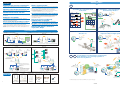
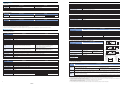
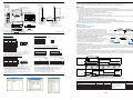
KR20 WIRELESS UNIT (AKR2)
■ To prevent from interference with the other wireless station (Japan only)
In the frequency band using this unit, in-plant radio station (license is necessary.) using at industrial such as microwave oven, science, medical
machinery and a production line in factory to identify mobile object, specified low power radio station (license is not necessary.) and amateur
radio station (license is necessary.) are managed
1) Before using this unit, please confirm that in-plant radio station to identify mobile object, specified low power radio station and amateur
radio station are not managed.
2) When some cases of harmful electric wave interference occurred from this unit to an in-plant radio station to identify mobile object, change
the using frequency immediately or stop discharging the electric wave. After that please contact us to consult measures to avoid
interference (for example, setting of partition).
3) When any other troubles such as harmful electric wave interference occurred from this unit to a specified low power radio station or an
amateur radio station or an amateur radio station, please contact us.
KR20
WIRELESS UNIT
■ Actual indication
(1)
(2)
(3)
2.4 DS 4
(4)
(1) 2.4:
(2) DS:
(3) 4:
(4) Bar:
2.4GHz band electric wave is used.
Modulation method is direct sequence type.
Intended interference distance is 40m.
All bands are used and possible to avoid the band of machine to identify mobile object.
High-speed, wireless communication
with easy installation and simple wiring!!
*Please put the attached label “Caution for using wireless unit” near the setting place.
■ Countries where the use of KR20 has been authorized
Products with the
indication label affixed to their rear side
As of May 2008, the use of KR20 has been authorized in the following countries.
Japan, China, 25 European countries (Austria, Belgium, Czech Republic, Denmark, Estonia, Finland, France*, Germany, Greece, Hungary,
Iceland, Ireland, Italy, Lithuania, Malta, Norway, Poland, Portugal, Slovakia, Slovenia, Spain, Sweden, Switzerland, UK, Netherlands)
* In France, this product must not be used outdoors. Please use it indoors only.
■ Compliance for EN standard
Obtained the European wireless certification (EN300 328)
In order to comply with EN standard, use this product in following condition.
• When installing this product to wall, install it on a DIN rail.
• Use power supply cord that is less than 3m.
• For communication cable (RS232C or RS485), use shielded cable, and connect one end of shield wire to ground. And use ferrite core
(correspond to TDK: ZCAT2035-0930) in the communication cable (RS232C or RS485) of wireless unit side. (Turn numbers: 2T)
Antenna with cable
*Antenna sold separately.
Antenna extension cable
High-speed
data transfer
250 m
range
(2.4 GHz, SS wireless)
Please contact ..........
Matsushita Electric Works, Ltd.
Antenna
with cable
available
Automation Controls Business Unit
Head Office: 1048, Kadoma, Kadoma-shi, Osaka 571-8686, Japan
Telephone: +81-6-6908-1050
Facsimile: +81-6-6908-5781
http://www.mew.co.jp/ac/e/
KR20 WIRELESS UNIT
ARCT1B301E ’08.5
All Rights Reserved © 2008 COPYRIGHT Matsushita Electric Works, Ltd.
ARCT1B301E 200805-3YT
Specifications are subject to change without notice.
RS485 type
and I/O type
New
Printed in Japan.
Matsushita Electric Works, Ltd.
http://www.mew.co.jp/ac/e/
03/2009
Application Examples
FEATURES
Optimum for high-speed data communications.
Wireless repeater function
134 kbps wireless communication speed optimum for high-speed data
communications.
Optimum for reducing the wiring and installation work.
The communicable distance between the master and a slave is approximately
250 m*1 outdoors*2 or approximately 50 m indoors. The communication
distance can be extended using the repeater function incorporated in this unit.
(Up to eight repeaters can be installed between the master and slave.)
Reduces the cable installation costs when the layout for machines and
equipments are changed or in places where the wiring is difficult.
*1 Linear distance in an open location
*2 The main unit, standard antenna and antenna with cable are designed for indoor use. If they are
used outdoors, then take waterproof measures such as using plastic cases, etc.
Common units for master and slave
Up to 254 terminal equipments can be connected.
The master and slave can be identified with the unit number settings on the
unit. When purchasing, you don’t have to worry about the master and slave
identifications.
The RS485 types allow up to 99 slave units to be connected for one master
and in RS485 mode, up to 31 terminal equipments can be connected for one
slave. Up to 254 terminal equipments can be connected in an entire network.
The I/O types allow up to 99 slave units or terminal equipments to be
connected for one master.
RS485 types are available.
The RS485 types do not need RS232C-RS485 converters, which were
conventionally required for communication with the RS485 communication
equipments and allow direct connections.
Plant
Sales office
Master
KR20
PLC
KR20
Component (2)
KR20
RS232C
Shop or office
Out of stock
Sensor input
Production control office
I/O output
KR20
Stockout
Slave
Out of stock
Sensor input
(1)
(2)
(3)
(4)
(5)
(6)
(7)
(8)
Slave
Slave
Component (4)
All models can be configured for 1:N topology.
KR20
Stockout
Sensor input
Indication of stockout appears
Line A
When MEWTOCOL is used for 1:N topology, all RS485 and I/O types can be mixed.
Compliant with wireless standards of
Japan, China, Europe
To transfer the data such as
2D code, etc.
Data can be exchanged between the master and slave over a distance of 250 m.
I/O type
Line B
Component Component Component Component
(5)
(6)
(7)
(8)
System Configurations
● Example of 1:1 topology
Site
To transmit the component pickup work
instructions by wireless.
Sensor input
Component (3)
The I/O types allow concurrent I/O and serial (RS232C) communications.
For 1:1 topology (one each master and slave), communication is possible
through settings on the main unit. For 1:N topology (one master and more
than one slave), the setting tool software (Control Configurator KR) is
available, which facilitates the settings. This software incorporates various test
functions helpful for unit installation. This software is downloadable from our
website.
KR20
Component (1)
24 dia. mushroom 24 dia. mushroom 24 dia. mushroom
button type
button type
button type
Concurrent I/O and serial (RS232C)
communications are possible.
Easy-to-operate main unit and setting tool software
To monitor the component stock
in the shelf
RS485 type
Counts the production number or
inspection data at a high speed
Display plate
PC
Master
KR20 Master
KR20
Slave
SW
RS
232C
Master
RS
232C
Slave
KR20
Drive circuit
RS
232C
Two components
are defective.
Site
KR20
Office
Office
*1 DC power supply
RS
232C
Voltage input
Message Runner
Two-way communication is possible between the master and slave.
KR20 Master
KR20 Slave
Slave
PLC
The production
quantity reached
1,000!
Two-way communication is possible between the master and slave.
Slave
*1 For switch inputting, a separate DC power supply is necessary for inputting.
● Example of 1:N topology
Slave
I/O type
RS485 type
The inspection
has completed.
Site
Up to 31 units
KR20
Slave No.1
SW
SW
DC power supply
*1
KR20
Slave No.2
DC power supply
*1
Voltage input
SW
KR20
Slave No.3
RS
485
DC power supply
*1
Voltage input
RS
485
KT4H Temperature controller
RS
485
Voltage input
Response
[%01$RC021CR]
Contact area read response
from slave No.1
RS
485
Building
KR20
Slave
KW4M
Eco-POWER METER
Shop
To transmit the measured power or temperature
of the machines or food storage systems or
their errors by wireless.
KR20
Slave
(Error input)
(I/O type)
KR20
Master
KR20
Master No.0
KR20
Slave
RS
232C
RS
232C
Data [%01#RCSX00001DCR]
(Contact area read command to
slave No.1)
Sending
RS
232C
RS
232C
OR
OR
MEWTOCOL
OR
PC
PLC
Up to eight input points, the “1:N
topology” function is available
requiring no PLCs. For details,
refer to the user’s manual.
*1 For switch inputting, a separate DC power supply is necessary for inputting.
PRODUCT TYPES
RS485 type
PC
PLC
RS
232C
WEB
LAN
Standard antenna
Lights
Air
conditioner
et
Supermark
KR20
Slave
(RS485 type)
Showcases
Web Datalogger Unit
KW4M
Eco-POWER METER
*2 Contact us for equipments that can be connected to the master and slave.
I/O type
KR20
Master
(RS485 type)
Antenna with cable Antenna extension cable Power supply cable for FPΣ
Office
KR20 Slave
(RS485 type)
KR20
Master
(I/O type)*
KW4M
KT4H
Temperature controller Eco-POWER METER
* The RS485 and I/O types can be mixed only when MEWTOCOL is used for 1: N topology.
2
AKR2002
(RS232C, RS485)
AKR2015 (I/O=8/8 (NPN), RS232C)
AKR2045 (I/O=6/6 (PNP), RS232C)
AKR2802
03/2009
AKR2803
AKR2804
AFPG805
3
Application Examples
FEATURES
Optimum for high-speed data communications.
Wireless repeater function
134 kbps wireless communication speed optimum for high-speed data
communications.
Optimum for reducing the wiring and installation work.
The communicable distance between the master and a slave is approximately
250 m*1 outdoors*2 or approximately 50 m indoors. The communication
distance can be extended using the repeater function incorporated in this unit.
(Up to eight repeaters can be installed between the master and slave.)
Reduces the cable installation costs when the layout for machines and
equipments are changed or in places where the wiring is difficult.
*1 Linear distance in an open location
*2 The main unit, standard antenna and antenna with cable are designed for indoor use. If they are
used outdoors, then take waterproof measures such as using plastic cases, etc.
Common units for master and slave
Up to 254 terminal equipments can be connected.
The master and slave can be identified with the unit number settings on the
unit. When purchasing, you don’t have to worry about the master and slave
identifications.
The RS485 types allow up to 99 slave units to be connected for one master
and in RS485 mode, up to 31 terminal equipments can be connected for one
slave. Up to 254 terminal equipments can be connected in an entire network.
The I/O types allow up to 99 slave units or terminal equipments to be
connected for one master.
RS485 types are available.
The RS485 types do not need RS232C-RS485 converters, which were
conventionally required for communication with the RS485 communication
equipments and allow direct connections.
Easy-to-operate main unit and setting tool software
For 1:1 topology (one each master and slave), communication is possible
through settings on the main unit. For 1:N topology (one master and more
than one slave), the setting tool software (Control Configurator KR) is
available, which facilitates the settings. This software incorporates various test
functions helpful for unit installation. This software is downloadable from our
website.
Plant
To monitor the component stock
in the shelf
Site
Sales office
Sensor input
PLC
KR20
Component (2)
Shop or office
Production control office
I/O output
KR20
Component (3)
Stockout
The I/O types allow concurrent I/O and serial (RS232C) communications.
KR20
RS232C
Out of stock
Sensor input
24 dia. mushroom 24 dia. mushroom 24 dia. mushroom
button type
button type
button type
Concurrent I/O and serial (RS232C)
communications are possible.
Master
KR20
Slave
Out of stock
Sensor input
(1)
(2)
(3)
(4)
(5)
(6)
(7)
(8)
Slave
Slave
Component (4)
All models can be configured for 1:N topology.
KR20
Stockout
Sensor input
Indication of stockout appears
Line A
When MEWTOCOL is used for 1:N topology, all RS485 and I/O types can be mixed.
Compliant with wireless standards of
Japan, China, Europe
To transfer the data such as
2D code, etc.
Data can be exchanged between the master and slave over a distance of 250 m.
I/O type
Line B
Component Component Component Component
(5)
(6)
(7)
(8)
System Configurations
● Example of 1:1 topology
KR20
Component (1)
To transmit the component pickup work
instructions by wireless.
RS485 type
Counts the production number or
inspection data at a high speed
Display plate
PC
Master
KR20 Master
KR20
Slave
SW
RS
232C
Master
RS
232C
Slave
KR20
Drive circuit
RS
232C
Two components
are defective.
Site
KR20
Office
Office
*1 DC power supply
RS
232C
Voltage input
Message Runner
Two-way communication is possible between the master and slave.
KR20 Master
KR20 Slave
Slave
PLC
The production
quantity reached
1,000!
Two-way communication is possible between the master and slave.
Slave
*1 For switch inputting, a separate DC power supply is necessary for inputting.
● Example of 1:N topology
Slave
I/O type
RS485 type
The inspection
has completed.
Site
Up to 31 units
KR20
Slave No.1
SW
SW
DC power supply
*1
KR20
Slave No.2
DC power supply
*1
Voltage input
SW
KR20
Slave No.3
RS
485
DC power supply
*1
Voltage input
RS
485
KT4H Temperature controller
RS
485
Voltage input
Response
[%01$RC021CR]
Contact area read response
from slave No.1
RS
485
Building
KR20
Slave
KW4M
Eco-POWER METER
Shop
To transmit the measured power or temperature
of the machines or food storage systems or
their errors by wireless.
KR20
Slave
(Error input)
(I/O type)
KR20
Master
KR20
Master No.0
KR20
Slave
RS
232C
RS
232C
Data [%01#RCSX00001DCR]
(Contact area read command to
slave No.1)
Sending
RS
232C
RS
232C
OR
OR
MEWTOCOL
OR
PC
PLC
Up to eight input points, the “1:N
topology” function is available
requiring no PLCs. For details,
refer to the user’s manual.
*1 For switch inputting, a separate DC power supply is necessary for inputting.
PRODUCT TYPES
RS485 type
PC
PLC
RS
232C
WEB
LAN
Standard antenna
et
Supermark
KR20
Slave
(RS485 type)
Lights
Air
conditioner
Showcases
Web Datalogger Unit
KW4M
Eco-POWER METER
*2 Contact us for equipments that can be connected to the master and slave.
I/O type
KR20
Master
(RS485 type)
Antenna with cable Antenna extension cable Power supply cable for FPΣ
Office
KR20 Slave
(RS485 type)
KR20
Master
(I/O type)*
KW4M
KT4H
Temperature controller Eco-POWER METER
* The RS485 and I/O types can be mixed only when MEWTOCOL is used for 1: N topology.
2
AKR2002
(RS232C, RS485)
AKR2015 (I/O=8/8 (NPN), RS232C)
AKR2045 (I/O=6/6 (PNP), RS232C)
AKR2802
AKR2803
AKR2804
AFPG805
3
03/2009
■ Product Types
3. Serial communication specifications (RS232C) *4
Item
1. Main unit
Model number
Product name
Remarks
Specifications
Interface
Conforming to RS232C
AKR2002
KR20 WIRELESS UNIT RS485 type
RS232C, RS485
Transmission distance
15m
AKR2015
KR20 WIRELESS UNIT I/O type (NPN)
I/O: 8/8 (NPN), RS232C
Transmission speed
1200, 2400, 4800, 9600, 19200, 38400, 57600, 115200 bit/s (Selectable with MODE switch)
AKR2045
KR20 WIRELESS UNIT I/O type (PNP)
I/O: 6/6 (PNP), RS232C
Communication method
Half-duplex
Synchronous system
Synchronous communication method
Transmission format
Stop bit: 1 bit, Parity: Not available/Available (odd/even), Data length: 7bit/8bit
Data buffer
2048 bytes (Max. data byte size for send and receive one time)
• A power supply cable (1 m) for the main unit is supplied with this product.
• Antenna is not attached. Select from optional supplies.
2. Setting software
—
Product name
Remarks
Setting tool for KR wireless unit
Downloadable from the website: http://www.mew.co.jp/ac/e/.
Use the tool Ver. 1.20 or later for KR20.
Control Configurator KR
3. Options
Model number
Product name
Remarks
4. Serial communication specifications (RS485) (only AKR2002) *4
Item
Specifications
Interface
Conforming to RS485
Transmission distance
1200m
Transmission speed
1200, 2400, 4800, 9600, 19200, 38400, 57600, 115200 bit/s (Selectable with MODE switch)
Communication method
Half-duplex
AKR2802
Standard antenna
2 pieces
Synchronous system
Synchronous communication method
AKR2803
Antenna with cable
2 pieces, 2 m length
Transmission format
Stop bit: 1 bit, Parity: Not available/Available (odd/even), Data length: 7bit/8bit
AKR2804
Antenna extension cable
Special order, 2 pieces, 2 m length
Data buffer
2048 bytes (Max. data byte size for send and receive one time)
AFPG805
Power supply cable for FPΣ
1 piece, 1 m length
Ending resistance
Approx. 120Ω (built-in) (Terminal “E” and terminal “–” are shorted when ending.)
Number of connected units
Max. 31
• Two antennas and two antenna extension cables are required per main unit.
• A magnet and double-sided tape are supplied with antennas with cable for fitting.
• When an antenna extension cable is used, the communication distance becomes short.
∗The user’s manual is downloadable from the website: http://www.mew.co.jp/ac/e/. Customer registration is required to download the manual.
1. General specifications
Specifications
RS485 type
I/O type
Rated voltage
12 to 24V DC
Operating voltage range
10.8 to 26.4V DC
Current consumption
150mA or less (During sending)
Inrush current
23A (when 24V DC)
Ambient temperature
–10 to +50°C
Storage temperature
–20 to +70°C
Ambient humidity
30 to 85%RH (at 25°C non-condensing)
Storage humidity
30 to 85%RH (at 25°C non-condensing)
Breakdown voltage
(initial)
500V AC for 1 min.
(Between power terminal and FG/DSUB connector)
500V AC for 1 min.
(Between power terminal and FG/DSUB connector,
Between power terminal and input/output terminal,
Between input terminal and output terminal)
100MΩ or more (at 500V DC mega)
(Between power terminal and FG/DSUB connector)
100MΩ or more (at 500V DC)
(Between power terminal and FG/DSUB connector,
Between power terminal and input/output terminal,
Between input terminal and output terminal)
Rated input voltage
12 to 24 V DC (voltage input)
Operating voltage range
10.8 to 26.4 V DC
Rated input current
AKR2045 (Output PNP type)
Approx. 3mA/when 12 V, Approx. 6mA/when 24 V
8 points/common (Either positive or negative of input
power supply can be connected.)
5
Input impedance
Approx. 4kΩ
Operation indicator
LED display (green)
AKR2015 (Output NPN type)
Insulation method
Optical coupler
Output type
Open collector (NPN)
Rated load voltage
12 to 24 V DC
Allowable load voltage range
10.8 to 26.4 V DC
1000V [p-p] with pulse width 50ns, 1 µs (based on in-house measurements) (Power terminal)
Overcurrent protection of
power supply
Fuse (Rated current: 3.15A)
Weight
Approx. 160g
Points per common*5
Off state leakage current
1 µA or less
On state voltage drop
2. Wireless specifications
7 point/common
(Signal output,
Communication error output)
RS485 type
1.5 V DC or less
Approx. 250 m outdoors* (straight, obstacle-free distance), Approx. 50 m indoors
Wave output
6mW/MHz or less
Frequency
2403.328MHz to 2480.128MHz
Number of channels
76ch (Select with communication channel switch)*1
15 channels recommended (when select fixed channel)*
Transmission speed
134kbps
Communication style
1: N topology (N: 99 units max.)
Repeater function
8 repeaters (Between master and slave)
—
Max. 60mA
AKR2015
LED display
ON ➝ OFF
Max. 80ms*3
LED
display
6
4
40 50
Ambient temperature (°C)
Specifications
RS485 type
• Operating mode change (SET, RUN, TEST)
• Communication channel change (CH switch)
• Unit No. change (UNIT No. switch)
I/O type
• Serial communication setup (MODE switch)
• Slave registration
• Initializing (Factory setting)
Data holding (When communication error)
Communication test: 3-stage LED display (With setting tool, it can do various communication tests such as changing data amount,
including repeaters and so on. And it can measure an approximate communication time.)
Field intensity monitor: 3-stage LED display (With setting tool, it can display and record a field intensity of each channel by numeric value.)
• Distinguish master or slave (MASTER)
• On communication, Power on (COM.)
• On setting, Complete setting (SET)
—
* The main unit, standard antenna and antenna with cable are designed for indoor use.
If they are used outdoors, then take water-proof measures such as using plastic cases, etc.
AKR2045
8
4
40 50
Ambient temperature (°C)
—
OFF ➝ ON
—
–
Current
Operation indicator
Test
function
Load
Input number and output number should be in the range of the blow according
to the ambient temperature.
Zener diode
Setting
function
2
12 to 24V DC
Output
10.8 to 26.4V DC
Surge absorber
Item
+
—
7. Functions specifications
Transmission distance
12 to 24V DC
COM (0V)
Voltage
I/O type
Direct sequence spread spectrum (DS-SS)
Load
Restriction of input number and output number of
simultaneously ON
Specifications
Wave type
Output
Output circuit diagram AKR2045 (PNP)
1.5A
9 points/common
(Signal output,
Communication error output)
External power supply
(+, – terminal)
Output circuit diagram AKR2015 (NPN)
0.3A
Max. inrush current
2
98m/s or more, 4 times on 3 axes
Open collector (PNP)
12 to 24V DC
COM
Internal circuit
Max. load current
AKR2045 (Output PNP type)
Internal circuit
Item
Internal circuit
Input
10 to 55Hz 1cycle/min. Double amplitude of 0.75mm, 10min. on 3 axes
Item
6 points/common (Either positive or negative of input
power supply can be connected.)
Input circuit diagram
Specifications
Noise immunity
Response time
Optical coupler
6. Output specifications (only AKR2015 and AKR2045)
Shock resistance
Number of channels in
same transmission area
Insulation method
Points per common*
200mA or less (During sending)
AKR2015 (Output NPN type)
No. of points per
common which are
simultaneously on
Item
Vibration resistance
Specifications
Item
■ Specifications
Insulation resistance
(initial)
5. Input specifications (only AKR2015 and AKR2045)
No. of points per
common which are
simultaneously on
Model number
• Error, Alarm, Caution (ALARM)
• Level indication (1, 2, 3: when using test function)
I/O operating display (16 or 12 points + 1 point of communication error)
*1 Adding to the fixed channel, 76ch (00 to 4B), 89 group channel can be selected.
Group channel is the function that it selects connectable channel from several fixed channels automatically. When using repeater function, use with the fixed channel.
When using group channel, settable channel numbers are decreased in the same communication area and the communication time becomes longer.
*2 It is different according to the mounting conditions, when several channels are used in the same communication area, communication error might occur due to interference radio wave.
*3 There are no error without serial communication at 1:1 topology.
Response time: Time from input signal to input terminal to output from output terminal in connected equipment
When input signal is shorter than response time, there is a possibility not to transfer to output side.
*4 RS232C and RS485 are not used in the same time.
*5 In case simultaneously ON of input and output, input number and output number are restricted according to the ambient temperature.
4
03/2009
5
■ Product Types
3. Serial communication specifications (RS232C) *4
Item
1. Main unit
Model number
Product name
Remarks
Conforming to RS232C
AKR2002
KR20 WIRELESS UNIT RS485 type
RS232C, RS485
Transmission distance
15m
AKR2015
KR20 WIRELESS UNIT I/O type (NPN)
I/O: 8/8 (NPN), RS232C
Transmission speed
1200, 2400, 4800, 9600, 19200, 38400, 57600, 115200 bit/s (Selectable with MODE switch)
AKR2045
KR20 WIRELESS UNIT I/O type (PNP)
I/O: 6/6 (PNP), RS232C
Communication method
Half-duplex
Synchronous system
Synchronous communication method
Transmission format
Stop bit: 1 bit, Parity: Not available/Available (odd/even), Data length: 7bit/8bit
Data buffer
2048 bytes (Max. data byte size for send and receive one time)
• A power supply cable (1 m) for the main unit is supplied with this product.
• Antenna is not attached. Select from optional supplies.
2. Setting software
—
Product name
Remarks
Setting tool for KR wireless unit
Downloadable from the website: http://www.mew.co.jp/ac/e/.
Use the tool Ver. 1.20 or later for KR20.
Control Configurator KR
3. Options
Model number
Product name
Remarks
4. Serial communication specifications (RS485) (only AKR2002) *4
Item
Specifications
Interface
Conforming to RS485
Transmission distance
1200m
Transmission speed
1200, 2400, 4800, 9600, 19200, 38400, 57600, 115200 bit/s (Selectable with MODE switch)
Communication method
Half-duplex
AKR2802
Standard antenna
2 pieces
Synchronous system
Synchronous communication method
AKR2803
Antenna with cable
2 pieces, 2 m length
Transmission format
Stop bit: 1 bit, Parity: Not available/Available (odd/even), Data length: 7bit/8bit
AKR2804
Antenna extension cable
Special order, 2 pieces, 2 m length
Data buffer
2048 bytes (Max. data byte size for send and receive one time)
AFPG805
Power supply cable for FPΣ
1 piece, 1 m length
Ending resistance
Approx. 120Ω (built-in) (Terminal “E” and terminal “–” are shorted when ending.)
Number of connected units
Max. 31
• Two antennas and two antenna extension cables are required per main unit.
• A magnet and double-sided tape are supplied with antennas with cable for fitting.
• When an antenna extension cable is used, the communication distance becomes short.
∗The user’s manual is downloadable from the website: http://www.mew.co.jp/ac/e/. Customer registration is required to download the manual.
1. General specifications
Specifications
RS485 type
I/O type
Rated voltage
12 to 24V DC
Operating voltage range
10.8 to 26.4V DC
Current consumption
150mA or less (During sending)
Inrush current
23A (when 24V DC)
Ambient temperature
–10 to +50°C
Storage temperature
–20 to +70°C
Ambient humidity
30 to 85%RH (at 25°C non-condensing)
Storage humidity
30 to 85%RH (at 25°C non-condensing)
Breakdown voltage
(initial)
500V AC for 1 min.
(Between power terminal and FG/DSUB connector)
500V AC for 1 min.
(Between power terminal and FG/DSUB connector,
Between power terminal and input/output terminal,
Between input terminal and output terminal)
100MΩ or more (at 500V DC mega)
(Between power terminal and FG/DSUB connector)
100MΩ or more (at 500V DC)
(Between power terminal and FG/DSUB connector,
Between power terminal and input/output terminal,
Between input terminal and output terminal)
Rated input voltage
12 to 24 V DC (voltage input)
Operating voltage range
10.8 to 26.4 V DC
Rated input current
AKR2045 (Output PNP type)
Approx. 3mA/when 12 V, Approx. 6mA/when 24 V
8 points/common (Either positive or negative of input
power supply can be connected.)
5
Input impedance
Approx. 4kΩ
Operation indicator
LED display (green)
AKR2015 (Output NPN type)
Insulation method
Optical coupler
Output type
Open collector (NPN)
Rated load voltage
12 to 24 V DC
Allowable load voltage range
10.8 to 26.4 V DC
1000V [p-p] with pulse width 50ns, 1 µs (based on in-house measurements) (Power terminal)
Overcurrent protection of
power supply
Fuse (Rated current: 3.15A)
Weight
Approx. 160g
Points per common*5
Off state leakage current
1 µA or less
On state voltage drop
2. Wireless specifications
7 point/common
(Signal output,
Communication error output)
RS485 type
1.5 V DC or less
Approx. 250 m outdoors* (straight, obstacle-free distance), Approx. 50 m indoors
Wave output
6mW/MHz or less
Frequency
2403.328MHz to 2480.128MHz
Number of channels
76ch (Select with communication channel switch)*1
15 channels recommended (when select fixed channel)*
Transmission speed
134kbps
Communication style
1: N topology (N: 99 units max.)
Repeater function
8 repeaters (Between master and slave)
—
—
Max. 60mA
AKR2015
LED display
* The main unit, standard antenna and antenna with cable are designed for indoor use.
If they are used outdoors, then take water-proof measures such as using plastic cases, etc.
ON ➝ OFF
Max. 80ms*3
LED
display
AKR2045
8
4
40 50
Ambient temperature (°C)
6
4
40 50
Ambient temperature (°C)
Specifications
RS485 type
I/O type
• Operating mode change (SET, RUN, TEST)
• Communication channel change (CH switch)
• Unit No. change (UNIT No. switch)
• Serial communication setup (MODE switch)
• Slave registration
• Initializing (Factory setting)
—
OFF ➝ ON
–
Current
Operation indicator
Test
function
Load
Input number and output number should be in the range of the blow according
to the ambient temperature.
Zener diode
Setting
function
2
12 to 24V DC
Output
10.8 to 26.4V DC
Surge absorber
Item
+
—
7. Functions specifications
Transmission distance
12 to 24V DC
COM (0V)
Voltage
I/O type
Direct sequence spread spectrum (DS-SS)
Load
Restriction of input number and output number of
simultaneously ON
Specifications
Wave type
Output
Output circuit diagram AKR2045 (PNP)
1.5A
9 points/common
(Signal output,
Communication error output)
External power supply
(+, – terminal)
Output circuit diagram AKR2015 (NPN)
0.3A
Max. inrush current
2
98m/s or more, 4 times on 3 axes
Open collector (PNP)
12 to 24V DC
COM
Internal circuit
Max. load current
AKR2045 (Output PNP type)
Internal circuit
Item
Internal circuit
Input
10 to 55Hz 1cycle/min. Double amplitude of 0.75mm, 10min. on 3 axes
Item
6 points/common (Either positive or negative of input
power supply can be connected.)
Input circuit diagram
Specifications
Noise immunity
Response time
Optical coupler
6. Output specifications (only AKR2015 and AKR2045)
Shock resistance
Number of channels in
same transmission area
Insulation method
Points per common*
200mA or less (During sending)
AKR2015 (Output NPN type)
No. of points per
common which are
simultaneously on
Item
Vibration resistance
Specifications
Item
■ Specifications
Insulation resistance
(initial)
5. Input specifications (only AKR2015 and AKR2045)
No. of points per
common which are
simultaneously on
Model number
4
Specifications
Interface
Data holding (When communication error)
Communication test: 3-stage LED display (With setting tool, it can do various communication tests such as changing data amount,
including repeaters and so on. And it can measure an approximate communication time.)
Field intensity monitor: 3-stage LED display (With setting tool, it can display and record a field intensity of each channel by numeric value.)
• Distinguish master or slave (MASTER)
• On communication, Power on (COM.)
• On setting, Complete setting (SET)
• Error, Alarm, Caution (ALARM)
• Level indication (1, 2, 3: when using test function)
—
I/O operating display (16 or 12 points + 1 point of communication error)
*1 Adding to the fixed channel, 76ch (00 to 4B), 89 group channel can be selected.
Group channel is the function that it selects connectable channel from several fixed channels automatically. When using repeater function, use with the fixed channel.
When using group channel, settable channel numbers are decreased in the same communication area and the communication time becomes longer.
*2 It is different according to the mounting conditions, when several channels are used in the same communication area, communication error might occur due to interference radio wave.
*3 There are no error without serial communication at 1:1 topology.
Response time: Time from input signal to input terminal to output from output terminal in connected equipment
When input signal is shorter than response time, there is a possibility not to transfer to output side.
*4 RS232C and RS485 are not used in the same time.
*5 In case simultaneously ON of input and output, input number and output number are restricted according to the ambient temperature.
03/2009
5
■ Part Name and Dimensions (Unit: mm)
■ Caution for use
Main unit
1) When mounting, (wiring, adjustment etc.), be careful not to add static electricity to connector, switch and antenna.
2) Do not squeeze the switches or push buttons with an excessive force. Otherwise, they may be damaged.
Antenna
With
standard
antenna
7.8 dia.
7 dia.
■ Mounting
Antenna mounting section
Communication channel switch
90°
90°
Range of
movement
10 dia.
MODE switch
ENTER switch
Four LED displays DIN hook
(4.5)
3.5
Cover
25
DIN rail attachment
gap (35 mm width)
2-4.5 dia.
AKR2002
Power supply connector
RS232C
AKR2015
AKR2045
Range of
movement
35 dia.
SMA plug
Unit No. switch
Standard antenna
(AKR2802)
AKR2002
Power supply connector RS232C
+100
0
28.6
2000
85
71
40
20.4
Operating mode switch
110±0.5
110.5±2.5
120
103
31
104.4
(5.85)
(106)
1) Do not place the units in the vicinity of radios or TVs. Otherwise, the reception may be impaired.
2) If nearby broadcasting or wireless stations emit radio waves with a high field intensity, then this wireless system may not be used.
3) This system uses frequencies on 2.4 GHz band for data communication. If there are other devices using the same frequency band in its
vicinity, then the communication may be impaired due to interference.
4) In order to make the wireless performance better, pay attention to the below items.
• Mount the unit as high as possible.
• Connect 2 of the antenna and the mounting direction is vertical for the ground.
• Antenna should be keep away from metal board. If antennas are mounted inside the control board, the wireless performance will
decrease.
• Keep away from the place or line that noise might occur.
• Mount in the place where electric wave condition is good refer to field intensity monitor.
• When using several channels in the same communication area, check if there is no influence each other.
5) When mounting the unit to DIN rail, hook the upper part and push DIN hook. When removing it, pull out with minus driver until locking DIN
hook. And fastening plate (ATA4806) is recommended to prevent from moving.
Antenna with cable
(AKR2803)
■ Restrictions
Accessories:
A magnet and a double-faced tape
RS485
● Wired communication restrictions
LED display
Output
terminal
block
Input terminal block
AKR2015
AKR2045
[With cover open]
General tolerance: ±1.0
■ Termainal Layouts
RS232C Connector
Power supply connector
• Interface specifications
DSUB 9-pin termainal layouts
Power supply connector 3-pin termainal layouts
1
–
2
GND
Blue
3
FG
Green
1
–
2
RD
Output
3
SD
Input
4
–
–
5
SG
Signal GND
6
–
–
7
(RS)
(Unused)
8
(CS)
(Unused)
9
–
No connection
Direction of communication between the master and slave
(1:1 topology with repeaters or 1:N topology)
Command and response is assumed in the communication procedure.
Set the master to a command sender and the slave to a response sender.
Otherwise, the communication is impossible. If both units are set to
command senders, then communication will not be possible.
Pin No. Signal name Line color
Pin No. Signal name Input/Output
9
6
5
12-24V DC Brown
3 2 1
I/O terminal block (only AKR2015 and AKR2045)
Terminal block 10, 12-pin termainal layouts
Input terminal block (AKR2015)
• Flow control is not supported now.
• Without flow control, use DSUB 9-pin female-female straight cable to
connect to the computer. If using male-female straight cable, use
attached gender changer in main unit. (when using setting tool etc.)
COM 0
1
2
Input
IN
3 COM 4
5
6
7
COM 0
1
RS485 terminal block (only AKR2002)
*The both COM of input are connected internally.
*The both COM of input are connected internally.
Output terminal block (AKR2015)
Output terminal block (AKR2045)
Polling time
Signal name Input/Output
1
+
RS485 (+)
2
−
RS485 (−)
3
+
RS485 (+)
4
−
RS485 (−)
5
E
1
2
3
4
5
COM 0
1
Output
OUT
2 3 COM 4
Output of
communication
error
5
6
7 COM ERR
+
–
0
Output
OUT
1 2 + –
Output of
communication
error
*The both COM of output and COM
of communication error are
connected internally.
Orange color
button
3
*The both + are connected internally.
The both - are connected internally.
4
5
Slave
Terminal
*1
Master input signal
ERR
Orange color
button
• Shielded cable (connectable range: AWG26-20,cross-section area:
0.14-0.5mm2) is recommended. Select the diameter that there is margin in
the current capacity. (stripped wire length is 9mm)
• When using shielded cable, the grounding connection should have a
resistance of less than 100Ω, and grounded one end.
• Connect the wire with pushing the orange color button.
Changes during wireless communication cannot be transmitted.
Wireless
communication
status
Wireless
communication
(forward path)
Wireless
communication
(backward path)
Wireless
communication
(forward path)
Wireless
communication
(backward path)
Wireless
communication
(forward path)
Wireless
communication
(backward path)
Master ➝ Slave
Slave ➝ Master
Master ➝ Slave
Slave ➝ Master
Master ➝ Slave
Slave ➝ Master
AKR2015
Slave output signal
Slave input signal
■ KR20 WIRELESS UNIT Utilities
Response time
● Settings tool
Routing function
Master
PC
Response
AKR2015
Master output signal
• 1 and 3, 2 and 4 are connected internally.
• Shielded twisted-pair cable (connectable range: AWG26-20, cross-section
area: 0.14-0.5mm2) is recommended. (stripped wire length is 9mm)
• When using shielded cable, the grounding connection should have a
resistance of less than 100Ω, and grounded one end.
• Connect between each unit by extending wiring in the transmission line.
Cannot use branch connection.
• At terminal unit, “E” terminal (No.5) should be shorted with “–” terminal
(No.4). (Terminator connection)
Response
During 1:1 topology or 1:1 topology with repeaters for the I/O type , the input or output signals are not always monitored. They are monitored
only immediately before wireless transmission and when their information is transmitted. In this case, if the input signal duration is shorter than
the polling time*1, then it may not be transmitted to the output terminal. Therefore, in order to ensure that the input signal is transmitted, it must
be held for the polling time or more.
5
Terminal block 5-pin termainal layouts
Pin No.
Command
● Input signal time
Input terminal block (AKR2045)
Input
IN
2 3 COM 4
Command
equipment
Command and response sequence
If commands are sent in succession, then define a sequence, in which a command is sent after the response to the previous command is
returned. If a time-out is defined, then the time required for wireless communication must be taken into consideration. The time required for
wireless communication may be extended depending on the communication environment. If the interval between two commands is fixed, then
a command and a response may collide with each other.
1
1, 4 and 6 are connected internally.
Separation of data sent on wire
Max. 2,048 bytes
Max. 2,048 bytes
The wireless unit detects the end of data sent on wire not by control
First data
Next data
codes such as “CR”, etc., but by the idle time. Initially, if there is an idle
RS232C
or
RS485
Separation
time on wire
time equivalent to 10 characters, then it will be deemed the end of data
(Initial value: 10 characters)
and the wireless unit will start communicating. Therefore, if consecutive
data includes an idle time equivalent to 10 characters or more, then the data will be separated. However, if the idle time between two
successive items of data is equivalent to 10 characters or less, then they will be deemed to be partial data and will not be sent correctly.
Communication test function
Field intensity monitor
*2
Response time
*1 The polling time refers to a cycle for the master to continuously transmit (polling) data to a slave.
*2 The response time refers to the time required for the signal inputted to the input terminal to be outputted from the output terminal of the partner unit.
● Protocol for 1:N topology
RS485 type
I/O type
MEWTOCOL (MEW)
Communication protocol
䡬
䡬
MODBUS ASCII
䡬
–
MODBUS RTU
䡬
–
GT Series Original
䡬
–
Message Runner Original
䡬
–
Restrictions
Remark
*1
• The volume of data to be
simultaneously transmitted must
not exceed 2,048 bytes.
• The time-out must be able to be
extended.
Screens cannot be transferred.
Screens cannot be transferred.
*1 Operations using the PLC software are not supported.
*2 Use with 1:1 topology or 1:1 topology with repeaters for other protocols.
6
7
03/2009
KR20 WIRELESS UNIT (AKR2)
■ To prevent from interference with the other wireless station (Japan only)
In the frequency band using this unit, in-plant radio station (license is necessary.) using at industrial such as microwave oven, science, medical
machinery and a production line in factory to identify mobile object, specified low power radio station (license is not necessary.) and amateur
radio station (license is necessary.) are managed
1) Before using this unit, please confirm that in-plant radio station to identify mobile object, specified low power radio station and amateur
radio station are not managed.
2) When some cases of harmful electric wave interference occurred from this unit to an in-plant radio station to identify mobile object, change
the using frequency immediately or stop discharging the electric wave. After that please contact us to consult measures to avoid
interference (for example, setting of partition).
3) When any other troubles such as harmful electric wave interference occurred from this unit to a specified low power radio station or an
amateur radio station or an amateur radio station, please contact us.
KR20
WIRELESS UNIT
■ Actual indication
(1)
(2)
(3)
2.4 DS 4
(4)
(1) 2.4:
(2) DS:
(3) 4:
(4) Bar:
2.4GHz band electric wave is used.
Modulation method is direct sequence type.
Intended interference distance is 40m.
All bands are used and possible to avoid the band of machine to identify mobile object.
High-speed, wireless communication
with easy installation and simple wiring!!
*Please put the attached label “Caution for using wireless unit” near the setting place.
■ Countries where the use of KR20 has been authorized
Products with the
indication label affixed to their rear side
As of May 2008, the use of KR20 has been authorized in the following countries.
Japan, China, 25 European countries (Austria, Belgium, Czech Republic, Denmark, Estonia, Finland, France*, Germany, Greece, Hungary,
Iceland, Ireland, Italy, Lithuania, Malta, Norway, Poland, Portugal, Slovakia, Slovenia, Spain, Sweden, Switzerland, UK, Netherlands)
* In France, this product must not be used outdoors. Please use it indoors only.
■ Compliance for EN standard
Obtained the European wireless certification (EN300 328)
In order to comply with EN standard, use this product in following condition.
• When installing this product to wall, install it on a DIN rail.
• Use power supply cord that is less than 3m.
• For communication cable (RS232C or RS485), use shielded cable, and connect one end of shield wire to ground. And use ferrite core
(correspond to TDK: ZCAT2035-0930) in the communication cable (RS232C or RS485) of wireless unit side. (Turn numbers: 2T)
Antenna with cable
*Antenna sold separately.
Antenna extension cable
High-speed
data transfer
(2.4 GHz, SS wireless)
Please contact ..........
Matsushita Electric Works, Ltd.
Antenna
with cable
available
Automation Controls Business Unit
Head Office: 1048, Kadoma, Kadoma-shi, Osaka 571-8686, Japan
Telephone: +81-6-6908-1050
Facsimile: +81-6-6908-5781
http://www.mew.co.jp/ac/e/
Specifications are subject to change without notice.
New
Printed in Japan.
http://www.mew.co.jp/ac/e/
03/2009
RS485 type
and I/O type
KR20 WIRELESS UNIT
ARCT1B301E ’08.5
All Rights Reserved © 2008 COPYRIGHT Matsushita Electric Works, Ltd.
ARCT1B301E 200805-3YT
250 m
range
Matsushita Electric Works, Ltd.