1
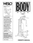
ORDERING REPLACEMENT PARTS
If you encounter any problems with this product or if your need to order replacement parts, contact the ICON
Health & Fitness, Ltd. office, or write:
ICON Health & Fitness, Ltd.
Unit 4
Revie Road Industrial Estate
Revie Road
Leeds
LS118JG
Model No. WLEMSY80000
Serial No.
USER'S MANUAL
Tel: Country Code: 0345-089009
0345-089009
Fax: 0113-2411120
To help us assist you, please be prepared to give the following information:
• The MODEL of the product (WLEMSY80000)
• The NAME of the product (WESLO® GYM 2000 weight system)
• The SERIAL NUMBER of the product (see the front cover of this manual)
• The KEY NUMBER and DESCRIPTION of the part(s) (see the PART LIST on page 18 of this manual).
Serial Number Decal
QUESTIONS?
As a manufacturer, we are
committed to providing
complete customer satisfaction.
If you have questions, or if
there are missing parts, we will
guarantee complete satisfaction
through our Customer Service
Department.
Please CALL:
0345-089009
Or WRITE:
ICON Health & Fitness, Ltd.
Unit 4
Revie Road Industrial Estate
Revie Road
Leeds
LS118JG
CAUTION
Read all precautions and instructions in this manual before using
this equipment. Save this manual
for future reference.
Part No. 172020 R0301A
Printed in Canada © 2001 ICON Health & Fitness, Inc.
Visit our website at
www.weslo.com
new products, prizes,
fitness tips, and much more!
EXPLODED DRAWING—Model No. WLEMSY80000
TABLE OF CONTENTS
IMPORTANT PRECAUTIONS . . . . . . . . . . . . . . . . . . . . . . . . . . . . . . . . . . . . . . . . . . . . . . . . . . . . . . . . . . . . . .3
BEFORE YOU BEGIN . . . . . . . . . . . . . . . . . . . . . . . . . . . . . . . . . . . . . . . . . . . . . . . . . . . . . . . . . . . . . . . . . . .4
ASSEMBLY . . . . . . . . . . . . . . . . . . . . . . . . . . . . . . . . . . . . . . . . . . . . . . . . . . . . . . . . . . . . . . . . . . . . . . . . . . .5
ADJUSTMENT . . . . . . . . . . . . . . . . . . . . . . . . . . . . . . . . . . . . . . . . . . . . . . . . . . . . . . . . . . . . . . . . . . . . . . . .14
TROUBLE-SHOOTING AND MAINTENANCE . . . . . . . . . . . . . . . . . . . . . . . . . . . . . . . . . . . . . . . . . . . . . . . . .16
CABLE DIAGRAM . . . . . . . . . . . . . . . . . . . . . . . . . . . . . . . . . . . . . . . . . . . . . . . . . . . . . . . . . . . . . . . . . . . . .17
PART LIST . . . . . . . . . . . . . . . . . . . . . . . . . . . . . . . . . . . . . . . . . . . . . . . . . . . . . . . . . . . . . . . . . . . . . . . . . . .18
EXPLODED DRAWING . . . . . . . . . . . . . . . . . . . . . . . . . . . . . . . . . . . . . . . . . . . . . . . . . . . . . . . . . . . . . . . . . .19
ORDERING REPLACEMENT PARTS . . . . . . . . . . . . . . . . . . . . . . . . . . . . . . . . . . . . . . . . . . . . . . . .Back Cover
Note: A PART IDENTIFICATION CHART is attached in the centre of this manual. Remove the PART IDENTIFICATION CHART before begining assembly.
8
11
11
17
7
67
8
76
59
6
68 77
8
71
65
60
27
12
59
8
2 66
66
70
3
58
18
8
78
12
3
63
12
3
75
72
11
6
86
54
8
48
55 9 62
47
3
49
49
33
51
44
51
48
57
8
3
8
62
47
2
82
9
55
8
3
46
44
46
3
24
64
21
44
54
61
44
53
2
11
74
49
90
21
53
56
12
73
3
77
61
21
15
49
90
6
15
9
78
52
15 3
21
9
2
77
12
69
15 6
27
R0301A
33
45
8
44
77
91
17
48
45
23
3
41
81
8
85
84
43 10
11
3
3
8
11
80
8
48
24
3
83
89
42
3
79
13
39
88
40
25
34
15 16
87
3
26
5
8
9
22
3
21
6 20
19
38
37
18
3
23
8
14
88
3
4
12
11
15
8
3
10
7
7
27
WESLO is a registered trademark of ICON Health & Fitness, Inc.
2
19
33
30
34
29
35
50
8
59
31
3
34
1
30
28
34
14
32
36
50
32
PART LIST—Model No. WLEMSY80000
Key No. Qty.
1
2
3
4
5
6
7
8
9
10
11
12
13
14
15
16
17
18
19
20
21
22
23
24
25
26
27
28
29
30
31
32
33
34
35
36
37
38
39
40
41
42
43
44
45
46
2
5
24
1
1
6
6
21
5
4
10
8
1
3
6
1
1
8
2
1
6
1
1
2
8
1
3
1
1
2
1
2
3
4
1
1
2
2
1
1
1
1
2
6
2
2
Description
Key No. Qty.
5/16” x 2 1/2” Carriage Bolt
5/16” Jam Nut
5/16” Nylon Locknut
Base
Stabiliser
3/8” Jam Nut
1/4” Nylon Locknut
5/16” Flat Washer
3/8” Flat Washer
1/4” Flat Washer
5/16” x 2 3/4” Bolt
3/8” x 1 3/4” Bolt
Seat
5/16” x 2 3/4” Carriage Bolt
3 1/2” Pulley
3/8” X 3 1/2” Bolt
5/16” x 3” Bolt
1/4” x 3/4” Screw
Weight Bumper
Pulley Plate
3/8” Nylon Locknut
1” Metal Spacer
Short Cable
5/16” x 1 1/2” Bolt
Weight
5” Weight Pin
2” Inner Cap
13 1/2” Pad Tube
Leg Lever
6” Pad
13” Pad Tube
1 1/2” Inner Cap
5/16” x 2 1/4” Bolt
3/4” Round Inner Cap
5/16” x 2” Eyebolt
Seat Frame
Seat Plate
1/4” x 2” Carriage Bolt
Nylon Strap
Seat Knob
Backrest
Front Upright
1/4” x 2 1/2” Screw
1 3/4” Inner Cap
10” Pad
Arm
47
48
49
50
51
52
53
54
55
56
57
58
59
60
61
62
63
64
65
66
67
68
69
70
71
72
73
74
75
76
77
78
79
80
81
82
83
84
85
86
87
88
89
90
91
#
2
4
2
2
2
1
2
4
2
2
1
2
4
2
3
2
1
1
2
1
1
2
1
1
1
2
2
1
1
1
4
2
1
1
1
1
3
1
1
2
1
2
1
2
1
1
R0301A
Description
7” Handle
Handgrip
1” Round Inner Cap
5 3/4” Pad
1/2” x 3/8” Spacer
Arm Frame
Plastic Bushing
1” Retainer
1” Round Cover Cap
Large “U” Bracket
1 1/4” Inner Cap
Narrow Swivel Bracket
Cable Trap
4 1/2” “L” Pin
5/16” x 2” Bolt
3/8” x 2 1/2” Bolt
Stop Bracket
1” Plastic Stop
1/2” x 1/2” Spacer
Long Cable
Top Frame
Arm Frame Bushing
Arm Frame Cover
3/8” x 2 3/4” Bolt
Wide Swivel Bracket
Weight Guide
Weight Guide Spacer
5/16” x 6” Bolt
Adjustment “U” Bracket
5/16” x 3 1/4” Bolt
4 1/2” Pulley
“I” Plate
Weight Tube Bumper
Weight Tube
Weight Guide Bracket
Rear Upright
Cable Clip
Chain
Lat Bar
Brace
5/16” x 3 1/2” Bolt
2” Outer Cap
Slotted Flange Bushing
1” Inner Cap
5/16” x 3” Short Thread Bolt
User’s Manual
IMPORTANT PRECAUTIONS
WARNING:
To reduce the risk of serious injury, read the following important precautions
before using the weight system.
1. Read all instructions in this manual before
using the weight system. Use the weight
system only as described.
10. Never release the arms, leg lever, lat bar, or
nylon strap whilst weights are raised; the
weights will fall with great force.
2. It is the responsibility of the owner to ensure
that all users of the weight system are adequately informed of all precautions and
instructions.
11. Always disconnect the lat bar from the weight
system when performing an exercise that
does not use the lat bar.
12. If you feel pain or dizziness at any time whilst
exercising, stop immediately and begin cooling down.
3. The weight system is intended for home use
only. Do not use the weight system in any
commercial, rental, or institutional setting.
13. Keep children under 12 away from the weight
system at all times.
4. Use the weight system only on a level surface.
Cover the floor beneath the weight system to
protect the floor or carpet.
14. The decals shown at
the right (1) and
below (2) have been
attached to the
weight system in the
locations shown on
page 4. If a decal is
missing or illegible,
please call 0345089009 to order a
free replacement
decal.
5. Inspect and tighten all parts each time you use
the weight system. Replace any worn parts
immediately.
6. Always wear athletic shoes for foot protection
whilst exercising.
7. Keep hands and feet away from moving parts.
8. Always stand on the foot plate when performing an exercise that could cause the weight
system to tip.
9. Make sure that the cables remain on the pulleys at all times. If the cables bind as you are
exercising, stop immediately and make sure
that the cables are on all of the pulleys.
Keep hands and
fingers clear of
this area.
WARNING:
Before beginning this or any exercise program, consult your physician. This
is especially important for persons over the age of 35 or persons with pre-existing health problems.
Read all instructions before using. ICON assumes no responsibility for personal injury or property
damage sustained by or through the use of this product.
Note: “#” indicates a non-illustrated part. Specifications are subject to change without notice. See the back cover
of the user’s manual for information about ordering replacement parts.
18
3
BEFORE YOU BEGIN
CABLE DIAGRAM
Thank you for selecting the versatile WESLO® GYM
2000 weight system. The GYM 2000 offers an impressive array of weight stations designed to develop
every major muscle group of the body. Whether your
goal is to tone your body, build dramatic muscle size
and strength, or improve your cardiovascular system,
the GYM 2000 will help you to achieve the specific
results you want.
you have additional questions, please call our
Customer Service Department toll-free at 0345089009. To help us assist you, please note the product
model number and serial number before calling. The
model number is WLEMSY80000. The serial number
can be found on a decal attached to the weight system
(see the front cover of this manual).
The cable diagram below shows the proper routing of the Short Cable (23) and the Long Cable (66). Use the
diagram to make sure that the two cables are assembled correctly. The letters show the routing of the Short
Cable; the numbers show the routing of the Long Cable.
2
8—Top Framer
4
1
Before reading further, please look at the drawing
below and familiarise yourself with the parts that are
labelled.
For your safety and benefit, read this manual carefully before using the GYM 2000 weight system. If
Long Cable (66)
High Pulley Station
ASSEMBLED
DIMENSIONS:
Height: 192 cm
Width: 109 cm
Length: 150 cm
High Pulley Station
7
5
Lat Bar
6
3
Arms
Warning Decal 1
C
Backrest
Warning Decal 2
D—Weight Tube
B
Leg Lever
Weight Stack
A
Low Pulley Station
Weight Pin
Short Cable (23)
Low Pulley Station
Foot Plate
4
17
TROUBLE-SHOOTING AND MAINTENANCE
ASSEMBLY
Inspect and tighten all parts each time you use the weight system. Replace any worn parts immediately. The
weight system can be cleaned using a damp cloth and mild non-abrasive detergent. Do not use solvents.
Make sure you have the following tools:
Make Assembly Easier for Yourself.
TIGHTENING THE CABLES
Adjustment
Screw
15
Woven cable, the type of cable used on the weight
system, can stretch slightly when it is first used. If
there is slack in the cables before resistance is felt,
the cables should be tightened. Locate the adjustment
sleeve and adjustment screw near the lower end of
the Short Cable (23). Loosen the adjustment screw.
Pull the end of the Short Cable until there is no slack
in the cables. Slide the adjustment sleeve and the ball
against the indicated 3 1/2” Pulley (15). Retighten the
adjustment screw. Make sure that the cables are not
too tight, or the top weight will be lifted off the weight
stack.
23
Ball
15
Adjustment
Sleeve
• Two adjustable spanners
Everything in this manual is designed to
ensure that the weight system can be assembled successfully by anyone. Before beginning assembly, make sure to read the
information on this page; this brief introduction will save you much more time than
it takes to read it.
• One phillips screwdriver
• One rubber mallet
• You will also need grease or petroleum jelly, a
small amount of soapy water, and clear tape or
masking tape.
Note: Assembly will be more convenient if you have
a socket set, a set of open-end or closed-end spanners, or a set of ratchet spanners.
Assembly Requires Two Persons
For your convenience and safety, assemble the
weight system with the help of another person.
23
How to Unpack the Box
Set Aside Enough Time
Place all parts of the weight system in a cleared
area and remove the packing materials. Do not dispose of the packing materials until assembly is completed.
Due to the many features of the weight system, the
assembly process will require a few hours. By setting aside plenty of time and by deciding to make
the task enjoyable, assembly will go smoothly. You
may want to assemble the weight system over a
couple of evenings.
Tightening Parts
Tighten all parts as you assemble them, unless
instructed to do otherwise.
How to Orient Parts
As you assemble the weight system, make sure
that all parts are oriented exactly as shown in the
drawings.
Select a Location for the Weight System
Because of its weight and size, the weight system
should be assembled in the location where it will be
used. Make sure that there is enough room to walk
around the weight system as you assemble it.
How to Identify Parts
To help you identify the small parts used in assembly, we have included a PART IDENTIFICATION
CHART in the centre of this manual. Place the
chart on the floor and use it to easily identify parts
during each assembly step. Note: Some small
parts may have been pre-attached. If a part is
not in the parts bag, check to see if it has been
pre-attached.
Questions?
If you have questions after reading the assembly
instructions, please call our Customer Service
Department toll-free at 0345-089009.
1. Before you begin, make sure you have carefully
read the instructions at the top of this page.
1
20
Press a 2” Inner Cap (27) into the Base (4).
3
Attach the Pulley Plate (20) to the Base (4) with two
5/16” x 2 3/4” Bolts (11), two 5/16” Flat Washers (8),
and two 5/16” Nylon Locknuts (3).
4
11
Insert two 5/16” x 2 1/2” Carriage Bolts (1) up
through the Base (4).
8
1
27
16
5
2. Press the two 2” Outer Caps (88) onto the
Stabiliser (5).
ATTACHING THE LEG LEVER TO THE LOW
PULLEY STATION
2
Insert two 5/16” x 2 3/4” Carriage Bolts (14) up
through the Stabiliser (5). Slide the end of the Base
(4) onto the Carriage Bolts. Slide the Rear Upright
(82) onto the Carriage Bolts; make sure the sloped
bracket is oriented as shown. Thread two 5/16”
Nylon Locknuts (3) onto the Carriage Bolts. Do not
tighten the Nylon Locknuts yet.
To use the Leg Lever (29), the seat must be attached
to the Front Upright (42) (see ATTACHING AND
REMOVING THE SEAT on page 14). Attach the Chain
(84) between the Short Cable (23) and the 5/16” x 2”
Eyebolt (35) on the Leg Lever with two Cable Clips
(83).
Low Side
82
42
23
11
Attach the ends of the Braces (86) with slotted
holes to the Stabiliser (5) with two 5/16” x 2 3/4”
Bolts (11), two 5/16” Flat Washers (8), and two
5/16” Nylon Locknuts (3). Do not tighten the Nylon
Locknuts yet.
35
84
Slot
11
8
2
88
86
Attach the other ends of the Braces (86) to the
Rear Upright (82) with a 5/16” x 2 3/4” Bolt (11), a
5/16” Flat Washer (8), and a 5/16” Jam Nut (2).
Do not tighten the Jam Nut yet.
29
83
ATTACHING THE LAT BAR OR NYLON STRAP TO
THE HIGH PULLEY STATION
66
83
3
5
Slot
8
8
3
4
88
3
14
85
Attach the Lat Bar (85) to the Long Cable (66) with a
Cable Clip (83). For some exercises, the Chain (84)
should be attached between the Lat Bar and the Long
Cable with two Cable Clips. Adjust the length of the
Chain between the Lat Bar and the Long Cable so
the Lat Bar is in the correct starting position for
the exercise to be performed.
84
39
The Nylon Strap (39) can be attached in the same
manner.
3. Press the 1 1/4” Inner Cap (57) into the Front
Upright (42).
3
63
24
61
Attach the 1” Plastic Stop (64) to the centre hole in
the Stop Bracket (63) with a 5/16” x 1 1/2” Bolt (24)
and a 5/16” Jam Nut (2).
64
2
8
Attach the Stop Bracket (63) to the Front Upright
(42) with the 5/16” x 2” Bolt (61), a 5/16” Flat
Washer (8), and a 5/16” Nylon Locknut (3).
57
3
ATTACHING THE LAT BAR OR NYLON STRAP TO
THE LOW PULLEY STATION
39
23
Attach the Lat Bar (85) to the Short Cable (23) with a
Cable Clip (83). For some exercises, the Chain (84)
should be attached between the Lat Bar and the Short
Cable with two Cable Clips. Adjust the length of the
Chain between the Lat Bar and the Short Cable so
the Lat Bar is in the correct starting position for
the exercise to be performed.
83
84
85
42
Slide the Front Upright (42) onto the two 5/16” x
2 1/2” Carriage Bolts (1) in the Base (4). Attach the
Front Upright to the Base with two 5/16” Nylon
Locknuts (3). Do not tighten the Nylon Locknuts
yet.
The Nylon Strap (39) can be attached in the same
manner.
4
83
3
1
6
15
4. Press two 2” Inner Caps (27) into the Top Frame
(67).
ADJUSTMENT
The instructions below describe how each part of the weight system can be adjusted. IMPORTANT: When
attaching the lat bar or nylon strap, make sure that the attachments are in the correct starting position
for the exercise to be performed. If there is any slack in the cable or chain as an exercise is performed,
the effectiveness of the exercise will be reduced.
Attach the Top Frame (67) to the Rear Upright (82),
the Front Upright (42), and the Stop Bracket (63)
with 5/16” x 2 3/4” Bolts (11), 5/16” Flat Washers
(8), and 5/16” Nylon Locknuts (3) as shown. Do
not tighten the Nylon Locknuts yet.
CHANGING THE WEIGHT SETTING
Tighten all nuts used in steps 2–4.
To change the weight setting, insert the 5” Weight Pin
(26) under one of the Weights (25). Make sure to
insert the Weight Pin until the bent end of the Weight
Pin is touching the Weights, and to turn the bent end
downward. The weight setting can be changed from
12.5 pounds to 100 pounds, in increments of 12.5
pounds (one pound is equal to .454 kg). Note: Due
to the cables and pulleys, the actual amount of
resistance at each exercise station will vary from
the weight setting.
11
4
11
8
27
67
3
63
42
5
25
Stack seven Weights (25) on the Weight Bumpers
(19). Each Weight must be turned so the pin
groove is facing the Front Upright (42). The holes
in the Weights must be aligned with the holes in
the Weight Bumpers.
25
27
3
3
5. Set the two Weight Bumpers (19) on the indicated
plate on the Base (4). Align the holes in the Weight
Bumpers with the holes in the plate.
8
8
82
26
11
Pin Groove
19
42
CAUTION:
Be careful to avoid tipping the stack of Weights (25) until step 6 is
completed.
SWITCHING THE ARMS TO THE PRESS MODE OR
THE BUTTERFLY MODE
19
6
52
To perform the bench press exercise, switch the Arms
(46) to the press mode by inserting the two 4 1/2” “L”
Pins (60) into the indicated holes in the Arm Frame
(52) and the Arms.
60
Insert the Weight Tube (80) into the stack of
Weights (25). Slide the eighth Weight onto the
upper end of the Weight Tube. The Weight Tube
must be turned so the welded pin is in the pin
groove in the Weight.
46
72
Locate the lower ends of the Weight Guides (72);
there are holes near the upper ends. Insert the
lower ends of the Weight Guides into the eight
Weights (25).
ATTACHING AND REMOVING THE SEAT
40
Set the bracket on the Seat Frame (36) onto the pins
on the Front Upright (42). Secure the Seat Frame
with the 5/16” x 2 3/4” Carriage Bolt (14) and the Seat
Knob (40).
Upper Ends of
Weight Guides
have Holes
6. Press the Weight Tube Bumper (79) into the lower
end of the Weight Tube (80).
63 46
To perform the butterfly exercise, switch the Arms
(46) to the butterfly mode by inserting one of the 4
1/2” “L” Pins (60) into the hole in the centre of the
Arm Frame (52) and the Stop Bracket (63). Set the
other “L” Pin aside.
4
36
13
25
14
42–Pins
For some exercises, the Seat (13) must be removed.
First, make sure that the Chain (not shown) is not
attached to the Leg Lever (29). Next, remove the
Seat Knob (40) and the 5/16” x 2 3/4” Carriage Bolt
(14) from the Seat Frame (36). Lift the Seat Frame off
the Front Upright (42).
Pin
Groove
29
80
Welded
Tube
79
25
14
7
7. Attach the upper ends of the Weight Guides (72) to
the Top Frame (67) with the 5/16” x 6” Bolt (74),
the two Weight Guide Spacers (73), and a 5/16”
Nylon Locknut (3).
25. Press a 1 1/2” Inner Cap (32) into the Leg Lever
(29).
7
73
Lubricate a 5/16” x 2 1/4” Bolt (33). Attach the
Leg Lever (29) to the Seat Frame (36) with the
Bolt and a 5/16” Nylon Locknut (3). Do not overtighten the Nylon Locknut; the Leg Lever
must be able to pivot freely.
3
72
25
67
3
36
33—Lubricate
Insert the 5/16” x 2” Eyebolt (35) into the Leg
Lever (29) from the indicated side. Tighten a
5/16” Flat Washer (8) onto the Eyebolt with a
5/16” Nylon Locknut (3).
74
72
8. Press two 1 3/4” Inner Caps (44) and two 1” Inner
Caps (90) into the Arm Frame (52).
8
Apply lubricant to the upper axle on the Arm Frame
(52). Hold the axle between the two Arm Frame
Bushings (68). Set the Arm Frame Bushings and
the Arm Frame on the plate welded to the top of
the Top Frame (67). Note: Be sure the bracket is
toward the front of the Arm Frame. Place the
Arm Frame Cover (69) over the Arm Frame
Bushings. Attach the Arm Frame Cover to the Top
Frame with four 1/4” x 3/4” Screws (18) and four
1/4” Nylon Locknuts (7).
7
69
90
44
68
67
35
90
8
3
32
26. Set the bracket on the Seat Frame (36) over the
indicated pins on the Front Upright (42). Secure
the Seat Frame with a 5/16” x 2 3/4” Carriage
Bolt (14) and the Seat Knob (40).
52—Lubricate
29
26
40
Bracket
36
34
Press four 3/4” Round Inner Caps (34) into the
ends of the 13 1/2” Pad Tube (28) and the 13”
Pad Tube (31).
30
14
28
34
42
Insert the 13 1/2” Pad Tube (28) into the Seat
Frame (36). Slide a 6” Pad (30) onto each end of
the Pad Tube.
44
42
9. Press two 1 3/4” Inner Caps (44) into each of the
Arms (46).
30
Pin
50
34
Bracket
18
Insert the 13” Pad Tube (31) into the Leg Lever
(29). Slide a 5 3/4” Pad (50) onto each end of the
Pad Tube.
50
29
31
9
42
Apply lubricant to the lower axles on the Arm
Frame (52). Slide an Arm (46) onto one of the
axles. The Arm must be behind the bracket on the
Arm Frame. Hold two 1” Retainers (54) and a 1”
Round Cover Cap (55) against the lower end of
the axle. The teeth on the Retainers must bend
toward the Round Cover Cap (see inset drawing). Tap the Retainers and Round Cover Cap
onto the axle.
27. Make sure that all parts are properly tightened. The use of all remaining parts will be explained in ADJUSTMENT, beginning on page 14 of this user's manual.
Bracket
52—Lubricate
Before using the weight system, pull each cable a few times to make sure that the cables move smoothly
over the pulleys. If one of the cables does not move smoothly, locate and correct the problem before using
the weight system. IMPORTANT: If the cables are not properly routed, they may be damaged when
heavy weight is used. See the CABLE DIAGRAM on page 17 of this user’s manual.
44
54
54
44
Attach the other Arm (46) to the Arm Frame (52) in
the same manner.
46
55
46
44
44
52
54
55
8
13
22. Remove the preattached 3 1/2” Pulley (15) and
Cable Trap (59) from the Pulley Plate (20). Wrap
the Short Cable (23) under the Pulley. Reattach
the Pulley and the Cable Trap to the Pulley Plate
with the 3/8” x 1 3/4” Bolt (12) and the 3/8” Jam
Nut (6). The Cable Trap must be turned to the “6
o’clock” position.
10. Insert the two 4 1/2” “L” Pins (60) down into the
indicated holes in the Arm Frame (52) and the
Arms (46).
22
10
60
52
66
Slide the Short Cable (23) over the lower 3 1/2”
Pulley (15) attached to the “I” Plates (78). Tighten
the two 3/8” Nylon Locknuts (21) attaching the
“I” Plates.
21
23
See the inset drawing. Slide the Slotted Flange
Bushing (89) over the Weight Tube (80), making
sure it is oriented as shown. Insert the end of the
Short Cable (23) into the upper end of the Weight
Tube. Slide the Weight Guide Bracket (81) onto
the top of the Weight Tube. Insert a 5/16” x 1 1/2”
Bolt (24) through the Weight Guide Bracket, the
Weight Tube and the end of the Short Cable.
Tighten a 5/16” Nylon Locknut (3) onto the Bolt.
46
78
3
81
24
23
89
11. Wet the lower ends of the Arms (46) and the
insides of the two 10” Pads (45) with soapy water.
Slide a Pad about halfway up each Arm.
25
80
12
3
9
6
12
IMPORTANT: The Short and Long Cables (23,
66) must be properly routed on the pulleys,
and the Cables must be properly tightened. To
tighten the Cables, refer to TROUBLE-SHOOTING AND MAINTENANCE on page 16 of this
manual.
59
11
46
Insert a 7” Handle (47) with a Handgrip (48) into one
of the Arms (46). Attach the Handle with a 5/16” x
2 1/4” Bolt (33), two 5/16” Flat Washers (8), a 1/2” x
3/8” Spacer (51), and a 5/16” Nylon Locknut (3).
46
49
3
45
8
8
Attach a 7” Handle (47) with a Handgrip (48) to the
other Arm (46) in the same manner.
47
51
45
6
15 20
Press a 1” Round Inner Cap (49) into each 7”
Handle (47).
23
23. Attach the Backrest (41) to the Front Upright (42)
with two 1/4” x 2 1/2” Screws (43) and two 1/4”
Flat Washers (10).
48
47
33
48
12. Attach a Large “U” Bracket (56) to one of the Arms
(46) with a 3/8” x 2 1/2” Bolt (62), a 3/8” Flat
Washer (9) and a 3/8” Nylon Locknut (21).
12
21
56
Attach a Large “U” Bracket (56) to the other Arm
(46) in the same manner.
46
10
43
41
21
9
9
56
42
24. Press a 1 1/2” Inner Cap (32) into the Seat Frame
(36).
24
Insert a 1/4” x 2” Carriage Bolt (38) into the centre
of each Seat Plate (37). Attach the Seat Plates to
the Seat (13) with four 1/4” x 3/4” Screws (18).
Wide
End
Insert the two 1/4” x 2” Carriage Bolts (38) into
the Seat Frame (36). Make sure that the Seat
(13) is turned so the wide end is toward the 1 1/2”
Inner Cap (32). Tighten two 1/4” Nylon Locknuts
(7) with two 1/4” Flat Washers (10) onto the
Carriage Bolts.
38
18
62
46
13
37
62
37
13. Attach the Wide Swivel Bracket (71) to the bracket on the side of the Top Frame (67) with the
5/16” x 3 1/4” Bolt (76) and a 5/16” Nylon Locknut
(3). Do not overtighten the Nylon Locknut; the
Wide Swivel Bracket must be able to swivel
freely.
13
76
67
32
3
10
36
7
12
9
71
14. Insert two 3/8” x 1 3/4” Bolts (12) through the two
“I” Plates (78) and two 4 1/2” Pulleys (77) as
shown. Finger tighten two 3/8” Nylon Locknuts
(21) onto the Bolts. Do not thread the Nylon
Locknuts fully onto the Bolts yet.
18. Slide the Long Cable (66) between the 3 1/2”
14
77
12
18
Pulley (15) and the Cable Trap (59) on the
Narrow Swivel Bracket (58) on the left Arm (46),
in the direction shown. Note: The Pulley, the
Cable Trap, the 3/8” x 1 3/4” Bolt (12), and the
3/8” Jam Nut (6) are shown removed for clarity. The Cable Trap must be turned to the 3
o’clock position.
58
15
66
12
6
46
59
78
21
12
77
78
15. IMPORTANT: As you assemble the Long Cable
(66) and the Short Cable (not shown), refer to
the CABLE DIAGRAM on page 17 of this manual to make sure that the Cables are properly
routed.
15
66
6
65 77
65
21
9
Find the end of the Long Cable (66) that has a
metal eyelet without a rubber ball. Insert that end
of the Long Cable up through the indicated opening in the Top Frame (67).
70
67
9
19. Remove the 4 1/2” Pulley (77) from the Adjustment
“U” Bracket (75). Attach the Adjustment “U”
Bracket to the Front Upright (42) with a 5/16” x 3”
Short Thread Bolt (91), a 5/16” Flat Washer (8),
and a 5/16” Nylon Locknut (3). Note: This
Bracket is used to adjust the tension of the
Long Cable (66). Thread the Nylon Locknut
onto the Bolt only two complete turns.
19
3
8
12
42
16. Remove the 3 1/2” Pulley (15) from inside the
bracket on the Top Frame (67). Insert the end of
the Long Cable (66) through the bracket and
down through the indicated hole in the Top
Frame.
6
15
67
6
91
20. See the inset drawing. Slide the Long Cable
(66) between the 3 1/2” Pulley (15) and the Cable
Trap (59) on the Narrow Swivel Bracket (58) on
the right Arm (46), in the direction shown. Note:
The Pulley, the Cable Trap, the 3/8” x 1 3/4”
Bolt (12), and the 3/8” Jam Nut (6) are shown
removed for clarity. The Cable Trap must be
turned to the 3 o’clock position.
16
Bracket
66
17
71
3
6
71
12
59 15
See the inset drawing. Slide the Long Cable (66)
between the 3 1/2” Pulley (15) and the Cable Trap
(59) attached to the Wide Swivel Bracket (71), in
the direction shown. Note: The Pulley, Cable
Trap, 3/8” x 1 3/4” Bolt (12), and 3/8” Jam Nut
(6) are shown apart for clarity.
66
78
10
12
2
6
2
66
46
6
59
15
12
58
46
21
21. Attach the 5/16” x 3 1/2” Bolt (87), two 5/16” Flat
Washers (8), the 1” Metal Spacer (22), and a
5/16” Nylon Locknut (3) to the lower hole in the
Front Upright (42) as shown.
42
15 16
87
Wrap the indicated end of the Short Cable (23)
under a 3 1/2” Pulley (15). Attach the Pulley to
the Front Upright (42) with a 3/8” x 3 1/2” Bolt
(16), a 3/8” Flat Washer (9), and a 3/8” Nylon
Locknut (21). The Short Cable must be between
the Pulley and the Metal Spacer (22).
8
22
9
21
23
3
11
3
9
66
6
67
8
66
Slide the end of the Long Cable (66) onto the end
of the 5/16” x 3” Bolt (17). Tighten another 5/16”
Jam Nut (2) onto the Bolt. Do not overtighten
the Jam Nut.
12
10
9
17
8
Attach a 5/16” x 3” Bolt (17), two 5/16” Flat
Washers (8), and a 5/16” Jam Nut (2) to the indicated hole in the Top Frame (67).
17. Insert the Long Cable (66) between the “I” Plates
(78).
77
20
12
Hold the 3 1/2” Pulley (15) inside the bracket on
the Top Frame (67). The Long Cable (66) must be
between the Pulley and the top of the bracket.
Attach the Pulley to the bracket with a 3/8” x
1 3/4” Bolt (12) and 3/8” Jam Nut (6) that were
removed.
66
75
Wrap the Long Cable (66) around the 4 1/2”
Pulley (77). Reattach the Pulley to the Adjustment
“U” Bracket (75) with the 3/8” x 1 3/4” Bolt (12)
and the 3/8” Jam Nut (6) that were removed.
Lay the Long Cable (66) over a 4 1/2” Pulley (77).
Attach the Pulley inside the Top Frame (67) with a
3/8” x 2 3/4” Bolt (70), two 3/8” Flat Washers (9),
two 1/2” x 1/2” Spacers (65), and a 3/8” Nylon
Locknut (21).
3
9
8
1" Plastic Stop (64)
This chart is provided to help identify the small parts used in assembly. The number in parenthesis following
each part refers to the key number of the part. Note: Some parts may have been pre-assembled for shipping purposes. If a part cannot be found in the parts bags, check to see if it has been pre-assembled.
1" Cover Cap (55)
1" Retainer (54)
1/2" x 3/8" Spacer (51)
1/2" x 1/2" Spacer (65)
1" Round Inner Cap (49)
3/4" Round Inner Cap (34)
1" Metal Spacer (22)
1" Inner Cap (90)
REMOVE THIS PART IDENTIFICATION
SHEET FROM THE MANUAL
5/16" x 2 1/2" Carriage Bolt (1)
3/8" Flat Washer (9)
5/16" Flat Washer (8)
1/4" Flat Washer (10)
5/16" x 2" Eyebolt (35)
5/16" x 2 3/4" Carriage Bolt (14)
1/4" x 3/4" Screw (18)
3/8" Nylon Locknut (21)
3/8" Jam Nut (6)
5/16" Nylon Locknut (3)
5/16" x 1 1/2" Bolt (24)
5/16" x 2 3/4" Bolt (11)
3/8" x 1 3/4" Bolt (12)
3/8" x 2 3/4" Bolt (70)
5/16" Jam Nut (2)
1/4" Nylon Locknut (7)
5/16" x 2" Bolt (61)
5/16" x 3" Special Thread Bolt (91)
1 1/4" Inner Cap (57)
1/4" x 2" Carriage Bolt (38)
5/16" x 3" Bolt (17)
5/16" x 2 1/4" Bolt (33)
5/16" x 3 1/4" Bolt (76)
1 3/4" Inner Cap (44)
5/16" x 3 1/2" Bolt (87)
1 1/2" Inner Cap (32)
3/8" x 2 1/2" Bolt (62)
5/16" x 6" Bolt (74)
2" Inner Cap (27)
2" Outer Cap (88)
1/4" x 2 1/2" Screw (43)
3/8" x 2 1/2" Bolt (62)