1
OPERATINGINSTRUCTION
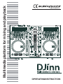
Multimedia platform for mixing and playback
DJinn - Multimedia platform for mixing and playback
EN
1 - Safety Instructions
Important Safety Information
This unit was created to operate in place heated and
insulated from any form of moisture or water spray.
Any use in wet locations, unprotected, or subjected to
temperature changes represent a significant low risk
to both the device for anyone nearby.
This device contains within its housing, uninsulated
portions under tension high enough to pose a risk of
electric shock. Do not under any circumstances per form maintenance on this unit when it is turned on.
Only the relevant technical services and recognized
by HITMUSIC are authorized to perform maintenance
on this unit. Routine maintenance actions must follow
the precautions in this manual
CAUTION : To reduce the risk of electric shock, never remove
the covers. There are no user-serviceable parts inside. Contact a
qualified service technician for maintenance of this unit.
Noise levels
Risk of electrocution
To prevent electric shock, do not use
extension cord, power strip or other system
without connecting metal parts in contact are
completely out of reach.
The sound systems are capable of delivering
a sound level (SPL) harmful to human health.
The sound pressure levels are apparently
noncritical damage hearing if the person is
exposed over a long period.
Do not park close to the speakers in operation.
Environmental Protection
• The environment is a cause that defends HITMUSIC, we sell only the products fit, conform to ROHS.
• Your product is composed of materials to be recycled, do not throw in your trash, bring it to a collection center set up
near your residence. The service centers you will resume your device at the end of life to proceed to its destruction in
compliance with environmental rules.
• For more information http://www.hitmusic.fr/directives-deee.php.
Symboles utilisés
IMPORTANT symbol indicates an
important recommendation for use.
The CAUTION symbol indicates a risk of product degradation.
The WARNING symbol indicates a risk of harm to the physical integrity of the
user and any other person present.
The product can also be damaged.
Page 2
DJinn - Multimedia platform for mixing and playback
EN
Instructions and recommendations
10 - Power supply :
This product works only on the voltage on a label
on the back of the product. If you are unsure of the
1 - Read the instructions :
voltage of your electrical installation, consult your
It is advisable to read all instructions and operating instructions
dealer or local power company.
before using the device.
2 - Retain instructions :
It is advisable to keep the instructions for use and operation
later.
3 - Consider the warnings :
It is advisable to carefully consider all warnings and
instructions for operating the product.
4 - Follow the instructions :
It is recommended that you follow all operating instructions
and use.
5 - Water and moisture :
Do not use near water, for example near a bathtub, sink or
basin, or in a damp place or near a swimming pool, etc.. ..
6 - Installation :
Do not place this product on a rolling stand, tripod, bracket
or table. The product may fall seriously injuring a child or
an adult and seriously damaged. Use only a cart, stand,
tripod, bracket or table recommended by the manufacturer
or sold with the apparatus. In any case to
install the equipment it is advisable to follow
the manufacturer's instructions and use
instruments recommended by it.
11 - Protection of Electrical cables:
You must ensure that electrical cables are not likely
to be walked on or pinched by items placed upon
or against, paying particular attention to plugs and
their exit point on the unit.
12 - Cleaning :
Unplug the unit before cleaning. Do not use attachments not
recommended by the manufacturer. Use a damp cloth on the
surface of the device. Do not pass the apparatus underwater.
13 - Period of no use :
Unplug the power cord of your appliance if you do
not use it for a long period.
14 - Penetration by objects or liquids :
Do not enter into any kind of objects into this
product through openings as they may cause fire
or electric shock.
Never spill liquid of any kind on the product.
15 - Damage requiring service :
Ask qualified persons in the following cases:
It is strongly advised to move with caution
when rolling the cabinet the unit is over. Quick stops, excessive - When the power cord or plug is damaged (e).
- If liquid has been spilled or objects have fallen
pushing and rough surfaces might topple the whole.
into the apparatus.
- If the product has been in contact with rain or
7 - Mount on a wall or ceiling :
water.
It is recommended that you contact your dealer prior to
- If the product does not operate normally by
installation.
following the instructions.
- If the product took a shock.
8 - Air exit :
Slots and openings in the cabinet are provided for ventilation,
16 - Maintenance / overhaul :
to ensure use of the product with confidence and to avoid
Do not attempt to review this product yourself.
overheating. These openings must not be blocked or covered.
This will expose you to dangerous voltage. Talk to
We must be careful to never block the openings by placing the
qualified personnel.
product on a bed, sofa, rug or other surface of this style. This
device should not be placed in an enclosed facility
such as a bag or rack unless aeration was provided
17 - Operating environment :
or the manufacturer's instructions were followed.
Temperature and humidity environment Operating:
5-35 °, relative humidity below 85% (vent not
9 - Heat :
blocked).
It is advisable to keep the product away from heat sources
Do not install the unit in a poorly ventilated area or
such as radiators, stoves, heat reflector or other products
in a place subject to high humidity or direct sunlight
(including amplifiers) that produce heat.
(or strong artificial light)
Page 3
DJinn - Multimedia platform for mixing and playback
EN
2 - Features
Auto cue
RCA output
Pitch display
Skid Effect
Real time cue
Filter Effect
Folder Search
Echo Effect
Fine Tune BPM
Flanger Effect
Cross Fader Curve
Relay Playback
Switching Power Supply
Mp3 Track Listings
Real Time Scratch Play
Fader Start Playback
2 External Phono/Line Input
1/75th second frame search
Plays Mp3's from either USB
MIDI interface Controller for PC
Master Output through USB Port
3 Band Kill EQ for Each Channel
Jog Wheel Sensitivity Adjustment
Jog Wheel Pitch Bend +/-100%
Mic Tone, Phones Cue Pan Control
Headphone Jack with Level Control
4 Programmable Cue (Bank) Buttons
Selectable Single or Continuous Play
Memory Backup, Defaults to last setting
8 different speed scan (4 Forward/4 Reverse)
Seamless Loop (uninterrupted loop playback)
Large bright VFD display can be viewed from wide angles
Adjustable Pitch Percentages: +/-6%, +/-10%, +/-16% & +16/-100%
Instant Start (sound is produced immediately when the PLAY button is pressed)
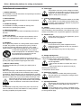
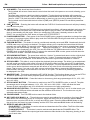
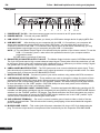
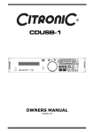
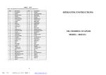
3 - Controls and functions
Top pannel
1
2
3
4
20 22
5
21 23
6
19
18
17
16
15
24 25
7
Page 4
8
14
9
13
10
11
12
Djinn - Multimedia platform for mixing and playback
EN
1. VFD DISPLAY – This high quality VFD display indicates all the functions, as they are occurring. The
display ICONS will be explained on VFD displaysection.
2. SEAMLESS LOOP
A BUTTON (IN BUTTON) – This function allows you to set a CUE POINT without music interruption.
This button also sets the starting point of a seamless loop.
B BUTTON (OUT BUTTON) – This button is used to set the ending point of a loop. A loop starting point
is set by pressing the A button. Pressing the B button set the loop ending point. The loop will continue
to play until the RELOOP button is pressed once again.
RELOOP BUTTON – If a SEAMLESS LOOP has been made, but the Player is not active in
SEAMLESS LOOP mode (a loop is not playing), pressing the RELOOP button will instantly reactivate
the SEAMLESS LOOP mode. To exit loop, press the RELOOP button.
IN/OUT POINT EDIT – In the LOOP mode, press B button, LED of B will flash an d display will show the
loop-out point time, now you can turn the jog wheel to edit OUT point. Then press the B button to exit
editing; or press the A button, LED of A will flash and “IN EDIT” will be indicated in the VFD, now you can
turn the jog wheel to edit IN point. Then press the A button to exit editing.
3. TRACK KNOB – This knob has three functions as below:
The knob is used to select a track. Turning track knob will forward/backward skip to next track.
Holding down and turning track knob will rapidly forward/backward skip through the tracks by 10 tracks
per click.
Press track knob to switch file name/title /artist /Album/Genre on the VFD.
4. SAVE BUTTON – This button can be used in couple of ways as below:
Press this button to activate the save mode, the SAVE button LED will glow when active. After the save
mode is activated, press your desired bank button to store your CUE point or playing loop.
To store your loops and cue points that are saved in the BANKS to the system memory for next time,
press the SAVE button for 1 second and the button flashes.
RECALL MEMORY : The player can store 4 programmed cue points or loops per track in the USB
device. The memory points in the USB device are depending on available memory space. These setting
may be recalled at any time, even when an audio source has been removed and loaded at a later time.
To recall the bank memory with USB device as following:
Press the SAVE button, the button is lighted up, and turns the TRACK knob to select the TRACK with
BANKS that you would like to recall for a cue point; or a loop when in the loop mode (press the
RELOOP button to activate loop mode).
5. X (FX1) BUTTON – This button is used to adjust the parameter time value. You can push the X button
(FX1), LED on, and turn the JOG WHEEL to adjust the parameter time value. If the HOLD function is not
active, any changes to the effect parameters will be momentary.
6. SEARCH/REAL-TIME CUTTING AND EXTENDING LOOP FUNCTION BUTTONS
This search button allows you to quickly scan backwards through a track.
This search button allows you to quickly scan forwards through a track.
During the loop playback, press the
SEARCH button, the loop playing time is cut in half each time the
button is pressed. The loop can be cut to 1/64 original loop length. Press the
SEARCH button, the loop
playing time is doubled each time the button is pressed. The loop can be extended to 16X original loop length.
7. JOG MODE BUTTONS – The jog wheel has 3 effect functions as below:
CUE MODE:
IN PLAYBACK MODE
While in play mode and when the touch sensitivity function is active, the JOG WHEEL can be used to
return the unit to last IN point.
Simply touch the JOG WHEEL and unit will immediately return to the last set CUE point and playback
without music interruption.
IN CUE MODE
While in cue mode and when the touch sens itivity function is active, tapping on the JOG WHEEL can
be used to start playback.
The unit will continue to playback until the JOG WHEEL is released. Once the JOG WHEEL is
released the unit will return to the last IN point.
VINYL MODE – When wheel mode is set to VINYL, use the JOG WHEEL to activate the scratch effect
by touching the surface of Jog Wheel.
CLASSIC MODE – When wheel mode is set to CLASSIC, scratch mode is exit, JOG WHEEL can be
used to pitch bend and frame search.
Page 5
EN
DJinn - Multimedia platform for mixing and playback
8. JOG WHEEL –This wheel has three functions:
The jog wheel will act as a frame search control when the track in the pause or cue mode, allowing you to
set a point.
The wheel also works as a pitch bend during playback. Turning the wheel clockwise will increase the
pitch percentage up to 100%, and turning the wheel counterclockwise will decrease the pitch percentage
down to -100%. The pitch bend will be determined on how long you turn the jog wheel continuously.
The jog wheel can be used with the hold of the X(TIME) and Y(RATIO) buttons to set effects parameter
adjustment
9. CUE/ BUTTON – Pressing the button will activate the CUE PLAY function and the music will play instantly
from the last cue point.
10. CUE BUTTON – Pressing the CUE button during playback immediately will pause playback and return the
track to the last set cue point; the CUE indicator will glow in the cue mode. The CUE button can be held
down to momentarily play the music. When you release the CUE button it instantly returns to the CUE
POINT. You can also tap the CUE button to create a STUTTER EFFECT.
11. PLAY/PAUSE BUTTON – Each press of the PLAY/PAUSE button causes the operation to change from play
to pause or from pause to play. While in play mode the PLAY/PAUSELED will glow and while in pause mode
the PLAY/PAUSE LED will flash.
12. TAP BPM BUTTON – This button is used to override and manually set a track BPM. Occasionally the builtin BPM meter may not function as desired. This button allows you to override the internal beat clock and
manually set a track BPMs. To manually set the BPMs; tap this button a few times to a tracks heavy down
beat, the unit will automatically calculate your
tapping and translate it i nto a tracks BPMs. The BPM
READOUT is then di splayed in the VFD. You can also hold the TAP BPM button and turn the TRACK or
FOLDER knob to adjust the BPM value. To return to the automatic BPM counter, press and hold down the
TAP button for at least 1 seconds and then release.
13. PITCH BEND BUTTONS – The speed rises while the “+button” is pressed and returns to the original pitch
when the button is released. The speed drops when the “–button” is pressed and returns to the original
pitch when the button is released. These buttons can be used to synchronize the beats of 2 tracks.
14. PITCH SLIDER – This slider is used to adjust the playback pitch percentage. The slider is a set adjustment
and will remain set until the pitch slider is moved or the pitch function has been turned off.This adjustment
can be made with or without a music source device in the player. The pitch adjustment will remain even if a
music source device has been removed and will reflect on any other music source device inserted into the
player. That is to say, if you set a +6% pitch on one music source device, remove the USB device and
insert another, that music source device too will have a +6% pitch. The amount of pitchbeing applied will
be displayed in the VFD.
15. MASTER TONE – This button activates the KEY LOCK function. This function allows you to use the PITCH
SLIDER to speed up or slow down playback speed without altering the tonal pitch of the track.
16. PITCH RANGE SELECTOR – Press this button to choose any pitch range percentages of 6%, 10%, 16%
and +16/-100%.
17. PITCH ON/OFF BUTTON – This button is used to turn the PITCH SLIDER function on and off. The pitch
percentage can be changed between +/-6%, 10%, 16% and +16%/-100%. -100% will allow the least
amount of pitch manipulation and 16% will allow the most amount of pitch manipulation.
18. SOURCE SELECT BUTTON – This button lets you toggle between USB Port 1 and 2. In other words, you
can select which USB port will be activated and the relational LED will be lit. The function can only be
selected under pause mode.
19. FOLDER KNOB – Turn FOLDER knob to search the desired folder.
20. HOT CUE/LOOP BANK 1~4 – These buttons are used to store either four cue points or four loops. Each
Bank button can store either a loop or a cue point. When the SAVE LED is lit, press the desired BANK
button to set a cue point, LED lit red, or a loop and LED lit green. Press the desired BANK button to play
the music from the stored cue point instantly and the LED of the activated BANK button will be flashing.
21. EFFECTS AND HOLD BUTTON
ECHO EFFECT – This button is used to activate and deactivate the Echo effect. The Echo effect adds
an echo to your output signal.
FLANGER EFFECT – This button is used to activate and deactivate the FLANGER effect. The
FLANGER effect distorts the output signal and creates an effect similar to the frequency phasing in and
out of each other.
Page 6
Djinn - Multimedia platform for mixing and playback
EN
HOLD BUTTON – This button allows you to lock any new parameter settings you set to the effects. The
button LED will glow when the hold function is selected. When the hold selection is not active, any
changes to the effect parameters will be moment.
FILTER BUTTON – This button is used to activate and deactivate the Filter effect. The Filter effect
tweaks the original sound to add different tonal definition. The effect is almost the same as the PHASE
effect.
SKID BUTTON – This button is used to activate and deactivate the Skid effect. The Skid effect
simulates the sudden platter stop of a turntable, like pressing the stop button on a turntable.
22. CLEAR BUTTON – Press CLEAR button, the button is lighted up, and then select the BANK buttons (1 ~ 4)
you would like to clear.
23. Y (FX2) BUTTON – This button is used to adjust the parameter ratio value. You can push the Y button and
turn the JOG WHEEL to adjust the parameter ratio value.
24. TIME BUTTON – The button will switch the time value described in the time meter between Elapsed
playing time and TRACK Remaining time.
25. SGL/CTN – This function allows you to choose between single track play and continuous track play (all
tracks in order). With this button you can also switch AUTO CUE on and off, by pressing it for at least 1
second.
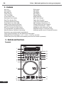
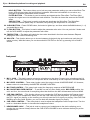
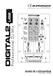
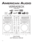
FRONT PANEL
Front pannel
1
2
3
4
5
6
7
1. MIC 1 JACK – This jack is used to connect a microphone to the mixer. Connect your microphone via 1/4
inch jack. The volume output level for microphone will be controlled by its own respective VOLUME KNOB.
2. MIC LEVEL CONTROL – These rotary knobs control the output volume of MICROPHONE 1/2. However,
master volume is controlled by the MASTER VOLUME CONTROL.
3. MIC TONE CONTROL – This rotary knob control the frequency response of MICROPHONE.
4. MIC ON/OFF/MIC OVER SWITCH – To set MIC on and off, when switch at the MIC OVER position, the
mic1 and 2 on, the sound level for everything other than that from the MIC will decrease to around 20dB.
5. CUE PAN CONTROL – This function allows you to monitor the CUE level as well as the Program (main
output) level in your headphones. When you turn the CUE PAN to the full left position, you will only hear
the CH 1 signal you playing, on the contrary you will only hear the CH 2 signal you playing. If the CUE PAN
KNOB is set to the center position, you can cue both the channels signal you playing.
6. CUE LEVEL CONTROL – This rotary knob is used to adjust the headphone volume output level. Turn the
knob in a clockwise direction to increase the headphone volume.
7. HEADPHONES JACK – This jack is used to connect your headphones to the device allowing you to
monitor the cue channel. Always be sure the CUE LEVEL VOLUME is set to minimum before you put the
headphones on.
Page 7
DJinn - Multimedia platform for mixing and playback
EN
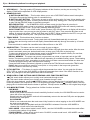
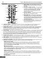
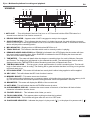
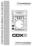
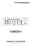
Mixer pannel
13
1
12
2
3
11
4
1. USB 1 PORT – This is the USB port where you
insert your USB mass storage device for playing
MP3 files.
2. MASTER VOLUME CONTROL – This rotary knob
is used to control the master output level
(volume). To avoid distorted output try to maintain an average output signal level +4 dB. Be
sure this volume control is always set to zero
before turning the unit on.
3. BOOTH CONTROL – This rotary knob is used to
adjust the level of the BOOTH outputs.
5
6
10
7
9
4. RELAY BUTTON – This button is used to switch
the RELAY on and off. The left and right players
will automatically be in the single play mode when
the relay function is activated. On the contrary, the
left and right players will automatically be in the
continuous play mode.
5. MASTER METER BUTTON – This button is used
to choose between master level indicators and
channel level indicators.
8
6. CHANNEL FADER – These faders are used to control the output signal of any source assigned to its
particular channel. However, master volume is controlled by the MASTER VOLUME CONTROL.
7. FADER START SWITCH – This function works in conjunction with a compatible player. When used with a
compatible player, you can use the crossfader to start and stop a player with the mixer’s crossfader. The
ON/OFF switch activates the FADER START feature. If this function is activated, the FADER START
automatically returns the player to the preset cue point.
8. CROSSFADER – This fader is used to blend the output signals of channels 1 and 2 together. When the fader
is in the full left position (channel 1), the output signal of channel 1 will be controlled by the master volume
level. The same fundamentals will apply for channel 2. Sliding the fader from one position to another will
vary the output signals of channels 1 and 2 respectively. When the crossfader is set in the center position,
the output signals of both the channel 1 and channel 2 will be even.
9. XFADER CURVE SWITCH – Allows adjusting the “shape” of the crossfader response from a gentle curve for
smooth, long running fades, to the steep pitch required for top performance cut and scratch effects.
10. LEVEL METER – The dual LED’s indicators are used to detail either the master output level, a combination
of the master output level or the PGM monaural level.
11. CHANNEL EQ CONTROL – Both of the channels include a three-band signal EQ. These controls are used
to increase or decrease the HI’s, MID’s, LOW’s and frequency of the output signal.
HIGH frequency control
This knob is used to adjust the high levels of a channel allowing for a maximum high gain of 10dB or
maximum decrease of –35dB. Turning the knob in a counter- clockwise direction will decrease the
amount of high applied to a channel signal, turning the knob in a clockwise direction will increase the
amount of high applied to a channel signal.
MID frequency control
This knob is used to adjust the midrange levels of a ch annel allowing for a maximum midrange gain of
10dB or maximum decrease of –35dB. Turning the knob in a counter-clockwisedirection will decrease the
amount of midrange applied to a channel signal, turning the knob in a clockwise direction will increase the
amount of midrange applied to a channel signal.
LOW frequency control
This knob is used to adjust the low levels of a channel allowing for a maximum bass gain of 10dB or
maximum decrease of -35dB. Turning the knob in a counter-clockwise direction will decrease the amount
of low applied to a channel signal, turning the knob in a clockwise direction will increase the amount of
low applied to a channel signal.
KILL EQ control
Press the EQ knob to activate the KILL function to the lowest level “-35dB”.
Page 8
Djinn - Multimedia platform for mixing and playback
EN
12. CHANNEL GAIN CONTROL – This adjustment is used to adjust an audio source signal input gain for a
channel. Never use the gain control to adjust output volume. Setting the gain level properly will ensure a
clean output signal. To properly set the gain level controls:
(1) Be sure the MASTER VOLUME CONTROL is set to minimum.
(2) Set the CHANNEL FADER to level 7.
(3) Begin play on an audio source connected to the channel you are adjusting.
13. SOURCE SELECTOR SWITCH – These switches are used to s elect the input source assigned to each
channel. Each channel may only be assigned one input source at a time.
CH1 selected to PC + CH2 selected to PC – the entire unite works as a MIDI controller.
CH1 selected to PC + CH2 selected to DECK B – the Deck A works as a MIDI controller, the mixer works
internally with Deck B.
CH1 selected to PC + CH2selected to LN2/ PH2 –the Deck A works as a MIDI controller, the mixer works
internally with LN2/PH2 input.
Source
Condition
CH1
DECK A DECK A
CH2
DECK B
DECK A
L1/P1
L1/P1
L1/P1
PC
PC
PC
PC
DECK B
L2/P2
PC
DECK B
L2/P2
PC
DSP Input 1
—
DSP Input 2
—
—
—
L1/P1
L1/P1
L1/P1
L2/P2
USB Input 2
—
L2/P2
USB Input 2
DSP Output 1
REC
REC
REC
REC
REC
REC
L2/P2
DSP Output 2 PHONES PHONES PHONES PHONES PHONES PHONES
USB Output 1
USB Output 2
L2/P2
L2/P2
USB Input 1 USB Input 1 USB Input 1
—
L2/P2
USB Input 2
REC
REC
REC
PHONES
PHONES
PHONES
L1/P1
L1/P1
L1/P1
L2/P2
Page 9
DJinn - Multimedia platform for mixing and playback
EN
Rear pannel
1
2
3
4
5
6 7
8
9
10 11
1. POWER INLET (AC IN) – Use the accessory power cord to connect to an AC power outlet.
2. POWER SWITCH – Turn this unit power ON/OFF.
3. USB 2 PORT–This is the USB port where you insert your USB mass storage device for playing MP3 files.
4. USB MIDI PORT – After hooking up your computer with the USB 1.1 Connections, your computer will
detect them respectively as an external sound card (USB Code). You may either play music on your
computer or send it via the USB 1.1 Connections as a signal source to the device; alternatively, you may
record the Master output signal on your computer using the USB 1.1 Connection.
NOTE: (1) The sent Master Output Signal is not influenced by the position of the volume controls. To use the
USB 1.1 Connection, pleas e also refer to the operation manual of your computer and the
programmers used.
(2) USB cable no more than 3 feet long.
5. BALANCED XLR MASTER OUTPUT JACKS – The Master Output includes a pair of XLR Balanced jacks.
The 3-pin XLR jacks send a high current balanced output signal. These jacks should be used when you will
be driving an amp or other audio equipment with a balanced input, or whenever you will be running a signal
line greater than 15 feet. Always, use these jacks whenever possible.
6. UNBALANCED MASTER OUTPUT – The RCA jacks send a low current unbalanced output signal. These
jacks should only be used for shorter cable runs to signal processors or looping to another mixer. For cable
runs greater than 15 feet use the XLR BALANCED JACKS.
7. BOOTH OUTPUT JACKS – Connect to inputs of your active monitors using cables with RCA connectors.
8. LINE/PHONO SELECTOR SWITCH – These switches are used to change the voltage line levels of there
respected LINE/PHONO RCA inputs jacks. When connecting turntables with magnetic cartridges to these
jacks be sure the corresponding switch is in the PHONO” position, and when using line level input devices
be sure the switch is in the “LINE” position. CAUTION: Always be sure main power is shut off before
change the position of the Line Level Selector Switch.
9. CHANNEL LINE/PHONO INPUT CONNECTORS – Turntables equipped with MM pickup cartridge (All DJ
turntable use MM pickup cartridges) may be connected to these jacks as long as the LINE/PHONE selector
switches is in the “PHONE” position. CD players, Tape Decks and other line level instruments may only be
connected to these jacks as long as the LINE/PHONE selector switches are in the “LINE” position. Input
volume will be controlled by the Channel gain control knob.
10. GND (GROUND TERMINAL) – Be sure to connect turntable ground leads to either or both of the two
available ground terminals. This will reduce the humming and popping noises associated with magnetic
phono cartridges.
11. MICROPHONE 2 JACK – This combo jack will accept a standard 1/4 plug or XLR 3-pin balanced male
plug. The volume output level for microphone will be controlled by its own respective VOLUME KNOB.
Page 10
Djinn - Multimedia platform for mixing and playback
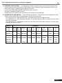
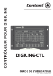
VFD DISPLAY
18
17
16 15
EN
14
13
12
11
1
2
3
10
4
9
5
6
7
8
1. AUTO CUE – This will indicate if the Auto Cue is on or off. Press and hold the SGL/CTN button for 1
second to turn the Auto Cue function on and off.
2. RELOOP INDICATOR – Appears when LOOP is engaged or ready to be engaged.
3. SINGLE INDICATOR – This indicates that the player is in single play mode; the track will play once and
return to CUE mode. If the single indicator is not on, the unit is in continuous mode. In continuous mode the
device will play all the remaining tracks.
4. MP3 INDICATOR – Displays when a USB device has MP3 files on it.
5. TRACK DISPLAY - This indicator describes which track is currently cued or is playing.
6. REMAIN/ELAPSED INDICATOR
- When REMAIN is indicated in the VFD Display the time meter will show
the current track's remaining time. When ELAPSED is indicated in the VFD Display the time meter will
show the current track's elapsed time.
7. TIME METER – The meter will detail either the elapse or remaining time of a track in Minutes, Seconds
and Frames. The display time will depend on the selected time mode. The selected time function will be
displayed above the TIME METER as either Remaining track time or Elapsed track Time.
8. TIME BAR INDICATOR – This bar gives a visual approximation of a track's remaining time. This bar will
begin to flash when a track is ending. The flashing bar is great reminder that time is running out to get that
next track ready to go.
9. PITCH INDICATOR – This meter will indicate how much pitch is either being applied or will be applied.
10. KEY LOCK – This will indicate the KEY Lock function is active.
11. MEMORY BUCKET – This meter serves two functions.
(1) The bucket outline indicates your cue memory status. a full outline lets you know the cue memory is full.
(2) The five bars inside the bucket represent the digital buffer. Each bar represents 2 seconds.
12. BPM METER – This meter will display the BPM's of the current track.
13. AUTO BPM – This will indicate that the AUTO BPM counter is active.
14. ALPHANUMERIC DISPLAY – Indicates the current name of the track, of the folder. All kinds of other
interactive information are also shown.
15. FOLDER DISPLAY – This indicates which folder you are in.
16. TOUCH INDICATOR – This appears when anything touches the jog wheel.
17. CUE INDICATOR – This indicator will glow when the unit is in CUE mode.
18. PLAY/PAUSE INDICATOR – Indicates the player is in play mode (" "), or the player is in pause mode (" ").
Page 11
DJinn - Multimedia platform for mixing and playback
EN
4 - Internal menu
Hold the FOLDER knob for 2 seconds to enter the internal menu, and turn FOLDER knob to search through
the different menu.
Turn the TRACK KNOB; or turn Jog Wheel to change the submenus.
Save and exit internal menu, turn the FOLDER knob to F. Exit & Save and press the TRACK knob, the display
indicates “Saving”.
NOTE: Anytime you can exit the internal menu just press the FOLDER knob. However, the modified setting
would not be saved.
1. Playlist – Normal / Title/ Artist / Album/ Genre
The DATABASE BUILDER can generate “Playlist” for USB device. You can adjust various criteria in order
to filter track in this setting.
You can turn the TRACK knob to select “Normal / Title/ Artist / Album/ Genre” and press the FOLDER knob
again to memorize your setting and exit the internal menu.
Normal: This is the default setting. The tracks are played corresponding to the established hierarchical
data structure.
Title: It is possible to continuously and alphabetically browse track database through the title structure.
Artist: It is possible to continuously and alphabetically browse track database through the Artist’s name
structure.
Album: It is possible to continuously and alphabetically browse track database through the Album structure.
Genre: It is possible to continuously and alphabetically browse track database through the Genre structure.
2. Repeat Mode – 3 different mode: Play All repeat/ Folder/Track
3. MIDI CH – Setup MIDI Channel from 1 to 16 (deck A – mixer – deck B).
4. MIDI Setup
TAP =HOLD/TOGGLE
I/O = Hide/ DIS. (hide/display MIDI I/O value)
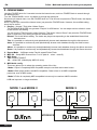
5. MIDI/Audio config
This menu allows you to select the operating mode of the Jinn:
- Mode 1: Djinn is completely MIDI compatible except cross fader and master button.
- Mode 2: Both player buttons are MIDI compatible. Center mixer is not MIDI compatible
(real mixer even in MIDI mode)
- Mode 3: DJinn is completely MIDI compatible but can only be used as a MIDI controller.
USB and Input are no longer available.
MODE 1 and MODE 2
DECK 1
MIXER
MODE 3
DECK 2
DECK 1
MIXER
DECK 2
SOFTWARE
CUE
MASTER
INTERFACE
CUE
Page 12
Djinn - Multimedia platform for mixing and playback
EN
6. Cross Fader
Lock =To lock the crossfader in the middle of two channel.
Unlock=The crossfader is back to normal status.
7. Cross Fader Reverse
ON =Reverse the crossfader
OFF =Normal mode
9. Display Time – 0.5 ~ 12.0 sec. (line name start/stop time adjustment)
10. Scroll Speed – 50 ~ 2000 msec. (line name move time adjustment)
A. Sensitivity – Touch Wheel Sensitivity Adjustment (Adjustment range is -20~+20).
B. PITCH BEND – SPEED=1 ~ 50. The pitch bend parameter determines the impact of the jog wheel on the
pitch bend function. The player comes with the pitch bend parameter set to 25. You can adjust the parameter
between 01 (very little impact) to 50 (extreme impact) to adapt the pitch bend function perfectly to your
personal taste.
C. Intensity – VFD Brightness (Brightness range is 1~4)
D. A.Cue Level – Change the AUTO CUE level (Level range is -36~-78dB)
E. Bite Rate –Display ON/OFF.
F. Version – CXX (Control version)
DSPXX (DSP version)
G. Load Defaults – Press track knob to enter load defaults.
H. Exit & Save – Exit & Save setting to next power on (Press the TRACK KNOB to exit & save in any operating
mode
Note:
Save: U1/U2, PITCH ON/OFF, PIT CH RANGE, SGL/CTN, AUTO CUE, TIME MODE, HOLD, KEY LOCK,
EFFECTS ON/OFF, PLAYLIST, REPEAT MODE, MIDI CHANNEL, MIDI SETUP, CROSSFADER,
CROSSFADER REVERSE, DISPLAY TIME, SCROLL S PEED, SENITIVITY, INTENSITY, A.CUE LEVEL,
DISPLAY
Defaults: U1/U2(U1), PITCH (OFF), PITCH RANGE (10%), SGL/CTN(CTN), AUTO CUE(ON), TIME MODE
(REMAIN), HOLD(OFF), KEY LOCK(OFF), EFFECTS(OFF), PLAYLIST (NORMAL), REPEAT MODE(ALL),
MIDI CHANNEL(1-2-3), MIDI SETUP(TAP=HOLD, I/O=HIDE), CROSSFADER(UNLOCK), CROSSFADER
REVERSE(Off), DISPLAY TIME(3sec), SCROLL SPEED(400ms), SENITIVITY(0), INTENSITY(4), A.CUE
LEVEL(-48dB),Bit rate display(ON)
Page 13
Djinn - Multimedia platform for mixing and playback
EN
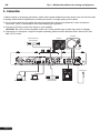
5 - Connection
1. Before making or changing connections, switch off the power anddisconnect the power cord from the AC outlet.
2. Quality cables make a big difference in fidelity and punch. Use high-quality, audio cables.
3. Do not use excessively long cables. Be sure plugs and jacks are securely fastened. Loose connections
cause hum, noise, or intermittence that could damage your speakers.
4. Connect the RCA pin cords to the inputs on your amplifier.
CAUTION : Be sure to use the supplied control cord. Using another type of cable may result in damage.
5. Connecting to a Computer– Support computer operating systems include Windows Vista, Window XP, and
MAC OS X or later.
Turntable
Speaker
Mainunbalanced
poweramplifier
Microphone
USBStorageDevice
Page 14
Computer
Mainbalanced
poweramplifier
CD/MP3Player
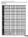
FUNCTION
FUNCTION CODE
(DECK A)
05/17
01/16
02/02
03/03
04/04
06/06
07/07
08/08
30
09/09
31
0A/0A
32
0B/0B
33
0C/0C
Type
SW/ENC
SW/ENC
SW/LED
SW/LED
SW/LED
SW/LED
SW/LED
SW/LED
(Rouge)
LED
(Vert)
SW/LED
(Rouge)
LED
(Vert)
SW/LED
(Rouge)
LED
(Vert)
SW/LED
(Rouge)
LED
(Vert)
SW/LED
C0
D#3
B-1
D3
A#-1
C#3
A-1
C3
G#-1
G-1
F#-1
E-1
D#-1
D-1
CC/Note
4B
4A
49
48
47
46
45
43
42
41
40/55
44/56
SHIFT
(Hold TAP)
0C/0C
33
0B/0B
32
0A/0A
31
09/09
30
08/08
07/07
06/06
04/04
03/03
02/02
01/26
05/27
FUNCTION CODE
(DECK B)
C0
D#3
B-1
D3
A#-1
C#3
A-1
C3
G#-1
G-1
F#-1
E-1
D#-1
D-1
CC/Note
4B
4A
49
48
47
46
45
43
42
41
40/65
44/66
SHIFT
(Hold TAP)
7FH : ON
00H : OFF
7FH : ON
00H : OFF
7FH : ON
00H : OFF
7FH : ON
00H : OFF
7FH : ON
00H : OFF
7FH : ON
00H : OFF
7FH : ON
00H : OFF
7FH : ON
00H : OFF
7FH : ON
00H : OFF
7FH : ON
00H : OFF
7FH : ON
00H : OFF
7FH : ON
00H : OFF
7FH : ON
00H : OFF
7FH : ON
00H : OFF
7FH : ON
00H : OFF
7FH : ON
00H : OFF
ACTION
Djinn - Multimedia platform for mixing and playback
EN
6 - MIDI MAP
DECK A and DECK B
Page 15
Page 16
JOG
/
FUNCTION
FUNCTION CODE
(DECK A)
0D/0D
0E/0E
0F/0F
10/10
11/11
12/12
13/13
14/14
15/15
16
17
18/18
19/19
1A/1A
1B
1C
1D/1D
27/18
Type
SW/LED
SW/LED
SW/LED
SW/LED
SW/LED
SW/LED
SW/LED
SW/LED
SW/LED
SW
SW
SW/LED
SW/LED
SW/LED
SW
SW
SW/LED
SW/ENC
F1
D1
C#1
C1
A0
G#0
G0
F#0
F0
E0
D#0
D0
C#0
CC/Note
66/57
5C
5B
5A
59
58
57
56
55
54
53
52
51
50
4F
4E
4D
4C
SHIFT
(Hold TAP)
27/28
1D/1D
1C
1B
1A/1A
19/19
18/18
17
16
15/15
14/14
13/13
12/12
11/11
10/10
0F/0F
0E/0E
0D/0D
FUNCTION CODE
(DECK B)
F1
D1
C#1
C1
A0
G#0
G0
F#0
F0
E0
D#0
D0
C#0
CC/Note
66/67
5C
5B
5A
59
58
57
56
55
54
53
52
51
50
4F
4E
4D
4C
SHIFT
(Hold TAP)
7FH : ON
00H : OFF
7FH : ON
00H : OFF
7FH : ON
00H : OFF
7FH : ON
00H : OFF
7FH : ON
00H : OFF
7FH : ON
00H : OFF
7FH : ON
00H : OFF
7FH : ON
00H : OFF
7FH : ON
00H : OFF
7FH : ON
00H : OFF
7FH : ON
00H : OFF
7FH : ON
00H : OFF
7FH : ON
00H : OFF
7FH : ON
00H : OFF
7FH : ON
00H : OFF
7FH : ON
00H : OFF
7FH : ON
00H : OFF
7FH : ON
00H : OFF
ACTION
EN
Djinn - Multimedia platform for mixing and playback
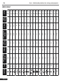
MIDI MAP
11
12/24/29/24
13/25/2A/25
14/26/2B/26
VR
VR/SW
CENTER/LED
VR/SW
CENTER/LED
VR/SW
CENTER/LED
1
2E
PITCH BEND / 28
VR
CENTER
LED
23
SW
2D
22
SW
LED
21/21
SW/LED
2C
20/20
SW/LED
LED
1F/1F
SW/LED
10
1E
SW
VR
FUNCTION CODE
(DECK A)
Type
LEVEL METER
LEVEL
LED
METER LED
Channel
Fader
Pitch Slider
FUNCTION
A#2
A2
G#2
D2
C#2
C2
A1
G#1
G1
CC/Note
4F
53/65/6A
52/64/69
51/63/68
50
67
62
61
60
5F
5E
5D
SHIFT
(Hold TAP)
1
2E
2D
2C
20
24/26/2B/26
23/25/2A/25
22/24/29/24
21
PITCH BEND / 28
23
22
21/21
20/20
1F/1F
1E
FUNCTION CODE
(DECK B)
A#2
A2
G#2
D2
C#2
C2
A1
G#1
G1
CC/Note
5F
63/65/6A
62/64/69
61/63/68
60
67
62
61
60
5F
5E
5D
SHIFT
(Hold TAP)
00H ~ 7FA
*
7FH : ON
00H : OFF
7FH : ON
00H : OFF
7FH : ON
00H : OFF
VR : 00~7F
VR : 00~7F
VR : 00~7F
VR : 00~7F
VR : 00~7F
7FH : ON
00H : OFF
7FH : ON
00H : OFF
7FH : ON
00H : OFF
7FH : ON
00H : OFF
7FH : ON
00H : OFF
7FH : ON
00H : OFF
7FH : ON
00H : OFF
ACTION
Djinn - Multimedia platform for mixing and playback
EN
MIDI MAP
Page 17
Djinn - Multimedia platform for mixing and playback
EN
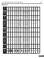
MIDI MAP
FONCTION
Cross Fader
SLIDER
(ON) L
(OFF) L
(ON) R
(OFF) R
(L)
(C)
(R)
Page 18
Type
Code de la Fonction
(MIXAGE CENTRAL)
CC/Note
SHIFT
(Hold TAP)
ACTION
SW/LED
37/37
G3
76
7FH : ON
00H : OFF
SW/LED
38/38
G#3
77
7FH : ON
00H : OFF
VR
31
70
VR : 00~7F
VR
32
71
VR : 00~7F
VR/SW/SW/CENTER
30/08/09/0A
6F/47/48/49
VR : 00~7F
VR
35
74
VR : 00~7F
VR
36
75
VR : 00~7F
VR
34
73
VR : 00~7F
VR
33
72
VR : 00~7F
SW
1
40
7FH : ON
00H : OFF
SW
2
41
7FH : ON
00H : OFF
SW
3
42
7FH : ON
00H : OFF
SW
4
43
7FH : ON
00H : OFF
SW
7
46
7FH : ON
00H : OFF
SW
6
45
7FH : ON
00H : OFF
SW
5
44
7FH : ON
00H : OFF
Djinn - Multimedia platform for mixing and playback
EN
MIDI MAP
CC-ABSOLUTE (VR, LEVEL METER LED) TYPE
Control Change messages are sent with status 0xBn, where n is the channel, for the specified CC controller.
Thus the controller MIDI ID is indicated with the
channel along with the CC number. The value from 0x00 to 0x7F, directly related to the location of the controller.
LEVEL METER LEDS
00~0B => ALL LEDS OFF
0C~17=>LED(-30) ON
18~23=>LED(-30, -20) ON
24~2F=>LED(-30, -20, -10) ON
30~3B=>LED(-30, -20, -10, -7) ON
3C~47=>LED(-30, -20, -10, -7, -4) ON
48~53=>LED(-30, -20, -10, -7, -4, -2) ON
54~5F=>LED(-30, -20, -10, -7, -4, -2, 0) ON
60~6B=>LED(-30, -20, -10, -7, -4, -2, 0, +2) ON
6C~77=>LED(-30, -20, -10, -7, -4, -2, 0, +2, +4) ON
78~7F=> ALL LEDS ON (-30, -20, -10, -7, -4, -2, 0, +2, +4, +7)
CC-RELATIVE (ENC) TYPE
Control Change messages are status 0xBn, where n is the channel, for the specified CC controller.
Thus the controller MIDI ID is indicated with the channel along with the CC number.
The value from 0x40 to indicate the change in the controller.
This is an offset to 0x40 “one’s complement” notation.
A message with data 0x43 indicates a positive change of 3.
A messages with data 0x31 indicates a negative change of 15.
SWITCH ON/OFF (SW, CENTER TYPE)
These messages are used for switches.
Control Change messages are sent with status 0x9n, SWITCH On and Off value are 0x7F and 0x00,
where n is the channel.
LED ON/OFF (LED TYPE)
These messages are used for LED.
Control Change messages are sent with status 0x9n, LED On and Off value are 0x7F and 0x00,
where n is the channel.
Page 19
EN
Djinn - Multimedia platform for mixing and playback
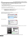
7 - Specific ASIO Driver Installation (Windows ® only)
7.1 - Installing the Djinn ASIO driver
• Before installing the ASIO driver, connect the Djinn to your computer and let the device recognition
procedure scroll down. A message will indicate that the hardware is recognized and ready for use.
•The ASIO forDjinn is not supplied with the Djinn.
To get it, then go to www.hitmusic.fron the page of Djinn.
•In the download area of this page, download the archive for the version of your operating system :
- AUDIOPHONY_DJinn_WIN32_2.9.25.zip for 32-bit
- AUDIOPHONY_DJinn_X64_2.9.25.zip for 64-bit
•Unzip the downloaded archive on your system.
•Open the folder where the archive was unpacked and run «Setup.exe».
•Select the language of your choice.
•Click «Install Driver».
•The driver installation starts.
•Windows 7 UAC checks each installation process, so at regular intervals dialog boxes ask you toconfirm
the facilities of thevarious parts of the driver. Click «YES» every time.
•At the end of the installation, you must restart the computer for the changes to take effect.
Page 20
Djinn - Multimedia platform for mixing and playback
EN
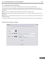
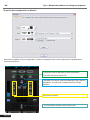
7.2 - Configuring Virtual DJ with Djinn
Connect your Djinn in your computer's USB (ASIO drivers and Virtual DJ must be installed).
• Your Djinn has 3 modes of operation are accessible from the Audio MIDI MENU Djinn: Press Folder of
your Djinn for 3 seconds. Use the dial to access the Folder option 5. Midi / Audio Config The three modes
available are:
Mode 1: Djinn is completely MIDI compatible except cross fader and master button.
Mode 2: Both player buttons are MIDI compatible. Center mixer is not MIDI compatible (real mixer even in
MIDI mode)
Mode 3: DJinn is completely MIDI compatible but can only be used as a MIDI controller. USB and Input are
no longer available.
These three configurations have the same management and audio streams require a specific configuration.
Virtual DJ best configuration for Mode 1 :
Page 21
EN
Djinn - Multimedia platform for mixing and playback
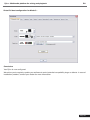
Virtual DJ best configuration for Mode 2 :
Note that in addition to this configuration, mode 2 requires that the volume gains and Crossfaders are
resolved as follows:
The gains must be adjusted to avoid saturation.
The AGC should be set to ON.
The MASTER volume must be reasonably high (without
saturation), the volumes of tracks must be in high
position.
EQ must be central
The crossfader position should be central
Page 22
Djinn - Multimedia platform for mixing and playback
EN
Virtual DJ best configuration for Mode 3 :
Conclusion
Your Djinn is now configured.
We advise you to regularly update your software to avoid potential compatibility bugs or defects. In case of
installation problem, contact your dealer for more information.
Page 23
EN
Djinn - Multimedia platform for mixing and playback
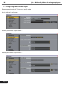
7.3 - Configuring TRAKTOR with Djinn
Recommended modes for Traktor are 2 and 3 modes
Audio settings for all modes :
Routing parameters Output Mode 2 :
Routing parameters Output Mode 3 :
Page 24
Djinn - Multimedia platform for mixing and playback
EN
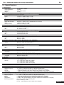
8 - Specification
1 - General section
Power supply
Power consumption
Dimensions
Weight
AC 100-240V ~ 50/60Hz
21 Watts
420 x 298,8 x 89 mm
4,42 Kg
2 - Input / Output impedance & Sensitivity (Eq. flat, maximum gain, Load : 100 KOhms)
2-1 Input impedance and reference input level
Line
Phono
Mic
47 KOhms / -14dBv (200mV) +/-0,1dB
47 KOhms / -50dBv (3,16mV) +/-0,1dB
10 KOhms / -50dBv (3,16mV) +/-0,1dB
2-2 Output impedance and level
Master
Master Bal. (600 Ohms)
Booth
Phone (32 Ohms)
1 KOhms / 0 dBv (1V) +/-2 dB
600 Ohms / +4 dBm (1,23V) +/-3dB (Between Hot and Cold)
1 KOhms / 0 dBv (1V) +/-2 dB
33 Ohms / 0 dBv (1V) +/-2 dB
3 - Frequency response (Eq flat, maximum gain, Load : 100 KOhms)
Line
Phono
Mic
20 - 20 Khz +/-2 dB
20 - 20 Khz +2/-3 dB (RIAA)
20 - 20 Khz +2/-3 dB
4 - THD + N (Eq flat, Maximum gain, Load : 100 KOhms, w/20kHz LPF, A-weighted)
Line
Phono
Mic
Less than 0,06% @ 1 KHz
Less than 0,08% @ 1 KHz
Less than 0,15% @ 1 KHz
5 - Maximum input (1KHz, THD=1%, Eq flat, Maximum gain, Load : 100 KOhms)
Line
Phono
Mic
More than +0dBv
More than -36dBv
More than -36dBv
6 - Maximum output (1KHz, THD=1%, Eq flat, Maximum gain, Load : 100 KOhms)
Master
Phones
More than +15dBv (5,62V) Load 100 KOhms
More than +4dBv (1,6V) Load 32 Ohms
7 - S/N ratio (Eq flat, Maximum gain, w/20kHz LPF, A-weighted)
Line
Phono
Mic
More than 73dB
More than 73dB
More than 63dB
8 - Crosstalk ( Eq flat, Maximum gain, Master = 0 dBv output, w/20kHz LPF, A-weighted)
Line, Phono
More than 63dB @ 1 KHz between L an R channel
More than 70dB @ 1 KHz between channels
9 - Fader kill (Eq flat, Maximum gain, Master = 0 dBv output, w/20kHz LPF, A-weighted)
Channel fader
Crossfader
More than 70dB @ 1 KHz
More than 70dB @ 1 KHz
10 - Tone, EQ
Mic
-14 +/-3 dB @ 100Hz
- 12 +/-3 dB @ 10 KHz
Channel
+10 +/-2 dB, below -35dB @ 70 Hz (BASS)
+10 +/-2 dB, below -35dB @ 1 KHz (MID)
+10 +/-2 dB, below -35dB @ 13 KHz (HIGH)
11 - Channel balance
Within 2 dB
12 - Talk Over
-20 dB +/-2dB
13 - USB host player (Mp3 format, 128 Kbps)
Output level
0 dBv +/-2 dB (TCD782 TKR16, Maximum gain, Eq flat)
Frequency response
17 - 16 KHz +/-2 dB (TCD781 TKR1,4,16, Set gain to 0 dBv, Eq flat)
THD+N
< 0,08% (TCD782 TKR16, Maximum gain, Eq flat, w/20kHz LPF, A-weighted)
S/N ratio
> 70 dB (TCD782 TKR2,8, Set gain to 0 dBV, Eq flat, w/20kHz LPF, A-weighted)
LR separation
> 63 dB at 1 Khz (TCD782 TKR2,9,11 Set gain to 0 dBV, Eq flat, w/20kHz LPF, A-weighted)
14 - USB host player section (Mp3 Format, 128 Kbps)
Output Level
0 dBv +/-2 dB (TCD782 TKR16, Maximum gain, Eq flat)
17 - 16 KHz +/-2 dB (TCD781 TKR1,4,16, Set gain to 0 dBV, Eq flat)
Frequency response
< 0,08% (TCD782 TKR16,Maximum gain, Eq flat, w/20kHz LPF, A-weighted)
THD+N
> 70 dB (TCD782 TKR2,8,Set gain to 0 dBV, Eq flat ,w/20kHz LPF, A-weighted )
S/N ratio
> 63 dB at 1 Khz (TCD782 TKR2,9,11 Set gain, to 0 dBV Eq flat, w/20kHz LPF, A-weighted)
LR separation
Recording & playback
(Line 1 KHz, -14 dBV input, Maximum gain)
Output : 6 dBV (2V) +/-2 dB
THD+N : < 0,08% ( Maximum gain , w/20kHz LPF, A-weighted)
Page 25
Djinn - Multimedia platform for mixing and playback
EN
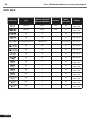
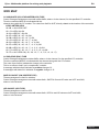
9 - Mp3 Format
USB Format
MP3 Format
Page 26
File System
Applicable file extensions
Max. number of Folders
Max. number of files
MPEG 1 Layer 3 standard (ISO/IEC
11172-3), which provides for single
channel (‘mono’) and two-channel
(‘stereo’) coding at sampling rates of 32
and 44.1kHz.
MPEG 2 Layer 3 standard (ISO/IEC
13818-3), which provides for similar
coding at sampling rates of 16, 22.05
and 24 kHz.
MPEG 2.5 Layer 3 standard, which
provides for similar coding at sampling
rates of 8, 11.025 and 12 kHz.
FAT 12/16/32
mp3. MP3. mP3. Mp3
999
Max. 999 files
32/40/48/56/80/96/112/128/160/192/224/
256/320 kbps
Xing/VBRI VBR
32/40/48/56/64/80/96/112/144/160 Kbps
Xing/VBRI VBR
32/40/48/56/64/80/96/112/144/160 Kbps
Xing/VBRI VBR
Djinn - Multimedia platform for mixing and playback
EN
10 - Notes
Page 27
AUDIOPHONY® company is always improving the quality of the products. Some modifications may be apply to
the product without notice. That’s why specifications and features can be different than those on this manual. To
be sure to have the last release of firmware and instructions check the web site www.hitmusic.fr