1
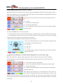
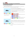
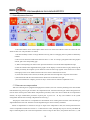
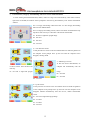
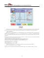
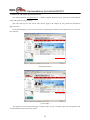
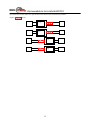
APLBODA Four Wheel Alignment
User manual
Index
一、Equipment operate and use
1、Equipment important notes
2、Major alignment system parts
3、Installation and Debug
4、Equipment operation and use of steps
1)Select vehicle specifications data
2)Level Measuring Heads
3)Measure alignment measurement data
4)Rear Wheel Adjustment
5)Front Wheel Adjustment
6)Save and print customer data
5、Advanced function Instructions
1) Jack-and-Hold Camber/Caster adjustment
2) Passat B5, Audi A6 constant value measured before the beam adjustment
3) Shim adjustment function
4) Rims uneven compensation
5) Professional, Largely Surrounding and Low Floor Measurements
6) Rapid alignment measurement
7) Turning 20°measuring Caster/SAI on Mechanical Turntable
6、Customer profiles Management
7、Add Vehicle Specifications Data and Network Upgrade
1)Add Vehicle Specifications Data
2)Network to add Vehicle Specifications Data
3)Download Vehicle Specifications Data
8、Measuring Head Calibration
1
一、Equipment operate and use
1、Equipment Important Notes
The automobile Four Wheel Alignment is a kind of precision electronic measuring instrumentation,
which rolled up optics, electronics, machinery, computer, communication all into one. So in the usually
uses, the attention maintenance is very important, and in order to provide faster, more accurate, better
service to the customers, so the operators must be familiar with the use functions of the wheel alignment,
and reasonable in use. Before using the wheel alignment, please referencing and following the safety
information and maintenance procedure provided by vehicle manufactures. The following advises hope
can help you maintaining the machine better.
1. Daily Maintenance
1) The wheel alignment should be place in dry, avoiding the instrument corrosion, rust, or causing damage.
Especially for the sensors must be assure being dustproof, sunscreen, waterproof.
2) When in the using process, the wheel alignment must be handled carefully, avoiding collisions, so as not to cause
damage to effect the measurement accuracy.
3) Cleaning the surface of the instrument by using cleaning and dry soft cloth, especially attention to the surface of
the red optical glass. The dust on the optical lenses will reduce the receiving sensitivity, and damage may occur if more
dust. So we advise to clean the red optical glass with camera lens paper.
4) Periodically cleaning and maintenance the turntable, wheel clamp, steering lock, break paddle depressor,
calibration frame and other accessories. If necessar y, please to do lubricate the mechanical parts.
5)Computer and printer:
The computer require the steady power supply; the main-board for wheel alignment special equipment. Prohibiting
the foreign software used in this equipment to avoid the spread of viral.
Check up the printer’s ink box if low periodically, if needed please read the instruction book for details.
2. Use a stable power supply
The fix power source for APLBODA wheel alignment is: 220V (china mainland), 110V (western countries). If
needed please using another power source voltage stabilizer.
3. Charging for the sensors
After use, the sensors should be place in the cabinet, in order to keep charging by contacting with the charging seat
well. When the four wheel alignment is rarely used, please make the sensors recharge every few days (2 or 3 days), thus
to keep the battery’s normal life
4. How to avoid communication interference
The blue-tooth communication of the wheel alignment uses masking technique, normal condition, which would not
interfered by other magnetic filed.
If you found the signal always off line, or continuous jump, that is may as the following conditions:
1)There are strong magnetic filed nearby. (The blue-tooth is a reticulate、ring form communication protocol
architecture, if there are two parallel high-voltage cable nearby, then which will form a magnetic filed to effect the signal
transmission. , by the way, the radiation of the electronic-magnetic field from the high frequency transformer and the
power station will also effect.
2) The poor contact of the connecting line of blue-tooth
If you can not judge, please contact the manufacturers.
2
5. How to do positioning services better
Wheel alignment is a technical, positioning services technician first continuous access to relevant
materials, to enrich their own theoretical knowledge, but also need to gather experience of chassis
maintenance in practical work, and learn about the knowledge of the chassis from various new models, so
that to insist on reasonable use in the practical positioning operation.
Participate in a various wheel alignment technician training is a good way to improve the technicians’
skills, while also can provide a platform for exchange. Orientation training and exchange center QQ group:
20231031; AP LBODA Chassis Technology QQ group: 57019531; AP LBODA Chassis Sharon QQ group:
53258083
6. The benefit of saving data.
Saving data and the customer’s information can add theirs imaging on service quality, for your side, you can save
customers’ record for reference when next time they come in, which will bring a big impact.
3
2、Major alignment system parts
2.1 Introduction
Four wheel alignment works according to the data results from all the measuring head, through the Bluetooth
wireless transmission send to the computer for precision computing, and then showed by the monitor or printer, and also
can save customer data. In the process of measurement and adjustment, the operator will be prompted to operate under
the guide of a simple picture.
2.2 Composition and description
1)
APLBODA wheel alignment system consists of:
1
Measuring Head x 4
2
Bluetooth x 4
3
Brand Computer x 1
4
LCD Monitor x 1
5
Keyboard x 1/ Mouse x 1
6
Printer x 1
7
Cabinets (cabinets can be mobile or fixed deluxe cabinet) x 1
8
4-point self-center wheel clamp x 4
9
Mechanical turntable x 2
Bluetooth master transceiver x 1
10 Brake paddle depressor x 1
11 Steering wheel lock x 1
12 Calibration frame x 1
13 Wheel clamp rack(APL-7900, APL-8900 is equipped with)x 4
14 Wide-angle lens (APL-9100, APL-9900 is equipped with) x 4
2)Measuring Head
a. There are two pairs of measuring head for rear and front wheels. The measuring head is attached to the wheel
through the wheel clamp.
b. There are 2 CMOS camera chip on each measuring head. So it is always called 8 sensors wheel alignment.
c. There is one inclinometer sensor on each measuring head for measuring the camber and level.
d. There is one Bluetooth module on each measuring head for wireless communication with the Host PC.
e. Each sensor has a 6V battery supply current for sensors.
f. Each sensor is equipped with a key mask surface can replace the computer keyboard and display the sensor
level degrees.
3)Cabinet
The standard movable cabinet is used to housing PC, printer, Monitor, Keyboard and measuring heads. It also
provides 220V DC charging power to the PC after wired connecting to 220V power source, and then will provide
9V direct current to the charger seat after voltage rectifier.
4)Appendix description
a) 4-point self-center wheel clamp
The wheel clamp is an adaptor to attach the measuring head to the wheel firmly and securely. The wheel clamp
should be designed for easy mounting to the wheel and measurement head while maintain high precision. The
4
APLBODA wheel clamp is precisely factory adjusted in factory to assure minimum run out error. The small wheel clamp
tip is designed to easy penetrating very tight tire and rim on UHP wheels so that the wheel clamp base can firmly contact
with the rim to minimize ROC.
It is acceptable to skip run out if meet the following condition: a) the rim is in good condition and b) all wheel clamp
base are firmly contact the rim.
b) Turntables
The turntables provide friction free surface for front wheels assuring wheel alignment measurement and adjustment.
It is very critical for the turntable to maintain friction free movement on forward-backward, right-left, and 360º rotating
movements.
c) Steering Lock
The Steering Lock is used to lock steering wheel to level position before adjusting front Toe.
If the steering wheel
is not locked at level position or is not maintained level position during the front Toe adjustment, the steering wheel will
not be level on test drive.
d) Break Paddle Depressor
It is very important to apply break on the vehicle during the wheel alignment service to prevent: a) vehicle rolling off
the lift accident, b) error on Caster/SAI measurement and adjustment.
e) Calibration frame
Equipped with the APLBODA four wheel alignment, the calibration frame is a portable, efficient tools used for
calibrating and compensating the level degree of lift.
APLBODA working calibration has two functions: First, measuring the level D-value of the lift; second, calibrating
the sensor according to the lift with zero degree of compensation. As the level of lift has a great influence on the
measurement accuracy, so this function can avoid the errors due to the unlevel of the lift, then to ensure the
high-precision working of wheel alignment.
5
3、Installation and Debug
Computer Installation: Refer to the installation instruction of the computer. (The installation is completed before go out
of the factory, if need, please operate under the guidance of the professional r, or call the manufacturer)
Printer installation: Refer to the installation instruction of the printer. (The installation is completed before go out of
the factory, if need, please operate under the guidance of the professional, or call the manufacturer)
Four wheel alignment system software installation: One key installation. (The installation is completed before go out
of the factory, if need, please operate under the guidance of the professional r, or call the manufacturer)
Sensor placement and charging: After use, the sensors should be place in the cabinet, in order to keep charging by
contacting with the charging seat well.
When it is rarely used, please make the sensors recharge every few days (2 or 3 days),
thus to keep the battery’s normal life
Main Bluetooth link with the host computer: (as shown in Figure 3.1-1)
Main Bluetooth placement: Place on the specified location of the cabinet, make the
master Bluetooth connection can be connected to the computer serial port.
图 3.1-1
Instruments boot and shutdown: Each time, open the sensor power supply firstly, and
follow the order: sensor → computer → print.
Boot and shutdown sensors: Pressing the switch on the bar of the
sensor to complete startup or shutdown, after power on the sensors
will communicate with the host computer automatically
Boot and shutdown the computer: Open the instrument power
switch (as shown in Figure 2.1-2), press the switch of the host
computer, when Microsoft Windows starts, the positioning system
will automatically start to the standby state.
Power
Switch
图 2.1-2
Standby state: Standby page display product type, wireless sensor status, service hotline, software operation key (as
shown in Figure 2.1-3).
Product Type
communication
status
Service Hotline
Software
operation key
Exit / Back
key F1
Preferences
key F2
6
Customer
database F3
Vehicle database
F4
Out positioning system, to return to the desktop:
Exit Positioning System and Shutdown: In the standby page
button (F1), prompted a further key (F1) and exit-bit system
shutdown
Quit Tips
Figure 2.2-1
In the standby screen press Ctrl and G keys, set out only out of
positioning system (Figure 2.2-2). In the standby page button (F1),
then key (F1) out of positioning system to return to the Microsoft
Windows
Press
Ctrl+G's Tips
Figure 2.2-2
Use of
the
Print
printer: before pressing
,please sure the printer is ready.
7
Positioning System Settings
In the standby screen press Ctrl + S key to enter the system setup screen, press F1 key to save parameters after setting
and return to the standby screen, the installation is completed before go out of the factory, if need, please operate under
the guidance of the professional, or call the manufacturer . The function of F2 or F3 key to select according to need to set
the item, press the F4 key to select the settings, press the F1 key to exit and save settings.
Toe angle unit: can set Toe angle unites. Dg (degree), mm (millimeter), in (inch)
Angle unit: can set the other angles unites beside the Toe. 1.99 ° (degree), 1 ° 59 '(degrees, minute)
mm Resolution: The factory pre-set, do not change!
Angular resolution: The factory pre-set, do not change!
Show dates approach: set showing method of date when save the data.
Display distance method: set showing unit of the mileage. Km (kilometer), miles (mile)
Do rim Compensation or not: set do rim compensation or not before the measurement.
Do chassis measurement or not: set do caster compensation or not before the measurement.
Zero adjustment: set the value need to adjust in the adjustment page.
Rim compensation: set which angle will accept compensation. Camber, Toe
Backup disk: set positioning system backup disk.
Dynamic Positioning: The factory setting before, do not change!
Location of work spaces: the default number of positioning.
Location of work place environment: set difference according to the work place environment. L (in most cases choose
this), H (in strong light or light impact unclear to selection this)
Date / Time set
Set GPS time.
Location Report Settings
Select to the font colour, type its name, address, telephone, making reports has been clear.
8
4、Equipment operate and use
4.1 Basic Wheel Alignment Program
Before anything else is done verify that all the lock pins are in the turn plates and rear plates and properly locked
into place. Test drive the vehicle,and check for any symptoms. Drive the vehicle onto the rack and center the front
wheels on the turn plates. Apply the parking brake. Install brake pedal applicator to lock all brakes, then lifting the
vehicle to the measuring station, and taking the steady pin out of the mechanical turntable and wheel slip plates.
1)Open the sensor and the host computer
First four sensors, respectively, and then turn on the computer power supply to open or click the icon on the computer
and then start the positioning wheel alignment software into the standby picture. Standby picture shows the locator for
general information, such as: locator type, software version, wireless sensor status. In this picture provide the following
functional options:
F1:Exit positioning software and shut down
F2:Set the function into the locator software
F3:Readings stored records before starting work
positioning positioning
F4:Readings vehicle location vehicle regulation began
work positioning parameters
Note: General positioning operation just over 4 keys (using
the keyboard keys or mouse clicks), the special
circumstances following key operation.
F5:Rapid measurement of camber and toe
F6:Rapid measurement of angle after
Ctrl+C:Show the number of positioning
Ctrl+D:Rapid measurement of sensor raw data
Ctrl+E:Rapid detection of Bluetooth wireless communication status
Ctrl+F:Rapid detection of battery voltage sensor
Ctrl+N:Display picture page number
Ctrl+R:Quick access to Wheel compensation
2)install fixtures and sensors
Mount the four lateral claw clamp securely on to the wheels,Then hang the sensors on to the claw clamp,locking
them in appropriately
3)Check sensor communication status
Press Ctrl + E wait until the “OK” appears on the communication
screen. Then press ESC to return to the standby screen.
4)Select Vehicle Maker
Press F4 key to choose the green
location parameters
F1: Back to previous page
F2: Move to the previous vehicle
9
maker.
F3: Move to the next vehicle maker.
F4: Enter into the next page showing the years and models of the selected vehicle modules.
Page Up/Page Down: Forward/Backward display Select Vehicle Maker
maker by one page: Advanced to the maker name with the character.
Enter the first character of the maker name: then the maker name will showed.
5)Select Vehicle Modules
Press the green button to the right to enter: information of the selected vehicle models, for example: select vehicles
modules.
F1:Back to previous vehicle modules page
F2:Move to previous vehicle module
F3:Move to the next vehicle module
F4:Advance to the next page to display specification of selected module
Page Up/Page Down:
Forward/Backward display module by one page
Enter the first character of the module name:
Advanced to the module name
with the character.
6)Display detail vehicle specifications
In addition to the general orientation angle parameters, also showed that APL Locator:
1)Wheel dimension for suspension diagnosis
2)Fuel tank load according to maker’s requirements
3)Pre-load weight according to maker’s requirements
F1:Return the vehicle model image
F2:Modified car rules data
F3:Useless
F4:Start measuring the angle
4.2 Measure alignment angles
Before measuring alignment angles, the vehicle must at driving straight ahead position and measuring heads must be
level (the same level during calibration).
1) Steer Front Wheels Straight Ahead
This is the first step on measuring operations. The objective is to steer front wheels to drive straight ahead which
means the front left and right Toes are equal.
F1:Return regulation parameters show car pictures
F2:Not used
F3:Not used
F4:Start to arrest the head to be level
2
2)Level Measuring Heads
This is the second step before measuring the toe of front wheel. Adjust a sensor either up or down until the
corresponding bubble level disappears or 2 green lights appear on the sensor
itself(or LCD display 0 °±15°), aims to ensure toe angle measurement
accuracy. Computer screen shows images of four levels, representing the level
of the four sensors, when the sensors reach this level, the four images will
automatically disappear.
F1:back to the upright image of the front wheel
F2:1 º down the sensor
F3:1 º up the sensor
F4:start measuring the toe and camber mandatorily
When four sensors are standard, it will automatically skip to the next page of image, or will not reach to image of
measuring the toe automatically.
When enter into the picture must stop rotation sensor (sensor has been adjusted to the state of level). There needs to wait
for the software to automatically jump to next image
F1:Return grasping level sensor image
F2:Not used
F3:Not used
F4:Not used
Note: If an error message showed in the picture may be the front left and
right lower horizontal angle light baffle to block a car, this time subject to
F1 key while driving down the red sensor can continue to work to
re-measurement.
3)Measurement alignment angle
Completed the second step in adjusting sensor level, the software will automatically measure the toe and camber, and
automatically into the measurement image of caster and sai.
The first step: According to the guidance of the picture, turn the steering wheel to
the left to fixed-point revealed STOP, wait for a few seconds into the second step
automatically.
F1:Return to the measurement image of toe and camber
F2:Switch to 20 º manual turn the mechanical turntable
F3:Not used
2
F4: skip the caster and sai
Step Two: According to the guidance of the picture, turn the steering wheel to the
right to fixed-point revealed STOP, wait for a few seconds automatically enter the
third step.
F1:Return to the measurement image of toe and camber
F2:Switch to 20 º manual turn the mechanical turntable
F3:Not used
F4:skip the caster and sai
The third step: to the left to the middle, showing STOP wait a few seconds to complete the whole process of measurement,
the software automatically skip to the next page, shows the before and after
comparative screen.
F1:Return to the measurement image of toe and camber
F2:Switch to 20 º manual turn the mechanical turntable
F3:Not used
F4:skip the caster and sai
4) If the measurements meet regulatory standards in screen show green value, or
show red, and also show the D-value between the left and right wheel of the
camber and caster.
F1:Return to re-measure the angle
F2:Re-elect vehicle regulation parameters
F3:Displays other measured angles
F4:Rear-wheel angle adjustment
4.3 Adjust alignment angles
Note: Due to the car orientation angle are interrelated and connected, changing one of the angle, the other angles will
changed along with its associated.
* Adjusted caster will change the camber, toe, and axle angle
* Adjustment will change the toe angle
* Adjust the toe will change camber
* Adjust the camber angle will change the sai
* Adjust the rear toe angle will change their thrust angle, it will change the single front wheel toe, but the total toe
will not change.
4.4 The principles of adjust alignment angle are:
* Following the order: the rear wheel first, and the front second.
* Following the order: 1.caster, 2.camber, 3.toe
12
* The range of adjust the front wheel caster and camber should be kept within the range of regulatory parameters of
the car and toe.
* Access to adjust image, can top the car, then adjust the positioning
* Access to adjust image, do not move the car unless the prompt picture appear.
* Adjust the front toe is required to first grasp steering wheel and then fix with the break lock.
* Process of adjustment toe need to get rid of the gap on the front wheel Ball (replace a new one if excessive wear)
4.5 Special Note:
Four-wheel-location services in accordance with international standards, can not stand any chassis with a twist
angle of elevation to the corrector. The reason is:
a)vehicle safety: an important vehicle body structure as the support bracket, produced by repeated twisting stress will
fracture in the event of an accident caused by vehicle crew casualties.
b)injury to support: twisted stent scaffold internal damage will destroy the function of its shock absorption and reduce
support life.
c)changing the inclination angle: a good twist to adjust the surface of the stent outside the angle, but also changed the
angle and the friction within the radius. In theory, when the change in angle will cause changes in vehicle side line
friction radius, will change the horizontal thrust wheel while driving, but changed the toe angle.
Device with an elevation angle adjustment of the external support is not likely to pull deflection or deformation of
the stent. 30 years ago, the United States this approach has been popular, but these factors have now no one uses. 15
years ago, no manufacturers producing and marketing this product. Formal approach is used to adjust eccentric Luo stent
camber bolt.
3
1) Adjust alignment angle of the rear wheels - rear wheel
adjustment extraversion, rear wheel and rear wheel toe angle forward adjustment, follow the instruction pointer, Pointer
said that the central point of the best standards, indicators that point to reach the standards in the middle of that range, the
pointer refers to the red area far exceeded that point.
Following the order: camber first, the toe second. After completed, then press
F4.
F1:Not used
F2:Select the previous adjust angle
F3:Select the next adjust angle
F4:After completed the rear adjust, then enter into the next page for grasping
the steering wheel
At this time, APLBODA have two showing methods:
(1)the traditional way: show the measured orientation angle, when adjust need to know the standard orientation angle
(2)zero adjustment means: show the angle value need to adjust (the measured angle value minus the standard
orientation angle value). When up to zero means meet the standard.
(Hint front wheel toe adjustment is needed to grasp the steering wheel)
In this screen should pay attention to is the steering wheel and then press the
green button F4 to start adjusting the front.
F1:Not used
F2:Not used
F3:Not used
F4:Completed grasp straight the steering wheel, enter into the next page to
adjust the front wheel.
2)Adjust the front wheel angle - front wheel backward adjustment, extraversion, and toe angle.
Follow the instructions to adjust the pointer adjustment. Pointer said that the central point of the best standards,
indicators that point to reach the standards in the middle of that range, the pointer refers to the red area means far
exceeded that point.
F1:To raise wheels off the ground and adjust
F2:Switch to the measurement software of the Passat B5, Audi A6 models
F3:Select to adjust the angle
F4:complete front wheel adjustment to the next page shows before and after
adjustment angle value.
When adjusting front wheel angle, you should follow the order: caster first,
then camber, toe. When adjust the caster and camber angle, you need to rotate
the front wheel to sure the toe angle within the range of standard: a) put the steering wheel straignt b) locking the
steering wheel c) Put on the two front wheel by hand to get rid of the gap on the front wheel Ball. (Pole to be used with
special pole)
14
3)Before and after adjustment before adjustment data comparison shows that the adjusted measurement data
and measurement data comparison.
F1:Re-measuring the orientation angle
F2:Re-measuring the caster and sai
F3:Print and save the results
F4:Re-entry the rear wheel adjustment
Green figures represent the orientation angles consistent with the standard
vehicle regulations
Red figures represent the orientation angle does not meet standards
Note: 1、Measured the caster again after completed
2、When adjust the camber, sometimes also change its caster, and it had better measuring the camber again.
4)End of the four-wheel-location service、 import、 print
Input customer information, name, phone, license plate number, mileage, in order to facilitate the storage location results
and reading storage location reporting, at least enter the name or license plate number, enter the license plate number do
not lose province name and first letter
F1:Print adjusted data
F2:Save the results of orientation
F3:Not used
F4:Back to the standby screen
Note: use the F4 key to return to standby for each interface, the position count will
increase the use of one.
5
5、Advanced function Instructions
1)To raise wheels off the ground and adjust
Tip: During basic alignment it becomes necessary to take the weight off the wheels, in order to adjust the caster,
camber and toe facility, the user can select this feature. The procedures are as follows.
Press F1 red key enter into the screen of taking off the wheel.
The first step: Once in the front wheel adjustment screen press red F1 button.
This will put you in the “Lift and Adjust Screen. Follow the directions of the
screen to lift the vehicle and keep the front wheel and tires off the plates.
F1:back to adjust the front wheel
F4:Complete top the body, enter into the next page showing adjust the front
and rear angle.
Step two: Follow the screen prompts
the camber second and so on.
remembering to adjust Caster first,
F1:
Not used
F4:
Complete the adjustment, enter into
the
next page down the car body.
The third step: After adjustments are completed press F4. The software will
prompt you to lower the vehicle back down. Once down lightly bounce the
vehicle up & down a couple of times to settle the suspension and to level the
sensors.
F1:Not used
F4:Down the car body, enter into the next page adjust the toe (wheel falls
corner plate)
16
2)Passat B5, Audi A6 constant value measured before the beam adjustment
Tip: The Toe constant value adjustment is only applicable the Passat B5 and Audi A6 and similar suspension systems
only:
Press F4 red key to enter the Passat B5, Audi A6 adjustment image.
The first step: Lift up vehicle
While in this screen lift the vehicle so that the wheels are 60mm from the turn
plate. Note that special tools are needed to lift the front tire fro Passat b5 and Auti
A6 models.
F1:Back to adjust the front wheel.
F4:Complete the top from the body, go to the next page shows the adjusted angle
after before adjustment
Step two: Adjust Toe Constant Value
F1:Not used
F4:Completed the adjustment, go to the next page.
The third step::Bring down vehicle
Take out the VGA tool and bring down
vehicle to turntables.
Jounce suspension and be sure the turntable
and slip plates are free on movements
F1:Not used
F4:Advance to Camber/Caster Adjustment
8
3)Shim adjustment function
Full Contact Shims can be used to adjust camber and or toe on the front wheels of some cars and on the rear
wheels of other cars. The procedure is as follows.
1. The shim normally consists of a large diameter outer ring with an overlapping inner ring which are marked by
numbers.
2. The on screen shim size and the actual shim size show 1:1 ratio. To overlap a good gasket and screen graphics
contrast, pull to the corresponding gap."
"3, When in the adjusting rear wheels screen press the F2 button to activate the Shim Adjustment Prompt.
4, Once the animation has stopped follow the graghics on the display to rotate the inner ring. By referencing the
number provided by the computer you can match the inner and outer rings together so that the arrows are aimed
at the right spot one screen. Mark and remove the excess areas as outlined on the screen.
"5, lift the rear wheels; remove the tire; the brake system until the rear bridge face is exposed. Clean surface.
6, Install the shim from the rear forward with the number side of the shim to the right.
7, once the installation is complete, press the F1 key to return to the rear wheels to adjustment screen."
4)Rims uneven compensation
APL Four wheel aligner is equipped with high-precision fixtures, the error caused by installing in the intact normal
little aluminum ring, steel ring do not need to do compensation work. APL Four wheel aligner software design does not
need to do the normal process takes Wheel compensation procedures, such as the need to enable the rim compensation
function, the angle measurement procedures required prior to press Ctrl + R key (also available on the system
configuration must be done in setting compensation for steel ring ).
The purpose of this feature is to compensate for measurement errors resulting from inaccurate fixture mounting or
slight deformations of the rim. Therefore accurate alignment angles can be accurately calculated.
Wheel of compensation to measure tilt and go toe angle of the compensation value, the normal position than the
value of compensation should not exceed 0.3 º. If more than this value, although they may be correctly calculated the
angle of wheel alignment, but to find the compensation value too large for this reason, the possible reasons are: (1) The
18
fixture does not hang up (2) steel ring deformation (3) Suspension Wear loose items (4) fixture deformation, or is not
correct.
APL Locator showing the wheel rim compensation for the value of the chassis to help diagnose the problem. How
(four steps):
1)Preparation Rims compensation
* Pushing up front and rear wheel at the same time, in order to top the car from
the ground.
* Separate top the front or rear wheel, then have to fixed front wheel or rear wheel
well to prevent the body down.
F1:退出
F2:Not used
F3:Not used
F4:Enter into the page of rims compensation.
2) Implementation of the rims compensation
(1)select the compensation rims
Press F3 yellow button to select the compensation rims, the display will first show
STOP.
A few seconds later, the screen will prompt to turn 90 º, while sensors will be
audible devices.
(2)90 º turning the wheel forward
90 º turning the wheel forward, then locking the sensors’ shaft, then press F3
yellow button, the display will again show STOP.
A few seconds later, the screen will be prompt to turn 180 º, while sensors will
make different sound.
(3)180 º turning the wheel forward
180 º turning the wheel forward, then
Locking the sensor axis, press F3 yellow
button, the display will again show STOP.
A few seconds later, the selected wheel
computer screen will be prompted to turn
90 º (to complete 360 º rotation), and sensors will be audible devices.
11
(4)90 º turning the wheel forward
After 90 º turning the wheel forward, then locking sensor axis and then press F3
yellow key. Display will show STOP.
A few seconds later shows the measured toe and camber compensation value.
(Four tires with the same steps to complete) by F4 key right into the next green
Wheel compensation will show camber and toe angle of the compensation value, the compensation value is too high
(red) may be due to:
a)fixture is not properly installed
b)steel ring deformation
c)ball rod, bearing wear or other chassis parts
Remove the sensor to adjust the orientation angle, if the sensors or tires removed, you must again make the rounds
of the rim of compensation, but do not have four wheels compensation.
Note: Wheel compensation, making repeated measurements, the compensation value can be reused.
Compensation value is only returned to the standby map page will be owned by zero.
3)Body Bounce
* Remove the corner plate, slide bolt
* Down the body
* Placed foot brake to prevent the body sliding
* If necessary, start the engine needs to start moving again to stop the engine
brake booster
* Bounce body
F4:Enter the location measurement chart page
20
5) Professional, Largely Surrounding and Low Floor Measurements
1)before entering the measurement beam, camber, if there is a large screen surrounded by a low chassis vehicles,
light sensor is blocked, the software will be prompted to enter the big Surrounded by a low chassis measurement
software.
If it is a largely surrounding vehicle then enter Y to start Largely Surrounding
and Low Floor Measurements
If it is not largely surrounding vehicle, remove front wheel around obstacles may
stop then at this screen by N continuous to the chassis measurement.
F1:the front to fight back upright image
F2:Not used
F3:Not used
F4:Not used
2) Low down the sensors.
At this point the two sensors in the front wheels need to be under the guidance of
the computer screen prompts move up the level until the computer screen
disappear, showing STOP.
3)Measuring Cross Toe
At this time sensor measurements, do
not move sensors. Once the data read
computer will automatically enter the
next step.
F1:the front to fight back upright
image
F2:Not used
F3:Not used
F4:Not used
4)Up the sensors.
At this point the two sensors in the front wheels need to be under the guidance
of the computer screen prompts move up the level until the computer screen
disappear. Software automatically enter into the toe, camber measurement
screen.
F1:the front to fight back upright image
F2:Not used
F3:Not used
F4:Not used
13
6)Quick Wheel Alignment Program
1)Quick Camber/Toe measurement
Press F5 from the Logo screen to start the Quick Camber/Toe program. It is designed to provide a quick Camber
and Toe measurements to re-check alignment angles or perform a quick diagnosis. It will skip vehicle specification
selection, ROC, and Caster/SAI measurement.
At the “Display Measured Alignment Angles” screen, the alignment
tech can select the vehicle specifications with F2 Blue key then advance to adjustment screens.
⑴Equalize front Toes
⑵Level steering wheel
⑶Measure Camber/Toe
In this screen, press F2 at the blue button to find the car needed to regulate
the data, in contrast to see the need to adjust the angle, press the F4 key to
enter the next step to adjust the green rear, front wheel angle.
(Use this feature in the compensation program to skip Wheel measure the
accuracy of the computer will be down)
⑷Display vehicle Specification and Measured Angles
2)Quick Caster/SAI measurement
Press F6 from the Logo screen to start the Quick Caster/SAI program.
It is designed to provide a quick Caster and
SAI measurements to re-check alignment angles or perform a quick diagnosis.
It will skip vehicle specification
selection, ROC, and Camber/Toe measurement. At the “Display Measured Alignment Angles” screen, the alignment
tech can select the vehicle specifications then advance to adjustment screens.
⑴Equalize front Toes
⑵Level steering wheel
18
⑶Equalize front Toes
In this screen, press F2 at the blue button to find the car needed to regulate
the data, in contrast to see the need to adjust the angle, press the F4 key to
enter the next green angle adjustment.
⑷Display Vehicle Specification and Measured Angles
7)Turning 20°measuring Caster/SAI on Mechanical Turntable
1) After the completion of toe, camber angle measurement, then entry the sai and caster image.
Select F2 key o enter into the image of turning 20°measuring Caster/SAI
manually.
F1:Return measure toe, camber
F2:Converting automatic / manual Caster/SAI measurement screen
F3:Not used
F4:Skip not measured Caster/SAI
You can also press F2 blue button to convert sensor automatic / manual
measurement of 20 °
2) 20° towards to the left measuring Caster/SAI manually
In this screen, standing on the left of the car, turnning the wheel towards to the left up to 20 °, press the F3
yellow button to confirm to show STOP, after wait a few seconds, completed and skip to the next page.
F1:Return measure toe, camber
F2:Converting automatic / manual Caster/SAI measurement screen
F3:the sensors start to measure after confirm the left wheel 20 ° turning.
F4:Skip not measured Caster/SAI
3) 20° Left turning measuring Caster/SAI on Mechanical
Turntable
At this point sensor will read the data transfer to the computer, the software
will automatically enter the next step: Right wheel 20 ° turning towards to
the right
23
4) 20° towards to the right measuring Caster/SAI manually
In
this screen, standing on the right side of the car turned right hand corner
of the
tire to see plate to 20 ° when determined by sensor F3 yellow button, wait
a few
seconds after showing STOP, then finished the measurement, the screen
will
can automatically skip to the next page.
F1:Return measure toe, camber
F2 : Converting automatic / manual measurement after the angle,
inclination angle screen
F3:20 ° confirmed revolver to start measuring sensor
F4:Skip not measured after the angle, inclination angle
5)20° right turning measuring Caster/SAI on Mechanical Turntable
At this point sensor will read the data transfer to computer,
Software will automatically enter the next step: front wheel to positive
S
6) Display Turning wheels to straight ahead (equal Toe) position
Go around from the left to the middle to make the two front wheel angles
to be equal, indicating STOP, then wait a few seconds can skip to the next
page automatically.
24
6、Customer alignment record
APLBODA alignment system can store more than 10,000 customer alignment records with Mysql database
management system. MySql stores, retrieves, and sorts customer alignment records based on Name, License Plate
Numbers, or Alignment Service Date. Press F3 Yellow key to retrieve customer alignment records from the standby
page screen.
1)Select Customer Record classified Methods
F1:Back to the standby screen
F2:Move to the previous
F3:Move to the next
F4:Advance to the next screen with the selection
2)Display Customer Alignment Records
F1:Back to previous screen
F2:Move to the previous
F3:Move to the next
F4:Advance to next page display the selected alignment record
Page Down:Advance to the next page
Page Up:Advance to the previous page
Advance to the record with the first character of the name entered.
3)Display Customer Alignment Record
F1:Exit
F2:Print the alignment record (report)
F3:Not used
F4:Advance to continue new alignment service
Recording customer alignment report is one of the most important tools for
profitable business management.
The customer’s alignment record history can
be used to diagnosis alignment problems and re-call customer for additional
services.
Printer: Please check the printer manual.
25
7、Add Vehicle Specifications Data and Network Upgrade
1)modify the data to add model
Free to choose a model, enter the following page:
Press F2 key to enter to the next page, as shown below: at this
point you can enter the car regulation data.
26
2) TOTAL TOE INPUT:
Press Enter key to switch to the total value of the anterior bundle of the standard input field, please noted that the
total toe of the units must be degrees. Usually is mm, mm must be converted to angle units, conversion formula is:
1 mm = 0.16 degrees;
If the total toe is 1 ± 2 mm, this time, so “1” is the standard value, and “2” is the tolerance value. Converting mm into
the angle unit, the standard value is 1 × 0.16 ° = 0.16 °, tolerance value is 2 × 0.16 degrees = 0.32 degrees, entering
“0.16” on the standard value column of the picture above, and entering “0.32” in tolerance column, as above yellow box
office chart.
If the total toe value show a range, such as the showing total toe is 3 ~ 5mm, so now we have to calculate the standard
values and tolerances, conversion formula is as follows:
The total toe standard value = (total toe maximum value + the total toe minimum value) / 2;
Total toe tolerance value= (total toe maximum value - the total toe minimum value) / 2;
If the range of the total toe is 3 ~ 5mm, then
Total toe standard value = (5 +3) / 2 = 4mm
Total toe tolerance value= (5-3) / 2 = 1mm
Therefore, we get the total toe is 4 ± 1 mm, then we need to convert mm into angle units, namely:
4 × 0.16 ± 1 × 0.16, the total toe is: 0.64 ± 0.16 degrees
Entering “0.64” on the standard value column of the picture above, enter “0.16 “in tolerance column, "±" no need.
27
2) Network to add Vehicle Specifications Data
The website (Website www.aplboda.com → database upgrade download service plate) have model database
online adding features, usage as follow:
First entry clerk sign in a new account, when success, apply to the company for entry permission. (Permissions
apply only once)
On the download page, you will see the connection of inputting data. Without the entry permission, you can not see
the connection.
(Without permission)
(Access rights)
Any operation will be recorded in this page: recorder’s name, car type, car models, input time, and operations; the
recorder should be ensure the accuracy of data.
28
7. Four Wheel Alignment Sensor’s Calibration
Calibration tool: calibration frame, calibration bar, spirit level
Calibration principle: Using the calibration frame and the calibration bar to guarantee the level of sensors, measuring
the angle deviation of vertical angle, horizontal angle and the horizontal angle between the corresponding sensor groups,
in order to correct measurement value in the process of positioning.
In the calibration step, transforming sensor placement and rolling the calibration bar to correct the errors, which caused
by the curvature of the calibration bar through
Calibration requirements:
Calibration steps:
1. The first step:
After assembling the
calibration rod and
placing
brackets,
sensors 1 & 2 from
hang
on
stand adjust the
level
both sensors. Once
they are level press F3.
Once
appears on the screen
the
data
press F4 and go to
manually
the
on
the next step.
2. The second step: Keeping sensor 1 & 2 in place rotate the calibration rod 180deg and then re-level the sensors and
press F3. Once the data appears o the screen, press F4.
3. The third step: Now hang sensor 3 & 4 from the calibration rod and level the sensors, then pressing F3. Once the data
appears on the screen, press F4.
4. The fourth step: Keeping sensors 3 & 4 in place again rotate the calibration rod 180 deg. Level both heads and press
F3. Once the data appears on the screen, press F4.
5. The fifth step: Now hang sensor 1 & 3 from the calibration bar, level both heads and press F3. Once the data appears
on the screen, press F4.
6. The sixth step: Rotate the calibration rod 180 deg.,
7. The seventh step: Hang sensor 2 & 4 from calibration rod level and press F3. Once the data appears on the screen,
press F4.
8. The eighth step: You will then be prompted to “re-press storage key to store the setting” press F3 twice to save, and
press F4 to exit
29
Note: When level sensors with levels, pay attention to the direction of a horizontal foot problems.
(Figure)
(Level)
1号
2号
3号
4号
30