1
Copyright ELECTROINVENT
Installation and User Manual
for frequency inverters ELDI
(Revision NEW)
Version 1.00
Copyright ELECTROINVENT
Contents
1
Introduction ........................................................................................................... 4
1.1 Disclaimer ..................................................................................................... 4
1.2 IMPORTANT SAFETY INSTRUCTIONS ..................................................... 4
2
Warnings and Notes ............................................................................................. 5
3
Mechanical installations and environment ........................................................ 6
3.1 Running in exploitation ................................................................................. 6
3.2 Operating conditions, storage and transport ................................................ 7
4
Technical parameters ........................................................................................... 8
4.1 Overall and mounting dimensions ................................................................ 9
4.2 Mounting ELDI inverter................................................................................. 9
4.3 Connecting of braking resistor ................................................................... 13
4.3.1
Electromagnetic compatibility ..................................................... 15
4.3.2
Connection block scheme – ELDI/B ........................................... 17
4.3.3
Connection block scheme – ELDI / DF and ELDI / D ................. 18
4.3.4
Protective earth of the inverter .................................................... 19
4.3.5
Connecting the control terminal .................................................. 19
4.4 Input - Output interface description ............................................................ 20
4.4.1
Digital inputs ............................................................................... 20
4.4.2
Digital outputs ............................................................................. 21
4.4.3
Analog outputs ............................................................................ 21
4.4.4
Analog inputs .............................................................................. 21
5
Users interface .................................................................................................... 23
5.1.1
Working with keyboard................................................................ 23
6
Setting parameters ............................................................................................. 26
7
Electronic protection of the inverter ................................................................ 30
8
EC - Declaration of Conformity ......................................................................... 32
Contacts ...................................................................................................................... 33
Manual ELDI (Revision NEW)
3/33
IUM ELDI ENG V1.00 0415
Copyright ELECTROINVENT
1
Introduction
The transistor frequency inverter, type ELDI, are intended for speed control of standard
three-phase asynchronous motors. They work on the principle of double conversion of
electrical power AC-DC-AC, where the motor is supplied with a manageable by frequency
and amplitude three phase voltage.
1.1
Disclaimer
ELECTROINVENT delivers optimized tested equipment such as inverters. The
correct integration and interconnection of the equipment must be made according
to the manuals and datasheets of ELECTROINVENT and is the responsibility of the
System Integrator. ELECTROINVENT does not accept liability for system design,
dimensioning of system related parts, installation or the performance of the
system.
The content of this manual is regularly reviewed for compliance with the hardware and
software operation and any corrections are included in later editions. Every effort is made
to ensure the details in this manual are accurate. Warranty claims will not be accepted in
case of violation of the installation instructions and we do not accept liability in case of
accidents caused by inappropriate handling or work performed by unauthorized
personnel which results in personal injury or damage to devices, or any other subsequent
damages.
1.2
IMPORTANT SAFETY INSTRUCTIONS
READ AND SAVE THESE INSTRUCTIONS!
This manual contains important safety and operating instructions for ELDI
inverters. Keep it with or near the inverter at all times.
Transistor frequency inverters operate with lethal voltages and the work described here
should only be performed by authorized personnel familiar with the installation, mounting,
commissioning, and the operation of frequency inverters. This manual must be fully read
and understood before installing or commissioning is performed. The ELDI product must
only be used for its intended purpose and unauthorized personnel are not allowed to
open the product. The faultless and safe operation of the product assumes appropriate
transport, correct storage, installation and mounting as well as correct operation and
maintenance. The relevant regional and country-specific regulations and instructions
must be obeyed as well as requirements described in this document including placement
and installation instructions (e.g. connection profiles, torque settings, etc.)
Symbols and warning signs used:
WARNING
WARNING indicates a hazardous situation which, if not avoided, could result in death
or serious injury.
NOTICE
NOTICE refers to address practices not related to personal injury. Failure to observe
could lead to property damage.
Manual ELDI (Revision NEW)
4/33
IUM ELDI ENG V1.00 0415
Copyright ELECTROINVENT
2
Warnings and Notes
WARNING
The local installation standards must be obeyed.
WARNING
The device must only be installed, operated and maintained by qualified personnel.
WARNING
The device carries lethal grid voltages. Consider a capacitor discharge time of 10
minutes, before starting assembly or disassembly the power output terminals.
WARNING
Consider all safety instructions displayed on the inverter and in the installation and
user manual!
WARNING
If any information is unclear, please refer to ELECTROINVENT.
NOTICE
Loss of warranty.
The frequency inverter must not be damaged and no holes are allowed to be drilled in
the cabinet. Any transport damage must be reported to ELECTROINVENT.
Manual ELDI (Revision NEW)
5/33
IUM ELDI ENG V1.00 0415
Copyright ELECTROINVENT
3
Mechanical installations and environment
The inverters got degree of protection IP20 and they are intended to work in dry and
ventilated environment without dust or corrosion agents presented. Also could be
mounted in closed cabinets if:
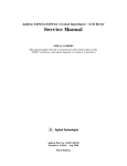
The minimum distance between inverter and surrounding walls or any other installed
apparatuses should be in accordance with Figure 3.1:
Figure 3.1 Minimum distance
No heating equipment in close of the inverter
The inverter must be intalled vertically, so the power block could be naturally
ventilated
Provide forced ventilation, if 45 ̊C in the cabinet are exceeded.
3.1
Running in exploitation
WARNING
The device carries lethal grid voltages.
For safe operation it is necessary to observe the following rules:
The device must only be installed, operated and maintained by qualified personnel.
To comply with the declared value of the supply voltage, both the inverter and the
controlled motor.
The recommended main circuit breaker can not be strengthened or replaced with
more powerful.
After switching off the supply voltage you must wait minimum 10 minutes, before
starting assembly or disassembly the power output terminals.
Manual ELDI (Revision NEW)
6/33
IUM ELDI ENG V1.00 0415
Copyright ELECTROINVENT
The inverter has built-in electronic protections that stop the motor in case of emergency.
These situations may be caused both by mechanical issues with motor and by issues
associated with the supply grid.
The input supply voltage of the inverter must be disconnected before starting assembly or
disassembly the motor.
The products and materials presented in this document may be changed or modified at
any time, either from a technical point of veiw or in the way they operate. Their
description can in no way be considered contractual.
If the inverter is properly installed, maintained and operated as intended in accordance
with the requirements of the relevant product and correspond to the current instruction, it
complies with the requirements for electromagnetic compatibility and interference
immunity.
User is responsible for providing the conditions under which the final product will cover
those standards.
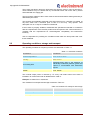
3.2
Operating conditions, storage and transport
The operating condition for frequency inverters are described in Table 3.1.
Table 3.1. Operating conditions
Parameters:
Condition:
Ambient temperature
from +5°С to +45°С
Humidity
80% at 30°С
Surrounding area
explosion-proof area in the absence of
electrically conductive particles, gases and
vapors in concentration with destructive
impact
Altitude
max. 3000м
The nominal output power is reduced by 1% every 100 meters when the inverter is
installed in an environment with an altitude above 1000 m.
Example: at 1500m Рout.= 0,95Рnom.
The conditions for transport and storage are listed in Table 3.2.
Table 3.2 Conditions for transport and storage
Parameters:
Condition:
Ambient temperature
from -20°С to +50°С
Humidity
80% at 30°С
Manual ELDI (Revision NEW)
7/33
IUM ELDI ENG V1.00 0415
Copyright ELECTROINVENT
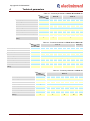
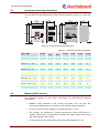
4
Technical parameters
Table 4.1. Technical parameters of ELDI / M and ELDI / A
Type
ELDI / M
Dimension
Rated output power
kW
Input voltage
VAC
Input frequency
Hz
Input current
A
Output voltage
VAC
Output frequency
Hz
Nominal output current
A
Current overload (max. for 60 sec.)
A
Dissipated power at nominal load
W
Маx impulse current when dinamic
braking
A
0,37
ELDI / A
0,55
0,75
0,55
0,75
1,1
1,5
2,2
13,5
18,0
7,1
10,1
85
110
200 ÷ 230 V1~ ± 10%
50 / 60 ± 5%
4,4
5,3
7,6
5,3
7,6
10,2
3 x 0…. Uin
0,5 ÷ 200 (option - 512)
2,2
3,0
4,3
3,0
4,3
5,9
150% IH once per 10 minutes
40
48
55
48
55
4
65
6
Table 4.2. Technical parameters of ELDI / B and ELDI / DF
Type
ELDI / B
ELDI / DF
Dimension
Rated output power
kW
Input voltage
VAC
Input frequency
Hz
Input current
A
0,55
0,75
1,1
1,5
2,2
3,0
4,0
5,5
7,5
11,0
16,0
21,5
31,8
12,5
16,0
22,0
180
270
450
380 ÷ 400 V3~ ± 10%
50 / 60 ± 5%
2,1
2,9
4,2
5,1
6,5
9,2
12,5
Output voltage
VAC
3 x 0…. Uin
Output frequency
Hz
0,5 ÷ 200 (option - 512)
Nominal output current
A
Current overload (max. for 60 sec.)
A
Dissipated power at nominal load
W
Маx impulse current when dinamic
braking
A
2,0
2,3
3,2
4,2
6,0
7,6
10,2
150% IH once per 10 minutes
40
52
80
110
6
135
155
180
8
10
17
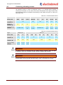
Table 4.3. Technical parameters of ELDI / D
Type
ELDI / D
Dimension
Rated output power
kW
Input voltage
VAC
Input frequency
Hz
Input current
A
Output voltage
VAC
Output frequency
Hz
Nominal output current
A
Current overload (max. for 60 sec.)
A
Dissipated power at nominal load
W
Маx impulse current when dinamic
braking
A
Manual ELDI (Revision NEW)
15
18,5
22
30
37
45
55
75
112
125
175
105
138
1300
1500
380 ÷ 400 V3~ ± 10%
50 / 60 ± 5%
42,9
52,9
62
82
94
3 x 0…. Uin
0,5 ÷ 200 (option - 512)
29
36
42
62
72
85
150% IH once per 10 minutes
550
680
17
8/33
720
840
920
40
1100
60
100
IUM ELDI ENG V1.00 0415
Copyright ELECTROINVENT
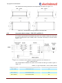
4.1
Overall and mounting dimensions
The overall and mounting dimensions of the inverters are shown on Figure 4.1 and Table
4.4.
Table 4.1. Overall and mounting dimensions
Table 4.4. Overall and mounting dimensions
H, mm
Wmax,
mm
Dmax,
mm
C, mm
h, mm
w, mm
d, mm
ELDI M / 0,37 - 0,75
160
86
103
140
150
72
5
ELDI A / 0,5 - 0,75
210
130
105
180
195
105
6
ELDI A / 1,1 – 2,2
210
130
140
180
195
105
6
ELDI B / 0,5 – 1,1
210
130
105
180
195
105
6
ELDI B / 1,5 – 2,2
210
130
140
180
195
105
6
ELDI B / 3,0
245
130
140
215
230
105
6
ELDI B / 4,0 – 5,5
280
130
140
250
265
105
6
ELDI DF / 7,5 – 11,0
340
175
186
300
320
140
7
ELDI D / 15,0
310
210
180
285
295
180
7
ELDI D / 18,5 – 30,0
410
275
250
370
390
235
9
ELDI D / 37,0 – 75,0
655
315
270
580
620
263
13
Type /, kW
4.2
Mounting ELDI inverter
For trouble-free operation of the inverter is necessary to comply with the following
requirements:
Between output terminals of the inverter and motor must not have any
commutation apparatuses as contactors, circuit breakers, relays, and more!
Do not connect the supply voltage to the output terminals U, V, W !
The inverters are intended for 3-phase asynchronous motors connected in a
scheme, where there is correspondence between the supply voltage of the motor
and output voltage of the inverter!
Do not connect the zero phase of the grid to the output terminals U, V, W !
Manual ELDI (Revision NEW)
9/33
IUM ELDI ENG V1.00 0415
Copyright ELECTROINVENT
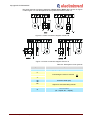
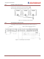
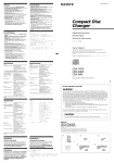
The power terminal connection diagrams of ELDI / M and ELDI / A are shown on Figure
4.2 and Figure 4.3. The descriptions of the symbols are listed in Table 4.5.
Figure 4.2. Power connection diagram of ELDI / M
Figure 4.3. Power connection diagram of ELDI / A
Table 4.5. Descriptions of the symbols
Symbol:
Description:
L1, L2
Supply voltage 200-230 VAC / 50-60 Hz
U
V
Connecting the motor in scheme
W
Protective Earth (PE)
Rb
Output for external braking resistor
Rb
Circuit breaker
(Q – tripolar; Q1 – dipolar)
Q
Manual ELDI (Revision NEW)
10/33
IUM ELDI ENG V1.00 0415
Copyright ELECTROINVENT
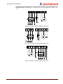
On Figure 4.4, Figure 4.5 и Figure 4.6 are shown the power connection diagrams of
ELDI/B, ELDI/DF and ELDI/D. The descriptions of the used symbols are listed in Table
4.6.
Figure 4.4. Power connection diagram of ELDI / B
Figure 4.5. Power connection diagram of ELDI / DF
Figure 4.6. Power connection diagram of ELDI / D
Manual ELDI (Revision NEW)
11/33
IUM ELDI ENG V1.00 0415
Copyright ELECTROINVENT
Table 4.6. Descriptions of the symbols
Symbol:
Description:
U
V
Motor terminals
W
Rb
Output for external braking resistor
Rb
L1
Supply voltage 3х380-400 VAC / 50-60Hz
L2
L3
N
Operating zero
Protective Earth (PE)
Q
Circuit breaker
+, -
Polarity of the capacitor battery
When performing wiring diagrams of the power terminal, the requirements for section of
the connecting wires must be observed. In Table 4.7-1 and Table 4.7-2 you can find the
recommended sections of the connecting wires where the line length is not greater than
10 m, and also the values of the input circuit breaker.
Table 4.7-1. Recommended sections of the connecting wires
ELDI / M и ELDI / A
ELDI / B
0,37-0,55
0,75
1,1-2,2
0,55-0,75
1,1
1,5
2,2
3,0-5,5
1,0
1,5
2,5
1,0
1,0
1,5
1,5
2,5
Output, mm
(U, V, W, PE)
1,0
1,0
2,5
1,0
1,0
1,5
1,5
2,5
Input circuit
breaker QF, A
1,0
16
25
10
10
10
10
20
Power, kW
2
Input, mm
(L1, L2, L3, N, PE)
2
Table 4.7-2. Recommended sections of the connecting wires
ELDI / DF
ELDI / D
7,5
11
15
18,5
22
30
37
45
55
75
4,0
4,0
6,0
10
10
16
25
35
35
50
Output, mm
(U, V, W, PE)
4,0
4,0
6,0
10
10
16
25
35
35
50
Input circuit
breaker QF, A
25
40
50
63
100
100
125
125
125
160
Power, kW
2
Input, mm
(L1, L2, L3, N, PE)
2
Manual ELDI (Revision NEW)
12/33
IUM ELDI ENG V1.00 0415
Copyright ELECTROINVENT
4.3
Connecting of braking resistor
The braking resistor is used to extinguish energy. It is required during braking or
reversing the direction of the motor that drives mechanisms with large inertia mass.
Recommended values of resistance and capacity of the resistor are given in Table 4.8-1
and Table 4.8-2.
Table 4.8-1. Recommended values
Type
Power, kW
ELDI / A
0,55
Braking
resistor, Ω
0,75
ELDI / B
1,1-2,2
100
Power of
resistor, W
20
Type braking
resistor
FR-ABR-0,75K
25
0,55-0,75
1,1
700
350
30
FR-ABR2,2K
1,5
35
FR-ABRH0,75K
FR-ABR-H1,5K
2,2
3,0-4,0
5,5
100
150
110
50
50
50
FR-ABR
FR-ABR
FR-ABR
-H3,7K
-H5,5K
-H2,2K
Table 4.8-2. Recommended values
Type
ELDI / DF
ELDI / D
Power, kW
7,5
11
15
Braking
resistor, Ω
75
52
2x18
30
25
20
12
Power of
resistor, W
200
1500
1500
2500
5000
7500
10000
FR-ABR
FR-ABR
FR-ABR
-H7,5K
-H11K
-H15K
Type braking
resistor
18.5
22
30
37
45
55
75
WARNING
In braking mode on terminals Rb the voltage reaches 780Vdc. Must be taken
measures to ensure the necessary clearances when installing the resistors.
WARNING
Input terminals Rb is not protected against short circuits. When there is a short circuit,
terminals Rb or touching a bare wire to housing or land, can damage the inverter.
Manual ELDI (Revision NEW)
13/33
IUM ELDI ENG V1.00 0415
Copyright ELECTROINVENT
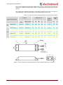
The technical parameters of braking resistors are shown in Table 4.9 (for inverters with
power from 0.55kW to 7.5kW) and in Table 4.10 (for inverters with power from 11kW to
15 kW).
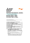
The overall and mounting dimensions of the braking resistors are shown on Figure 4.7
(corresponding to Table 4.9) and FIgure 4.8 (corresponding to Table 4.10).
Table 4.9. The overall and mounting dimensions of the braking resistors
Invenrter
Dimension, mm
Braking
resistor, Ω
Type of braking resistor
Power,
kW
Supply voltage
W
W1
W2
D
H
Crimping
terminal,
mm
B
d
FR-ABR-0,75K
0,55 - 0,75
220 VAC
215
200
175
40
21
100
7,0
4,3
FR-ABR-2,2K*
1,1 - 2,2
220 VAC
240
225
200
50
26
60
7,0
4,3
FR-ABR-H0,75K
0,55 - 0,75
3x380-400 VAC
140
125
100
40
21
700
7,0
4,3
FR-ABR-H1,5K
1,1 – 1,5
3x380-400 VAC
215
200
175
40
21
350
7,0
4,3
FR-ABR-H2,2K
2,2
3x380-400 VAC
240
225
200
50
26
250
7,0
4,3
FR-ABR-H3,7K
3,7 (4,0)
3x380-400 VAC
215
200
175
61
33
150
7,0
4,3
FR-ABR-H5,5K
5,5
3x380-400 VAC
335
320
295
61
33
110
9,5
5,3
FR-ABR-H7,5K
7,5
3x380-400 VAC
400
385
360
80
40
75
9,5
5,3
200V
400V
Figure 4.7. The overall and mounting dimensions of the braking resistors from Table 4.9
Manual ELDI (Revision NEW)
14/33
IUM ELDI ENG V1.00 0415
Copyright ELECTROINVENT
Table 4.10. The overall and mounting dimensions of the braking resistors
Invenrter
Dimension mm
Braking
resistor, Ω
Type of braking resistor
Power,
kW
Supply voltage
W
W1
W2
Crimping
terminal,
mm
d
FR-ABR-H11K
11
3x380-400 VAC
400
385
360
52
6,4
FR-ABR- H15K *
15
3x380-400 VAC
300
285
260
2 x 18
8,4
400V
* For H15K, you must connect the two resistors (18Ω) consecutively.
Figure 4.8. The overall and mounting dimensions of the braking resistors from Table 4.10
4.3.1
Electromagnetic compatibility
The inverter must be installed, maintained, used and adjusts in accordance with this
instruction. To achieve compliance with the requirements for electromagnetic
compatibility is necessary strict adherence to recommendations for installation and
operating reliability below:
Use shielded power cables, connecting the inverter with the motor and the inverter
with the braking resistor (where available);
Grounding of the shielded cable should be on a common screw marked with PE near
to inverter;
The cables must be grounded at both ends;
Installation of input filter to inverter;
Installation of the inverter and the equipment in a metal cabinet;
Manual ELDI (Revision NEW)
15/33
IUM ELDI ENG V1.00 0415
Copyright ELECTROINVENT
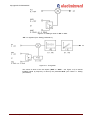
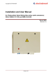
Figure 4.9. Mounting connection diagram for inverter with power 0,55kW to 5,5kW
(four core scheme)
1.
Ground plate;
2.
ELDI inverter;
3.
Ungrounded power cables;
4.
Ungrounded conductors for output relay contacts of the inverter;
5.
A shielded wire for connecting the output of the inverter with the motor. The shielding
is grounded at both ends. The shielding must not be interrupted, and if there are
intermediate terminals, they must be grounded in metal boxes.
6.
Shielded cable for management and control. For applications that require a large
2
number of conductors must be used such with small cross-section (0,5 mm ). The
shielding is grounded at both ends. The shielding must not be interrupted, and if
there are intermediate terminals, they must be grounded in metal boxes.
7.
A shielded cable to connect the braking resistor, if it is used. The shielding is
grounded at both ends. The shielding must not be interrupted, and if there are
intermediate terminals, they must be grounded in metal boxes.
Manual ELDI (Revision NEW)
16/33
IUM ELDI ENG V1.00 0415
Copyright ELECTROINVENT
8.
9.
The attachment and connection to ground of the shielding of the conductors 6, 7 and
8 are made as close as possible to the inverter as follows:
-
remove the isolation
-
use stainless steel brackets with suitable size for the places from which it was
removed the isolation of the wires and attach them to the grounding plate 1. The
bracket must be fixed to the plate strong enough to get a good contact.
Grounding screw.
10. Input filter connected directly to the power supply with unshielded wire.
Note: Although there is grounding between the inverter, motor and shielding of the wire it
is necessary to connect the protective cables PE (green-yellow) to the appropriate
terminals on each device.
4.3.2
Connection block scheme – ELDI/B
The connection block scheme of the inverter ELDI/B with power from 0,55kW to 5,5kW
when using input filter is shown in Figure 4.10.
Figure 4.10. Connection block scheme of inverter type ELDI / B – from 0,55 to 5,5 kW
The types of input filter are shown in Table 4.11.
Table 4.11. Type of input filter - from 0,55 to 5,5 kW
Type of filter
Power of the inverter, kW
3MF-400/8
from 0,55 to 3,0
3MF-400/16
from 4,0 to 5,5
Manual ELDI (Revision NEW)
17/33
IUM ELDI ENG V1.00 0415
Copyright ELECTROINVENT
The overall and mounting dimensions of the input filter are shown on FIgure 4.11:
3MF – 400/8
3MF – 400/16
Figure 4.11. Overall and mounting dimension of the input filter
4.3.3
Connection block scheme – ELDI / DF and ELDI / D
For inverters type ELDI/DF and ELDI/D with power from 7,5kW to 55kW we recommend
the use of three-phase input (GRID) choke connected according the scheme below
(Figure 4.12):
Figure 4.12. Connection block scheme of inverters type ELDI / DF and ELDI / D –
from 7,5 kW to 55 kW
The correspondence between the power of the inverter and the type of filter is given in
Table 4.12.
Table 4.12. Type of input filter – from 7,5 kW to 55 kW
Type of filter
Power of the inverter, kW
Inductance, mH
РК - 1035
from 7,5 to 11,0
1,5
РК – 0560
from 15,0 to 22,0
0,5
РК – 02113
from 30,0 to 37,0
0,2
РК – 02116
from 45,0 to 55,0
0,2
Manual ELDI (Revision NEW)
18/33
IUM ELDI ENG V1.00 0415
Copyright ELECTROINVENT
4.3.4
Protective earth of the inverter
Protective earth is performed on terminals marked PE or
Way of grounding of several inverters is shown in Figure 4.13.
Figure 4.13. Grounding of several inverters
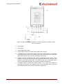
4.3.5
Connecting the control terminal
Connecting the control terminal for inverters type ELDI is shown on Figure 4.14.
ELDI / M
ELDI / A, ELDI / B, ELDI / DF, ELDI / D
Figure 4.14. Connecting the control terminal
Manual ELDI (Revision NEW)
19/33
IUM ELDI ENG V1.00 0415
Copyright ELECTROINVENT
4.4
Input - Output interface description
4.4.1
Digital inputs
ON
When submitting a + 24V at input ON (for ELDI / M + 15V) starts the converter, ie
gives him a work permit. This is only possible when in option "Int" is selected "IO"
control of the inverter from external signals - through input output interface (when in
option "Int" is selected "UI" converter is controled from the keyboard). If in option
“Int” there is another parameter the submission of input voltage will have no result!
The engine speed will depend on the voltage of the analog inputs described below
and appropriate settings in “LSP” and “HSP”.
F/R
When the signal is 0 V (or if admission is free), the motor rotates in one direction.
When on this input submit a signal of +24 V (for ELDI / M + 15V), the direction of
rotation of the motor turns.
DI1
Програмируем input - When submitting a +24V (for ELDI/M +15V), the motor
accelerates to the speed specified by parameter "P1F" with direction set by
parameter "P1d". Acceleration / braking depend on the setting of parameters
“Acc/dcc”.
DI2
Програмируем input - When submitting a +24V (за ELDI/M +15V), the motor
accelerates to the speed specified by parameter “P2F” with direction set by
parameter “P2d”. Acceleration / braking depend on the setting of parameters
“Acc/dcc”.
“DI1” and “DI2” also require in option "Int" to be selected "IO" control of input output
interface in other words terminal block of the inverter.
NOTICE
At the same time activating the input "ON" and "DI1" or "DI2" the inverter is settled in
position Rdy!
NOTICE
When the converter is operated by input-output interface provided time to work is
limited by the timer. The timer setting may be different when you activate the
transmitter of "ON" or by "DI" input. In the menu with the parameters the function "tIO"
determines which timer is adjusted. Whether the timer is active or not shall be
determined in “tAI”. Time in sec. is adjusted in “tI”. If the timer is used after the time
expires comes out error message “tout”. Any meanwhile stopping of the inverter
resets the timers!
Manual ELDI (Revision NEW)
20/33
IUM ELDI ENG V1.00 0415
Copyright ELECTROINVENT
4.4.2
4.4.3
Digital outputs
FL1,
FL2
Normally closed relay contact with parameters 0,1 A/220VAC (1А/30VDC). When
the inverter is powered up and there is no displayed protection - the contact of the
relay is closed! The opening of the contact means that any of the protections is
activated or an error occurs. In the absence of the supply voltage relay contact is
open.
DО1,
DО2
Normally open relay contact with parameters 0,1A/220VAC (1А/30VDC). The
contact closure of the relay can be configured via parameter “do2” (see Table 6.1.
Setting parameters) for the following functions:
“Srr” - when reaching the frequency of the assignment (±2,5Hz hysteresis);
“Ftc” - when reaching the predetermined in the parameter "FtA" frequency;
Analog outputs
AО1,
AО2
4.4.4
Those two analogue outputs (0/4-20mA) can be configured via parameters “Ao1”
and “Ao2” for the following functions:
“Sur” - the corresponded output signal is proportional to the inverter output
frequency;
“SLc” - the corresponded output signal is proportional to the inverter output phase
current;
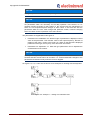
Analog inputs
The choice of input for setting speed is determined
parameter “Acr” (see Figure 4.15, Figure 4.16, Figure 4.17).
AI1
AI2V
AI2C
by
the
state
of
0 - 10V - Speed reference. By changing the voltage level it changes the output
frequency (i.e., motor speed) in the range “LSP” “HSP”.
0 - 10V Speed reference.
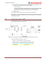
4 - 20mA Speed reference.
Analog inputs colud be assigned through the parameter “Acr”. Input structures are:
“rEF”: Control of the output frequency (motor speed) by changing the level of “AI1” (see
Table 6.1. Setting parameters).
Figure 4.15. Control of the output frequency
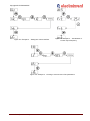
“Sri”: Adding a value of “AI2” to “AI1” (see “Setting parameters”).
Manual ELDI (Revision NEW)
21/33
IUM ELDI ENG V1.00 0415
Copyright ELECTROINVENT
Figure 4.16. Adding a value of “AI2” to “AI1”
“PiF”: PI regulator (see “Setting parameters”).
Figure 4.17. PI regulator
The choice of which of the two inputs ("AI2V" or "AI2C" - see Figure 4.14) to submit
feedback signal by frequency is done by the parameter“AcU” (see Table 6.1. Setting
parameters).
Manual ELDI (Revision NEW)
22/33
IUM ELDI ENG V1.00 0415
Copyright ELECTROINVENT
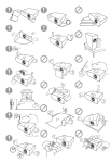
5
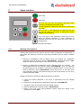
Users interface
motor start
motor stop
when you are in the menu of parameters the button enters
correcting (visualization) parameter mode.
In mode adjustment of parameter with this key confirms the
new value.
when you are in mode adjustment of parameter with this
key you can return to the menu of parameters without
saving the current setting
in the main menu of the parameters, these keys serve to
select the desired parameter. In mode adjustment of
parameter with them you can change the current value of
the parameter.
Figure 5.1. Keyboard description
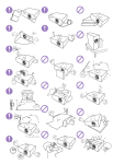
5.1.1
Working with keyboard
Working with keyboard can be split into two main modes visualization and adjustment. In
both modes the movement in the main menu with parameters going on with the “arrow”
buttons.
1. Entering in visualization mode it happens when you reaching the visualization
parameter and then press the button “DATA/ENTER”. Pressing tha button “ESC”
leads to exit this mode and return to the main menu with parameters.
2. Entering in adjustment of parameter mode it happens when you reaching
the
desired parameter and then press the button “DATA/ENTER”. Once you are inside
the parameters you can change the value with the “arrow“ buttons. To save the new
value is sufficient to press “DATA/ENTER”, which will return us to the main menu
with parameters. Cancel or exit without saving the value of parameter you can do by
pressing the button “ESC”.
Setting a parameter is done by the following sequence of actions:
a. Finding the desired parameter in the menu of parameters using the “arrow”
buttons.
b. Entering in mode adjustment of parameter using button “DATA/ENTER”.
c. Change the value of parameter using the “arrow” buttons.
d. Save the parameter by pressing a button “DATA/ENTER”.
e. Return to the main menu with parameters without saving the change of the
parameter by button “ESC”.
Manual ELDI (Revision NEW)
23/33
IUM ELDI ENG V1.00 0415
Copyright ELECTROINVENT
NOTICE
Saving the parameters becomes after pressing the button “DATA/ENTER”.
NOTICE
The parameters of the inverter are organized into two levels of access. In the first level
are parameters which are necessary for the daily operation of the device, ie it is
required frequent changes of their values. In the second level are parameters for
which it is not required frequent changes of their values. In this level are also the
parameters which the user must change with particular caution, because changing
them can cause incorrect operation of the entire device.
The parameters are sepparated in two types of:
Parameters for visualization “В”. With this type of parameters is displayed current
value of the parameter. This includes: value of the output frequency, direction of
rotation of the motor, current in the motor, etc. When on the terminal is displayed
parameter of this type, the keys up, down and enter are inactive.
Parameters for adjustment “Н”. With this type parameters can be adjusted the
characteristics of the inverter.
NOTICE
When you change the parameter values during operation of the motor it must be
ensured that this will not lead to an accident. It is recommended that changes to the
parameters must be done only when the motor is stopped.
On Figure 5.2, 5.3, 5.4 and 5.5 are shown some examples for working with the keyboard.
Figure 5.2. Example 1 – Setting of acceleration time
Manual ELDI (Revision NEW)
24/33
IUM ELDI ENG V1.00 0415
Copyright ELECTROINVENT
Figure 5.3. Example 2 - Setting the control interface
Figure 5.4. Example 3 - Visualization of
current output frequency
Figure 5.5. Example 4 - Passing to second level of the parameters
Manual ELDI (Revision NEW)
25/33
IUM ELDI ENG V1.00 0415
Copyright ELECTROINVENT
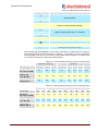
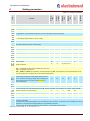
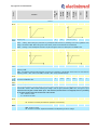
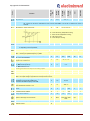
6
Setting parameters
Resolution
Unit
Maximum
value
Minimum
value
Function
Factory
settings
Parameter
type
Code
Table 6.1. Setting parameters
Level 1
Inverter state
- charging the capacitors
- catching spinning load
- stopped motor. A dash indicates the direction in which it will rotate the motor after startup
- spinning motor. A dash indicates the direction or the value of the selected from dSP menu parameter of the motor – n, F, I,
U – accordingly speed, frequency, current, voltage
- DC brake
If on the display is shown blinking or not described above symbolics, it means that an error occurred. For a description of
error codes, please see Table 7.1 and Table7.2.
Parameter to be displayed in rdy menu after starting
H
on
Output frequency reference at “Int”=”UI”
H
50
Rotating direction reference at “Int”=”UI”
H
F
Output frequency
Speed of rotation
-
-
Hz
-
-
-
B
Hz
-
B
rpm
-
Rotating direction
B
-
-
Motor current
B
A
-
Supply voltage
B
V
-
Active interface – determining how to start, stop, set the
speed and direction
H
-
-
UI
on, F, n, I, U
LSP
HSP
F, r
UI, IO, CbL, Pot
”UI” – START and STOP from the buttons, reference for output frequency by “FtS”, and rotating direction by “dtS”
“IO” – managed by the Input / Output interface see Figure 4.16
“Cbl” – managed by RS 485 port
“Pot” - START and STOP from the buttons, the rotating direction by “dtS”, output frequency from the potentiometer on the
front panel (valid only for models ELDI / M with external potentiometer)
Base inverter frequency.
The frequency at which the output voltage reaches the max
value = the value of the supply voltage. At 40 Hz setting will
follow a larger moment on the motor shaft at 40 Hz, but
more current at idle.
H
50
40
60
Hz
-
Time for acceleration
H
5,0
0,1*
3600
s
-
Time for deceleration
H
5,0
0,1*
3600
s
-
The time depends, also from additional paremter “rtP” located in “Level 2”. It is possible to use coasting, please see “Stt”.
Minimum value of the output frequency
H
0
0
HSP
Hz
-
Maximum value of the output frequency
H
50
LSP
200
Hz
-
Currnet limiting - low level
H
120
50
160
%In
-
Currnet limiting - high level
H
160
CLL
180
%In
-
Current limiting function prevents the current through the motor to exceed a specified level. This is done to protect the
inverter of overloading.
The low level of current limiting operates only in acceleration mode of the motor, ie if the motor current exceeds this level, the
acceleration of the motor will be stopped while the current falls below this level.
The high level of current limiting operates under acceleration, in fixed mode and when braking.
* Different for some models. M - 0,1; A, B, DF и D – 0,3.
Manual ELDI (Revision NEW)
26/33
IUM ELDI ENG V1.00 0415
Resolution
Unit
Maximum
value
Minimum
value
Function
Factory
settings
Parameter
type
Code
Copyright ELECTROINVENT
Critical frequency jump.
This parameter auto add / substract ± 2 Hz , when reaching the JPF value. This is done
to avoid operation of the motor at a speed at which the mechanical resonance occurs.
Когато този параметър има стойност нула, функцията е деактивирана.
Ниво на тока на DC спирачката
H
25
25
70
%In
0,1
Време за работа на DC спирачката
(само когато Fdc = Fin)
H
0
0
25
s
1
H
Fin
-
-
Frequency, by which is triggered the DC brake
H
0,0
0
HSP
Hz
0,1
“Boost” – boosting the amplitude of the output voltage =>
boosting the moment of the motor at low speed, but more
current of the motor at idle.
H
5
0
20
%Un
0,1
Level
H
0
0
20
%Un
0,1
Time
H
0
0
10
s
0,1
When this parameter is zero, the DC brake is disabled.
InF – after stopping the motor is established in mode DC
brake for time until the next startup. This means that the
initially supply of the motor will not be established at the
mode of the DC brake. Fin – the operating time on the DC
brake is determined by “tdc”.
Fin, InF
Level and time of the temporary boosting amplitude of the output voltage. When the time is zero, the "temporary boost" is
disabled.
Preset rotation speed, controlled by digital inputs activated by input terminal see Figure 4.14
DI 1:
Frequency
H
0
LSP
Direction
H
F
Frequency
H
0
Direction
H
F
Proportional gain
H
1
0,1
Integral gain
H
1
Feedback gain
H
1
Display the last falt occured
B
HSP
Hz
0,1
-
-
Hz
0,1
-
-
100
-
0,1
0,1
100
1/s
0,1
0,1
100
-
0,1
-
-
F, r
DI 2:
LSP
HSP
F, r
PI regulator configuratiing:
The errors descriptions are in Table 7.1 and Table 7.2
The errors participate as corresponding No in Table 7.1 and Table 7.2
“Level 2“ enter (see Figure 5.3)
Manual ELDI (Revision NEW)
H
27/33
no
YES, no
IUM ELDI ENG V1.00 0415
Unit
Resolution
Lin
Lin, Fcr
-
-
dcc, Inr1, Inr2
-
-
Maximum
value
H
Minimum
value
Factory
settings
Function
Parameter
type
Code
Copyright ELECTROINVENT
Level 2
Type of the U/F curve
Lin – linear,
Fcr - square
Stopping way
H
dcc
“dcc” – control stop in function of the time refered in the “dcc”.
“Inr1” – coasting. When setting this parameter any subsequent start becomes, by offsetting of the motor regardless of the
setting in the function “SPr”. Before using this function “Inr1”, please consult first with the manufacturer!
“Inr2” – coasting. In each subsequent start does not pass through the function for interception of rotatable motor.
Type of the acceleration (deceleration) function
H
Lin – linear,
Lin
Lin, Scr
-
-
Fn, FtS
-
-
Scr – S type,
Specifying the acceleration and deceleration time
H
Fn
“Fn” – the adjusted in Acc and dcc parameter is the time for acceleration or deceleration of the motor to or from its rated
frequency “FrS”.
“FtS” – the adjusted in Acc and dcc parameter is the time for acceleration or deceleration of the motor to or from reference
frequency (at “Int” = “UI” – this in menu “FtS”, or at “Int” = “IO” – set by external terminal).
Rated motor frequency
H
50
50
60
Hz
10 Hz
Reted motor speed (RPM). The correct setting depends on
the correct visualization “nrt”
H
1000
600
3000
rpm
1
Swithching frequency
H
4
2
12
kHz
1 kHz
Catch spinning motor
H
no
-
-
YES, no
Used in frequent failures of the line voltage if the motor rotates a large inertia mass. To operate the function, management
must be IO in function "Int" and after restoring the voltage it must be given permission (ON to 24V, see Figure 4.14). If
permission was not given, and the motor spins - after inclusion (and the motor is not stopped), there is a possibility
for an electric shock in the motor and burning of the inverter!
YES – function is active
no - function is not active
Automatic restart:
H
YES
YES, no
-
-
YES, no
-
-
YES - function is active
no - function is not active (see “Electronic protection of the inverter”)
Automatic deceleration:
H
YES
YES - function is active
no - function is not active. Adjust the deceleration time depending on the DC voltage.
Manual ELDI (Revision NEW)
28/33
IUM ELDI ENG V1.00 0415
YES, no
Resolution
Maximum
value
YES
Minimum
value
H
Unit
I2t protection:
Factory
settings
Function
Parameter
type
Code
Copyright ELECTROINVENT
-
-
YES - function is active
no - function is not active. Integrates the motor current when Iдвиг > In, and do not allowing the motor to
overheat.
I2t protection – motor cooling type:
H
C0
C0, C1, C2, C3
-
-
C0 – motor with strong independent cooling;
C1 - motor with low independent cooling;
C2 – self cooling motor;
C3 – motor with poor cooling;
Management of the fan:
H
On
On, t
-
-
H
Ftc
Srr, Ftc
-
-
on – it works at Run, DCBrake and Catch states;
t - depending on the temperature;
DO2 contacts closing (see Figure 4.14)
“Srr” – reaching the reference frequency. (“Int” = “UI” set in by parameter “FtS”, or “Int” = “IO” set by external terminal);
“Ftc” – reaching the specified frequency by “FtA”
Frequency at which DO2 will switch if it is configured as
Ftc, in the parameter do2.
H
45
Hz
0,1
H
rEF
rEF, Sri, PiF
-
-
H
U
C, U
-
-
AO1
H
Sur
Sur, SLc
-
-
AO2
H
Sur
Sur, SLc
-
-
H
On
On, dI1
-
-
H
no
YES, no
-
-
H
0
0
255
s
1
Individual network address
H
1
1
128
-
1
Group network address
H
129
129
255
-
1
Speed of exchange over the network
H
9600
75, 150, 300, 600,
1200, 2400, 4800,
9600
bps
-
Return to the factory settings values for all parameters
H
YES
YES, no
-
-
Software version
B
Assignment of the input structure in AI1 and AI2V(C) see
Figure 4.15, 4.16 and 4.17
Choosing the AI2 type:
C – AI2C current (4;20mA)
U – AI2V voltage (0;10V)
LSP
HSP
Choosing the value to be output on the analog outputs:
“Sur” - the output voltage is proportional to the output frequency;
“SLc” - the output voltage is proportional to the output motor current;
Choosing a timer for setting. Confirming one of the two
parameters we get access to tAi and ti.
Otherwise after tIO the display shows InA.
Adjustment the selected from the menu tIO – “ON” or “dI1”,
timer whether will be active or not.
Setting the time of the respective timer selected in tIO
menu.
Manual ELDI (Revision NEW)
29/33
IUM ELDI ENG V1.00 0415
Copyright ELECTROINVENT
7
Electronic protection of the inverter
The inverter has an integrated protections which protect itself and the connected motor:
Protection from over and under voltage;
Protection from overheating the inverter;
Protection from over load the motor - I2t protection;
Protection from short circuit on the motor terminals;
Protection from earth falt – output terminal shorted to input;
Protection from no conection in the current loop AI2C;
Protection from damage the memory, containing the parameters;
Protection from overcurrent the inverter;
Internal software errors;
The recovery after activating protection status "rdY" depends on the setting of parameter
"Art".
Built-in protections are two types: those that can recover automatically and those that
necessarily require external intervention.
These two groups are shown respectively Table 7.1 and Table 7.2.
NOTICE
Activating the Art function for automatic recovery for automatic reinstatement to work
after the occurrence of protection can lead to automatically startup of the inverter and
the associated motor.
Protections that can recover an infinite number of times in Аrt = YES:
No:
Protection:
-
0
USF – undervoltage
2
OLF – motor overload
-
3
OHF – overheat the
inverter
-
Manual ELDI (Revision NEW)
Table 7.1. Recover an infinite number of times in Art=YES
Probable cause:
Action:
mains supply voltage is
- check the mains voltage and the type
too low
of inverter
momentary drop in voltage
- reset the inverter
motor or load are too big
- check the type of the motor and load
bad adjustment of the I2t
- check the adjustments of I2t
protection
protection
poor cooling, a dusting
- Improve the cooling, provide additional
the cooling didn’t work
ventilation if necessary
30/33
IUM ELDI ENG V1.00 0415
Copyright ELECTROINVENT
Protections which are recovered at a limited number of times in Art = YES:
No:
1
Protection:
OSF – overvoltage
-
4
7
6
SC, SC1, HII – short
circuit
5
EF - eartth fault
8
E2 - parameter memory
lost
10
tout - expiration of the
time set in tAI
9
CLF – no conection in the
current loop AI2C
-
-
Table 7.2. Recovered at a limited number of times in Art=YES
Probable cause:
Action:
mains voltage is too low
- check the mains voltage and type of
mains disturbance
inverter
decelarating time is too
- increase the deceleration time, add
small. The motor got to big
external brake resistor if necessary
inertia
short circuit in the motor or
- check the motor windings and
at the outputs of the
connections
inverter
- check the adjustment of Acc, pbl of
fault in motor or error in
the inverter. There may be a dropped
the settings in of the
phase of the motor.
inverter
shorting output motor
- check the motor windings and
phase to input or PE
connections
- internal fault
- return the inverter for servicing / repair
- if it does not suit you, disable the
corresponding timer (see the
description of the input-output
interface).
- no conection in the current
loop AI2C
- check the AI2C loop
The restoration of readiness state (rdY) is done by turning off the power, waiting the
display to go off and then reconnect again. If the next time you start the inverter and
again is activated protection it is necessary to send the unit for repair.
Manual ELDI (Revision NEW)
31/33
IUM ELDI ENG V1.00 0415
Copyright ELECTROINVENT
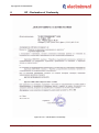
8
EC - Declaration of Conformity
Figure 8.1 EC – Declaration of Conformity
Manual ELDI (Revision NEW)
32/33
IUM ELDI ENG V1.00 0415
Copyright ELECTROINVENT
Contacts
Tel.:
+(359 2) 862 14 06; 868 70 65
43 „Cherni Vrah” blvd.
Fax:
+(359 2) 962 52 63
1407 Sofia, PO Box 74
E-Mail:
[email protected]
Bulgaria
Web site:
http://www.electroinvent.com/
Manual ELDI (Revision NEW)
33/33
IUM ELDI ENG V1.00 0415