1
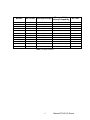
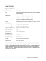
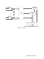
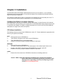
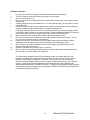
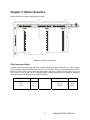
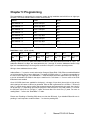
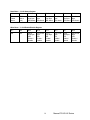
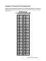
MODELS
PCI-IDI-XX SERIES
USER MANUAL
File: mpci-idi-xx.B1l
Notice
The information in this document is provided for reference only. Portwell does not assume any liability
arising out of the application or use of the information or products described herein. This document may
contain or reference information and products protected by copyrights or patents and does not convey
any license under the patent rights of Portwell, nor the rights of others.
IBM PC, PC/XT, and PC/AT are registered trademarks of the International Business Machines
Corporation.
Printed in USA. Copyright 2006 by Portwell I/O Products Inc. All rights reserved.
WARNING!!
ALWAYS CONNECT AND DISCONNECT YOUR FIELD CABLING WITH
THE COMPUTER POWER OFF. ALWAYS TURN COMPUTER POWER
OFF BEFORE INSTALLING A CARD. CONNECTING AND
DISCONNECTING CABLES, OR INSTALLING CARDS INTO A SYSTEM
WITH THE COMPUTER OR FIELD POWER ON MAY CAUSE DAMAGE
TO THE I/O CARD AND WILL VOID ALL WARRANTIES, IMPLIED OR
EXPRESSED.
2
Manual PCI-IDI-XX Series
Warranty
Prior to shipment, Portwell equipment is thoroughly inspected and tested to applicable specifications.
However, should equipment failure occur, Portwell assures its customers that prompt service and support
will be available. All equipment originally manufactured by Portwell which is found to be defective will be
repaired or replaced subject to the following considerations.
Terms and Conditions
If a unit is suspected of failure, contact Portwell' Customer Service department. Be prepared to give the
unit model number, serial number, and a description of the failure symptom(s). We may suggest some
simple tests to confirm the failure. We will assign a Return Material Authorization (RMA) number which
must appear on the outer label of the return package. All units/components should be properly packed for
handling and returned with freight prepaid to the Portwell designated Service Center, and will be returned
to the customer's/user's site freight prepaid and invoiced.
Coverage
First Three Years: Returned unit/part will be repaired and/or replaced at Portwell option with no charge for
labor or parts not excluded by warranty. Warranty commences with equipment shipment.
Following Years: Throughout your equipment's lifetime, Portwell stands ready to provide on-site or in-plant
service at reasonable rates similar to those of other manufacturers in the industry.
Equipment Not Manufactured by Portwell
Equipment provided but not manufactured by Portwell is warranted and will be repaired according to the
terms and conditions of the respective equipment manufacturer's warranty.
General
Under this Warranty, liability of Portwell is limited to replacing, repairing or issuing credit (at Portwell
discretion) for any products which are proved to be defective during the warranty period. In no case is Portwell
liable for consequential or special damage arriving from use or misuse of our product. The
customer is responsible for all charges caused by modifications or additions to Portwell equipment not
approved in writing by Portwell or, if in Portwell opinion the equipment has been subjected to abnormal
use. "Abnormal use" for purposes of this warranty is defined as any use to which the equipment is
exposed other than that use specified or intended as evidenced by purchase or sales representation.
Other than the above, no other warranty, expressed or implied, shall apply to any and all such equipment
furnished or sold by Portwell.
3
Manual PCI-IDI-XX Series
Table of Contents
Chapter 1: Introduction................................................................................................. 5
Table 1-1: Model Versions ....................................................................................... 6
Specification .............................................................................................................. 7
Figure 1-1: Block Diagram ...................................................................................... 8
Chapter 2: Installation................................................................................................... 9
Chapter 3: Option Selection ....................................................................................... 11
Figure 3-1: Option Selection Map.......................................................................... 11
Chapter 4: Address Selection .................................................................................... 12
Chapter 5: Programming ............................................................................................ 13
Chapter 6: Connector Pin Assignments.................................................................... 15
4
Manual PCI-IDI-XX Series
Chapter 1: Introduction
Features
•
•
•
•
•
Individually-Isolated AC/DC Inputs for up to Three 16-Bit Groups, 48 total.
Reverse Polarity protection
AC Filtering
Optical Isolation, Channel-to-Channel and Channel-to-Host PC.
Change-of-State detection (certain models).
Description
This series of cards provide as many as 48 optically-isolated inputs for AC/DC signals with Change-ofState (COS) Detection capability. Each input is reverse polarity protected and rectified by photo-coupler
diodes. Standard 12/24 AC control transformer outputs can be accepted as well as DC voltages. The
input range is up to 60VDC or AC Rms at frequencies of 40 to 10kHz.
Each input circuit contains a switchable filter that has a 4.7 millisecond time constant (without filtering, the
response is less than 30 microseconds). The filter must be selected for AC inputs in order to eliminate the
on/off response to AC. The filter is also valuable for use with slow DC input signals in a noisy
environment. The filter may be switched out for DC inputs in order to obtain faster response. Filters are
individually selected by jumpers. See Figures 1-1 and 3-1 for jumper arrangements.
The Change-of-State (COS) Detection capability (denoted by a “C” after the model number) provides a
means to automatically interrupt the host computer in real time. When one or more input bits change
state, a PCI interrupt is generated. That interrupt, in turn, can be used by your application program to
initiate a poll of the inputs, then signal appropriate alarms, and/or initiate scan of other I/O points that
have not been previously activated. This can greatly simplify your application program and eliminate need
to continuously poll inputs. Chapter 5 describes the programming aspects of the COS feature.
These cards provide a much lower cost per point than externally-mounted, optically-isolated, solid-state
modules or PLCs. Input connections are via ribbon-cable headers on the card, and a tie-down bar is
included to provide strain relief for those cables.
These cards are especially useful in applications where high-common-mode external voltages are
present as found in factory automation, energy management, security systems, and process monitoring
applications. In addition to protecting your computer from accidental contact with high external
voltages, the isolation provided eliminates troublesome ground loops.
There are 48-bit, 32-bit, and 16-bit versions. The latter two models are de-populated versions of the
48-bit card. Further, letters are appended to the model numbers to signify options included on the
card. Refer to Table 1-1 for model specific information.
5
Manual PCI-IDI-XX Series
MODEL
16A
16AC
32A
32AC
48A
48AC
16B
16BC
32B
32BC
48B
48BC
No. of Bits Max Input Voltage
16
16
32
32
48
48
16
16
32
32
48
48
Change-of State
Interrupt Capability
AC Filter
No
Yes
No
Yes
No
Yes
No
Yes
No
Yes
No
Yes
Yes
Yes
Yes
Yes
Yes
Yes
Yes
Yes
Yes
Yes
Yes
Yes
31V
31V
31V
31V
31V
31V
60V
60V
60V
60V
60V
60V
Table 1-1: Model Versions
6
Manual PCI-IDI-XX Series
Specification
Digital Isolated Inputs
Number of inputs:
16, 32, or 48
Type:
Non-polarized, optically isolated from each other and from the computer
(CMOS compatible)
Voltage Range
xxA:
Logic Low: 0 to 1.5VDC or AC Rms (40 to 10kHz)
Logic High: 3 to 31VDC or AC Rms (40 to 10kHz)
xxB:
Logic Low: 0 to 5VDC or AC Rms (40 to 10kHz)
Logic High: 11 to 60VDC or AC Rms (40 to 10kHz)
Isolation:
Optically Isolated channel-to-ground and channel-to channel * see note
Input Resistance
xxA:
1.8K ohms in series with optocoupler
xxB:
15K ohms in series with optocoupler
Non-Filter Response Times:
Rise Time = 10 uS / Fall Time = 30 uS
Filter Time Constant:
4.7ms
Power Required:
+5VDC @ 300mA typical
Environmental
Operating Temperature:
0EC to 70EC
Storage Temperature:
-55EC to +150EC
Humidity:
5% to 95% RH, without condensation
Board Dimension:
6.875" (174.6mm) long
**Note on Isolation: Opto-Isolators and connectors are rated for at least 500V, but isolation voltage
breakdowns will vary and is affected by factors like cabling, spacing of pins, spacing between traces on
the PCB, humidity, dust and other environmental factors. This is a safety issue so a careful approach is
required. For CE certification, isolation was specified at 60V DC or AC rms. The design intention was to
eliminate the influence of common mode. Use proper wiring techniques to minimize voltage between
channels and to ground. Tolerance of higher isolation voltage can be obtained on request by applying a
conformal coating to the board.
7
Manual PCI-IDI-XX Series
ISOLATED
INPUT 0
CURRENT
LIMITER
CHANGE-OFSTATE
DETECT
Vcc
JUMPER
SELECTABLE
FILTER
IRQ EN
INPUT
INPUTS 0-47
CURRENT
LIMITER
ISOLATED
INPUT 47
ADDRESS AND
CONTROL
LOGIC
REGISTERS
Vcc
JUMPER
SELECTABLE
FILTER
IRQ
PCI BUS INTERFACE
COMPUTER PCI BUS
Figure 1-1: Block Diagram
8
Manual PCI-IDI-XX Series
Chapter 2: Installation
A printed Quick-Start Guide (QSG) is packed with the card for your convenience. If you’ve already
performed the steps from the QSG, you may find this chapter to be redundant and may skip forward to
begin developing your application.
The software provided with this card is on CD and must be installed onto your hard disk prior to use. To
do this, perform the following steps as appropriate for your operating system.
Configure Card Options via Jumper Selection
Before installing the card into your computer, carefully read Chapter 3: Option Selection of this manual,
then configure the card according to your requirements. Our Windows based setup program can be used
in conjunction with Chapter 3 to assist in configuring jumpers on the card, as well as provide additional
descriptions for usage of the various card options.
CD Software Installation
The following instructions assume the CD-ROM drive is drive “D”. Please substitute the appropriate drive
letter for your system as necessary.
DOS
1.
2.
3.
4.
Place the CD into your CD-ROM drive.
Type B- to change the active drive to the CD-ROM drive.
Type GLQR?JJ- to run the install program.
Follow the on-screen prompts to install the software for this board.
WINDOWS
1.
Place the CD into your CD-ROM drive.
2.
The system should automatically run the install program. If the install program does not run
promptly, click START | RUN and type BGLQR?JJ, click OK or press -.
3.
Follow the on-screen prompts to install the software for this board.
LINUX
1.
Please refer to linux.html on the CD-ROM for information on installing under linux.
Caution! * ESD A single static discharge can damage your card and cause premature
failure! Please follow all reasonable precautions to prevent a static
discharge such as grounding yourself by touching any grounded
surface prior to touching the card.
9
Manual PCI-IDI-XX Series
Hardware Installation
1.
2.
3.
4.
5.
6.
7.
8.
9.
10.
11.
12.
13.
Do not install card into the computer until the software has been fully installed.
Turn OFF computer power AND unplug AC power from the system.
Remove the computer cover.
Remove the two (2) nuts retaining the strain relief brackets from the card, set one bracket aside
with the nuts.
Carefully install the card in an available 5V or 3.3V PCI expansion slot (you may need to remove
a backplate first).
Inspect for proper fit of the card and tighten screws. Make sure that the card mounting bracket is
properly screwed into place and that there is a positive chassis ground.
Feed ribbon cable(s) through the cutout in the mounting bracket one at a time and plug onto the
card header, starting closest to the mounting bracket. When all cables are installed, re-install the
strain relief bracket and nuts, and tighten until snug. DO NOT OVERTIGHTEN!
Make connections from installed ribbon cables to the field equipment / wiring.
Check all connections and installations to ensure the system is ready to be turned on. Do not
turn on field power before turning on the computer.
Replace the computer cover and turn ON the computer which should auto-detect the card
(depending on the operating system) and automatically finish installing the drivers.
Run PCIfind.exe to complete installing the card into the registry (for Windows only) and to
determine the assigned resources.
External / field power may now be turned on if desired.
Run one of the provided sample programs that was copied to the newly created card directory
(from the CD) to test and validate your installation.
The base address assigned by BIOS or the operating system can change each time new
hardware is installed into or removed from the computer. Please recheck PCIFind or Device
Manager if the hardware configuration is changed. Software you write can automatically
determine the base address of the card using a variety of methods depending on the operating
system. In DOS, the PCI\SOURCE directory shows the BIOS calls used to determine the
address and IRQ assigned to installed PCI devices. In Windows, the Windows sample programs
demonstrate querying the registry entries (created by PCIFind and NTIOPCI.SYS during boot-up)
to determine this same information.
10
Manual PCI-IDI-XX Series
Chapter 3: Option Selection
Each channel has a jumper configurable filter option.
NO FILTER
FILTER
3.90"
FLT47
FLT31
FLT32
FLT16
FLT 0
FLT15
6.90"
Figure 3-1: Option Selection Map
Filter Response Switch
Jumpers are used to select input filtering on a channel-by-channel basis (see Figure 3-1). When jumper
FLT0 is installed, filtering is introduced for input bit 0, FLT1 for bit 1, and so on. The tables below describe
filtering for Port 0. Ports 1 and 2 follow the same pattern with Port 1 having FLT16-31 (Bits 16-31) and
Port 2 having FLT32-47 (Bits 32-47). Filtering provides a slower response for DC signals as described
previously and must be used when AC inputs are applied.
JUMPER SELECTION
Bit Filtered
JUMPER SELECTION
Bit Filtered
FLT-0
FLT-1
FLT-2
...
Bit 0
Bit 1
Bit 2
...
FLT-8
FLT-9
FLT-10
...
Bit 8
Bit 9
Bit 10
...
11
Manual PCI-IDI-XX Series
Chapter 4: Address Selection
This card uses I/O addresses offset from the base address assigned by the PCI bus. The address spaces
are defined in the Programming section of this manual.
PCI architecture is Plug-and-Play. This means that the BIOS or Operating System determines the
resources assigned to PCI cards rather than the user selecting these resources with switches or jumpers.
As a result, you cannot set or change the card’s base address or IRQ level. You can only determine what
the system has assigned.
To determine the base address that has been assigned, run the PCIFind utility program. This utility will
display a list of all the cards detected on the PCI bus, the addresses assigned to each function on each of
the cards, and the respective IRQs.
Alternatively, Windows systems can be queried to determine which resources were assigned. In these
operating systems, you can use either PCIFind, or the Device Manager utility from the System Properties
applet of the control panel. The card is installed in the Data Acquisition class of the Device Manager list.
Selecting the card, clicking Properties, and then selecting the Resources Tab will display a list of the
resources allocated to the card.
The PCI bus supports 64K of I/O address space, so your card’s addresses may be located anywhere in
the 0000h to FFFFh range. The card occupies eight consecutive 8 bit registers in the I/O address space.
PCIFind uses the Vendor ID and Device ID to search for your card, then reads the base address and
IRQ. If you want to determine the base address and IRQ without using PCIFind, use the following
information:
The Vendor ID code is 494F (ASCII for “I/O”)
The Device ID code for the card is 0920
An example of how to locate PCI card resources is provided in the PCI/SOURCE directory, under your
installation directory. This code runs in DOS, and uses the PCI defined interrupt BIOS calls to query the
PCI bus for card-specific information. You will need the Device ID and Vendor ID listed above to use this
code.
12
Manual PCI-IDI-XX Series
Chapter 5: Programming
The base address is assigned by the computer system during installation and will fall on an eight byte
boundary. The card’s read and write functions are as follows:
Address
Read
Write
Base Address + 0
Port 0 Low Byte
N/A
Base Address + 1
Port 0 High Byte
N/A
Base Address + 2
Port 1 Low Byte
N/A
Base Address + 3
N/A
N/A
Base Address + 4
Port 1 High Byte
N/A
Base Address + 5
Port 2 Low Byte
N/A
Base Address + 6
Port 2 High Byte
N/A
Base Address + 7
IRQ Status Register/IRQ Clear
IRQ Enable/Disable
Note: Base + 7 only applies to COS (“C”) boards
Read Base + 0 (+1, +2, +4, +5, +6)
Bit 7
Bit 6
Bit 5
Bit 4
Bit 3
Bit 2
Bit 1
Bit 0
D7 of input
data
D6 of input
data
D5 of input
data
D4 of input
data
D3 of input
data
D2 of input
data
D1 of input
data
D0 of input
data
Reading a byte from the Port Data Base Address reads the 8 bits associated with that half of a port. The
Addresses labeled “Low Byte” are associated with pins 1 through 25, and the Addresses labeled “High
Byte” are associated with pin 26 through 50, as shown in Chapter 6, connector pin assignments.
Writing to these addresses has no effect.
Address Base + 7 is used to control and monitor Change-of-State IRQs. COS IRQs are enabled/disabled
on 8 bit boundaries (Port’s Low or High byte). To enable COS IRQs, write a “1” to the bit corresponding to
the Port’s Low or High byte. The “Write Base + 7” table describes which bits enable each byte. Writing “0”
to the bit will disable COS IRQs for that byte. A read from bit 7 will show a “1” if one or more of the COS
IRQs have been enabled.
Once COS IRQs have been enabled for the byte(s), a change of input level (low-to-high or high-to-low)
within that byte will cause an IRQ to be generated. After an IRQ is generated, bit 6 of Base + 7 will be set
Low (“0”), which can be used to confirm that a shared interrupt was generated by this card. Also, bits 0-5
will be set High (“1”) depending upon which byte(s) the COS occurred on. Any read of Base + 7 will clear
the IRQ latch, return bit 6 to it’s High (“1”) state, and return bits 0-5 to their Low (“0”) state. For more on
reading Base + 7 refer to the “Read Base + 7” table.
Please note: Enabling or Disabling IRQs does not clear the IRQ latch. If you disable IRQs while one is
pending, it is still required to read from Base + 7 to clear the pending IRQ.
13
Manual PCI-IDI-XX Series
Read Base + 7: COS Status Register
Bit 7
Bit 6
Bit 5
Bit 4
Bit 3
Bit 2
Bit 1
Bit 0
IRQ
Enable
Status
IRQ Status
(Active
Low)
Port 2
High Byte
IRQ Status
Port 2 Low
Byte
IRQ Status
Port 1
High Byte
IRQ Status
Port 1 Low
Byte
IRQ Status
Port 0
High Byte
IRQ Status
Port 0 Low
Byte
IRQ Status
Write Base + 7: COS Enable/Disable Register
Bit 7
Bit 6
Bit 5
Bit 4
Bit 3
Bit 2
Bit 1
Bit 0
N/A
N/A
Port 2
High Byte
IRQ
Enable /
Disable
Port 2 Low
Byte
IRQ
Enable /
Disable
Port 1
High Byte
IRQ
Enable /
Disable
Port 1 Low
Byte
IRQ
Enable /
Disable
Port 0
High Byte
IRQ
Enable /
Disable
Port 0 Low
Byte
IRQ
Enable /
Disable
14
Manual PCI-IDI-XX Series
Chapter 6: Connector Pin Assignments
Isolated inputs are connected to the card via a 50-pin HEADER type connector. There are three
connectors named PORT0, PORT1, and PORT2. The table below describes PORT0. PORT1 and
PORT2 are identical pinouts. Pin 50 is located toward the Jumpers, while Pin 1 is located near connection
to Motherboard.
PIN
NAME
PIN
NAME
1
GND
2
NC
3
Bit 0 A
4
Bit 0 B
5
NC
6
Bit 1 A
7
Bit 1 B
8
NC
9
Bit 2 A
10
Bit 2 B
11
NC
12
Bit 3 A
13
Bit 3 B
14
NC
15
Bit 4 A
16
Bit 4 B
17
NC
18
Bit 5 A
19
Bit 5 B
20
NC
21
Bit 6 A
22
Bit 6 B
23
NC
24
Bit 7 A
25
Bit 7 B
26
NC
27
Bit 8 A
28
Bit 8 B
29
NC
30
Bit 9 A
31
Bit 9 B
32
NC
33
Bit 10 A
34
Bit 10 B
35
NC
36
Bit 11 A
37
Bit 11 B
38
NC
39
Bit 12 A
40
Bit 12 B
41
NC
42
Bit 13 A
43
Bit 13 B
44
NC
45
Bit 14 A
46
Bit 14 B
47
NC
48
Bit 15 A
49
Bit 15 B
50
NC
15
Manual PCI-IDI-XX Series
Customer Comments
If you experience any problems with this manual or just want to give us some feedback, please email us
at: [email protected]. Please detail any errors you find and include your mailing address so that
we can send you any manual updates.
16
Manual PCI-IDI-XX Series