1
WT310/WT310HC/WT330
Digital Power Meter
Communication Interface
IM WT310-17EN
1st Edition
Thank you for purchasing the WT310, WT310HC, or WT330 Digital Power Meter (hereinafter,
“WT310/WT310HC/WT330” will refer to all of these products).
This Communication Interface User’s Manual explains the following interface features and
commands.
• USB interface
• GP-IB interface
• RS-232 interface
• Ethernet interface
To ensure correct use, please read this manual thoroughly before beginning operation.
After reading this manual, keep it in a safe place. The following manuals, including this one, are
provided as manuals for the WT310/WT310HC/WT330. Please read all manuals.
Manual Title
WT310/WT310HC/WT330
Digital Power Meter User’s Manual
Manual No.
Description
IM WT310-01EN The manual explains all the WT310/WT310HC/
WT330 features, except for the communication
interface features, and how to use them.
WT310/WT310HC/WT330
IM WT310-02EN Provided as a printed manual. The manual
Digital Power Meter
explains the handling precautions and basic
Getting Started Guide
operations of the WT310/WT310HC/WT330 and
provides an overview of its features.
WT310/WT310HC/WT330
IM WT310-17EN This guide. This manual explains the WT310/
Digital Power Meter
WT310HC/WT330 communication interface
Communication Interface User’s Manual
features and how to use them.
PDF files of all the manuals above are included in the accompanying CD.
Notes
• The contents of this manual are subject to change without prior notice as a result of continuing
improvements to the instrument’s performance and functionality. The figures given in this manual
may differ from those that actually appear on your screen.
• Every effort has been made in the preparation of this manual to ensure the accuracy of its
contents. However, should you have any questions or find any errors, please contact your
nearest YOKOGAWA dealer.
• Copying or reproducing all or any part of the contents of this manual without the permission of
YOKOGAWA is strictly prohibited.
• Safety precautions are provided in the Getting Started Guide, IM WT310-02EN. Be sure to
observe the safety precautions.
• The TCP/IP software of this product and the documents concerning it have been developed/
created by YOKOGAWA based on the BSD Networking Software, Release 1 that has been
licensed from the Regents of the University of California.
Trademarks
• Microsoft, Internet Explorer, MS-DOS, Windows, Windows NT, Windows XP, Windows Vista, and
Windows 7 are either registered trademarks or trademarks of Microsoft Corporation in the United
States and/or other countries.
• Adobe and Acrobat are either registered trademarks or trademarks of Adobe Systems
Incorporated.
• In this manual, the TM and ® symbols do not accompany their respective ®registered trademark
or trademark names.
• Other company and product names are registered trademarks or trademarks of their respective
holders.
Revisions
• 1st Edition:January 2013
1st Edition: January 2013 (YMI)
All Rights Reserved, Copyright © 2013 Yokogawa Meters & Instruments Corporation
IM WT310-17EN
About the USB Interface and Ethernet Interface
• To use the USB communication features, your PC must have the following:
• WT310/WT310HC/WT330 library (TMCTL)
• USB device driver for connecting the WT310/WT310HC/WT330 to the PC
• To use the Ethernet communication features, your PC must have the following:
• WT310/WT310HC/WT330 library (TMCTL)
You can download the library and driver from the following web page.
http://tmi.yokogawa.com/
If you install WTViewerFreePlus in your PC, the above library and driver will be installed
automatically.
Sample Programs
You can download sample programs for the WT310/WT310HC/WT330 from the following web page:
http://tmi.yokogawa.com/
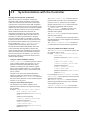
WTViewerFreePlus
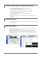
WTViewerFreePlus is a dedicated software application for the WT310/WT310HC/WT330. It is
included in the accompanying CD.
By using WTViewerFreePlus, you can display measured data on a dedicated window, save
measured data to the PC, and change the WT310/WT310HC/WT330 settings from the PC.
For information on how to install and use WTViewerFreePlus, see the WTViewerFreePlus User’s
Manual, IM 760121-02E.
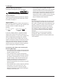
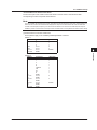
Example of a Window for Configuring the WT
ii
Example of a Window Showing the Measured Data
IM WT310-17EN
Conventions Used in This Manual
Notes
The notes and cautions in this manual are categorized using the following symbols.
WARNING
Calls attention to actions or conditions that could cause serious or fatal
injury to the user, and precautions that can be taken to prevent such
occurrences.
CAUTION
Calls attention to actions or conditions that could cause light injury to the
user or cause damage to the instrument or user’s data, and precautions
that can be taken to prevent such occurrences.
Note Calls attention to information that is important for proper operation of the
instrument.
Units
k
K
Denotes 1000. Example: 100 kHz
Denotes 1024. Example: 720 KB (file size)
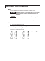
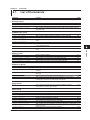
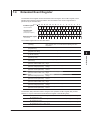
Characters That Appear on the 7-Segment LED
Because this instrument uses a 7-segment LED display, numbers, letters, and mathematical
symbols are displayed using special characters in the manner shown below. Some of the characters
shown below are not used by this instrument.
IM WT310-17EN
0
1
2
3
4
5
6
7
8
9
A
B
C
D
E
F
G
H
I
J
Lowercase c
Lowercase h
K
L
M
N
O
P
Q
R
S
T
U
V
W
X
Y
Z
+
–
×
÷
^ (exponentiation)
iii
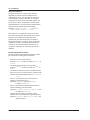
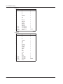
How to Use This Manual
Symbols and Conventions Used in Procedural Explanations
In chapters 1 to 4, the contents of the procedural explanations are indicated using the following
symbols.
Procedure
Operations are explained using flowcharts. See the example below for an
explanation of how various operations are indicated. All procedures are written
under the assumption that you are starting operation at the beginning of the
procedure, so you may not need to carry out all the steps in a procedure when
you are changing the settings.
Example: Operations for setting the GP-IB address
Select the
communication function.
1.
(Display B)
3.
Set the address.
(Display D)
6.
2.
Set, close menu.
4. Press
and
5. Press
to set the number.
to move the digit.
The above flow chart indicates the following operations.
You can configure items that are blinking.
1. Press INTERFACE.
A menu appears in display B.
2. Use ▲ or ▼ to select GPib.
Pressing either key cycles through 4 menu items.
3. Press SET to confirm the selection of GPib.
The GPib function menu that you selected in step 2 appears in display D.
4. Use ▲ or ▼ to select the GP-IB address.
5. If necessary, press the SHIFT key so that it illuminates, and then press ▼ to move the input
digit.
6. Press SET to confirm the setting and return the menu display to the measurement data display.
The selected or set item is confirmed when you press SET.
• When you are making a number positive (no sign) or negative (–) or setting a number, when the
digit in the display that the input will be added to is blank, an underscore flashes at the position
of the digit.
• While you are performing menu operations, to leave the menu display, press HOLD (ESC). All
setting changes that you have confirmed by pressing the SET key will be reflected in the settings.
Explanation This section describes the setup items and the limitations regarding the
procedures.
Symbols Used in the Syntax
The following table contains the symbols that are used in the syntax discussed mainly in chapters 5
and 6. These symbols are referred to as BNF (Backus-Naur Form) symbols. For details on how to
write data using these symbols, see pages 5-6 and 5-7.
Symbol
<>
{}
|
[]
iv
Meaning
A defined value
Select an option in { }
Exclusive OR
Can be omitted
Example
ELEMent<x> <x> = 1 to 3
MODE {RMS|VMEan|DC}
Example of Input
ELEMENT2
MODE RMS
NUMeric[:NORMal]:VALue?
NUMERIC:VALUE?
IM WT310-17EN
Contents
1
About the USB Interface and Ethernet Interface............................................................................... ii
Sample Programs.............................................................................................................................. ii
WTViewerFreePlus............................................................................................................................ ii
Conventions Used in This Manual.................................................................................................... iii
3
Chapter 1 USB Interface
1.1
1.2
1.3
1.4
Component Names and Functions.................................................................................... 1-1
USB Interface Features and Specifications....................................................................... 1-2
Connecting to the USB Interface....................................................................................... 1-3
Configuring the WT310/WT310HC/WT330 USB Settings................................................. 1-4
Chapter 2 GP-IB Interface
2.1
2.2
2.3
2.4
2.5
Component Names and Functions.................................................................................... 2-1
GP-IB Interface Features and Specifications.................................................................... 2-2
Connecting to the GP-IB Interface.................................................................................... 2-4
Configuring the WT310/WT310HC/WT330 GP-IB Settings.............................................. 2-6
Responses to Interface Messages.................................................................................... 2-7
Chapter 3 RS-232 Interface
3.1
3.2
3.3
3.4
Component Names and Functions.................................................................................... 3-1
RS-232 Interface Features and Specifications.................................................................. 3-2
Connecting to the RS-232 Interface.................................................................................. 3-3
Configuring the WT310/WT310HC/WT330 RS-232 Settings............................................ 3-5
Chapter 4 Ethernet Interface
4.1
4.2
4.3
4.4
Component Names and Functions.................................................................................... 4-1
Ethernet Interface Features and Specifications................................................................ 4-2
Connecting to the Ethernet Interface................................................................................. 4-3
Configuring the WT310/WT310HC/WT330 Ethernet Settings.......................................... 4-4
Chapter 5 Programming Overview
5.1
5.2
5.3
5.4
5.5
Messages.......................................................................................................................... 5-1
Commands........................................................................................................................ 5-3
Responses........................................................................................................................ 5-5
Data................................................................................................................................... 5-6
Synchronization with the Controller................................................................................... 5-8
Chapter 6 Commands
6.1
6.2
6.3
6.4
6.5
6.6
6.7
6.8
6.9
6.10
6.11
IM WT310-17EN
2
List of Commands............................................................................................................. 6-1
AOUTput Group................................................................................................................ 6-5
COMMunicate group......................................................................................................... 6-6
DISPlay group................................................................................................................... 6-7
HARMonics Group............................................................................................................ 6-9
HOLD Group................................................................................................................... 6-10
INPut Group.....................................................................................................................6-11
INTEGrate Group............................................................................................................ 6-15
MATH Group................................................................................................................... 6-16
MEASure Group.............................................................................................................. 6-17
NUMeric Group............................................................................................................... 6-18
4
5
6
7
8
App
Index
Contents
6.12
6.13
6.14
6.15
6.16
6.17
RATE Group.................................................................................................................... 6-28
RECall Group.................................................................................................................. 6-29
STATus group.................................................................................................................. 6-30
STORe Group................................................................................................................. 6-31
SYSTem Group............................................................................................................... 6-32
Common Command Group............................................................................................. 6-33
Chapter 7 Status Reports
7.1
7.2
7.3
7.4
7.5
About Status Reports........................................................................................................ 7-1
Status Byte........................................................................................................................ 7-3
Standard Event Register................................................................................................... 7-4
Extended Event Register................................................................................................... 7-5
Output and Error Queues.................................................................................................. 7-6
Chapter 8 WT210/WT230 Compatible Commands
8.1
Appendix
WT210/WT230 Compatible Command Mode................................................................... 8-1
Appendix 1
Appendix 2
Error Messages................................................................................................... App-1
About the IEEE 488.2-1992 Standard................................................................. App-5
Index
vi
IM WT310-17EN
Chapter 1
1.1
USB Interface
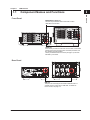
Component Names and Functions
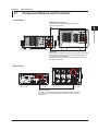
USB Interface
Front Panel
1
2
INTERFACE key (page 1-4)
Press this key to view the serial number that is used in
USB TMC communication.
3
4
5
LOCAL key
Press this key to switch to local mode. In local mode, remote mode
(remote control using communication commands) is cleared, and
key operation becomes possible.
This key is disabled when local lockout (see page 1-2) has been
activated by a controller.
6
7
8
Rear Panel
App
Index
USB port
This port is for connecting the WT310/WT310HC/WT330 to a
controller (such as a PC) using a USB cable. For details on
how to connect, see page 1-3.
IM WT310-17EN
1-1
1.2
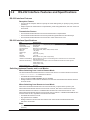
USB Interface Features and Specifications
USB Interface Features
Reception Feature
• You can use the reception feature to specify the same settings that you specify by using the front
panel keys.
• Output requests for measured and computed data, panel setup parameters, and error codes can
be received.
Transmission Feature
• The WT310/WT310HC/WT330 can transmit measured and computed data.
• The WT310/WT310HC/WT330 can transmit panel setup parameters and the status byte.
• The WT310/WT310HC/WT330 can transmit error codes when errors occur.
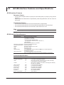
USB Interface Specifications
Item
Number of ports
Connector
Electrical and mechanical
Supported transfer modes
Supported protocols
PC system requirements
Specifications
1
Type B connector (receptacle)
Complies with USB Rev. 2.0
HS (High Speed; 480 Mbps) and FS (Full Speed; 12 Mbps)
USBTMC-USB488 (USB Test and Measurement Class Ver. 1.0)
PC running Windows 7 (32 bit/64 bit), Vista (32 bit), XP (SP2 and later; 32bit)
English and Japanese and with a USB port
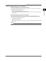
Switching between Remote and Local Modes
When Switching from Local to Remote Mode
The WT310/WT310HC/WT330 switches to remote mode when it is in local mode and it receives a :
COMMunicate:REMote ON command from the PC.
• The REMOTE indicator illuminates.
• All keys except the SHIFT (LOCAL) key are disabled.
• Settings entered in local mode are retained even when the WT310/WT310HC/WT330 switches
to remote mode.
When Switching from Remote to Local Mode
When the WT310/WT310HC/WT330 is in remote mode and you press SHIFT (LOCAL), the WT310/
WT310HC/WT330 switches to local mode. However, this does not work if the WT310/WT310HC/
WT330 has received a :COMMunicate:LOCKout ON command from the PC. The WT310/
WT310HC/WT330 switches to local mode when it receives a :COMMunicate:REMote OFF
command from the PC, regardless of the local lockout state.
• The REMOTE indicator turns off.
• Key operations are enabled.
• Settings entered in remote mode are retained even when the WT310/WT310HC/WT330 switches
to local mode.
Note
You cannot use the USB interface simultaneously with other interfaces (GP-IB, RS-232, and Ethernet
interfaces).
1-2
IM WT310-17EN
1.3
Connecting to the USB Interface
1
USB Interface
2
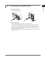
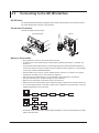
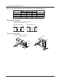
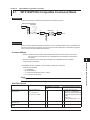
Connection Procedure
Connect the cable as shown below.
WT310/WT310HC
WT330
3
4
5
Notes on Connection
• Be sure to insert the USB cable connectors firmly into the USB ports.
• If you are connecting multiple devices by using a USB hub, connect the WT310/WT310HC/
WT330 to the USB hub port that is closest to the port that the controller is connected to.
• Do not connect or remove USB cables from the time when the WT310/WT310HC/WT330 is
turned on until operation becomes available (approximately 20 to 30 seconds). Doing so may
damage the WT310/WT310HC/WT330.
• On the WT310 and WT310HC, it is physically impossible to connect a GP-IB cable and a USB
cable at the same time.
6
7
8
App
Index
IM WT310-17EN
1-3
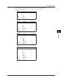
1.4
Configuring the WT310/WT310HC/WT330 USB
Settings
This section explains the following setting for controlling the WT310/WT310HC/WT330 remotely
through a USB interface:
Procedure
Follow the procedure indicated by the thick lines in the following menu.
•
Viewing the serial number that is used in USB TMC communications
1.
Select the
communication function.
(Display B)
2.
or
3.
Instrument number
is shown in displays
C and D.
Close menu.
Note
• Only use one communication interface: USB, GP-IB, RS-232, or Ethernet. If you send commands
simultaneously from more than one communication interface, the WT310/WT310HC/WT330 will not
execute the commands properly.
• Install the YOKOGAWA USB TMC (Test and Measurement Class) driver on your PC. For information
about how to obtain the YOKOGAWA USB TMC driver, contact your nearest YOKOGAWA dealer. You can
also access the YOKOGAWA USB driver download web page and download the driver.
http://tmi.yokogawa.com/
• Do not use USB TMC drivers (or software) supplied by other companies.
1-4
IM WT310-17EN
Chapter 2
2.1
GP-IB Interface
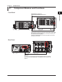
Component Names and Functions
Front Panel
1
2
GP-IB Interface
INTERFACE key (page 2-6)
Press this key to set the GP-IB address.
3
4
5
LOCAL key
Press this key to switch to local mode. In local mode, remote mode
(remote control using communication commands) is cleared, and
key operation becomes possible.
This key is disabled when local lockout (see page 2-3) has been
activated by a controller.
Rear Panel
6
7
8
App
Index
GP-IB port
This port is for connecting the WT310/WT310HC/WT330 to a controller
(such as a PC) using a GP-IB cable. For details on how to connect, see
page 2-4.
IM WT310-17EN
2-1
2.2
GP-IB Interface Features and Specifications
GP-IB Interface Features
Reception Feature
• You can use the reception feature to specify the same settings that you specify by using the front
panel keys.
• Output requests for measured and computed data, panel setup parameters, and error codes can
be received.
Transmission Feature
• The WT310/WT310HC/WT330 can transmit measured and computed data.
• The WT310/WT310HC/WT330 can transmit panel setup parameters and the status byte.
• The WT310/WT310HC/WT330 can transmit error codes when errors occur.
Note
Talk-only, listen-only, and controller capabilities are not available.
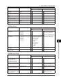
GP-IB Interface Specifications
Item
Supported devices
Specifications
National Instruments Corporation
• PCI-GPIB or PCI-GPIB+
• PCIe-GPIB or PCIe-GPIB+
• PCMCIA-GPIB or PCMCIA-GPIB+
(not supported on Windows Vista or Windows 7.)
• GPIB-USB-HS
Driver NI-488.2M Version 2.8.1 and later
Electrical and mechanical Conforms to IEEE St’d 488-1978
Functional specifications See the table below.
Protocol
Conforms to IEEE St’d 488.2-1992
Code
ISO (ASCII) codes
Mode
Addressable mode
Address setting
Press INTERFACE, and then select the GPIB menu. Set the address to a
value between 0 and 30.
Clear remote mode
Press SHIFT (LOCAL) to clear remote mode.
This is not possible when local lockout has been activated by the controller.
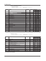
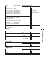
Functional Specifications
2-2
Function
Source handshaking
Acceptor handshaking
Talker
Subset Name
SH1
AH1
T6
Listener
L4
Service request
Remote local
Parallel polling
Device clear
Device trigger
Controller
Electric characteristics
SR1
RL1
PP0
DC1
DT1
C0
E1
Description
Full source handshaking capability
Full acceptor handshaking capability
Basic talker capability, serial polling, and untalk on MLA (My
Listen Address). No talk-only capability.
Basic listener capability and unlisten on MTA (My Talk Address).
No listen-only capability
Full service request capability
Full remote/local capability
No parallel polling capability
Full device clear capability
Device trigger capability
No controller capability
Open collector
IM WT310-17EN
2.2 GP-IB Interface Features and Specifications
1
Switching between Remote and Local Modes
When Switching from Local to Remote Mode
When Switching from Remote to Local Mode
When the WT310/WT310HC/WT330 is in remote mode and you press SHIFT (LOCAL), the
WT310/WT310HC/WT330 switches to local mode. This key is disabled when local lockout (see
page 2-7) has been activated by a controller.
• The REMOTE indicator turns off.
• Key operations are enabled.
• Settings entered in remote mode are retained even when the WT310/WT310HC/WT330 switches
to local mode.
Note
2
GP-IB Interface
The WT310/WT310HC/WT330 switches to remote mode when it is in local mode and it receives a
REN (Remote Enable) message from the PC.
• The REMOTE indicator illuminates.
• All keys except the SHIFT (LOCAL) key are disabled.
• Settings entered in local mode are retained even when the WT310/WT310HC/WT330 switches
to remote mode.
3
4
5
6
You cannot use the GP-IB interface simultaneously with other interfaces (USB and Ethernet interfaces).
7
8
App
Index
IM WT310-17EN
2-3
2.3
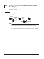
Connecting to the GP-IB Interface
GP-IB Cable
The WT310/WT310HC/WT330 is equipped with an IEEE St’d 488-1978 24-pin GP-IB connector.
Use a GP-IB cable that conforms to this standard.
Connection Procedure
Connect the cable as shown below.
WT310/WT310HC
WT330
Notes on Connection
• Firmly tighten the screws on the GP-IB cable connector.
• On the PC end, use a GP-IB board (or card) made by National Instruments. For details, see
section 2.2.
• The WT310/WT310HC/WT330 may not operate properly if the WT310/WT310HC/WT330 is
connected to the PC through converters (such as a GP-IB to USB converter). For more details,
contact your nearest YOKOGAWA dealer.
• Several cables can be used to connect multiple devices. However, no more than 15 devices,
including the controller, can be connected on a single bus.
• When connecting multiple devices, you must assign a unique address to each device.
• Use cables that are 2 m or shorter in length to connect devices.
• Make sure the total length of all cables does not exceed 20 m.
• When devices are communicating, have at least two-thirds of the devices on the bus turned on.
• To connect multiple devices, use a star or daisy-chain configuration as shown below. Loop and
parallel configurations are not allowed.
• On the WT310 and WT310HC, it is physically impossible to connect a GP-IB cable and a USB
cable at the same time.
2-4
IM WT310-17EN
2.3 Connecting to the GP-IB Interface
1
CAUTION
Be sure to turn off the PC and the WT310/WT310HC/WT330 before you connect or remove
communication cables. Otherwise, erroneous operation may result, or the internal circuitry
may break.
2
GP-IB Interface
3
4
5
6
7
8
App
Index
IM WT310-17EN
2-5
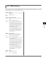
2.4
Configuring the WT310/WT310HC/WT330 GPIB Settings
This section explains the following setting for controlling the WT310/WT310HC/WT330 remotely
through a GP-IB interface:
Procedure
Follow the procedure indicated by the thick lines in the following menu.
Setting the GP-IB Address
Select the
communication function.
1.
(Display B)
3.
Set the address.
(Display D)
6.
2.
Set, close menu.
4. Press
5. Press
and
to set the number.
to move the digit.
Note
• Only use one communication interface: USB, GP-IB, or Ethernet. If you send commands simultaneously
from more than one communication interface, the WT310/WT310HC/WT330 will not execute the
commands properly.
• When the controller is communicating with the WT310/WT310HC/WT330 or with other devices through
GP-IB, do not change the address.
• Each device that is connected by GP-IB has its own unique address in the GP-IB system. This address
is used to distinguish between different devices. Therefore, you must assign a unique address to the
WT310/WT310HC/WT330 when connecting it to a PC or other device.
2-6
IM WT310-17EN
2.5
Responses to Interface Messages
1
2
Responses to Interface Messages
GP-IB Interface
Responses to Uni-Line Messages
• IFC (Interface Clear)
3
Clears the talker and listener functions. Stops data transmission if it is in progress.
• REN (Remote Enable)
Switches between the remote and local modes.
4
IDY (Identify) is not supported.
Responses to Multi-Line Messages (Address commands)
5
• GTL (Go To Local)
Switches the instrument to local mode.
• SDC (Selected Device Clear)
• Clears the program message (command) being received and the output queue (see page 7-6
for details).
• Discards *OPC and *OPC? commands that are being executed.
• Immediately aborts *WAI and COMMunicate:WAIT commands.
6
7
• GET (Group Execute Trigger)
The same operation as the *TRG command.
8
PPC (Parallel Poll Configure) and TCT (Take Control) are not supported.
Responses to Multi-Line Messages (Universal commands)
• LLO (Local Lockout)
App
Prohibits switching to local mode by disabling the LOCAL key on the front panel.
• DCL (Device Clear)
Index
The same operation as the SDC message.
• SPE (Serial Poll Enable)
Sets the talker function on all devices on the bus to serial polling mode. The controller will poll
each device one by one.
• SPD (Serial Poll Disable)
Clears the serial polling mode of the talker function on all devices on the bus.
PPU (Parallel Poll Unconfigure) is not supported.
What Are Interface Messages?
Interface messages are also referred to as interface commands or bus commands. They are
commands that are issued by the controller. They are classified as follows:
Uni-line Messages
A single control line is used to transmit uni-line messages. The following three types are available.
• IFC (Interface Clear)
• REN (Remote Enable)
• IDY (Identify)
IM WT310-17EN
2-7
2.5 Responses to Interface Messages
Multi-line Messages
Eight data lines are used to transmit multi-line messages. The messages are classified as follows:
• Address Commands
Some address commands are valid when a device is designated as a listener, and some are
valid when it is designated as a talker. The following five commands are available.
Commands available to a device designated as a listener
• GTL (Go To Local)
• SDC (Selected Device Clear)
• PPC (Parallel Poll Configure)
• GET (Group Execute Trigger)
Commands available to a device designated as a talker
• TCT (Take Control)
• Universal Commands
Universal commands are available to all devices regardless of their listener or talker designation.
The following five commands are available.
• LLO (Local Lockout)
• DCL (Device Clear)
• PPU (Parallel Poll Unconfigure)
• SPE (Serial Poll Enable)
• SPD (Serial Poll Disable)
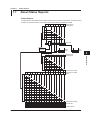
There are other interface messages: listener-address, talk-address, and secondary commands.
Uni-line
messages
IFC
REN
IDY
Listener
Address
Interface messages
Multi-line Messages
Address
commands
Universal
commands
GTL
SDC
PPC
GET
TCT
LLO
DCL
PPU
SPE
SPD
Talker
Address
2
Command
The WT310/WT310HC/WT330 supports interface messages marked with a «.
Note
Difference between SDC and DCL
In multi-line messages, SDC messages are those that require talker or listener designation and DCL
messages are those that do not require a designation. Therefore, SDC messages are directed at a particular
instrument while DCL messages are directed at all instruments on the bus.
2-8
IM WT310-17EN
Chapter 3
3.1
RS-232 Interface
Component Names and Functions
Front Panel
1
2
INTERFACE key (page 3-5)
Press this key to set the handshaking, data format,
baud rate, or terminator.
3
RS-232 Interface
4
5
LOCAL key
Press this key to switch to local mode. In local mode, remote mode
(remote control using communication commands) is cleared, and
key operation becomes possible.
This key is disabled when local lockout (see page 3-2) has been
activated by a controller.
6
7
8
Rear Panel
App
Index
RS-232 connector
This port is for connecting the WT310/WT310HC/WT330 to a controller
(such as a PC) using an RS-232 cable. For details on how to connect,
see page 3-4.
IM WT310-17EN
3-1
3.2
RS-232 Interface Features and Specifications
RS-232 Interface Features
Reception Feature
• You can use the reception feature to specify the same settings that you specify by using the front
panel keys.
• Output requests for measured and computed data, panel setup parameters, and error codes can
be received.
Transmission Feature
• The WT310/WT310HC/WT330 can transmit measured and computed data.
• The WT310/WT310HC/WT330 can transmit panel setup parameters and the status byte.
• The WT310/WT310HC/WT330 can transmit error codes when errors occur.
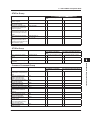
RS-232 Interface Specifications
Item
Electrical specifications
Connection
Transmission mode
Synchronization
Baud rate
Start bit
Data length
Parity
Stop bits
Connector
Hardware handshaking
Software handshaking
Receive buffer size
Specifications
Complies with EIA-574 (EIA-232 (RS-232) standard for 9-pin)
Point to point
Full duplex
Start-stop synchronization
1200, 2400, 4800, 9600, 19200, 38400, 57600
1 bit (fixed)
7 or 8 bits
Even, odd, no parity
1 or 2 bits
DELC-J9PAF-13L6 (JAE or equivalent)
Select whether to use the CA and CB signals as controller lines or assume that
they are always true.
Transmission and reception can be controlled with X-ON and X-OFF signals.
X-ON (ASCII 11H)
X-OFF (ASCII 13H)
256 bytes.
Switching between Remote and Local Modes
When Switching from Local to Remote Mode
The WT310/WT310HC/WT330 switches to remote mode when it is in local mode and it receives a
:COMMunicate:REMote ON command from the PC.
• The REMOTE indicator illuminates.
• All keys except the SHIFT (LOCAL) key are disabled.
• Settings entered in local mode are retained even when the WT310/WT310HC/WT330 switches
to remote mode.
When Switching from Remote to Local Mode
When the WT310/WT310HC/WT330 is in remote mode and you press SHIFT (LOCAL), the
WT310/WT310HC/WT330 switches to local mode. However, this does not work if the WT310/
WT310HC/WT330 has received a :COMMunicate:LOCKout ON command from the PC. The
WT310/WT310HC/WT330 switches to local mode when it receives a :COMMunicate:REMote OFF
command from the PC, regardless of the local lockout state.
• The REMOTE indicator turns off.
• Key operations are enabled.
• Settings entered in remote mode are retained even when the WT310/WT310HC/WT330
switches to local mode.
Note
You cannot use the RS-232 interface simultaneously with other communication interfaces (USB and Ethernet
interfaces).
3-2
IM WT310-17EN
3.3
Connecting to the RS-232 Interface
1
To connect the WT310/WT310HC/WT330 to a PC, use an interface cable that is compatible with
the WT310/WT310HC/WT330 specifications. Be sure to align the handshaking, data transfer rate,
data format, and so on with the PC. For the settings, see section 3.4.
3
Connector and Signal Names
2 3 4
WT330
5
6
7
8
9
8 9
6 7
RS-232 Interface
WT310/WT310HC
1
2
4
1
2
3
4
5
5
DELC-J9PAF-13L6 or equivalent
Pin No.
2
3
5
7
8
Signal Name
RD (Received Data)
SD (Send Data)
SG (Signal Ground)
RS (Request to Send)
CS (Clear to Send)
Input or Output
Input
Output
---Output
Input
Function
Data received from the PC
Data sent to the PC
Signal ground
Handshaking signal for receiving data from the PC
Handshaking signal for sending data to the PC
* Pins 1, 4, 6, and 9 are not used.
9-pin to 25-pin Adapter and Signal Names
App
3 2 7
(2) (3) (4)
8
(5)
5
(7)
Numbers in parentheses are pin numbers for the 25-pin connector.
Index
Signal Direction
The following figure shows the directions of the signals of the WT310/WT310HC/WT330 RS-232
interface.
IM WT310-17EN
7
8
6
PC
RS [Request to send]
7
CS [Clear to send]
8
SD [Send data]
3
RD [Receive data]
2
WT310/
WT310HC/
WT330
3-3
3.3 Connecting to the RS-232 Interface
RS-232 Standard Signals and Their JIS and CCITT Abbreviations
Pin No.
(9-pin connector)
5
3
2
7
8
RS-232
AB (GND)
BA (TXD)
BB (RXD)
CB (CTS)
CA (RTS)
Abbreviation
CCITT
102
103
104
105
106
Name
JIS
SG
SD
RD
RS
CS
Signal ground
Transmitted data
Request to send
Received data
Clear to send
Signal Wiring Example
The pin numbers are for the 9-pin connector.
In general, use a crossover cable.
OFF-OFF / XON-XON
WT
PC
SD
RD
RS
CS
SG
3
2
7
8
5
3
2
7
8
5
SD
RD
RS
CS
SG
CTS-RTS (CS-RS)
WT
PC
SD
RD
RS
CS
SG
3
2
7
8
5
3
2
7
8
5
SD
RD
RS
CS
SG
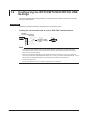
Connection Procedure
Connect the cable as shown below.
WT310/WT310HC
WT330
3-4
IM WT310-17EN
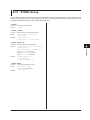
3.4
Configuring the WT310/WT310HC/WT330
RS-232 Settings
1
2
This section explains the following setting for controlling the WT310/WT310HC/WT330 remotely
through a RS-232 interface:
Procedure
3
Follow the procedure indicated by the thick lines in the following menu.
Set the handshaking.
(Display A)
3.
2.
Set the data format.
(Display B)
5.
RS-232 Interface
Select the
communication function.
(Display B)
1.
7.
4
6.
4.
5
Set the baud rate.
(Display C)
8.
9.
Set the terminator.
(Display D)
10.
11.
6
Set, close menu.
7
8
Note
Only use one communication interface: USB, RS-232, or Ethernet. If you send commands simultaneously
from more than one communication interface, the WT310/WT310HC/WT330 will not execute the commands
properly.
App
Index
IM WT310-17EN
3-5
3.4 Configuring the WT310/WT310HC/WT330 RS-232 Settings
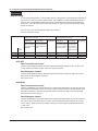
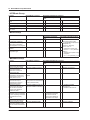
Explanation
Handshaking
To use the RS-232 interface to communicate with a PC, the devices on both sides must negotiate a
set of rules to ensure the proper transfer of data. This negotiation is called handshaking. Because
there are many handshaking methods that can be used between the WT310/WT310HC/WT330
and the PC, you must make sure that the same method is chosen by both the WT310/WT310HC/
WT330 and the PC.
You can choose any of handshaking methods shown below.
NO-NO, XON-XON, CS-RS
Handshaking
WT
Menu
Data Transmission Control
(Sending data to the PC)
Software
Hardware
No
Handshaking
Handshaking
handshaking
Stop sending when Stop sending when
X-OFF is received; CB (CTS) is false;
resume when X-ON resume when it is
is received.
true.
OFF-OFF HAnd 0
XON-XON HAnd 1 Yes
CS-RS
HAnd 2
Data Reception Control
(Receiving data from the PC)
Software
Hardware
No
Handshaking
Handshaking
handshaking
Send X-OFF when Set CA (RTS) to
the receive buffer is false when the
3/4 full; send X-ON receive buffer is
when it is 1/4 full.
3/4 full; set CA
(RTS) to it is 1/4
full.
Yes
Yes
Yes
Yes
Yes
OFF-OFF
Data Transmission Control
There is no handshaking between the WT310/WT310HC/WT330 and the PC. The “X-OFF” and
“X-ON” signals are treated as data, and the CS signal is ignored.
Data Reception Control
There is no handshaking between the WT310/WT310HC/WT330 and the PC. When the receive
buffer is full, excessive data is discarded.
RS is fixed to true.
XON-XON
Data Transmission Control
Software handshaking is performed between the WT310/WT310HC/WT330 and the PC. When the
WT310/WT310HC/WT330 receives an “X-OFF” code from the PC while it is sending data, it stops
the data transmission. It resumes the operation when it receives a “X-ON” code. The CS signal
received from the PC is ignored.
Data Reception Control
Software handshaking is performed between the WT310/WT310HC/WT330 and the PC. When the
free area of the receive buffer falls to 64 bytes, the WT310/WT310HC/WT330 sends an “X-OFF”
code to the PC. When the free area reaches 192 bytes, the WT310/WT310HC/WT330 sends an
“X-ON” code.
RS is fixed to true.
3-6
IM WT310-17EN
3.4 Configuring the WT310/WT310HC/WT330 RS-232 Settings
1
CS-RS
Data Transmission Control
Hardware handshaking is performed between the WT310/WT310HC/WT330 and the PC. If CS
is set to false while the WT310/WT310HC/WT330 is sending data, it stops the data transmission.
Then, if CS is set to true, it resumes the operation. The “X-OFF” and “X-ON” signals are treated as
data.
Data Reception Control
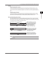
Notes on Data Reception Control
When handshaking is used to control the reception of data, data may still be received from the PC
even when the free space in the receive buffer drops below 64 bytes. In such cases, if the receive
buffer becomes full, excessive data will be discarded, regardless of the handshaking method. When
more space becomes available, data storage resumes.
Data reception control using handshaking
256 bytes
Used
Used
Free, 192 bytes
Used
Free, 64 bytes
4
5
6
When handshaking is in use and
the free space in the buffer drops
to 64 bytes (because the data in
the buffer cannot be passed to
the internal program fast
enough), data reception stops.
7
Data continues to be passed to the
internal program. If the free space
in the buffer reaches 192 bytes,
data reception resumes.
8
App
Regardless of the handshaking
method, if the buffer becomes full,
excessive data will be discarded.
Index
Note
You must design PC programs so that the receive buffers of both the WT310/WT310HC/WT330 and PC do
not become full.
IM WT310-17EN
3
RS-232 Interface
Hardware handshaking is performed between the WT310/WT310HC/WT330 and the PC. When
the free area of the receive buffer falls to 64 bytes, the WT310/WT310HC/WT330 sets RS to false.
When the free area reaches 192 bytes, the WT310/WT310HC/WT330 sets RS to true.
2
3-7
3.4 Configuring the WT310/WT310HC/WT330 RS-232 Settings
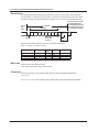
Data Format
The WT310/WT310HC/WT330 RS-232 interface performs communication using start-stop
synchronization. In start-stop synchronization, characters are transmitted one at a time. Each
character consists of a start bit, data bits, a parity bit, and a stop bit (see the following figure).
The circuit returns to the
idle state (dotted line)
or is activated (solid line)
if the start bit of the next
piece of data is available.
1 character
Circuit
idle
state
Data bits
(7 or 8 bits)
Stop
bits
1
Parity bit
Even, odd,
or none
Start bit
1 or 2
2
Select the data length and parity stop bit from the following options.
8-NO-1, 7-EVEN-1, 7-ODD-1, 7-NO-2
Baud rate
Terminator
WT Menu
Start bit
For 0
For 1
For 2
For 3
1
1
1
1
Data
length
8
7
7
7
Parity
Stop bits
None
Odd
Even
None
1
1
1
2
Select from the following baud rates.
1200, 2400, 4800, 9600, 19200, 38400, 57600
Select the terminator to use when sending data from the WT310/WT310HC/WT330.
Cr, Lf, Cr+Lf
Use “LF” or “Cr+Lf” for the terminator when sending data to the WT310/WT310HC/WT330.
3-8
IM WT310-17EN
Chapter 4
4.1
Ethernet Interface
Component Names and Functions
Front Panel
1
2
UTILITY key (page 4-4)
Press this key to configure TCP/IP settings.
3
4
Ethernet Interface
5
LOCAL key
Press this key to switch to local mode. In local mode, remote mode
(remote control using communication commands) is cleared, and
key operation becomes possible.
This key is disabled when local lockout (see page 4-2) has been
activated by a controller.
Rear Panel
6
7
8
App
Index
Ethernet port
This port is for connecting the WT310/WT310HC/WT330 to a controller
(such as a PC) using an Ethernet cable. For details on how to connect,
see page 4-3.
IM WT310-17EN
4-1
4.2
Ethernet Interface Features and Specifications
Ethernet Interface Features
Reception Feature
• You can use the reception feature to specify the same settings that you specify by using the front
panel keys.
• Output requests for measured and computed data, panel setup parameters, and error codes can
be received.
Transmission Feature
• The WT310/WT310HC/WT330 can transmit measured and computed data.
• The WT310/WT310HC/WT330 can transmit panel setup parameters and the status byte.
• The WT310/WT310HC/WT330 can transmit error codes when errors occur.
Ethernet Interface Specifications
Item
Electrical and mechanical
Simultaneous connections
Communication protocol
Connector type
Specifications
IEEE802.3
2
TCP/IP (VXI-11)
RJ-45
Switching between Remote and Local Modes
When Switching from Local to Remote Mode
The WT310/WT310HC/WT330 switches to remote mode when it is in local mode and it receives a
:COMMunicate:REMote ON command from the PC.
• The REMOTE indicator illuminates.
• All keys except the SHIFT (LOCAL) key are disabled.
• Settings entered in local mode are retained even when the WT310/WT310HC/WT330 switches
to remote mode.
When Switching from Remote to Local Mode
When the WT310/WT310HC/WT330 is in remote mode and you press SHIFT (LOCAL), the
WT310/WT310HC/WT330 switches to local mode. However, this does not work if the WT310/
WT310HC/WT330 has received a :COMMunicate:LOCKout ON command from the PC. The
WT310/WT310HC/WT330 switches to local mode when it receives a :COMMunicate:REMote
OFF command from the PC, regardless of the local lockout state.
• The REMOTE indicator turns off.
• Key operations are enabled.
• Settings entered in remote mode are retained even when the WT310/WT310HC/WT330
switches to local mode.
Note
You cannot use the Ethernet interface simultaneously with other interfaces (GP-IB, RS-232, and USB).
4-2
IM WT310-17EN
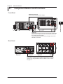
4.3
Connecting to the Ethernet Interface
1
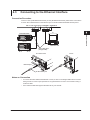
Connection Procedure
Connect a UTP (Unshielded Twisted-Pair) or STP (Shielded Twisted-Pair) cable that is connected to
a hub or other network device to the Ethernet port on the WT310/WT310HC/WT330 rear panel.
3
Hub or router that supports 1000BASE-T/100BASE-TX
4
PC
WT310/WT310HC
2
Ethernet Interface
5
WT330
6
Network card
UTP or STP cable
(straight cable)
WT310/WT310HC
7
WT330
8
Ethernet port
App
RJ-45 modular jack
Index
Notes on Connection
• To connect the WT310/WT310HC/WT330 to a PC, be sure to use straight cables and to connect
through a hub or router. Proper operation is not guaranteed for a one-to-one connection using a
crossover cable.
• Use a network cable that supports the data rate of your network.
IM WT310-17EN
4-3
4.4
Configuring the WT310/WT310HC/WT330
Ethernet Settings
This section explains the following setting for remotely controlling the WT310/WT310HC/WT330 via
the Ethernet interface:
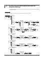
Procedure
Follow the procedure indicated by the thick lines in the following menu.
1.
Select Ethernet.
(Display B)
2.
Select DHCP.
(Display B)
3.
5.
4.
(Display C)
6.
8.
7.
Confirm the setting.
7.
Close menu.
(User settings)
Select IP address.
(Display B)
8.
9.
Set the IP address.
(Display C)
10. Press
and
11. Press
12.
Set the IP address.
(Display D)
to set the number. 13.
to move the digit.
14.
15.
Same as step 10
and 11
Select subnet mask.
(Display B)
16.
17.
Set the subnet mask.
(Display C)
20.
18.
19.
Same as step 10 and 11
Set the subnet mask.
(Display D)
23.
21.
22.
Same as step 10 and 11
Select default gateway.
(Display B)
24.
25.
Set the default gateway.
(Display C)
28.
26.
27.
Select to apply the settings.
(Display B)
Same as step 10 and 11
Set the default gateway.
(Display D)
31.
29.
30.
Same as step 10 and 11
32.
33.
Apply the settings.
(Display C)
34.
35.
Close menu.
4-4
IM WT310-17EN
4.4 Configuring the WT310/WT310HC/WT330 Ethernet Settings
Note
Only use one communication interface: USB, GP-IB, RS-232, or Ethernet. If you send commands
simultaneously from more than one communication interface, the WT310/WT310HC/WT330 will not execute
the commands properly.
1
2
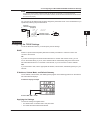
You can view the IP address that has been assigned by the DHCP server or the IP address that you
specified by following the procedure below.
3
Select the
communication function.
1.
(Display B)
2.
or
4
3.
Close menu.
Ethernet Interface
Displays C and D
show the IP address.
5
Explanation
Configuring the TCP/IP Settings
6
To use the Ethernet interface, you must specify TCP/IP settings.
DHCP
7
DHCP is a protocol that temporarily allocates necessary information to a device so that it can
connect to the Internet.
ON
If you are connecting the WT310/WT310HC/WT330 to a network with a DHCP server, you can
turn on the DHCP setting. If you do, the IP address will be automatically assigned to the WT310/
WT310HC/WT330 when it is connected to the network, so you do not have to set the address.
8
OFF
If you set DHCP to OFF, set the appropriate IP address, subnet mask, and default gateway for your
network.
IP Address, Subnet Mask, and Default Gateway
The IP address, subnet mask, and default gateway appear in the following positions on the WT310/
WT310HC/WT330 displays.
IP address display example
IP address: 192 . 168 .
0. 100
Applying the Settings
The TCP/IP settings are applied when:
• You select EXEC on the Bind menu and press SET.
• You restart the WT310/WT310HC/WT330.
IM WT310-17EN
4-5
App
Index
Chapter 5
5.1
Programming Overview
Messages
1
Messages
Program Messages
The program message format is shown below.
;
<Program message unit>
<PMT>
The program message unit syntax is shown below.
,
<Program header>
Space
Unit
Unit
<PMT>
This is a program message terminator. The following
three types are available.
NL (new line):
Same as LF (line feed). ASCII
code “0AH.”
^END: The END message as defined by
IEEE 488.1
(The data byte that is sent with
the END message is the last data
byte of the program message.)
NL^END: NL with an END message
attached.
(NL is not included in the program
message.)
IM WT310-17EN
3
<Program data>
<Program Header>
The program header indicates the command type. For
details, see page 5-3.
(Program Data>
Attach program data if there are conditions that are
required to execute a command. Separate the program
data from the header with a space (ASCII code 20H). If
there are multiple sets of program data, separate each
set with a comma.
For details, see page 5-6.
Example :INPut:CFACtor 3<PMT>
Header
<Program Message Unit>
A program message consists of one or more program
message units. Each unit corresponds to one
command. The WT310/WT310HC/WT330 executes
the commands in the order that they are received.
Separate each program message unit with a
semicolon.
For details on the program message syntax, see the
next section.
Example :INPut:MODE RMS;CFACtor 3<PMT>
2
Program Message Unit Syntax
Data
Response Messages
4
5
Programming Overview
Messages are used to exchange information between
the controller and the WT310/WT310HC/WT330.
Messages that are sent from the controller to the
WT310/WT310HC/WT330 are called program
messages, and messages that are sent from the
WT310/WT310HC/WT330 back to the controller are
called response messages.
If a program message contains a command that
requests a response (a query), the WT310/WT310HC/
WT330 returns a response message upon receiving
the program message. The WT310/WT310HC/WT330
returns a single response message in response to a
single program message.
6
7
8
The response message syntax is as follows:
;
<Response message unit>
<RMT>
<Response Message Unit>
A response message consists of one or more response
message units. Each unit corresponds to one
response.
Separate each response message unit with a
semicolon.
For details on the response message syntax, see the
next page.
Example
:INPUT:FILTER:LINE 0;FREQUENCY 0<RMT>
Unit
Unit
<RMT>
RMT is a response message terminator. It is NL^END.
5-1
App
Index
5.1 Messages
Response Message Unit Syntax
The response message unit syntax is as follows:
,
<Response header>
Space
<Response data>
<Response Header>
A response header sometimes precedes the response
data. Separate the data from the header with a space.
For details, see page 5-5.
<Response Data>
Response data contains the content of the response. If
there are multiple sets of response data, separate each
set with a comma. For details, see page 5-5.
Example
100.00E-03<RMT> :INPUT:MODE RMS<RMT>
Data
Header
Data
If there are multiple queries in a program message,
responses are returned in the same order that the
queries were received in. In most cases, a single query
returns a single response message unit, but there
are a few queries that return multiple units. The first
response message unit always corresponds to the first
query, but the nth response unit may not necessarily
correspond to the nth query. Therefore, if you want to
make sure that every response is retrieved, divide the
program messages into individual messages.
• If the controller sends a program message
containing multiple message units, but the message
contains incomplete units, the WT310/WT310HC/
WT330 will try to execute the ones that are believed
to be complete. However, these attempts may not
always be successful. In addition, if such a message
contains queries, the WT310/WT310HC/WT330
may not necessary return responses.
Deadlock
The WT310/WT310HC/WT330 can store at least 1024
bytes of messages in its transmit and receive buffers
(the number of available bytes varies depending on the
operating conditions). If both the transmit and receive
buffers become full at the same time, the WT310/
WT310HC/WT330 will no longer be able to operate.
This condition is called a deadlock. If this happens,
you can resume operation by discarding response
messages.
Deadlock will not occur if the program message
(including the <PMT>) is kept below 1024 bytes.
Program messages that do not contain queries never
cause deadlocks.
Precautions to Be Taken when Sending and
Receiving Messages
• If the controller sends a program message that does
not contain a query, the controller can send the next
program message at any time.
• If the controller sends a program message that
contains a query, the controller must finish receiving
the response message before it can send the next
program message. If the controller sends the next
program message before receiving the response
message in its entirety, an error will occur. A
response message that is not received in its entirety
will be discarded.
• If the controller tries to receive a response message
when there is none, an error will occur. If the
controller tries to receive a response message
before the transmission of the program message is
complete, an error will occur.
5-2
IM WT310-17EN
5.2
Commands
Commands
There are three types of commands (program headers)
that a controller may send to the WT310/WT310HC/
WT330. The commands differ in their program header
formats.
Common Command Header
Commands that are defined in IEEE 488.2-1992 are
called common commands. The common command
header syntax is shown below. Be sure to include an
asterisk (*) at the beginning of a common command.
?
<Mnemonic>
*
Compound Header
Commands, other than common commands, that
are specific to the WT310/WT310HC/WT330 are
classified and arranged in a hierarchy according
to their functions. The compound header syntax is
shown below. Be sure to use a colon to specify a lower
hierarchical level.
:
:
?
<Mnemonic>
Compound header example: :INPut:MODE
Simple Header
These commands are functionally independent and are
not contained within a hierarchy. The format of a simple
header is shown below.
:
<Mnemonic>
?
Simple header example: :HOLD
Note
A <mnemonic> is an alphanumeric character string.
When Concatenating Commands
• Command Groups
A command group is a group of commands that
have common compound headers arranged in a
hierarchy. A command group may contain subgroups.
IM WT310-17EN
2
Example A portion of the commands from the
integration command group
:INTEGrate?
:INTEGrate:MODE
:INTEGrate:TIMer
:INTEGrate:STARt
:INTEGrate:STOP
:INTEGrate:RESet
3
• When Concatenating Commands of the Same
Group
The WT310/WT310HC/WT330 stores the
hierarchical level of the command that is currently
being executed and processes the next command
on the assumption that it belongs to the same
level. Therefore, the common header section can
be omitted for commands that belong to the same
group.
Example :INTEGrate:MODE NORMal;
TIMer 1,0,0<PMT>
• When Concatenating Commands of Different
Groups
If the subsequent command does not belong to the
same group, place a colon in front of the header (this
colon cannot be omitted).
Example :INTEGrate:MODE NORMal;:INPut:
MODE RMS<PMT>
• When Concatenating Simple Headers
If a simple header follows another command, place
a colon in front of the simple header (this colon
cannot be omitted).
Example :INTEGrate:MODE NORMal;:HOLD
ON<PMT>
• When Concatenating Common Commands
Common commands that are defined in IEEE
488.2-1992 are independent of hierarchy. A colon is
not needed before a common command.
Example :INTEGrate:MODE NORMal;*CLS;:
INTEGrate:TIMer 1,0,0<PMT>
• When Separating Commands with <PMT>
If you separate two commands with a terminator,
two program messages will be sent. Therefore,
the common header must be specified for each
command even when commands belonging to the
same command group are being concatenated.
Example :INTEGrate:MODE NORMal<PMT>:
INTEGrate:TIMer 1,0,0<PMT>
5-3
4
5
Programming Overview
Common command example: *CLS
1
6
7
8
App
Index
5.2 Commands
Upper-level Query
An upper-level query is a query that is made by
appending a question mark to the highest level
command of a group. The controller can receive all
of the settings in a group collectively by executing
an upper-level query. Some upper-level queries of a
group, which may be comprised of more than three
hierarchical levels, can cause the WT310/WT310HC/
WT330 to transmit all the lower level settings.
Example:INTEGrate?<PMT> -> :INTEGRATE
:MODE NORMAL;TIMER 0,0,0<RMT>
The response to an upper-level query can be sent
back to the WT310/WT310HC/WT330 as a program
message. This enables the settings that were
present when the upper-level query was made to
be reproduced later on. However, some upper-level
queries do not return setup parameters that are not
currently in use. Exercise caution because not all
of a group’s information is necessarily returned in a
response.
Header Interpretation Rules
The WT310/WT310HC/WT330 interprets the header
that it receives according to the rules below.
• Mnemonics are not case sensitive.
Example “INPut” can also be written as “input” or
“INPUT.”
• The lower-case characters can be omitted.
Example “INPut” can also be written as “INPu” or
“INP.”
• The question mark at the end of a header indicates
that it is a query. You cannot omit the question mark.
Example The shortest abbreviation for “INPut?” is
“INP?.”
• If the <x> (value) at the end of a mnemonic is
omitted, it is interpreted as a 1.
Example If “ELEMent” is written as “ELEM,”
it means “ELEMent1.”
• Parts of commands and parameters enclosed in
square brackets ([ ]) can be omitted.
Example ” [:INPut]:SCALing[:STATe] ON” can
be written as “SCAL ON.”
However, the last section enclosed in square
brackets cannot be omitted in an upper-level query.
Example ” SCALing?” and “SCALing:STATe?” are
different queries.
5-4
IM WT310-17EN
5.3
Responses
1
Response
2
When the controller sends a message unit that has
a question mark in its program header (a query),
the WT310/WT310HC/WT330 returns a response
message to the query. The WT310/WT310HC/WT330
returns response messages in one of the following two
forms.
3
• Response Consisting of a Header and Data
Responses that can be used as program messages
without any changes are returned with command
headers attached.
Example :INTEGrate:MODE?<PMT> ->
:INTEGRATE:MODE NORMAL<RMT>
4
• Response Consisting Only of Data
Responses that cannot be used as program
messages unless changes are made (query-only
commands) are returned without headers. However,
there are query-only commands whose responses
the WT310/WT310HC/WT330 will attach headers
to.
Example INTEGrate:STATe?<PMT> ->
RESET<RMT>
Programming Overview
5
6
7
8
If You Want the WT310/WT310HC/WT330 to
Return Responses without Headers
You can configure the WT310/WT310HC/WT330 so
that even responses that have both headers and data
are returned without headers. Use the COMMunicate:
HEADer command for this purpose.
App
Index
Abbreviated Form
The WT310/WT310HC/WT330 normally returns
response headers with the lower-case section
removed. You can configure the WT310/WT310HC/
WT330 so that full headers are returned. Use the
COMMunicate:VERBose command for this purpose.
The sections enclosed in square brackets ([ ]) are also
omitted in the abbreviated form.
IM WT310-17EN
5-5
5.4
Data
Data
Data contains conditions and values that are written
after the header. A space separates the data from the
header. Data is classified as follows:
Data
<Decimal>
<Voltage><Current>
<Time>
<Register>
<Character data>
<Boolean>
<String data>
<Block data>
response
Description
A value expressed in decimal notation
(Example: VT ratio setting
->[:INPut]:SCALing:VT 100)
A physical value
(Example: Voltage range setting
->[:INPut]:VOLTage:RANge 150V)
A register value expressed as binary, octal,
decimal, or hexadecimal
(Example: Extended event register value
->:STATUS:EESE #HFE)
Predefined character string (mnemonic).
Select from the available strings in braces.
(Example: Measurement mode selection
->[:INPut]:MODE {RMS|VMEan|DC})
Indicates on and off. Specify ON, OFF, or a
value.
(Example: Turning data hold on
->:HOLD ON)
An arbitrary character string
(Example: Model code response
->:SYSTEM:MODEL "WT310")
Data that contains 8-bit values
(Example: Measured data (binary format)
-> #40012ABCDEFGHIJKL)
<Decimal>
<Decimal> indicates a value expressed as a decimal
number, as shown in the table below. Decimal values
are written in the NR form as specified in ANSI
X3.42-1975.
Symbol
<NR1>
<NR2>
<NR3>
<NRf>
Meaning
Example
125
-1
Integer
-.90
Fixed-point number 125.0
Floating-point number 125.0E+0 -9E-1
Any of the forms <NR1> to <NR3>
+1000
+001.
+.1E4
• The WT310/WT310HC/WT330 can receive decimal
values that are sent from the controller in any of
the forms <NR1> to <NR3>. This is expressed as
<NRf>.
• The WT310/WT310HC/WT330 returns a response
to the controller in one of the forms from <NR1> to
<NR3> depending on the query. The same form is
used regardless of the size of the value.
• For the <NR3> form, the plus sign after the “E” can
be omitted. You cannot omit the minus sign.
• If a value outside the range is entered, the value is
adjusted to the closest value within the range.
• If a value has more significant digits than are
available, the value will be rounded.
5-6
<Voltage>, <Current>, and <Time>
<Voltage>, <Current>, and <Time> indicate decimal
values that have physical significance. A <Multiplier> or
<Unit> can be attached to the form that was described
earlier. The following types of expressions are possible.
Form
<NRf><Multiplier><Unit>
<NRf><Unit>
<NRf><Multiplier>
<NRf>
Example
5MV
5E-3V
5M
5E-3
<Multiplier>
Multipliers that you can use are indicated in the
following table.
Symbol
EX
PE
T
G
MA
K
M
U
N
P
F
Word
Exa
Peta
Tera
Giga
Mega
Kilo
Milli
Micro
Nano
Pico
Femto
Multiplier
1018
1015
1012
109
106
103
10–3
10–6
10–9
10–12
10–15
<Unit>
Units that you can use are indicated in the following
table.
Symbol
V
A
S
Word
Volt
Ampere
Second
Meaning
Voltage
Current
Time
• <Multiplier> and <Unit> are not case sensitive.
• “U” is used to indicate micro (”μ”).
• “MA” is used for Mega to distinguish it from Milli.
However, “MA” is interpreted as milliampere for
current.
• If both <Multiplier> and <Unit> are omitted, the basic
unit (V, A, or S) is used.
• Response messages are always expressed in the
<NR3> form. Additionally, they are returned in the
basic form, without a multiplier or unit attached.
IM WT310-17EN
5.4 Data
<Register>
<Register> indicates an integer, and can be expressed
in hexadecimal, octal, or binary as well as a decimal
number. This is used when each bit of the value has a
particular meaning. The following types of expressions
are possible.
Form
<NRf>
#H<Hexadecimal value made up of 0 to 9 and A to F>
#Q<Octal value made up of 0 to 7>
#B<Binary value made up of 0 and 1>
Example
1
#H0F
#Q777
#B001100
• <Register> is not case sensitive.
• Response messages are always expressed in the
<NR1> form.
Form
{RMS|VMEan|DC}
Example
RMS
• As with the header, the COMMunicate:VERBose
command can be used to select whether to return
the response in the full form or in the abbreviated
form.
• The COMMunicate:HEADer setting does not affect
<Character data>.
<Boolean>
<Boolean> is data that indicates ON or OFF. The
following types of expressions are possible.
Form
{ON|OFF|<NRf>}
<Block Data>
<Block data> contains 8-bit values. It is only used in
response messages on the WT310/WT310HC/WT330.
The syntax is as follows:
Form
#N<N-digit decimal number>
<Data byte sequence>
Example
#800000010ABCDEFGHIJ
• #N
Indicates that the data is <Block data>. N indicates
the number of succeeding data bytes (digits) in
ASCII code.
• <N-digit decimal number>
Indicates the number of bytes of data (example:
00000010 = 10 bytes).
• <Data byte sequence>
Expresses the actual data (example: ABCDEFGHIJ).
• Data is comprised of 8-bit values (0 to 255). This
means that the ASCII code “0AH,” which stands for
“NL,” can also be included in the data. Hence, care
must be taken when programming the controller.
Example
ON OFF 1 0
• When <NRf> is expressed in the form, “OFF” is
selected if the rounded integer value is 0, and “ON”
is selected for all other cases.
• A response message is always returned with a 1 if
the value is ON and with a 0 if the value is OFF.
<String Data>
<String data> is not a specified character string like
<Character data>. It is an arbitrary character string.
The character string must be enclosed in single
quotation marks (') or double quotation marks (").
Form
<String data>
IM WT310-17EN
Example
'ABC' "IEEE488.2-1992"
5-7
1
2
3
4
5
Programming Overview
<Character Data>
<Character Data> is a specified string of character
data (a mnemonic). It is mainly used to indicate options
and is chosen from the character strings given in { }.
The data interpretation rules are the same as those
described in “Header Interpretation Rules” on page
5-4.
• If a character string contains a double quotation
mark ("), the double quotation mark is expressed as
two consecutive quotation marks (""). This rule also
applies to single quotation marks.
• A response message is always enclosed in double
quotation marks (").
• <String data> is any character string. Therefore, the
instrument assumes that the remaining program
message units are part of the character string if no
closing single (') or double quotation mark (") is
encountered. As a result, no error is detected if a
quotation mark is omitted.
6
7
8
App
Index
5.5
Synchronization with the Controller
Overlap and Sequential Commands
There are two types of commands: overlap and
sequential. With overlap commands, the execution
of the next command may start before the execution
of the previous command is finished. With sequential
commands, the execution of the next command is held
until the execution of the previous command is finished
(even if multiple commands are sent consecutively).
All WT310/WT310HC/WT330 commands are
sequential commands. Even when only sequential
commands are available, there are times when it is
necessary to achieve synchronization to properly
query the measured data. For example, if you want
to query the most recent numeric data each time that
the measured data is updated, you can attempt to do
this by sending the :NUMeric[:NORMal]:VALue?
command with some arbitrary timing. However,
because the WT310/WT310HC/WT330 returns the
current measured data regardless of whether the
measured data has been updated since the previous
query, this method may return data that is the same
as the previous data. If this happens, you must use
the following method to synchronize with the end of
measured data updating.
• Using the STATus:CONDition? Query
STATus:CONDition? is used to query the contents
of the condition register (see page 6-5). You can
determine whether the measured data is being
updated by reading bit 0 of the condition register.
If bit 0 of the condition register is 1, the measured
data is being updated. If it is 0, the measured data
can be queried.
However, in the case of the WT310/WT310HC/
WT330, it is difficult to determine the updating of
measured data with STATus:CONDition? because
the period during which bit 0 of the condition register
remains at 1 is very short.
• Using the Extended Event Register
The changes in the condition register can be
reflected in the extended event register (see page
6-5 for details).
Example :STATus:FILTer1 FALL;:STATus:
EESE 1;EESR?;*SRE 8<PMT>
(Read the response to STATus:EESR?)
Loop
(Wait for a service request)
:NUMeric[:NORMal]:VALue?<PMT>
(Read the response to :
NUMeric[]NORMal]:VALue?)
:STATus:EESR?<PMT>
(Read the response to STATus:EESR?)
(Return to Loop)
5-8
The STATus:FILTer1 FALL command sets the
transition filter so that bit 0 in the extended event
(FILTer1) is set to 1 when bit 0 in the condition
register changes from 1 to 0, in other words when
the updating of measured data is finished.
The STATus:EESE 1 command is used to only
change the status byte based on bit 0 in the
extended event register.
The STATus:EESR? command is used to clear the
extended event register.
The *SRE 8 command is used to generate service
requests based only on the changes in the extended
event register bits.
The :NUMeric[:NORMal]:VALue? command is
not executed until a service request is generated.
• Using the COMMunicate:WAIT Command
The COMMunicate:WAIT command is used to wait
for a specific event to occur.
Example :STATus:FILTer1 FALL;:STATus:
EESR?<PMT>
(Read the response to STATus:EESR?)
Loop
COMMunicate:WAIT 1<PMT>
:NUMeric[:NORMal]:VALue?<PMT>
(Read the response to :
NUMeric[]NORMal]:VALue?)
:STATus:EESR?<PMT>
(Read the response to STATus:EESR?)
(Return to Loop)
For a description of STATus:FILTer1 FALL and
STATus:EESR?, see the previous section about the
extended event register.
The COMMunicate:WAIT 1 command specifies
that the program will wait for bit 0 in the extended
event register to be set to 1.
:NUMeric[:NORMal]:VALue? is not executed
until bit 0 in the extended event register becomes 1.
IM WT310-17EN
Chapter 6
6.1
Commands
List of Commands
Command
AOUTput Group
:AOUTput?
:AOUTput[:NORMal]:PRESet
:AOUTput[:NORMal]:CHANnel<x>
:AOUTput[:NORMal]:IRTime
COMMunicate group
:COMMunicate?
:COMMunicate:HEADer
:COMMunicate:LOCKout
:COMMunicate:REMote
:COMMunicate:STATus?
:COMMunicate:VERBose
:COMMunicate:WAIT
:COMMunicate:WAIT?
:DISPlay?
:DISPlay:NORMal?
:DISPlay[:NORMal]:ITEM<x>
:DISPlay:HARMonics?
:DISPlay:HARMonics:ITEM<x>
HARMonics Group
:HARMonics?
:HARMonics:PLLSource
:HARMonics:ORDer
:HARMonics:THD
:HARMonics:DISPlay?
:HARMonics:DISPlay[:STATe]
:HARMonics:DISPlay:ORDer
HOLD Group
:HOLD
INPut Group
:INPut?
[:INPut]:CFACtor
[:INPut]:WIRing
[:INPut]:MODE
[:INPut]:VOLTage?
[:INPut]:VOLTage:RANGe
[:INPut]:VOLTage:AUTO
[:INPut]:VOLTage:CONFig
[:INPut]:VOLTage:POJump
[:INPut]:CURRent?
IM WT310-17EN
Function
Page
Queries all D/A output settings.
Sets the D/A output items to their default values.
Sets or queries a D/A output item (function or element).
Sets or queries the rated integration time that is used in the D/A output of the
integrated value.
6-5
6-5
6-5
6-5
Queries all communication settings.
Sets or queries whether headers are attached to query responses.
Sets/clears local lockout.
Sets the WT310/WT310HC/WT330 to remote or local mode. ON is remote
mode.
Queries the line-specific status.
Sets or queries whether the response to a query is returned fully spelled out
or in its abbreviated form.
Waits for a specified extended event to occur.
Creates the response that is returned when a specified extended event
occurs.
6-6
6-6
6-6
6-6
Queries all display settings.
Queries all normal measurement data display settings.
Sets or queries a normal measurement data display item.
Queries all harmonic measurement data display settings.
Sets or queries a harmonic measurement data display item.
6-7
6-7
6-7
6-7
6-7
Queries all harmonic measurement settings.
Sets or queries the PLL source.
Sets or queries the maximum and minimum harmonic orders that are
analyzed.
Sets or queries the equation used to compute the THD (total harmonic
distortion).
Queries all harmonic measurement display settings.
Sets or queries the on/off state of harmonic measurement data display.
Sets or queries the harmonic order of the harmonic component that is shown
in display B for the harmonic measurement data display.
6-9
6-9
6-9
2
3
4
5
6-6
6-6
6
6-6
6-6
Commands
DISPlay group
1
7
8
App
6-9
Index
6-9
6-9
6-9
Sets or queries the on/off state of the output hold feature for display,
communication, and other types of data.
6-10
Queries all input settings.
Sets or queries the crest factor.
Sets or queries the wiring system.
Sets or queries the voltage and current measurement mode.
Queries all voltage measurement settings.
Sets or queries the voltage range.
Sets or queries the voltage auto range on/off state.
Sets or queries the valid voltage range.
Sets or queries the jump destination range that is used when a voltage peak
over-range occurs.
Queries all electric current measurement settings.
6-11
6-11
6-11
6-11
6-11
6-11
6-11
6-11
6-12
6-12
6-1
6.1 List of Commands
Command
[:INPut]:CURRent:RANGe
[:INPut]:CURRent:AUTO
[:INPut]:CURRent:CONFig
[:INPut]:CURRent:POJump
[:INPut]:CURRent:EXTSensor:
CONFig
[:INPut]:CURRent:EXTSensor:
POJump
[:INPut]:CURRent:SRATio?
[:INPut]:CURRent:SRATio[:ALL]
[:INPut]:CURRent:SRATio:
ELEMent<x>
[:INPut]:RCONfig
[:INPut]:SCALing?
[:INPut]:SCALing[:STATe]
[:INPut]:
SCALing:{VT|CT|SFACtor}?
[:INPut]:
SCALing:{VT|CT|SFACtor}[:ALL]
[:INPut]:
SCALing:{VT|CT|SFACtor}:
ELEMent<x>
[:INPut]:SYNChronize
[:INPut]:FILTer?
[:INPut]:FILTer:LINE
[:INPut]:FILTer:FREQuency
[:INPut]:POVer?
[:INPut]:CRANge?
INTEGrate Group
:INTEGrate?
:INTEGrate:MODE
:INTEGrate:TIMer
:INTEGrate:STARt
:INTEGrate:STOP
:INTEGrate:RESet
:INTEGrate:STATe?
MATH Group
:MATH
MEASure Group
:MEASure?
:MEASure:AVERaging?
:MEASure:AVERaging[:STATe]
:MEASure:AVERaging:TYPE
:MEASure:AVERaging:COUNt
:MEASure:MHOLd
NUMeric Group
:NUMeric?
:NUMeric:FORMat
:NUMeric:NORMal?
:NUMeric[:NORMal]:VALue?
:NUMeric[:NORMal]:NUMber
:NUMeric[:NORMal]:ITEM<x>
:NUMeric[:NORMal]:PRESet
6-2
Function
Sets or queries the current range.
Sets or queries the current auto range on/off state.
Sets or queries the valid current range.
Sets or queries the jump destination range that is used when a current peak
over-range occurs.
Sets or queries the valid external current sensor range.
Page
6-12
6-12
6-12
6-12
Sets or queries the jump destination range that is used when a current peak
over-range occurs.
Queries the external current sensor conversion ratios of all elements.
Collectively sets the external current sensor conversion ratios of all elements.
Sets or queries the external current sensor conversion ratio of the specified
element.
Sets or queries the on/off state of the range configuration (valid range
selection) feature.
Queries all scaling settings.
Sets or queries the scaling on/off state.
Queries the VT ratios, CT ratios, or power coefficients of all elements.
6-13
6-12
6-13
6-13
6-13
6-13
6-13
6-13
6-13
Collectively sets the VT ratio, CT ratio, or power coefficient of all elements.
6-13
Sets or queries the VT ratio, CT ratio, or power coefficient of the specified
element.
6-13
Sets or queries the synchronization source.
Queries all input filter settings.
Sets or queries the line filter.
Sets or queries the frequency filter.
Queries the peak over-range information.
Sets or queries the check range status.
6-13
6-14
6-14
6-14
6-14
6-14
Queries all integration settings.
Sets or queries the integration mode.
Sets or queries the integration timer value.
Starts integration.
Stops integration.
Resets the integrated value.
Queries the integration status.
6-15
6-15
6-15
6-15
6-15
6-15
6-15
Sets or queries the MATH equation.
6-16
Queries all measured and computed data output settings.
Queries all averaging settings.
Sets or queries the on/off state of averaging.
Sets or queries the averaging type.
Sets or queries the averaging coefficient.
Sets the MAX hold on/off state.
6-17
6-17
6-17
6-17
6-17
6-17
Queries all numeric data output settings.
Sets or queries the numeric data format.
Queries all numeric data output settings.
Queries the numeric data.
Sets or queries the number of numeric data items that are transmitted by the
:NUMeric[:NORMal]:VALue? command.
Sets or queries the specified numeric data output item (function, element,
and harmonic order).
Presets the numeric data output item pattern.
6-18
6-18
6-18
6-18
6-18
6-19
6-19
IM WT310-17EN
6.1 List of Commands
Command
:NUMeric[:NORMal]:CLEar
:NUMeric[:NORMal]:DELete
:NUMeric[:NORMal]:HEADer?
:NUMeric:LIST?
:NUMeric:LIST:VALue?
:NUMeric:LIST:NUMber
:NUMeric:LIST:ORDer
:NUMeric:LIST:SELect
:NUMeric:LIST:ITEM<x>
:NUMeric:LIST:PRESet
:NUMeric:LIST:CLEar
:NUMeric:LIST:DELete
:NUMeric:HOLD
RATE Group
:RATE
RECall Group
:RECall:PANel
STATus group
:STATus?
:STATus:CONDition?
:STATus:EESE
:STATus:EESR?
:STATus:ERRor?
:STATus:FILTer<x>
:STATus:QENable
:STATus:QMESsage
:STATus:SPOLl?
STORe Group
:STORe?
:STORe[:STATe]
:STORe:INTerval
:STORe:PANel
SYSTem Group
:SYSTem?
:SYSTem:MODel?
:SYSTem:SUFFix?
:SYSTem:SERial?
:SYSTem:VERsion[:FIRMware]?
:SYSTem:KLOCk
:SYSTem:RESolution
:SYSTem:COMMunicate:COMMand
:SYSTem:COMMunicate:ETHernet:
MACaddress?
IM WT310-17EN
Page
6-19
6-19
6-19
6-20
6-20
6-20
1
2
6-20
6-20
3
6-21
6-21
6-21
6-21
6-22
Sets or queries the data update interval.
6-28
Queries the number of blocks of measured data that is stored.
Queries the numeric data at the specified block number.
Queries the numeric list data of harmonic measurement at the specified
block number.
Loads a setup parameter file.
6-29
6-29
6-29
Queries all the settings for the communication status feature.
Queries the contents of the condition register.
Sets or queries the extended event enable register.
Queries the contents of the extended event register and clears the register.
Queries the error code and message of the last error that has occurred (top
of the error queue).
Sets or queries the transition filter.
Sets or queries whether messages other than errors will be stored to the
error queue (ON) or not (OFF).
Sets or queries whether message information will be attached to the
response to the STATus:ERRor? query (ON/OFF).
Executes serial polling.
6-30
6-30
6-30
6-30
6-30
Queries all storage settings.
Sets or queries the storage on/off state.
Sets or queries the storage interval.
Saves setup parameters to a file.
6-31
6-31
6-31
6-31
Queries all system settings.
Queries the model code.
Queries the suffix code.
Queries the serial number.
Queries the firmware version.
Sets or queries the on/off state of the key protection.
Sets or queries the numeric data display resolution.
Sets or queries the command type.
Sets or queries the Ethernet MAC address.
6-32
6-32
6-32
6-32
6-32
6-32
6-32
6-32
6-32
6-29
4
5
6
Commands
:RECall:NUMber?
:RECall[:NORMal]:VALue?
:RECall:LIST:VALue?
Function
Clears numeric data output items (sets the items to NONE).
Deletes numeric data output items.
Queries the numeric data header.
Queries all harmonic measurement numeric list data output settings.
Queries the harmonic measurement numeric list data.
Sets or queries the number of numeric list data items that are transmitted by
:NUMeric:LIST:VALue?.
Sets or queries the maximum output harmonic order of the harmonic
measurement numeric list data.
Sets or queries the output components of the harmonic measurement
numeric list data.
Sets or queries the output item (function and element) of the specified
harmonic measurement numeric list data item.
Presets the harmonic measurement numeric list data output item pattern.
Clears harmonic measurement numeric list data output items (sets the items
to NONE).
Deletes harmonic measurement numeric list data output items.
Sets or queries the on/off (hold/release) status of the numeric data hold
feature.
7
8
App
6-30
6-30
6-30
6-30
6-3
Index
6.1 List of Commands
Command
Common Command Group
*CAL?
*CLS
*ESE
*ESR?
*IDN?
*OPC
*OPC?
*OPT?
*RST
*SRE
*STB?
*TRG
*TST?
*WAI
6-4
Function
Page
Executes zero calibration (zero-level compensation, the same operation as
pressing CAL (SHIFT+SET)) and queries the result.
Clears the standard event register, extended event register, and error queue.
Sets or queries the standard event enable register.
Queries and clears the standard event register.
Queries the instrument model.
Sets bit 0 (the OPC bit) of the standard event register to 1 upon the
completion of the specified overlap command.
Returns ASCII code 1 if the specified overlap command has finished.
Queries the installed options.
Initializes the settings.
Sets or queries the service request enable register value.
Queries the Status Byte Register value.
Executes single measurement (the same operation as when SINGLE
(SHIFT+HOLD) is pressed).
Executes a self-test and queries the result.
Holds the execution of the subsequent command until the completion of the
specified overlap command.
6-33
6-33
6-33
6-33
6-33
6-33
6-34
6-34
6-34
6-34
6-34
6-34
6-35
6-35
IM WT310-17EN
6.2
AOUTput Group
1
The commands in this group deal with D/A output.
You can make the same settings and queries that you can by pressing the UTILITY key on the front panel and then
using the dA menu or by pressing the INTEG SET key and then using the dAtimE menu. The commands in this group
are only valid on models with the D/A output (/DA4 or /DA12) option.
2
:AOUTput?
3
:AOUTput[:NORMal]:PRESet
4
Example
5
Function
Syntax
Function
Syntax
Queries all D/A output settings.
:AOUTput?
Sets the D/A output items to their default values.
:AOUTput[:NORMal]:PRESet
{NORMal|INTEGrate}
:AOUTPUT:NORMAL:PRESET NORMAL
:AOUTput[:NORMal]:CHANnel<x>
Function
Sets or queries a D/A output item (function or
element).
:AOUTput[:NORMal]:CHANnel<x> {NONE|
Syntax
<Function>[,<Element>]}
:AOUTput[:NORMal]:CHANnel<x>?
<x> = 1 to 12 (output channel)
NONE = no output item
<Function> = {U|I|P|S|Q|LAMBda|
PHI|FU|FI|WH|WHP|WHM|AH|AHP|
AHM|MATH|UPeak|IPeak}
<Element> = {<NRf>|SIGMA}
(<NRf> = 1 to 3)
:AOUTPUT:NORMAL:CHANNEL1 U,1
Example
:AOUTPUT:NORMAL:CHANNEL1?
-> :AOUTPUT:NORMAL:CHANNEL1 U,1
6
Commands
7
8
App
Description • For details on <Function>, see “Function
Option List (1)” on page 6-23.
• If <Element> is omitted, the element is set to 1.
• For {MATH}, <Element> does not need to be
specified. In responses, <Element> is omitted.
Index
:AOUTput[:NORMal]:IRTime
Function
Syntax
Example
Sets or queries the rated integration time that is
used in the D/A output of the integrated value.
:AOUTput[:NORMal]:IRTime
{<NRf>,<NRf>,<NRf>}
:AOUTput[:NORMal]:IRTime?
{<NRf>,<NRf>,<NRf>} = 0,0,0 to
10000,0,0
First <NRf> = 0 to 10000 (hour)
Second <NRf> = 0 to 59 (minute)
Third <NRf> = 0 to 59 (second)
:AOUTPUT:NORMAL:IRTIME 1,0,0
:AOUTPUT:NORMAL:IRTIME?
-> :AOUTPUT:IRTIME 1,0,0
IM WT310-17EN
6-5
6.3
COMMunicate group
The commands in this group deal with communications.
There are no front panel keys that correspond to the commands in this group.
:COMMunicate?
:COMMunicate:VERBose
:COMMunicate:HEADer
Syntax
Function
Syntax
Function
Syntax
Example
Queries all communication settings.
:COMMunicate?
Sets or queries whether headers are attached to
query responses.
:COMMunicate:HEADer {<Boolean>}
:COMMunicate:HEADer?
:COMMUNICATE:HEADER ON
:COMMUNICATE:HEADER?
-> :COMMUNICATE:HEADER 1
Description Example of a response with a header
:INPUT:VOLTAGE:RANGE 150.0E+00
Function
Example
Sets or queries whether the response to a query
is returned fully spelled out or in its abbreviated
form.
:COMMunicate:VERBose {<Boolean>}
:COMMunicate:VERBose?
:COMMUNICATE:VERBOSE ON
:COMMUNICATE:VERBOSE?
-> :COMMUNICATE:VERBOSE 1
Description Example of a response fully spelled out
:INPUT:VOLTAGE:RANGE 150.0E+00
Example of a response in abbreviated form
:VOLT:RANG 150.0E+00
Example of a response without a header
150.0E+00
:COMMunicate:WAIT
:COMMunicate:LOCKout
Function
Syntax
Example
Sets/clears local lockout.
:COMMunicate:LOCKout {<Boolean>}
:COMMunicate:LOCKout?
:COMMUNICATE:LOCKOUT ON
:COMMUNICATE:LOCKOUT?
-> :COMMUNICATE:LOCKOUT 1
:COMMunicate:REMote
Function
Syntax
Example
Sets the WT310/WT310HC/WT330 to remote or
local mode. ON is remote mode.
:COMMunicate:REMote {<Boolean>}
:COMMunicate:REMote?
:COMMUNICATE:REMOTE ON
:COMMUNICATE:REMOTE?
-> :COMMUNICATE:REMOTE 1
Function
Syntax
Waits for a specified extended event to occur.
:COMMunicate:WAIT <Register>
<Register> = 0 to 65535 (extended event register,
see page 7-5)
:COMMUNICATE:WAIT 1
Example
Description For information about how to synchronize a
program using COMMunicate:WAIT, see page
5-8.
:COMMunicate:WAIT?
Function
Syntax
Example
Creates the response that is returned when a
specified extended event occurs.
:COMMunicate:WAIT? <Register>
<Register> = 0 to 65535 (extended event
register; see page 7-5.)
:COMMUNICATE:WAIT? 65535 -> 1
:COMMunicate:STATus?
Function
Syntax
Example
Queries the line-specific status.
:COMMunicate:STATus?
:COMMUNICATE:STATUS?
-> 0
Description The meaning of each status bit is as follows:
Bit
RS-232
0
Parity error
1
Framing error
2
Break character detection
3 and higher
Always zero
When an event occurs, the corresponding bit
is set in the status. When the bit is read, it is
cleared.
Zero is returned for interfaces other than RS-232.
6-6
IM WT310-17EN
6.4
DISPlay group
1
The commands in this group deal with the display.
You can make the same settings and queries that you can by using keys such as the FUNCTION and ELEMENT
keys on the front panel.
:DISPlay?
Function
Syntax
Queries all display settings.
:DISPlay?
:DISPlay:NORMal?
Function
Syntax
Queries all normal measurement data display
settings.
:DISPlay:NORMal?
:DISPlay[:NORMal]:ITEM<x>
Function
Function of display B (<x>=2)
<Function> = {U|I|P|LAMBda|PHI}
Function of display C (<x>=3)
<Function> = {U|I|P|UPPeak|UMPeak|
IPPeak|IMPeak|PPPeak|PMPeak|WH|
WHP|WHM|AH|AHP|AHM|MATH}
Function of display D (<x>=4)
<Function> = {U|I|P|LAMBda|FU|FI|
UTHD|ITHD}
<Element> = {<NRf>|SIGMA}
(<NRf> = 1 to 3)
Example :DISPLAY:NORMAL:ITEM1 U,1
:DISPLAY:NORMAL:ITEM1?
-> :DISPLAY:NORMAL:ITEM1 U,1
Function
Syntax
Queries all harmonic measurement data display
settings.
:DISPlay:HARMonics?
:DISPlay:HARMonics:ITEM<x>
Function
Sets or queries a harmonic measurement data
display item.
:DISPlay:HARMonics:ITEM<x>
Syntax
{<Function>[,<Element>]}
:DISPlay:HARMonics:ITEM<x>?
<x> = 1 to 4 (display)
Function of display A (<x>=1)
<Function> = {U|I|P|ORDer}
Function of display B (<x>=2)
<Function> = {U|I|P|UHDF|IHDF|PHDF|
PHIU|PHII}
Function of display C (<x>=3)
<Function> = {U|I|P}
Function of display D (<x>=4)
<Function> = {U|I|P|LAMBda|FU|FI|
UTHD|ITHD}
<Element> = {<NRf>} (<NRf> = 1 to 3)
Example :DISPLAY:HARMONICS:ITEM2 I,1
:DISPLAY:HARMONICS:ITEM2?
-> :DISPLAY:HARMONICS:ITEM2 I,1
Description • For details on <Function>, see “Numeric Data
Display Functions” on the next page.
• If <Element> is omitted, the element is set to 1.
• For {ORDer}, <Element> does not need to be
specified. In responses, <Element> is omitted.
to be specified. In responses, <Element> is
omitted.
• {UTHD|ITHD} can be selected only on models
with the harmonic measurement (/G5) option.
IM WT310-17EN
4
5
6
7
8
Description • For details on <Function>, see “Numeric Data
Display Functions” on the next page.
• If <Element> is omitted, the element is set to 1.
• For {TIME|MATH}, <Element> does not need
3
Commands
Sets or queries a normal measurement data
display item.
:DISPlay[:NORMal]:ITEM<x> <Function>
Syntax
[,<Element>]}
:DISPlay[:NORMal]:ITEM<x>?
<x> = 1 to 4 (display)
Function of display A (<x>=1)
<Function> = {U|I|P|S|Q|TIME}
:DISPlay:HARMonics?
2
6-7
App
Index
6.4 DISPlay Group
Numeric Data Display Functions
Applicable command
:DISPlay[:NORMal]:ITEM<x> {<Function>[,<Element>]}
<Function> Function
WT Indicator
U
I
P
S
Q
LAMBda
PHI
FU
FI
UPPeak
UMPeak
IPPeak
IMPeak
PPPeak
PMPeak
TIME
WH
WHP
WHM
AH
AHP
AHM
MATH
UTHD
ITHD
[V]
[A]
[W]
[VA]
[var]
[PF]
[°]
[V Hz]
[A Hz]
[V pk]
[V pk]
[A pk]
[A pk]
[W pk]
[W pk]
[TIME]
[W h]
[W h±]
[W h±]
[A h]
[A h±]
[A h±]
[MATH]
[THD V %]
[THD A %]
Voltage U
Current I
Active power P
Apparent power S
Reactive power Q
Power factor λ
Phase difference Φ
Voltage frequency fU
Current frequency fI
Maximum voltage: U+pk
Minimum voltage: U–pk
Maximum current: I+pk
Minimum current: I–pk
Maximum power: P+pk
Minimum power: P–pk
Integration time
Watt hour WP
Positive watt hour WP+
Negative watt hour WPAmpere hour q
Positive ampere hour q+
Negative ampere hour qComputed value, such as efficiency
Total harmonic distortion of voltage Uthd
Total harmonic distortion of current Ithd
<Element> WT Displays
A
B
C
1
2
3
Yes
Yes Yes Yes
Yes
Yes Yes Yes
Yes
Yes Yes Yes
Yes
Yes
Yes
Yes
Yes
Yes
Yes
Yes
Yes
Yes
Yes
Yes
Yes
Yes
Yes
Yes
Yes
Yes
Yes
Yes
Yes
Yes
No
Yes
Yes
Yes
Yes
Yes
Yes
Yes
Yes
Yes
Yes
Yes
Yes
Yes
No
Yes
Yes
Yes
D
4
Yes
Yes
Yes
Yes
Yes
Yes
Yes
Yes
Yes: Required. No: Not required.
Applicable command
:DISPlay:HARMonics:ITEM<x> {<Function>[,<Element>]}
<Function> Function
WT Indicator <Element>
ORDer
U
I
P
PHIU
“or. 01”
[V]
[A]
[W]
[V °]
No
Yes
Yes
Yes
Yes
WT Displays
A
B
C
1
2
3
Yes
Yes Yes Yes
Yes Yes Yes
Yes Yes Yes
Yes
[A °]
Yes
Yes
[V %]
[A %]
[W %]
[PF]
[V Hz]
[A Hz]
[THD V %]
[THD A %]
Yes
Yes
Yes
Yes
Yes
Yes
Yes
Yes
Yes
Yes
Yes
PHII
UHDF
IHDF
PHDF
LAMBda
FU
FI
UTHD
ITHD
Harmonic order
Voltage U
Current I
Active power P
Phase difference between harmonic voltage U(k) and the
fundamental wave U(1) ΦU( )
Phase difference between harmonic current I(k) and the
fundamental wave I(1) ΦI( )
Harmonic voltage distortion factor Uhdf( )
Harmonic current distortion factor Ihdf( )
Harmonic active power distortion factor Phdf( )
Power factor of fundamental signal λ(1)
Voltage frequency fU
Current frequency fI
Total harmonic distortion of voltage Uthd
Total harmonic distortion of current Ithd
D
4
Yes
Yes
Yes
Yes
Yes
Yes
Yes
Yes
Yes: Required. No: Not required.
6-8
IM WT310-17EN
6.5
HARMonics Group
1
The commands in this group deal with harmonic measurement.
You can make the same settings and queries that you can make by pressing HARMONICS on the front panel.
The commands in this group are valid only on models with the harmonic measurement (/G5) option.
:HARMonics?
Function
Syntax
Queries all harmonic measurement settings.
:HARMonics?
:HARMonics:PLLSource
Function
Syntax
Example
Sets or queries the PLL source.
:HARMonics:PLLSource {U<x>|I<x>}
:HARMonics:PLLSource?
<x> = 1 to 3 (element)
:HARMONICS:PLLSOURCE U1
:HARMONICS:PLLSOURCE?
-> :HARMONICS:PLLSOURCE U1
:HARMonics:ORDer
Syntax
Example
Sets or queries the maximum and minimum
harmonic orders that are analyzed.
:HARMonics:ORDer {<NRf>,<NRf>}
:HARMonics:ORDer?
First <NRf> = 1 (minimum harmonic order that is
analyzed, fixed at 1)
Second <NRf> = 1 to 50 (maximum harmonic
order that is analyzed)
:HARMONICS:ORDER 1,50
:HARMONICS:ORDER?
-> :HARMONICS1:ORDER 1,50
:HARMonics:DISPlay[:STATe]
Function
Syntax
Example
3
Sets or queries the on/off state of harmonic
measurement data display.
:HARMonics:DISPlay[:STATe]
{<Boolean>}
:HARMonics:DISPlay:STATe?
:HARMONICS:DISPLAY:STATE ON
:HARMONICS:DISPLAY:STATE?
-> :HARMONICS:DISPLAY:STATE 1
4
5
:HARMonics:DISPlay:ORDer
Function
Syntax
Example
Sets or queries the harmonic order of the
harmonic component that is shown in display B
for the harmonic measurement data display.
:HARMonics:DISPlay:ORDer {<NRf>}
:HARMonics:DISPlay:ORDer?
<NRf> = 1 to 50 (harmonic order)
:HARMONICS:DISPLAY:ORDER 1
:HARMONICS:DISPLAY:ORDER?
-> :HARMONICS:DISPLAY:ORDER 1
Syntax
Example
App
Sets or queries the equation used to compute the
THD (total harmonic distortion).
:HARMonics:THD {TOTal|FUNDamental}
:HARMonics:THD?
:HARMONICS:THD FUNDAMENTAL
:HARMONICS:THD?
-> :HARMONICS:THD FUNDAMENTAL
Index
:HARMonics:DISPlay?
Function
Syntax
Queries all harmonic measurement display
settings.
:HARMonics:DISPlay?
IM WT310-17EN
7
8
:HARMonics:THD
Function
6
Commands
Function
2
6-9
6.6
HOLD Group
The command in this group deals with the output data hold feature.
You can make the same settings and queries that you can make by pressing HOLD on the front panel.
:HOLD
Function
Syntax
Example
6-10
Sets or queries the on/off state of the output hold
feature for display, communication, and other
types of data.
:HOLD {<Boolean>}
:HOLD?
:HOLD OFF
:HOLD? -> :HOLD 0
IM WT310-17EN
6.7
INPut Group
1
The commands in this group deal with the measurement conditions of the input elements.
You can make the same settings and queries that you can by pressing the WIRING, MODE, VOLTAGE, CURRENT,
or UTILITY key on the front panel and then using the CF or rAnGE menu or by pressing the SETUP key and then
using the SCALE, rAtio, SYnC, L.FiLt, or F.FiLt menu.
:INPut?
Function
Syntax
Queries all input settings.
:INPut?
[:INPut]:CFACtor
Function
Syntax
Example
Sets or queries the crest factor.
[:INPut]:CFACtor {<NRf>}
[:INPut]:CFACtor?
<NRf> = 3, 6
:INPUT:CFACTOR 3
:INPUT:CFACTOR?
-> :INPUT:CFACTOR 3
[:INPut]:WIRing
Sets or queries the wiring system.
[:INPut]:WIRing {(P1W2|P1W3|P3W3|
P3W4|V3A3)}
[:INPut]:WIRing?
P1W2 = Single-phase, two-wire system [1P2W]
P1W3 = Single-phase, three-wire system
[1P3W]
P3W3 = Three-phase, three-wire system [3P3W]
P3W4 = Three-phase, four-wire system [3P4W]
V3A3 = Three-phase, three-wire system with a
three-voltage, three-current method [3V3A]
Example :INPUT:WIRING P1W3
:INPUT:WIRING?
-> :INPUT:WIRING P1W3
Description • For the WT310 and WT310HC, the wiring
system is fixed to P1W2. No other setting is
allowed.
• For the WT332 and WT333, the wiring system
cannot be set to P1W2.
[:INPut]:MODE
Function
Syntax
Example
Sets or queries the voltage and current
measurement mode.
[:INPut]:MODE {RMS|VMEan|DC}
[:INPut]:MODE?
:INPUT:MODE RMS
:INPUT:MODE? -> :INPUT:MODE RMS
[:INPut]:VOLTage?
Function
Syntax
Example
Sets or queries the voltage range.
[:INPut]:VOLTage:RANGe {<Voltage>}
[:INPut]:VOLTage:RANGe?
• When the crest factor is set to 3
<Voltage> = 15, 30, 60, 150, 300, 600(V)
• When the crest factor is set to 6
<Voltage> = 7.5, 15, 30, 75, 150, 300(V)
:INPUT:VOLTAGE:RANGE 600V
:INPUT:VOLTAGE:RANGE?
-> :INPUT:VOLTAGE:RANGE 600.0E+00
Syntax
Example
Sets or queries the voltage auto range on/off
state.
[:INPut]:VOLTage:AUTO {<Boolean>}
[:INPut]:VOLTage:AUTO?
:INPUT:VOLTAGE:AUTO ON
:INPUT:VOLTAGE:AUTO?
-> :INPUT:VOLTAGE:AUTO 1
[:INPut]:VOLTage:CONFig
Function
Syntax
Example
Sets or queries the valid voltage range.
[:INPut]:VOLTage:CONFig
{ALL|<Voltage>[,<Voltage>]
[,<Voltage>]...}
[:INPut]:VOLTage:CONFig?
ALL = All ranges are valid.
<Voltage> = See (:INPut:VOLTage:
RANGe).
:INPUT:VOLTAGE:CONFIG ALL
:INPUT:VOLTAGE:CONFIG?
-> :INPUT:VOLTAGE:CONFIG ALL
:INPUT:VOLTAGE:CONFIG 600,150,15
:INPUT:VOLTAGE:CONFIG?
-> :INPUT:VOLTAGE:CONFIG 600.0E+00,
150.0E+00,15.0E+00
Description In the parameters, list the voltage ranges that you
want to enable. To enable all the ranges, specify
the parameter “ALL.”
Queries all voltage measurement settings.
[:INPut]:VOLTage?
IM WT310-17EN
5
6
[:INPut]:VOLTage:AUTO
Function
4
6-11
Commands
Function
Syntax
3
[:INPut]:VOLTage:RANGe
Function
Syntax
2
7
8
App
Index
6.7 INPut Group
[:INPut]:VOLTage:POJump
[:INPut]:CURRent:AUTO
Syntax
Syntax
Function
Example
Sets or queries the jump destination range that is
used when a voltage peak over-range occurs.
[:INPut]:VOLTage:POJump
{OFF|<Voltage>}
[:INPut]:VOLTage:POJump?
OFF = No jump destination voltage range
<Voltage> = See (:INPut:VOLTage:
RANGe).
:INPUT:VOLTAGE:POJUMP 600V
:INPUT:VOLTAGE:POJUMP?
-> :INPUT:VOLTAGE:POJUMP 600.0E+00
Function
Example
[:INPut]:CURRent:CONFig
Function
Syntax
[:INPut]:CURRent?
Function
Syntax
Queries all electric current measurement settings.
[:INPut]:CURRent?
[:INPut]:CURRent:RANGe
Function
Syntax
Description EXTernal and <Voltage> can only be selected
on models with the external current sensor input
(/EX1 or /EX2) option.
6-12
Example
Sets or queries the current range.
[:INPut]:CURRent:RANGe
{<Current>|(EXTernal,<Voltage>)}
[:INPut]:CURRent:RANGe?
• For direct current input
• When the crest factor is set to 3
<Current> = 5, 10, 20, 50, 100, 200, 500(mA),
1, 2, 5, 10, 20(A) (WT310)
<Current> = 1, 2, 5, 10, 20, 40(A) (WT310HC)
<Current> = 0.5, 1, 2, 5, 10, 20(A) (WT332,
WT333)
• When the crest factor is set to 6
<Current> = 2.5, 5, 10, 25, 50, 100, 250(mA),
0.5, 1, 2.5, 5, 10(A) (WT310)
<Current> = 0.5, 1, 2.5, 5, 10, 20(A)
(WT310HC)
<Current> = 0.25, 0.5, 1, 2.5, 5, 10(A) (WT332,
WT333)
• For external current sensor input
• When the crest factor is set to 3
<Voltage> = 2.5, 5, 10(V) (/EX1)
<Voltage> = 50, 100, 200, 500(mV), 1, 2(V)
(/EX2)
• When the crest factor is set to 6
<Voltage> = 1.25, 2.5, 5(V) (/EX1)
<Voltage> = 25, 50, 100, 250(mV), 0.5, 1(V)
(/EX2)
Example :INPUT:CURRENT:RANGE 20A
:INPUT:CURRENT:RANGE?
-> :INPUT:CURRENT:RANGE 20.0E+00
:INPUT:CURRENT:RANGE EXTERNAL,10V
:INPUT:CURRENT:RANGE?
-> :INPUT:CURRENT:RANGE
EXTERNAL,10.0E+00
Sets or queries the current auto range on/off
state.
[:INPut]:CURRent:AUTO {<Boolean>}
[:INPut]:CURRent:AUTO?
:INPUT:CURRENT:AUTO ON
:INPUT:CURRENT:AUTO?
-> :INPUT:CURRENT:AUTO 1
Sets or queries the valid current range.
[:INPut]:CURRent:CONFig {ALL|<Current>
[,<Current>][,<Current>]...}
[:INPut]:CURRent:CONFig?
ALL = All ranges are valid.
<Current> = See (:INPut:CURRent:
RANGe).
:INPUT:CURRENT:CONFIG ALL
:INPUT:CURRENT:CONFIG?
-> :INPUT:CURRENT:CONFIG ALL
:INPUT:CURRENT:CONFIG 20,5,1
:INPUT:CURRENT:CONFIG?
-> :INPUT:CURRENT:CONFIG
20.0E+00,5.0E+00,1.0E+00
Description In the parameters, list the current ranges that you
want to enable. To enable all the ranges, specify
the parameter “ALL.”
[:INPut]:CURRent:POJump
Function
Syntax
Example
Sets or queries the jump destination range that is
used when a current peak over-range occurs.
[:INPut]:CURRent:POJump
{OFF|<Current>}
[:INPut]:CURRent:POJump?
OFF = No jump destination current range
<Current> = See (:INPut:CURRent:
RANGe).
:INPUT:CURRENT:POJUMP 20A
:INPUT:CURRENT:POJUMP?
-> :INPUT:CURRENT:POJUMP 20.0E+00
[:INPut]:CURRent:EXTSensor:CONFig
Function
Syntax
Example
Sets or queries the valid external current sensor
range.
[:INPut]:CURRent:EXTSensor:CONFig
{ALL|<Voltage>[,<Voltage>]
[,<Voltage>]...}
[:INPut]:CURRent:EXTSensor:CONFig?
ALL = All ranges are valid.
<Voltage> = See (:INPut:CURRent:
RANGe).
:INPUT:CURRENT:EXTSENSOR:CONFIG ALL
:INPUT:CURRENT:EXTSENSOR:CONFIG? ->
:INPUT:CURRENT:EXTSENSOR:CONFIG ALL
:INPUT:CURRENT:EXTSENSOR:CONFIG
2,0.5,0.1
:INPUT:CURRENT:EXTSENSOR:CONFIG?
-> :INPUT:CURRENT:EXTSENSOR:CONFIG
2.00E+00,500.0E-03,100.0E-03
IM WT310-17EN
6.7 INPut Group
Description In the parameters, list the external current sensor
ranges that you want to enable. To enable all the
ranges, specify the parameter “ALL.”
[:INPut]:CURRent:EXTSensor:POJump
Function
Syntax
Example
Sets or queries the jump destination range that is
used when a current peak over-range occurs.
[:INPut]:CURRent:EXTSensor:POJump
{OFF|<Voltage>}
[:INPut]:CURRent:EXTSensor:POJump?
OFF = No jump destination current range
<Voltage> = See (:INPut:CURRent:
RANGe).
:INPUT:CURRENT:EXTSENSOR:POJUMP 2V
:INPUT:CURRENT:EXTSENSOR:POJUMP?
-> :INPUT:CURRENT:EXTSENSOR:POJUMP
2.00E+00
[:INPut]:CURRent:SRATio?
Function
Queries the external current sensor conversion
ratios of all elements.
[:INPut]:CURRent:SRATio?
[:INPut]:CURRent:SRATio[:ALL]
Function
Syntax
Example
Collectively sets the external current sensor
conversion ratios of all elements.
[:INPut]:CURRent:SRATio[:ALL]
{<NRf>}
<NRf> = 0.001 to 9999.
:INPUT:CURRENT:SRATIO:ALL 10
[:INPut]:SCALing?
Function
Syntax
Queries all scaling settings.
[:INPut]:SCALing?
Sets or queries the scaling on/off state.
[:INPut]:SCALing[:STATe] {<Boolean>}
[:INPut]:SCALing:STATe?
:INPUT:SCALING:STATE OFF
:INPUT:SCALING:STATE?
-> :INPUT:SCALING:STATE 0
[:INPut]:SCALing:{VT|CT|SFACtor}?
Function
Syntax
Queries the VT ratios, CT ratios, or power
coefficients of all elements.
[:INPut]:SCALing:{VT|CT|SFACtor}?
[:INPut]:SCALing:{VT|CT|SFACtor}[:
ALL]
Function
Syntax
Collectively sets the VT ratio, CT ratio, or power
coefficient of all elements.
[:INPut]:SCALing:{VT|CT|SFACtor}
[:ALL] {<NRf>}
<NRf> = 0.001 to 9999.
:INPUT:SCALING:VT:ALL 1
[:INPut]:CURRent:SRATio:ELEMent<x>
Example
Syntax
[:INPut]:SCALing:{VT|CT|SFACtor}:
ELEMent<x>
Function
Example
Sets or queries the external current sensor
conversion ratio of the specified element.
[:INPut]:CURRent:SRATio:ELEMent<x>
{<NRf>}
[:INPut]:CURRent:SRATio:ELEMent<x>?
<x> = 1 to 3 (element)
<NRf> = 0.001 to 9999.
:INPUT:CURRENT:SRATIO:ELEMENT1 10
:INPUT:CURRENT:SRATIO:ELEMENT1?
-> :INPUT:CURRENT:SRATIO:ELEMENT1
10.00
[:INPut]:RCONfig
Function
Syntax
Example
Sets or queries the on/off state of the range
configuration (valid range selection) feature.
[:INPut]:RCONfig {<Boolean>}
[:INPut]:RCONfig?
:INPUT:RCONFIG OFF
:INPUT:RCONFIG? -> :INPUT:RCONFIG 0
IM WT310-17EN
Function
Syntax
Example
Sets or queries the VT ratio, CT ratio, or power
coefficient of the specified element.
[:INPut]:SCALing:{VT|CT|SFACtor}
:ELEMent<x> {<NRf>}
[:INPut]:SCALing:{VT|CT|SFACtor}
:ELEMent<x>?
<x> = 1 to 3 (element)
<NRf> = 0.001 to 9999.
:INPUT:SCALING:VT:ELEMENT1 1
:INPUT:SCALING:VT:ELEMENT1?
-> :INPUT:SCALING:VT:ELEMENT1 1.000
[:INPut]:SYNChronize
Function
Syntax
Example
2
3
4
[:INPut]:SCALing[:STATe]
Function
Syntax
Example
1
Sets or queries the synchronization source.
[:INPut]:SYNChronize
{VOLTage|CURRent|OFF}
:INPUT:SYNCHRONIZE VOLTAGE
:INPUT:SYNCHRONIZE?
-> :INPUT:SYNCHRONIZE VOLTAGE
6-13
5
6
Commands
Syntax
Description This command is only valid on models with the
external current sensor input (/EX1 or /EX2)
option.
Description The following commands are enabled only when
this command is set to ON. Measurement range
can be skipped.
:INPut:VOLTage:CONFig
:INPut:VOLTage:POJump
:INPut:CURRent:CONFig
:INPut:CURRent:POJump
:INPut:CURRent:EXTSensor:CONFig
:INPut:CURRent:EXTSensor:POJump
7
8
App
Index
6.7 INPut Group
[:INPut]:FILTer?
[:INPut]:CRANge?
[:INPut]:FILTer:LINE
Description • The CHECK RANGE LED status is mapped
as shown below. For the response, the sum
of the values of each bit is returned in decimal
format.
• For example, a response of 0 indicates
appropriate range. A response of 64 indicates
that a current over-range is occurring.
Function
Syntax
Function
Syntax
Example
Queries all input filter settings.
[:INPut]:FILTer?
Sets or queries the line filter.
[:INPut]:FILTer:LINE {<Boolean>}
[:INPut]:FILTer:LINE?
:INPUT:FILTER:LINE OFF
:INPUT:FILTER:LINE?
-> :INPUT:FILTER:LINE 0
Function
Syntax
Example
[:INPut]:FILTer:FREQuency
Function
Syntax
Example
Sets or queries the frequency filter.
[:INPut]:FILTer:FREQuency
{<Boolean>}
[:INPut]:FILTer:FREQuency?
:INPUT:FILTER:FREQUENCY OFF
:INPUT:FILTER:FREQUENCY?
-> :INPUT:FILTER:FREQUENCY 0
[:INPut]:POVer?
Function
Syntax
Example
Queries the peak over-range information.
[:INPut]:POVer?
:INPUT:POVER? -> 0
Description • The peak over-range information of each
element is mapped as shown below. For the
response, the sum of the values of each bit is
returned in decimal format.
• For example, a response of 16 indicates that a
peak over-range is occurring at U3.
7
6
5 4 3 2 1 0
I3 U3 I2 U2 I1 U1
6-14
Sets or queries the check range status.
[:INPut]:CRANge?
:INPUT:CRANGE? -> 0
7 6 5 4 3 2 1 0
AP AO AH AL VP VO VH VL
VL :The voltage is at 30% of the rated range or
less.
(VOLTAGE LED color: cyan)
VH :The voltage exceeds 130% of the rated
range.1
(VOLTAGE LED color: yellow)
VO :The voltage is over-range (exceeds 140%
of the rated range).2
(VOLTAGE LED color: magenta)
VP :The voltage is peak over-range.
(VOLTAGE LED color: red)
AL :The current is at 30% of the rated range or
less.
(CURRENT LED color: cyan)
AH :The current exceeds 130% of the rated
range.1
(CURRENT LED color: yellow)
AO :The current is over-range (exceeds 140% of
the rated range).2
(CURRENT LED color: magenta)
AP :The current is peak over-range.
(CURRENT LED color: red)
1 On the WT310HC, the current is determined
to be over range when it exceeds 100% of the
maximum current range (40 A range).
2 On the WT310HC, the current is determined
to be over range when it exceeds 110% of the
maximum current range (40 A range).
IM WT310-17EN
6.8
INTEGrate Group
1
The commands in this group deal with integration.
You can make the same settings and queries that you can make by pressing INTEG SET, START, STOP, and RESET
on the front panel.
2
:INTEGrate?
3
Function
Syntax
Queries all integration settings.
:INTEGrate?
:INTEGrate:MODE
Function
Syntax
Example
Sets or queries the integration mode.
:INTEGrate:MODE {NORMal|CONTinuous}
:INTEGrate:MODE?
NORMal = Standard integration mode
CONTinuous = Continuous integration mode
:INTEGRATE:MODE NORMAL
:INTEGRATE:MODE?
-> :INTEGRATE:MODE NORMAL
:INTEGrate:STATe?
Function Queries the integration status.
:INTEGrate:STATe?
Syntax
:INTEGRATE:STATE? -> RESET
Example
Description • The response is as follows:
RESet = Integration reset
STARt = Integration in progress
STOP = Integration stop
ERRor = Abnormal integration termination
(integration overflow, power failure)
TIMeup = Integration stop due to integration
timeout
Commands
Example
Sets or queries the integration timer value.
:INTEGrate:TIMer {<NRf>,<NRf>,<NRf>}
:INTEGrate:TIMer?
{<NRf>,<NRf>,<NRf>} = 0,0,0 to
10000,0,0
First <NRf> = 0 to 10000 (hours)
Second <NRf> = 0 to 59 (minutes)
Third <NRf> = 0 to 59 (seconds)
:INTEGRATE:TIMER 1,0,0
:INTEGRATE:TIMER?
-> :INTEGRATE:TIMER 1,0,0
7
8
App
:INTEGrate:STARt
Function
Syntax
Example
Starts integration.
:INTEGrate:STARt
:INTEGRATE:START
Index
:INTEGrate:STOP
Function
Syntax
Example
Stops integration.
:INTEGrate:STOP
:INTEGRATE:STOP
:INTEGrate:RESet
Function
Syntax
Example
Resets the integrated value.
:INTEGrate:RESet
:INTEGRATE:RESET
IM WT310-17EN
5
6
:INTEGrate:TIMer
Function
Syntax
4
6-15
6.9
MATH Group
The commands in this group deal with computations. You can make the same settings and queries that you can by
pressing SETUP on the front panel and using the MAtH menu.
:MATH
Function
Syntax
Example
Sets or queries the MATH equation.
:MATH {EFFiciency|CFU<x>|CFI<x>|ADD|
SUB|MUL|DIV|DIVA|DIVB|AVW<x>}
:MATH?
<x> of {CFU|CFI} = 1 to 3 (element)
<x> of {AVW} = 1 to 3 (element), 4 (Σ)
:MATH CFU1
:MATH? -> :MATH CFU1
Description The equations that correspond to each option are
as follows:
EFFiciency : Efficiency (valid only on the WT330)
CFU : Voltage crest factor
CFI : Current crest factor
ADD : A+B
SUB : A-B
MUL : A×B
DIV : A/B
DIVA: A/B^2
DIVB: A^2/B
AVW : Average active power during integration
6-16
IM WT310-17EN
6.10 MEASure Group
1
The commands in this group deal with computation.
You can make the same settings and queries that you can by pressing SETUP on the front panel and using the AVG
menu or by pressing MAX HOLD on the front panel.
:MEASure?
Function
Syntax
Queries all measured and computed data output
settings.
:MEASure?
:MEASure:AVERaging?
Function
Syntax
Queries all averaging settings.
:MEASure:AVERaging?
:MEASure:MHOLd
Function
Syntax
Example
Sets the MAX hold on/off state.
:MEASure:MHOLd {<Boolean>}
:MEASure:MHOLd?
:MEASURE:MHOLD ON
:MEASURE:MHOLD? -> :MEASURE:MHOLD 1
Sets or queries the on/off state of averaging.
:MEASure:AVERaging[:STATe]
{<Boolean>}
:MEASure:AVERaging:STATe?
:MEASURE:AVERAGING:STATE ON
:MEASURE:AVERAGING:STATE?
-> :MEASURE:AVERAGING:STATE 1
6
7
:MEASure:AVERaging:TYPE
Function
Syntax
Example
Sets or queries the averaging type.
:MEASure:AVERaging:TYPE
{LINear|EXPonent}
:MEASure:AVERaging:TYPE?
:MEASURE:AVERAGING:TYPE LINEAR
:MEASURE:AVERAGING:TYPE?
-> :MEASURE:AVERAGING:TYPE LINEAR
8
App
Description The averaging of harmonic measurement
functions (option) is only valid when the type
is set to EXPonent. For details, see the User’s
Manual, IM WT310-01EN.
Index
:MEASure:AVERaging:COUNt
Function
Syntax
Example
Sets or queries the averaging coefficient.
:MEASure:AVERaging:COUNt {<NRf>}
:MEASure:AVERaging:COUNt?
<NRf> = 8, 16, 32, 64 (moving average count or
attenuation constant)
:MEASURE:AVERAGING:COUNT 8
:MEASURE:AVERAGING:COUNT?
-> :MEASURE:AVERAGING:COUNT 8
Description The averaging of harmonic measurement
functions (option) is only valid when TYPE is set
to EXPonent (attenuation constant). For details,
see the User’s Manual, IM WT310-01EN.
IM WT310-17EN
4
Commands
Example
3
5
:MEASure:AVERaging[:STATe]
Function
Syntax
2
6-17
6.11 NUMeric Group
The command in this group deal with numeric data output.
There are no front panel keys that correspond to the commands in this group.
The commands in the DISPlay group are used to make the same settings and queries as the FUNCTION and
ELEMENT keys on the front panel.
:NUMeric?
:NUMeric[:NORMal]:VALue?
:NUMeric:FORMat
Example
Function
Syntax
Function
Syntax
Example
Queries all numeric data output settings.
:NUMeric?
Sets or queries the numeric data format.
:NUMeric:FORMat {ASCii|FLOat}
:NUMeric:FORMat?
:NUMERIC:FORMAT ASCII
:NUMERIC:FORMAT?
-> :NUMERIC:FORMAT ASCII
Description • The format of the numeric data that is output
varies depending on how this command is set.
The different formats are explained below.
(1) ASCii
Physical values are output in the <NR3>
format.(Only the elapsed integration time—
TIME—is output in <NR1> format.)
The data items are separated by commas.
(2) FLOat
A header (for example, “#240” or “#3208”) is
added in front of each numeric data block.
A physical value in IEEE single-precision
floating point (4-byte) format follows the
header.
The byte order of the data of each item is MSB
First.
• For the formats of each individual numeric data
item, see “Numeric Data Formats” at the end of
this group of commands (page 6-24).
:NUMeric:NORMal?
Function Queries all numeric data output settings.
:NUMeric:NORMal?
Syntax
Description The number of numeric data items output by :
NUMeric[:NORMal]:ITEM<x> is determined by :
NUMeric[:NORMal]NUMber.
Function
Syntax
Queries the numeric data.
:NUMeric[:NORMal]:VALue? {<NRf>}
<NRf> = 1 to 255 (item number)
• When <NRf> is specified
:NUMERIC:NORMAL:VALUE? 1
-> 103.79E+00
• When <NRf> is omitted
:NUMERIC:NORMAL:VALUE?
-> 103.79E+00,1.0143E+00,105.27E+0
0,..(omitted)..,50.001E+00
• When :NUMeric:FORMat is set to {FLOat}
:NUMERIC:NORMAL:VALUE?
-> #N (N-digit byte number)(data byte
sequence)
Description • If <NRf> is specified, only the numeric data for
the specified item is output.
• If <NRf> is omitted, the numeric data items
from 1 to the number specified by the :
NUMeric[:NORMal]:NUMber command are
output in order.
• For the formats of each individual numeric data
output item, see “Numeric Data Formats” at the
end of this group of commands (page 6-24).
:NUMeric[:NORMal]:NUMber
Function
Syntax
Example
Sets or queries the number of numeric data items
that are transmitted by the :NUMeric[:NORMal]:
VALue? command.
:NUMeric[:NORMal]:NUMber {<NRf>|ALL}
:NUMeric[:NORMal]:NUMber?
<NRf> = 1 to 255(ALL)
:NUMERIC:NORMAL:NUMBER 10
:NUMERIC:NORMAL:NUMBER
-> :NUMERIC:NORMAL:NUMBER 10
Description • If the parameter is omitted from the :NUMeric[:
NORMal]:VALue? command, the numeric data
items from 1 to the specified value are output
in order.
6-18
• By default, the number of numeric data items is
set to 10.
IM WT310-17EN
6.11 NUMeric Group
:NUMeric[:NORMal]:ITEM<x>
Function
Sets or queries the specified numeric data output
item (function, element, and harmonic order).
:NUMeric[:NORMal]:ITEM<x> {NONE|
Syntax
<Function>[,<Element>][,<Order>]}
:NUMeric[:NORMal]:ITEM<x>?
<x> = 1 to 255 (item number)
NONE = No output item
<Function> = {U|I|P|S|Q|...}
<Element> = {<NRf>|SIGMA}
(<NRf> = 1 to 3)
<Order> = {TOTal|DC|<NRf>}
(<NRf> = 1 to 50)
Example :NUMERIC:NORMAL:ITEM1 U,1
:NUMERIC:NORMAL:ITEM1?
-> :NUMERIC:NORMAL:ITEM1 U,1
:NUMERIC:NORMAL:ITEM1 UK,1,1
:NUMERIC:NORMAL:ITEM1?
-> :NUMERIC:NORMAL:ITEM1 UK,1,1
:NUMeric[:NORMal]:PRESet
Function
Syntax
Presets the numeric data output item pattern.
:NUMeric[:NORMal]:PRESet {<NRf>}
<NRf> = 1 to 4
:NUMERIC:NORMAL:PRESET 1
Example
Description • For information about the output items that are
preset, see “(1) Preset Patterns for Numeric
Data Items” on page 6-25 at the end of the
commands for this group.
• By default, the output items of Pattern 2 are
selected.
Function
Syntax
Clears numeric data output items (sets the items
to NONE).
:NUMeric[:NORMal]:CLEar
{ALL|<NRf>[,<NRf>]}
ALL = Clear all items
First <NRf> = 1 to 255 (the number of the first
item to clear)
Second <NRf> = 1 to 255 (the number of the last
item to clear)
:NUMERIC:NORMAL:CLEAR ALL
Example
Description If the 2nd <NRf> is omitted, the output item
specified by the first and all following output items
(up to number 255) are cleared.
:NUMeric[:NORMal]:DELete
Function
Syntax
Deletes numeric data output items.
:NUMeric[:NORMal]:DELete
{<NRf>[,<NRf>]}
1st <NRf> = 1 to 255 (the number of the first item
to delete)
Second <NRf> = 1 to 255 (the number of the last
item to delete)
Example :NUMERIC:NORMAL:DELETE 1 (Deletes ITEM1
and shifts ITEM2 and subsequent items forward)
:NUMERIC:NORMAL:DELETE 1,3 (Deletes
ITEM1 to ITEM3 and shifts ITEM4 and
subsequent items forward)
Description • When output items are deleted, subsequent
items shift forward to fill the empty positions.
Empty positions at the end are set to NONE.
• If the second <NRf> is omitted, only the output
item specified by the first number is deleted.
2
3
4
5
6
7
8
App
:NUMeric[:NORMal]:HEADer?
Function
Syntax
Queries the numeric data header.
:NUMeric[:NORMal]:HEADer? {<NRf>}
<NRf> = 1 to 255 (item number)
Example • When <NRf> is specified
:NUMERIC:NORMAL:HEADER? 1
-> U-E1
• When <NRf> is omitted (when :NUMeric[:
NORMal]:NUMber is set to 3)
:NUMERIC:NORMAL:HEADER?
-> U-E1,I-E1,P-E1
Description • The data name (header) of the output item is
generated.
• If <NRf> is specified, only the data name for
the specified item number is output.
• If <NRf> is omitted, the data names of the
items from 1 to the number specified by the :
NUMeric[:NORMal]:NUMber command are
output in order.
IM WT310-17EN
1
Commands
Description • For details on <Function> options, see
“Function Option List (1)” at the end of this
group of commands (page 6-23).
• If <Element> is omitted, the element is set to 1.
• If <Order> is omitted, the order is set to TOTal.
• <Element> and <Order> are omitted from
responses to functions that do not need them.
• The WT310/WT310HC/WT330 does not
measure data for <Order> = DC.
:NUMeric[:NORMal]:CLEar
6-19
Index
6.11 NUMeric Group
:NUMeric:LIST?
Function
Queries all harmonic measurement numeric list
data output settings.
:NUMeric:LIST?
Syntax
Description • This is only valid on models with the harmonic
measurement (/G5) option.
• The number of numeric list data items output
by :NUMeric:LIST:ITEM<x> is determined by :
NUMeric:LIST:NUMber.
:NUMeric:LIST:VALue?
Function
Syntax
Example
Queries the harmonic measurement numeric list
data.
:NUMeric:LIST:VALue? {<NRf>}
<NRf> = 1 to 32 (item number)
• When <NRf> is specified
:NUMERIC:LIST:VALUE? 1
-> 103.58E+00,NAN,103.53E+00
,0.09E+00,2.07E+00,0.04E+00,..
(omitted)..,0.01E+00,0.01E+00
(up to 52 data values)
• When <NRf> is omitted (when :NUMeric
:LIST:NUMber is set to 5)
:NUMERIC:LIST:VALUE?
-> 103.58E+00,NAN,103.53E+00
,0.09E+00,2.07E+00,0.04E+00,..
(omitted)..,0.00E+00,0.00E+00
(up to 52*5 = 260 data values)
• When :NUMeric:FORMat is set to {FLOat}
:NUMERIC:LIST:VALUE?
-> #N (N-digit byte number)(data byte
sequence)
Description • This is only valid on models with the harmonic
measurement (/G5) option.
• A single numeric list data item consists of up to
•
•
•
•
6-20
52 items of numeric data in the following order:
TOTal, DC, 1st harmonic, ..., :NUMeric:LIST:
ORDer.
If <NRf> is specified, only the numeric list data
of the specified item number is output (up to 52
items of data).
If <NRf> is omitted, the numeric list data
of item numbers from 1 to :NUMeric:LIST:
NUMber is output in order (up to 52 times the
number specified by :NUMeric:LIST:NUMber).
For the formats of each individual numeric data
output item, see “Numeric Data Formats” at the
end of this group of commands (page 6-24).
The WT310/WT310HC/WT330 does not
measure data for the DC component. It is
always “NAN.”
:NUMeric:LIST:NUMber
Function
Syntax
Example
Sets or queries the number of numeric list data
items that are transmitted by :NUMeric:LIST:
VALue?.
:NUMeric:LIST:NUMber {<NRf>|ALL}
:NUMeric:LIST:NUMber?
<NRf> = 1 to 32(ALL)
:NUMERIC:LIST:NUMBER 5
:NUMERIC:LIST:NUMBER
-> :NUMERIC:LIST:NUMBER 5
Description • This is only valid on models with the harmonic
measurement (/G5) option.
• If the parameter is omitted from the :NUMeric:
LIST:VALue? command, the numeric list data
items from 1 to the specified value are output
in order.
• By default, the number of numeric data items is
set to 1.
:NUMeric:LIST:ORDer
Function
Syntax
Example
Sets or queries the maximum output harmonic
order of the harmonic measurement numeric list
data.
:NUMeric:LIST:ORDer {<NRf>|ALL}
:NUMeric:LIST:ORDer?
<NRf> = 1 to 50(ALL)
:NUMERIC:LIST:ORDER 50
:NUMERIC:LIST:ORDER?
-> :NUMERIC:LIST:ORDER 50
Description This is only valid on models with the harmonic
measurement (/G5) option.
:NUMeric:LIST:SELect
Function
Syntax
Example
Sets or queries the output components of the
harmonic measurement numeric list data.
:NUMeric:LIST:SELect {EVEN|ODD|ALL}
:NUMeric:LIST:SELect?
:NUMERIC:LIST:SELECT ALL
:NUMERIC:LIST:SELECT?
-> :NUMERIC:LIST:SELECT ALL
Description • This is only valid on models with the harmonic
measurement (/G5) option.
• The available options are explained below.
EVEN = Outputs the components of TOTal,
DC, and even-order harmonics
ODD = Outputs the components of TOTal, DC,
and odd-order harmonics
ALL = Outputs all components
IM WT310-17EN
6.11 NUMeric Group
:NUMeric:LIST:ITEM<x>
Function
Sets or queries the output item (function and
element) of the specified harmonic measurement
numeric list data item.
:NUMeric:LIST:ITEM<x> {NONE|
Syntax
<Function>,<Element>}
:NUMeric:LIST:ITEM<x>?
<x> = 1 to 32 (item number)
NONE = No output item
<Function> = {U|I|P|PHIU|PHII|UHDF|
IHDF|PHDF}
<Element> = {<NRf>}(<NRf> = 1 to 3)
Example :NUMERIC:LIST:ITEM1 U,1
:NUMERIC:LIST:ITEM1?
-> :NUMERIC:LIST:ITEM1 U,1
Description • This is only valid on models with the harmonic
measurement (/G5) option.
• For details on <Function> options, see
“Function Option List (2)” at the end of this
group of commands (page 6-23).
:NUMeric:LIST:DELete
Function
Syntax
Deletes harmonic measurement numeric list data
output items.
:NUMeric:LIST:DELete {<NRf>[,<NRf>]}
1st <NRf> = 1 to 32 (the number of the first item
to delete)
Second <NRf> = 1 to 32 (the number of the last
item to delete)
Example :NUMERIC:LIST:DELETE 1 (Deletes ITEM1
and shifts ITEM2 and subsequent items forward)
:NUMERIC:LIST:DELETE 1,3 (Deletes ITEM1
to ITEM3 and shifts ITEM4 and subsequent items
forward)
Description • This is only valid on models with the harmonic
measurement (/G5) option.
• When output items are deleted, subsequent
items shift forward to fill the empty positions.
Empty positions at the end are set to NONE.
• If the second <NRf> is omitted, only the output
item specified by the first number is deleted.
Presets the harmonic measurement numeric list
data output item pattern.
:NUMeric:LIST:PRESet {<NRf>}
<NRf> = 1 to 4
:NUMERIC:LIST:PRESET 1
App
Index
Clears harmonic measurement numeric list data
output items (sets the items to NONE).
:NUMeric:LIST:CLEar
{ALL|<NRf>[,<NRf>]}
ALL = Clear all items
First <NRf> = 1 to 32 (the number of the first item
to clear)
Second <NRf> = 1 to 32 (the number of the last
item to clear)
:NUMERIC:LIST:CLEAR ALL
Example
Description • This is only valid on models with the harmonic
measurement (/G5) option.
• If the 2nd <NRf> is omitted, the output item
specified by the first number and all following
output items (up to number 32) are cleared.
IM WT310-17EN
5
8
:NUMeric:LIST:CLEar
Syntax
4
7
Example
Description • This is only valid on models with the harmonic
measurement (/G5) option.
• For information about the output items that are
preset, see “(2) Preset Patterns for Harmonic
Measurement Numeric List Data Output Items”
on page 6-27 at the end of the commands for
this group.
• By default, the output items of Pattern 2 are
selected.
Function
3
Commands
Syntax
2
6
:NUMeric:LIST:PRESet
Function
1
6-21
6.11 NUMeric Group
:NUMeric:HOLD
Function
Syntax
Example
Sets or queries the on/off (hold/release) status of
the numeric data hold feature.
:NUMeric:HOLD {<Boolean>}
:NUMeric:HOLD?
:NUMERIC:HOLD ON
:NUMERIC:HOLD? -> :NUMERIC:HOLD 1
Description • If :NUMeric:HOLD is set to ON before
:NUMeric[:NORMal]:VALue? or :NUMeric:LIST:
VALue? is executed, all the numeric data at
that point in time can be held internally.
• As long as :NUMeric:HOLD is set to ON,
numeric data is held even when the numeric
data on the screen is updated.
• For example, if you wish to retrieve various
types of numeric data from each element
at the same point in time, use the following
commands:
:NUMeric:HOLD ON
:NUMeric[:NORMal]:ITEM1 U,1;ITEM2 I,1;...
(Set the numeric data items of element 1.)
:NUMeric[:NORMal]:VALue?
6-22
(Receive the numeric data of element 1.)
:NUMeric[:NORMal]:ITEM1 U,2;ITEM2 I,2;...
(Set the numeric data items of element 2.)
:NUMeric[:NORMal]:VALue?
(Receive the numeric data of element 2.)
:NUMeric[:NORMal]:ITEM1 U,3;ITEM2 I,3;...
(Set the numeric data items of element 3.)
:NUMeric[:NORMal]:VALue?
(Receive the numeric data of element 3.)
:NUMeric:HOLD OFF
• If :NUMeric:HOLD is set to ON after having
already been set to ON before, the numeric
data is cleared, and the most recent numeric
data is held internally. When retrieving numeric
data continuously, this method can be used to
circumvent the need to repeatedly set
:NUMeric:HOLD to OFF.
IM WT310-17EN
6.11 NUMeric Group
1
Function Option List (Settings That Can Be Used for <Function>)
(1) Numeric data functions
Applicable commands
:NUMeric[:NORMal]:ITEM<x> {NONE|<Function>[,<Element>][,<Order>]}
:AOUTput[:NORMal]:CHANnel<x> {NONE|<Function>[,<Element>]}
WT Indicator
[V]
[A]
[W]
[VA]
[var]
[PF]
[°]
[V Hz]
[A Hz]
[V pk]
[V pk]
[A pk]
[A pk]
[W pk]
[W pk]
[TIME]
[W h]
[W h±]
[W h±]
[A h]
[A h±]
[A h±]
[MATH]
<Element>
Yes
Yes
Yes
Yes
Yes
Yes
Yes
Yes
Yes
Yes
Yes
Yes
Yes
Yes
Yes
No
Yes
Yes
Yes
Yes
Yes
Yes
No
No
No
<Order>
No
No
No
No
No
No
No
No
No
No
No
No
No
No
No
No
No
No
No
No
No
No
No
No
No
[V pk]
[A pk]
Yes
Yes
No
No
[V]
[A]
[W]
[PF]
[V °]
or [A °]
[V °]
Yes
Yes
Yes
Yes
Yes
Yes
Yes
Yes
Yes (k=1 only)
Yes (k=1 only)
Yes
[A °]
Yes
[V %]
[A %]
[W %]
[THD V %]
[THD A %]
[V Hz] or [A
Hz]
Yes
Yes
Yes
Yes
Yes
No
Yes (k=2 and
higher)
Yes (k=2 and
higher)
Yes
Yes
Yes
No
No
No
3
4
5
6
Commands
<Function> Function
U
Voltage U
I
Current I
P
Active power P
S
Apparent power S
Q
Reactive power Q
LAMBda
Power factor λ
PHI
Phase difference Φ
FU
Voltage frequency fU
FI
Current frequency fI
UPPeak
Maximum voltage: U+pk
UMPeak
Minimum voltage: U–pk
IPPeak
Maximum current: I+pk
IMPeak
Minimum current: I–pk
PPPeak
Maximum power: P+pk
PMPeak
Minimum power: P–pk
TIME
Integration time
WH
Watt hour WP
WHP
Positive watt hour WP+
WHM
Negative watt hour WPAH
Ampere hour q
AHP
Positive ampere hour q+
AHM
Negative ampere hour qMATH
Computed value, such as efficiency
URange
Voltage range
IRange
Current range
Functions used in AOUTput[:NORMal]:CHANnel<x>
UPeak
Voltage peak Upk
IPeak
Current peak Ipk
Functions that require the harmonic measurement (/G5) option
UK
Rms voltage of harmonic order k U(k)
IK
Rms current of harmonic order k I(k)
PK
Active power of harmonic order k P(k)
LAMBDAK
Power factor of harmonic order k λ(k)
PHIK
Phase difference between the voltage and current of
harmonic order k φ(k)
PHIUk
Phase difference between harmonic voltage U(k) and
the fundamental wave U(1) φU(k)
PHIIk
Phase difference between harmonic current I(k) and
the fundamental wave I(1) φI(k)
UHDFk
Harmonic distortion factor of voltage Uhdf(k)
IHDFk
Harmonic distortion factor of current Ihdf(k)
PHDFk
Harmonic distortion factor of active power Phdf(k)
UTHD
Total harmonic distortion of voltage Uthd
ITHD
Total harmonic distortion of current Ithd
FPLL
PLL source frequency fPLL
2
7
8
App
Yes: Required. No: Not required.
IM WT310-17EN
6-23
Index
6.11 NUMeric Group
(2) Numeric List Data Output Functions (These functions require the harmonic
measurement (/G5) option)
Applicable command
:NUMeric:LIST:ITEM<x> {NONE|<Function>,<Element>}
<Function>
U
I
P
PHIU
PHII
UHDF
IHDF
PHDF
Function
Voltage U( )
Current I( )
Active power P( )
Phase difference between harmonic voltage U(k) and the fundamental wave U(1) φU( )
Phase difference between harmonic current I(k) and the fundamental wave I(1) φI(k)
Harmonic distortion factor of voltage Uhdf( )
Harmonic distortion factor of current Ihdf( )
Harmonic distortion factor of active power Phdf( )
Numeric Data Format
(1)Normal Data
• Integrated values WH, WHP, WHM, AH, AHP, and AHM
ASCII: <NR3> format (mantissa: up to 6 digits, exponent: 2 digits. Example: [-]123.456E+00)
FLOAT: IEEE single-precision floating point (4-byte) format
• Elapsed integration time (TIME)
ASCII: <NR1> format in units of seconds. Example: 3600 for 1 hour (1:00:00).
FLOAT: IEEE single-precision floating point (4-byte) format in units of seconds. Example:
0x45610000 for 1 hour (1:00:00).
• No items (NONE)
ASCII: NAN (Not A Number)
•
FLOAT: 0x7E951BEE (9.91E+37)
Other
ASCII: <NR3> format (mantissa: up to 5 digits, exponent: 2 digits. Example: [-]123.45.456E+00)
FLOAT: IEEE single-precision floating point (4-byte) format
(2)Error Data
• Data does not exist (the display shows “---------”)
ASCII: NAN (Not A Number)
FLOAT: 0x7E951BEE (9.91E+37)
• Over-range (the display shows “---O L---”)
• Overflow (the display shows “---O F---”)
• Data over (the display shows “ Error “)
ASCII: INF (INFinity)
FLOAT: 0x7E94F56A (9.9E+37)
Note
In 180° (Lead/Lag) display, the phase differences Φ (PHI) of elements 1 to 3 are output in the range between
–180.0 to 180.0 with lead (D) and lag (G) set to negative and positive values, respectively.
6-24
IM WT310-17EN
6.11 NUMeric Group
1
* Preset Patterns for Numeric Data Items
The Function Option List contains a list of the function names used in commands and their
corresponding functions and panel LED indicators.
2
Note
This list indicates the measurement function and element that are assigned to each item number (ITEM <x>).
Items that are not set to be measured are displayed or output in the same fashion as when the data does
not exist. For example, if frequency FI of the current of element 2 is not set to be measured, the output of
ITEM19 in pattern 2 is the same as the output when the data does not exist (NAN if the data format is ASCII).
(1)Preset Patterns for Numeric Data Items
These patterns apply to the :NUMeric[:NORMal]:PRESet command.
Pattern 1
<Function>
U
I
<Element>
1
1
3
4 to 6
7 to 9
10 to 12
13 to 255
P
U to P
U to P
U to P
NONE
1
2
3
SIGMA
<Function>
U
I
P
S
Q
LAMBda
PHI
FU
FI
NONE
U to FI
NONE
U to FI
NONE
U to FI
NONE
NONE
<Element>
1
1
1
1
1
1
1
1
1
4
5
6
Commands
ITEM<x>
1
2
Pattern 2
ITEM<x>
1
2
3
4
5
6
7
8
9
10
11 to 19
20
21 to 29
30
31 to 39
40
41 to 255
IM WT310-17EN
3
7
8
App
2
3
Index
SIGMA
6-25
6.11 NUMeric Group
Pattern 3
ITEM<x>
1
2
3
4
5
6
7
8
9
10
11
12
13
14
15
16 to 30
31 to 45
46 to 60
61 to 255
<Function>
U
I
P
S
Q
LAMBda
PHI
FU
FI
UPPeak
UMPeak
IPPeak
IMPeak
PPPeak
PMPeak
U to PMPeak
U to PMPeak
U to PMPeak
NONE
<Element>
1
1
1
1
1
1
1
1
1
1
1
1
1
1
1
2
3
SIGMA
<Function>
U
I
P
S
Q
LAMBda
PHI
FU
FI
UPPeak
UMPeak
IPPeak
IMPeak
TIME
WH
WHP
WHM
AH
AHP
AHM
U to AHM
U to AHM
U to AHM
NONE
<Element>
1
1
1
1
1
1
1
1
1
1
1
1
1
1
1
1
1
1
1
1
2
3
SIGMA
Pattern 4
ITEM<x>
1
2
3
4
5
6
7
8
9
10
11
12
13
14
15
16
17
18
19
20
21 to 40
41 to 60
61 to 80
81 to 255
6-26
IM WT310-17EN
6.11 NUMeric Group
1
(2)Preset Patterns for Harmonic Measurement Numeric List Data Output Items
These patterns apply to the :NUMeric:LIST:PRESet command.
Pattern 1
ITEM<x>
1
2
3
4 to 6
7 to 9
10 to 32
<Function>
U
I
P
U to P
U to P
NONE
<Element>
1
1
1
2
3
<Function>
U
I
P
PHIU
PHII
U to PHII
U to PHII
NONE
<Element>
1
1
1
1
1
2
3
<Function>
U
I
P
UHDF
IHDF
PHDF
U to PHDF
U to PHDF
NONE
<Element>
1
1
1
1
1
1
2
3
2
3
Pattern 2
ITEM<x>
1
2
3
4
5
6 to 10
11 to 15
16 to 32
4
5
6
ITEM<x>
1
2
3
4
5
6
7 to 12
13 to 18
19 to 32
Commands
Pattern 3
7
8
App
Pattern 4
ITEM<x>
1
2
3
4
5
6
7
8
9 to 16
17 to 24
25 to 32
IM WT310-17EN
<Function>
U
I
P
PHIU
PHII
UHDF
IHDF
PHDF
U to PHDF
U to PHDF
NONE
<Element>
1
1
1
1
1
1
1
1
2
3
Index
6-27
6.12 RATE Group
The command in this group deals with the data update interval. You can make the same settings and queries that you
can by pressing SETUP on the front panel and using the u.rAtE menu.
:RATE
Function
Syntax
Sets or queries the data update interval.
:RATE {<Time>}
:RATE?
<Time> = 100, 250, 500(ms), 1, 2, 5(s)
Example :RATE 250MS
:RATE? -> :RATE 250.0E-03
6-28
IM WT310-17EN
6.13 RECall Group
1
The commands in this group deal with outputting stored measured data and loading setup parameters. You can make
the same settings that you can by pressing SAVE/LOAD on the front panel and using the LoAd menu. There are no
front panel keys that output measured data that is stored.
:RECall:NUMber?
Function
Syntax
Example
3
Queries the number of blocks of measured data
that is stored.
:RECall:NUMber?
:RECALL:NUMBER? -> 600
4
:RECall[:NORMal]:VALue?
Function
Queries the numeric data at the specified block
number.
:RECall[:NORMal]:VALue? {<NRf>}
5
Syntax
<NRf> = 1 to 9000 (block number)
Description • Always specify <NRf>. The numeric data at the
specified block number will be returned.
• If you omit <NRf> or specify a number greater
than the number of blocks that contain stored
measured data (the number returned by :
RECall:NUMber?), the entire returned numeric
data will be “NAN” (no data).
• The output items and format are the same as
those of “:NUMeric[:NORMal]:VALue? (when
the item number is not specified).” To set the
6
Commands
7
8
output items and format, use the NUMeric
group commands.
:RECall:LIST:VALue?
Function
App
Queries the numeric list data of harmonic
measurement at the specified block number.
:RECall:LIST:VALue? {<NRf>}
Syntax
<NRf> = 1 to 600 (block number)
Description • This is only valid on models with the harmonic
measurement (/G5) option.
• Always specify <NRf>. The numeric list data at
the specified block number will be returned.
• If you omit <NRf> or specify a number greater
than the number of blocks that contain stored
measured data (the number returned by :
RECall:NUMber?), the entire returned numeric
list data will be “NAN” (no data).
• The output items and format are the same
as those of “:NUMeric:LIST:VALue? (when
the item number is not specified).” To set the
output items and format, use the NUMeric
group commands.
Index
:RECall:PANel
Function
Syntax
Loads a setup parameter file.
:RECall:PANel {<NRf>}
<NRf> = 1 to 4 (file number)
IM WT310-17EN
2
6-29
6.14 STATus group
The commands in this group are used to make settings and queries related to the status report. There are no front
panel keys that correspond to the commands in this group. For information about status reports, see chapter 7.
:STATus?
Function
Syntax
Queries all the settings for the communication
status feature.
:STATus?
:STATus:CONDition?
Function
Syntax
Example
Queries the contents of the condition register.
:STATus:CONDition?
:STATUS:CONDITION? -> 16
Description For information about the condition register, see
chapter 7, “Status Reports.”
:STATus:EESE
Function
Syntax
Example
Sets or queries the extended event enable
register.
:STATus:EESE <Register>
:STATus:EESE?
<Register> = 0 to 65535
:STATUS:EESE #B0000000000000000
:STATus:EESE?
-> :STATUS:EESE 0
Description For information about the extended event enable
register, see chapter 7, “Status Reports.”
:STATus:EESR?
Function
Queries the contents of the extended event
register and clears the register.
:STATus:EESR?
:STATUS:EESR? -> 0
Syntax
Example
Description For information about the extended event register,
see chapter 7, “Status Reports.”
:STATus:ERRor?
Function
Syntax
Example
Queries the error code and message of the last
error that has occurred (top of the error queue).
:STATus:ERRor?
:STATUS:ERROR?
-> 113,"Underfined Header"
Description • If no errors have occurred, 0,”No error” is
6-30
returned.
• You can use the :STATus:QMESsage
command to specify whether the message is
included.
:STATus:FILTer<x>
Function
Syntax
Example
Sets or queries the transition filter.
:STATus:FILTer<x> {RISE|FALL|BOTH|
NEVer}
:STATus:FILTer<x>?
<x> = 1 to 16
:STATUS:FILTER2 RISE
:STATus:FILTER2?
-> :STATUS:FILTER2 RISE
Description • Set how each bit in the condition register must
change to trigger the setting of an event. If a
bit is set to RISE, an event is set when the bit
changes from 0 to 1.
• For information about the transition filter, see
chapter 7, “Status Reports.”
:STATus:QENable
Function
Syntax
Example
Sets or queries whether messages other than
errors will be stored to the error queue (ON) or
not (OFF).
:STATus:QENable {<Boolean>}
:STATus:QENable?
:STATUS:QENABLE ON
:STATus:QENABLE?
-> :STATus:QENABLE 1
:STATus:QMESsage
Function
Syntax
Example
Sets or queries whether message information
will be attached to the response to the STATus:
ERRor? query (ON/OFF).
:STATus:QMESsage {<Boolean>}
:STATus:QMESsage?
:STATUS:QMESSAGE ON
:STATus:QMESSAGE?
-> :STATus:QMESSAGE 1
:STATus:SPOLl?
Function
Syntax
Example
Executes serial polling.
:STATus:SPOLl?
:STATUS:SPOLL? -> :STATUS:SPOLL 0
IM WT310-17EN
6.15 STORe Group
1
The commands in this group deal with storing measured data and saving setup parameters. You can make the same
settings and queries that you can by pressing the UTILITY key on the front panel and then using the StorE menu or
by pressing the SAVE/LOAD key and then using the SAVE menu.
:STORe?
Function
Syntax
3
Queries all storage settings.
:STORe?
:STORe[:STATe]
Function
Syntax
Example
2
4
Sets or queries the storage on/off state.
:STORe[:STATe] {<Boolean>}
:STORe:STATe?
:STORE:STATE ON
:STORE:STATE? -> :STORE:STATE 1
5
:STORe:INTerval
Function
Syntax
Sets or queries the storage interval.
:STORe:INTerval {<NRf>,<NRf>,<NRf>}
:STORe:INTerval?
{<NRf>,<NRf>,<NRf>} = 0,0,0 to 99,59,59
First <NRf> = 0 to 99 (hours)
Second <NRf> = 0 to 59 (minutes)
Third <NRf> = 0 to 59 (seconds)
Example :STORE:INTERVAL 0,0,0
:STORE:INTERVAL?
-> :STORE:INTERVAL 0,0,0
6
Commands
7
8
:STORe:PANel
Function
Syntax
Example
Saves setup parameters to a file.
:STORe:PANel {<NRf>}
<NRf> = 1 to 4 (file number)
:STORE:PANEL 1
App
Index
IM WT310-17EN
6-31
6.16 SYSTem Group
The commands in this group deal with the system. You can make the same settings and queries that you can by
pressing the UTILITY key on the front panel and then using the inFo or rESo menu or by pressing the KEY PROTECT
or INTERFACE key.
:SYSTem?
Function
Syntax
Queries all system settings.
:SYSTem?
:SYSTem:MODel?
Function
Syntax
Example
Queries the model code.
:SYSTem:MODel?
:SYSTEM:MODEL?
-> :SYSTEM:MODEL "WT310"
Description Returns the Model item of the Utility -> Info menu.
:SYSTem:SUFFix?
Function
Syntax
Example
Queries the suffix code.
:SYSTem:SUFFix?
:SYSTEM:SUFFIX?
-> :SYSTEM:SUFFIX "-D-C1/C7/EX1/G5/
DA4"
Description Returns the Suffix item string of the Utility -> Info
menu.
:SYSTem:SERial?
Function
Syntax
Example
Queries the serial number.
:SYSTem:SERial?
:SYSTEM:SERIAL?
-> :SYSTEM:SERIAL "123456789A"
Description Returns the No. item string of the Utility -> Info
menu.
:SYSTem:VERsion[:FIRMware]?
Function
Syntax
Example
Queries the firmware version.
:SYSTem:VERsion[:FIRMware]?
:SYSTEM:VERSION:FIRMWARE? -> "1.01"
:SYSTem:RESolution
Function
Syntax
Example
Sets or queries the numeric data display
resolution.
:SYSTem:RESolution {<NRf>}
:SYSTem:RESolution?
<NRf> = 4, 5 (digit)
:SYSTEM:RESOLUTION 5
:SYSTEM:RESOLUTION?
-> :SYSTEM:RESOLUTION 5
:SYSTem:COMMunicate:COMMand
Function
Syntax
Example
Sets or queries the command type.
:SYSTem:COMMunicate:COMMand
{WT300|WT200}
:SYSTem:COMMunicate:COMMand?
:SYSTEM:COMMUNICATE:COMMAND WT300
:SYSTEM:COMMUNICATE:COMMAND?
-> :SYSTEM:COMMUNICATE:COMMAND WT300
:SYSTem:COMMunicate:ETHernet:
MACaddress?
Function
Syntax
Example
Sets or queries the Ethernet MAC address.
:SYSTem:COMMunicate:ETHernet
:MACaddress?
:SYSTEM:COMMUNICATE:ETHERNET
:MACADDRESS?
-> :SYSTEM:COMMUNICATE:ETHERNET:
MACADDRESS "000064_809_413"
Description This command is only valid on models with the
Ethernet interface (/C7) option.
Description Returns the Ver. item string of the Utility -> Info
menu.
:SYSTem:KLOCk
Function
Syntax
Example
6-32
Sets or queries the on/off state of the key
protection.
:SYSTem:KLOCk {<Boolean>}
:SYSTem:KLOCk?
:SYSTEM:KLOCK OFF
:SYSTEM:KLOCK? -> :SYSTEM:KLOCK 0
IM WT310-17EN
6.17 Common Command Group
1
The commands in this group are defined in IEEE 488.2-1992 and are independent from the instrument’s individual
functions. There are no front panel keys that correspond to the commands in this group.
*CAL?
Function
Executes zero calibration (zero-level
compensation, the same operation as pressing
CAL (SHIFT+SET)) and queries the result.
*CAL?
*CAL? -> 0
Syntax
Example
Description If the zero-level compensation ends normally, 0 is
returned. If an error is detected, 1 is returned.
*CLS
Function
Clears the standard event register, extended
event register, and error queue.
*CLS
*CLS
*ESE
Function
Syntax
Example
Sets or queries the standard event enable
register.
*ESE {<NRf>}
*ESE?
<NRf> = 0 to 255
*ESE 251
*ESE? -> 251
Description • Specify the value as a sum of the values of
each bit in decimal format.
• For example, specifying *ESE 251 will cause
the standard enable register to be set to
11111011. In this case, bit 2 of the standard
event register is disabled. This means that bit 5
(ESB) of the status byte register is not set to 1,
even if a query error occurs.
• The default value is *ESE 0 (all bits disabled).
• A query using *ESE? will not clear the contents
of the standard event enable register.
• For information about the standard event
enable register, see page 7-4.
IM WT310-17EN
Function
Syntax
Example
Queries and clears the standard event register.
*ESR?
*ESR? -> 32
Description • A sum of the values of each bit is returned in
decimal format.
• When an SRQ is sent, you can check what
types of events have occurred.
• For example, if a value of 32 is returned, this
indicates that the standard event register is
set to 00100000. This means that the SRQ
occurred due to a command syntax error.
• A query using *ESR? will clear the contents of
the Standard Event Register.
• For information about the standard event
register, see page 7-4.
*IDN?
Function
Syntax
Example
Package Contents” in the Getting Started
Guide, IM WT310-02EN.
Function
4
5
6
7
Queries the instrument model.
*IDN?
*IDN? ->
YOKOGAWA,WT310,123456789A,F1.01
Description • The information is returned in this form:
<manufacture>, <model>, <serial number>,
<firmware version>.
• For details on the model, see “Checking the
*OPC
3
Commands
Syntax
Example
Description • If the *CLS command is located immediately
after the program message terminator, the
output queue is also cleared.
• For information about each register and queue,
see chapter 7.
*ESR?
2
Sets bit 0 (the OPC bit) of the standard event
register to 1 upon the completion of the specified
overlap command.
*OPC
*OPC
Syntax
Example
Description • The WT310/WT310HC/WT330 does not have
overlap commands. The OPC bit is always set
to 1.
6-33
8
App
Index
6.17 Common Command Group
*OPC?
Function
Returns ASCII code 1 if the specified overlap
command has finished.
*OPC?
*OPC? -> 1
Syntax
Example
Description The WT310/WT310HC/WT330 does not have
overlap commands. 1 is always returned.
*OPT?
Function
Syntax
Example
Function
Syntax
Example
Function
Syntax
Example
Sets or queries the service request enable
register value.
*SRE {<NRf>}
*SRE?
<NRf> = 0 to 255
*SRE 239
*SRE?
-> 175 (because the bit 6, MSS, setting is
Queries the installed options.
*OPT?
*OPT? -> C1,C7,EX1,G5,DA4
ignored)
Description • Specify the value as a sum of the values of
each bit in decimal format.
• For example, specifying *SRE 239 will cause
the standard enable register to be set to
11101111. In this case, bit 4 of the service
request enable register is disabled. This means
that bit 4 (MAV) of the status byte register is
not set to 1, even if the output queue is not
empty.
• Bit 6 (MSS) of the status byte register is the
MSS bit itself and is therefore ignored.
• The default value is *SRE 0 (all bits disabled).
• A query using *SRE? will not clear the contents
of the service request enable register.
• For information about the service request
enable register, see page 7-3.
Initializes the settings.
*RST
*RST
*STB?
Description • This command returns whether the GP-IB (C1),
RS232 (C2), Ethernet communication (C7),
external current sensor input (EX1, 2.5 V/5
V/10 V), external current sensor input (EX2,
50 mV/100 mV/200 mV/500 mV/1 V/2 V),
harmonic measurement (G5), 4-channel DA
output (DA4, for the WT310 and WT310HC),
and 12-channel DA output (DA12, for the
WT332 and WT333) are available.
• The *OPT? query must be the last query of a
program message.
An error occurs if there is a query after the
*OPT query.
*RST
*SRE
Description All settings except communication settings are
reset to their factory default values. For details
on initialization, see section 8.2 in the User’s
Manual, IM WT310-01EN.
Function
Syntax
Example
Queries the Status Byte Register value.
*STB?
*STB? -> 4
Description • A sum of the values of each bit is returned as a
decimal value.
• Because the register is read without executing
serial polling, bit 6 is an MSS bit, not an RQS
bit.
• For example, if a value of 4 is returned, this
indicates that the status byte register is set to
00000100. This means that the error queue is
not empty (in other words, an error occurred).
• A query using *STB? will not clear the contents
of the status byte register.
• For information about the status byte register,
see page 7-3.
*TRG
Function
Executes single measurement (the same
operation as when SINGLE (SHIFT+HOLD) is
pressed).
*TRG
*TRG
Syntax
Example
Description A multi-line message GET (Group Execute
Trigger) will perform the same operation as this
command.
6-34
IM WT310-17EN
6.17 Common Command Group
*TST?
Function
Syntax
Example
1
Executes a self-test and queries the result.
*TST?
*TST? -> 0
2
Description • The self-test consists of tests of each kind of
internal memory.
• This command returns 0 if the self-test is
successful and 1 if it is not.
• It takes approximately 6 seconds for the test to
complete. When receiving a response from the
WT310/WT310HC/WT330, set the timeout to a
relatively large value.
*WAI
Function
3
4
Holds the execution of the subsequent command
until the completion of the specified overlap
command.
*WAI
*WAI
5
Syntax
Example
Description The WT310/WT310HC/WT330 does not have
overlap commands. This command will be
ignored.
6
Commands
7
8
App
Index
IM WT310-17EN
6-35
Chapter 7
7.1
Status Reports
About Status Reports
1
Status Reports
The figure below shows the format of status reports that are read by serial polling. This status report
format is an extended version of the status report format defined in IEEE 488.2-1992.
7
6
5
4
3
2
1
0
&
Service request
enable register
2
3
&
&
OR
4
&
&
&
&
7
MSS
6 ESB MAV EES EAV
RQS
1
0
5
Status byte
6
Service
request
occurrence
Output
queue
7
6
5
4
3
2
1
0
7
Standard event
enable register
Status Reports
&
Error
queue
&
8
&
&
OR
&
&
App
&
&
15
14
13
12
11
10
9
8
7
6
5
4
3
2
1
0
Standard event register
7
6
5
4
3
2
1
0
Extended event enable
register
&
Index
&
&
&
&
&
&
&
OR
&
&
&
&
&
&
&
&
IM WT310-17EN
15
14
13
12
11
10
9
8
7
6
5
4
3
2
1
0
Extended event register
15
14
13
12
11
10
9
8
7
6
5
4
3
2
1
0
Transition filter
15
14
13
12
11
10
9
8
7
6
5
4
3
2
1
0
Condition register
7-1
7.1 About Status Reports
Overview of Registers and Queues
Name
Status byte
Function
–
Write
–
Service request enable
register
Standard event register
Standard event enable
register
Extended event
register
Extended event enable
register
Condition register
Transition filter
Status byte mask
*SRE
Read
Serial polling
(RQS), *STB?(MSS)
*SRE?
Indicates device status changes
Standard event register mask
–
*ESE
*ESR?
*ESE?
Indicates device status changes
–
STATus:EESR?
Extended event register mask
STATus:EESE
STATus:EESE?
Current device status
Conditions that change the
extended event register
Stores response messages for
queries
Stores error numbers and
messages
–
STATus:CONDition?
STATus:FILTer<x> STATus:FILTer<x>?
Output queue
Error queue
Query commands
–
STATus:ERRor?
Registers and Queues That Affect the Status Byte
The following registers affect the status byte bits.
Register
Standard event register
Output queue
Extended event register
Error queue
Affected Status Byte Bit
Sets bit 5 (ESB) to 1 or 0
Sets bit 4 (MAV) to 1 or 0
Sets bit 3 (EES) to 1 or 0
Sets bit 2 (EAV) to 1 or 0
Enable Registers
The following registers are used to mask a bit so that the bit will not affect the status byte even
when it is set to 1.
Masked Register
Status byte
Standard event register
Extended event register
Mask Register
Service request enable register
Standard event enable register
Extended event enable register
Reading and Writing to Registers
For example, use the *ESE command to set the standard event enable register bits to 1 and 0. You
can use the *ESE? command to query whether the standard event enable register bits are ones or
zeros. For details on these commands, see chapter 6.
7-2
IM WT310-17EN
7.2
Status Byte
Status Byte
RQS
7
6 ESB MAV EES EAV
MSS
1
0
Bit Masking
To mask a bit in the status byte so that it does not
cause an SRQ, set the corresponding bit of the service
request enable register to 0.
For example, to mask bit 2 (EAV) so that service is not
requested when an error occurs, set bit 2 of the service
request enable register to 0. Do this using the *SRE
becomes 1 (when the corresponding bit of the service
request enable register is also set to 1). For example, if
an event occurs and the logical OR of a standard event
register bit and its corresponding enable register bit is
1, then bit 5 (ESB) is set to 1. At this point, if bit 5 of
the service request enable register is 1, bit 6 (MSS) is
set to 1, and the WT310/WT310HC/WT330 requests
service from the controller.
You can check what type of event occurred by reading
the contents of the status byte.
Reading the Status Byte
There are two ways to read the contents of the status
byte.
• *STB? query
Bit 6 functions as MSS when a query is made using
*STB?. This causes the MSS to be read. This query
does not cause any of the status byte bits to be
cleared after the status byte is read.
• Serial polling
Serial polling causes bit 6 to function as an RQS bit.
This causes the RQS to be read. After the status
byte is read, only the RQS bit is cleared. You cannot
read the MSS bit when serial polling is used.
Clearing the Status Byte
There is no way to clear all the bits in the status byte.
The bits that are cleared for each operation are shown
below.
• *STB? query
None of the bits are cleared.
• Serial polling
Only the RQS bit is cleared.
• When a *CLS command is received
When a *CLS command is received, the status byte
itself is not cleared, but the contents of the standard
event register, which affects the bits in the status
byte, are cleared. As a result, the corresponding
status byte bits are cleared. Because the output
queue is not cleared with a *CLS command, bit 4
(MAV) in the status byte is not affected. However,
the output queue will be cleared if the *CLS
command is received just after a program message
terminator.
command. To query whether each bit of the service
request enable register is 1 or 0, use *SRE?. For
details on the *SRE command, see chapter 6.
Status Byte Operation
A service request is issued when bit 6 in the status
byte becomes 1. Bit 6 is set to 1 when any other bit
IM WT310-17EN
7-3
2
3
4
5
6
7
Status Reports
• Bits 0, 1, and 7
Not used (always 0)
• Bit 2 EAV (Error Available)
This bit is 1 when the error queue is not empty. In
other words, this bit is set to 1 when an error occurs.
For details, see page 7-6.
• Bit 3 EES (Extend Event Summary Bit)
This bit is set to 1 when the logical AND of the
extended event register and the extended event
enable register is 1. In other words, this bit is set
to 1 when a certain event takes place inside the
instrument. For details, see page 7-5.
• Bit 4 MAV (Message Available)
This bit is 1 when the output queue is not empty. In
other words, this bit is set to 1 when there is data to
be transmitted in response to a query. For details,
see page 7-6.
• Bit 5 ESB (Event Summary Bit)
This bit is set to 1 when the logical AND of the
standard event register and the standard event
enable register is 1. In other words, this bit is set
to 1 when a certain event takes place inside the
instrument. For details, see page 7-4.
•Bit 6 RQS (Request Service)/MSS (Master Status
Summary)
This bit is 1 when the logical AND of the status
byte excluding bit 6 and the service request enable
register is 1. In other words, this bit is set to 1 when
the instrument requests service from the controller.
RQS is set to 1 when the MSS bit changes from 0 to
1 and is cleared when serial polling is carried out or
when the MSS bit changes to 0.
1
8
App
Index
7.3
Standard Event Register
Standard Event Register
7
6
5
4
3
2
1
0
PON URQCME EXE DDE QYERQCOPC
•
•
•
•
•
•
•
•
Bit 7 PON (Power ON)
This bit is set to 1 when the instrument is turned on.
Bit 6 URQ (User Request)
Not used (always 0)
Bit 5 CME (Command Error)
This bit is set to 1 when there is a command syntax
error.
Example C
ommand names are misspelled, or
character data that is not one of the
available options has been received.
Bit 4 EXE (Execution Error)
This bit is set to 1 when the command syntax is
correct, but the command cannot be executed in the
current state.
Example Parameters are out of range, or a
command has been received for an option
that is not installed.
Bit 3 DDE (Device Error)
This bit is set to 1 when a command cannot be
executed for internal reasons other than a command
syntax error or command execution error.
Bit 2 QYE (Query Error)
This bit is set to 1 when a query command is
received, but the output queue is empty or the data
is lost.
Example There is no response data, or data is lost
due to an overflow in the output queue.
Bit 1 RQC (Request Control)
Not used (always 0)
Bit 0 OPC (Operation Complete)
This bit is set to 1 upon the completion of the
operation designated by the *OPC command (see
chapter 6 for details).
Standard Event Register Operation
The standard event register indicates eight types
of events that occur inside the instrument. When
one of the bits in this register becomes 1 (and the
corresponding bit of the standard event enable register
is also 1), bit 5 (ESB) in the status byte is set to 1.
Example
1. A query error occurs.
2. Bit 2 (QYE) is set to 1.
3. When bit 2 of the standard event enable register is 1,
bit 5 (ESB) in the status byte is set to 1.
You can also check what type of event occurred in the
WT310/WT310HC/WT330 by reading the contents of
the standard event register.
Reading the Standard Event Register
You can use the *ESR? command to read the contents
of the standard event register. The register is cleared
after it is read.
Clearing the Standard Event Register
The standard event register is cleared in the following
three cases.
• When the contents of the standard event register
are read using the *ESR command.
• When a *CLS command is received.
• When the WT310/WT310HC/WT330 is restarted.
Bit Masking
To mask a certain bit of the standard event register so
that it does not cause bit 5 (ESB) in the status byte to
change, set the corresponding bit of the standard event
enable register to 0.
For example, to mask bit 2 (QYE) so that ESB will not
be set to 1 even if a query error occurs, set bit 2 of
the standard event enable register to 0. Do this using
the *ESE command. To query whether each bit of the
standard event enable register is 1 or 0, use *ESE?.
For details on the *ESE command, see chapter 6.
7-4
IM WT310-17EN
7.4
Extended Event Register
1
2
The extended event register receives information about changes in the condition register, which
indicates the instrument’s internal condition. The information is the result of edge detection
performed by the transition filter.
FILTer<x>
Condition register
:STATus:CONDition?
Transition filter
:STATus:FILTer<x>
{RISE|FALL|BOTH|NEVer}
Extended event register
16
15
0
15
14
14
13
13
12
12
11
11
10
10
9
9
8
8
7
7
6
POA3 POV3 OVR3 POA2 POV2 OVR2 POA1 POV1 OVR1
6
5
5
4
4
3
3
2
2
1
1
0
STR
FOV
OVRS
ITM
ITG
UPD
15
14
13
12
11
10
9
8
7
6
5
4
3
2
1
0
15
14
13
12
11
10
9
8
7
6
5
4
3
2
1
0
:STATus:EESR?
Bit 1
ITG
(Integrate Busy)
ITM
(Integrate Timer Busy)
OVRS
(Σ results overflow)
FOV
(Frequency Over)
STR
(Store busy)
OVR1
(Element1 mesured data over)
POV1
(Element1 voltage peak over)
POA1
(Element1 current peak over)
OVR2
(Element2 mesured data over)
POV2
(Element2 voltage peak over)
POA2
(Element2 current peak over)
OVR3
(Element3 mesured data over)
POV3
(Element3 voltage peak over)
POA3
(Element3 current peak over)
Bit 2
Bit 3
Bit 4
Bit 5
Bit 6
Bit 7
Bit 8
Bit 9
Bit 10
Bit 11
Bit 12
Bit 13
Bit 14
Set to 1 when the measured data is being updated.
UPD changing from 1 to 0 indicates that updating has been
completed.
Set to 1 during integration.
6
Set to 1 when the integration timer is operating.
7
Set to 1 when the computed result of Σ overflows.
Set to 1 when the frequency is outside the measurement range.
8
Set to 1 during storage.
Set to 1 when the voltage or current of element 1 exceeds its
range.
Set to 1 when a peak over-range is detected in the element 1
voltage.
Set to 1 when a peak over-range is detected in the element 1
current.
Set to 1 when the voltage or current of element 2 exceeds its
range.
Set to 1 when a peak over-range is detected in the element 2
voltage.
Set to 1 when a peak over-range is detected in the element 2
current.
Set to 1 when the voltage or current of element 3 exceeds its
range.
Set to 1 when a peak over-range is detected in the element 3
voltage.
Set to 1 when a peak over-range is detected in the element 3
current.
App
Index
The transition filter parameters detect changes in the specified condition register bits (numeric
suffixes 1 to 16) and overwrite the extended event register in the following ways.
RISE
FALL
BOTH
NEVer
IM WT310-17EN
Status Reports
UPD
(Updating)
4
5
The condition register bits are described below.
Bit 0
3
The specified extended event register bit is set to 0 when the corresponding condition register
bit changes from 1 to 1.
The specified extended event register bit is set to 1 when the corresponding condition register
bit changes from 0 to 1.
The specified extended event register bit is set to 1 when the corresponding condition register
bit changes from 0 to 1 or from 1 to 0.
Always zero.
7-5
7.5
Output and Error Queues
Output Queue
The output queue stores query response messages. For example, if you send a :NUMeric[:
NORMal]:VALue? command, which requests for the transmission of measured data, the data is
stored in the output queue until it is read.
As shown below, data is stored in order and read from the oldest message first. The output queue is
cleared in the following cases.
• When a new message is received from the controller.
• When a deadlock occurs (see page 5-2).
• When a device clear command (DCL or SDC) is received.
• When the WT310/WT310HC/WT330 is restarted.
The *CLS command does not clear the output queue. You can determine whether or not the output
queue is empty by checking bit 4 (MAV) in the status byte.
D1
D2
D1
D2
D1
Error Queue
When an error occurs, the error queue stores the error number and message. For example, if the
instrument receives an incorrect program message from the controller, the error number (113) and
the error message (“Undefined header”) are stored in the error queue when the instrument displays
the error message.
You can use the :STATus:ERRor? query to read the contents of the error queue. Like the output
queue, the messages in the error queue are read from the oldest one first.
If the error queue overflows, the last message is replaced with the following message: 350, “Queue
overflow.”
The error queue is cleared in the following cases.
• When a *CLS command is received.
• When the WT310/WT310HC/WT330 is restarted.
You can determine whether or not the error queue is empty by checking bit 2 (EAV) in the status
byte.
7-6
IM WT310-17EN
Chapter 8
8.1
WT210/WT230 Compatible Commands
WT210/WT230 Compatible Command Mode
1
2
Procedure
Follow the procedure indicated by the thick lines in the following menu.
Select the command mode.
(Display B)
1.
3
2.
3.
(Display D)
4.
5.
4
Set, close menu.
5
Explanation
Many of the WT310/WT310HC/WT330 functions can be controlled with the legacy model WT210/
WT230 communication commands. For these functions, WT210/WT230 communication programs
can be used on the WT310/WT310HC/WT330.
Command Mode
7
• WT300: Command mode in which WT310/WT310HC/WT330 communication commands
are used These commands are not compatible with WT210/W230 communication
commands.
• WT200: Command mode in which the commands are compatible with WT210/W230
communication commands.
8
App
Index
Note
For details on WT210/W230 communication commands, see the WT210/WT230 User’s Manual.
AOUTput Group
WT210/W230 Command
:AOUTput:IRTime
WT310/WT310HC/WT330 Command
WT210/W230 Compatible
WT310/WT310HC/WT330 Mode
Mode
A
B NONE = No output item
<Function> = {U|I|P|S|Q|LA
MBda|PHI|FU|FI|WH|WHP|WH
M|AH|AHP|AHM|MATH|UPeak|
IPeak}
<Element> =
{<NRf>|SIGMA}(<NRf> = 1 to
3)
B Cannot be set with a string. B Cannot be set with a string.
:AOUTput:PRESet
A
D/A output item (during normal AOUTput:CHANnel<x>
measurement)
<x> =
1 to 12 (for /DA12)
1 to 4 (for /DA4, /CMP)
Sets or queries the rated
integration time.
Resets settings to their
defaults.
IM WT310-17EN
WT210/WT230 Compatible Commands
Compatibility with WT210/W230 communication commands is as follows:
Symbols used in tables
• A: Compatible
• B: Partial limitation
• C: Command accepted but does not work
• D: Command not accepted
Function
6
A
8-1
8.1 WT210/W230 Compatible Mode
COMMunicate group
Function
WT210/W230 Command
Sets or queries whether
headers are attached to
response data.
Sets/clears local lockout.
Sets remote or local mode.
Queries the line-specific status.
Sets or queries whether query
responses are returned in full
or abbreviated form.
Waits for the specified
extended event to occur.
Creates a response for the
specified extended event.
:COMMunicate:HEADer
WT310/WT310HC/WT330 Command
WT210/W230 Compatible
WT310/WT310HC/WT330 Mode
Mode
A
A
:COMMunicate:LOCKout
:COMMunicate:REMote
:COMMunicate:STATus?
:COMMunicate:VERBose
A
A
A
A
A
A
A
A
:COMMunicate:WAIT
A
A
:COMMunicate:WAIT?
A
A
Function
WT210/W230 Command
Queries all averaging settings.
Sets or queries the on/off state
of averaging.
Sets or queries the averaging
type.
Sets or queries the crest factor.
Queries all current range
settings.
Sets or queries the current
auto range on/off state.
Queries all external sensor
scaling constant settings.
Sets the external sensor
scaling constant on all
elements at once.
Sets or queries the external
sensor scaling constant of an
element.
[:CONFigure]:AVERaging?
[:CONFigure]:AVERaging[:
STATe]
[:CONFigure]:AVERaging:
TYPE
[:CONFigure]:CFACtor
[:CONFigure]:CURRent?
WT310/WT310HC/WT330 Command
WT210/W230 Compatible
WT310/WT310HC/WT330 Mode
Mode
A
D :MEASure:AVERaging?
A
D :MEASure:AVERaging[:STATe]
CONFigure Group
Sets or queries the current
range.
Sets or queries the frequency
filter on/off state.
Sets or queries the line filter
on/off state.
Sets or queries the MAX hold
on/off state.
Sets or queries the
measurement mode.
Queries all scaling settings.
Queries the
{voltage|current|power} scaling
constant.
Sets the
{voltage|current|power} scaling
constant on all elements at
once.
Sets or queries the
{voltage|current|power} scaling
constant of an element.
8-2
A
D :MEASure:AVERaging:TYPE
:MEASure:AVERaging:COUNt
D [:INPut]:CFACtor
D [:INPut]:CURRent?
A
A
[:CONFigure]:CURRent:AUTO A
D [:INPut]:CURRent:AUTO
[:CONFigure]:CURRent:
ESCaling?
[:CONFigure]:CURRent:
ESCaling[:ALL]
A
D [:INPut]:CURRent:SRATio?
A
You can set the external
D [:INPut]:CURRent:SRATio[:
sensor scaling constant
ALL]
using the “A/FS(mV)” form,
just like the WT210/WT230 D [:INPut]:CURRent:SRATio:
computation method.
ELEMent<x>
[:CONFigure]:CURRent:
ESCaling:ELEMent<x>
A
FS = External sensor range
rating
[:CONFigure]:CURRent:
RANGe
[:CONFigure]:FILTer
A
D [:INPut]:CURRent:RANGe
A
D [:INPut]:FILTer:FREQuency
[:CONFigure]:LFILter
A
D [:INPut]:FILTer:LINE
[:CONFigure]:MHOLd[:STATe] A
D :MEASure:MHOLd
[:CONFigure]:MODE
A
D [:INPut]:MODE
[:CONFigure]:SCALing?
[:CONFigure]:
SCALing:{PT|CT|SFACtor}?
A
A
D [:INPut]:SCALing?
D [:INPut]:
SCALing:{VT|CT|SFACtor}?
[:CONFigure]:
SCALing:{PT|CT|SFACtor}
[:ALL]
A
D [:INPut]:
SCALing:{VT|CT|SFACtor}[:
ALL]
[:CONFigure]:
SCALing:{PT|CT|SFACtor}:
ELEMent<x>
A
D [:INPut]:
SCALing:{VT|CT|SFACtor}:
ELEMent<x>
IM WT310-17EN
8.1 WT210/W230 Compatible Mode
Function
WT210/W230 Command
WT310/WT310HC/WT330 Command
WT210/W230 Compatible
WT310/WT310HC/WT330 Mode
Mode
A
D [:INPut]:SCALing[:STATe]
Sets or queries the scaling
on/off state.
Sets or queries the
measurement synchronization
source.
Queries all voltage range
settings.
Sets or queries the voltage
auto range on/off state.
Sets or queries the voltage
range.
Sets or queries the wiring
system.
[:CONFigure]:SCALing[:
STATe]
[:CONFigure]:SYNChronize
A
D [:INPut]:SYNChronize
[:CONFigure]:VOLTage?
A
D [:INPut]:VOLTage?
[:CONFigure]:VOLTage:AUTO A
D [:INPut]:VOLTage:AUTO
[:CONFigure]:VOLTage:
RANGe
[:CONFigure]:WIRing
A
D [:INPut]:VOLTage:RANGe
A
D [:INPut]:WIRing
2
3
4
DISPlay Group
Function
WT210/W230 Command
Sets or queries the element to :DISPlay<x>:ELEMent
be displayed.
<x> = 1 to 3
1: Display A
2: Display B
3: Display C
Sets or queries the function to :DISPlay<x>:FUNCtion
be displayed.
<x> = 1 to 3
1: Display A
2: Display B
3: Display C
Harmonic measurement data:
:DISPlay:HARMonics:ITEM<x>
{<Function>[,<Element>]}
:DISPlay<x>:MODE
B
When you set the following D
functions, the content of
display D changes.
• During normal
measurement
•VHZ
•AHZ
• During harmonic
measurement
•VTHD
•ATHD
•PF
Supports {VALue|RANGe}. B
:DISPlay<x>:RESolution
A
D
WT210/W230 Command
WT310/WT310HC/WT330 Command
WT210/W230 Compatible
WT310/WT310HC/WT330 Mode
Mode
A
A
Sets or queries the harmonic :HARMonics:DISPlay:ORDer
order of the harmonic
component that is shown in
display B for the harmonic
measurement data display.
Sets or queries the harmonic :HARMonics:ELEMent
measurement source element.
Sets or queries the on/off state :HARMonics[:STATe]
of harmonic measurement
mode.
Sets or queries the PLL source. :HARMonics:SYNChronize
Sets or queries the equation
:HARMonics:THD
used to compute the THD (total
harmonic distortion).
IM WT310-17EN
A
A
A
A
6
7
8
App
:SYSTem:RESolution {<NRf>}
HARMonics Group
Function
5
WT210/WT230 Compatible Commands
Sets or queries the content to
be displayed.
Sets or queries the number of
displayed digits.
WT310/WT310HC/WT330 Command
WT210/W230 Compatible
WT310/WT310HC/WT330 Mode
Mode
A
D Normal measurement data:
:DISPlay[:NORMal]:ITEM<x>
{<Function>[,<Element>]}
A
1
D All elements are subject to
harmonic measurement, so
setting this is not necessary.
D :HARMonics:DISPlay[:STATe]
D :HARMonics:PLLSource
D :HARMonics:THD
{FUNDamental|TOTal}
8-3
Index
8.1 WT210/W230 Compatible Mode
INTEGrate Group
Function
WT210/W230 Command
Sets or queries the integration
mode.
Resets the integrated value.
Starts integration.
Stops integration.
Sets or queries the integration
timer value.
:INTEGrate:MODE
WT310/WT310HC/WT330 Command
WT210/W230 Compatible
WT310/WT310HC/WT330 Mode
Mode
A
A
:INTEGrate:RESet
:INTEGrate:STARt
:INTEGrate:STOP
:INTEGrate:TIMer
A
A
A
B Cannot be set with a string.
Function
WT210/W230 Command
Sets or queries the equation of
four arithmetic operations.
Sets or queries the average
active power computation
while integration is in progress.
Sets or queries the crest factor
equation.
Sets or queries the
computation type.
:MATH:ARIThmetic
WT310/WT310HC/WT330 Command
WT210/W230 Compatible
WT310/WT310HC/WT330 Mode
Mode
A
D :MATH
{EFFiciency|CFU<x>|CFI
A
D <x>|ADD|SUB|MUL|DIV|DIVA|
DIVB|AVW<x>}
EFFiciency: Efficiency
A
D CFU<x>,CFI<x> :
Voltage and current crest
factor<x> = 1 to 3 (element)
A
D
AVW<x> :
Average active power during
integration
<x> = 1 to 3 (element), 4 (Σ)
A
A
A
B Cannot be set with a string.
MATH Group
:MATH:AVERage
:MATH:CFACtor
:MATH:TYPE
MEASure Group
Function
WT210/W230 Command
Queries all harmonic
measurement data settings.
Queries all settings related
to the communication
output items of harmonic
measurement data.
Sets the communication output
on/off states of all harmonic
measurement functions to a
preset pattern at once.
Sets or queries the
communication output
on/off state of a harmonic
measurement function.
Queries the harmonic
measurement data that has
been set with commands
that start with “MEASure:
HARMonics:ITEM.”
Sets or queries the additional
information output on/off state
for when outputting measured/
computed data in binary
format.
Queries all normal
measurement data settings.
Queries all settings related
to the communication output
items of normal measurement
data.
:MEASure:HARMonics?
WT310/WT310HC/WT330 Command
WT210/W230 Compatible
WT310/WT310HC/WT330 Mode
Mode
A
D :NUMeric:LIST?
:MEASure:HARMonics:ITEM?
A
D :NUMeric:LIST:ITEM<x>
:MEASure:HARMonics:ITEM:
PRESet
A
D :NUMeric:LIST:PRESet
8-4
:MEASure:HARMonics:
A
ITEM:{<harmonic measurement
function>|SYNChronize}
D :NUMeric:LIST:ITEM<x>
:MEASure:HARMonics:VALue? A
:MEASure:HARMonics:BINary?
D (1) :NUMeric:FORMat
{ASCii|FLOat}
(2) :NUMeric:LIST:VALue?
:MEASure:HEADer
D
:MEASure:NORMal?
C Setting and querying
are possible, but setting
this command to ON
will not cause additional
information to be output.
A
:MEASure[:NORMal]:ITEM?
A
D :NUMeric:NORMal?
D :NUMeric:NORMal?
IM WT310-17EN
8.1 WT210/W230 Compatible Mode
Function
WT210/W230 Command
Sets the communication output
on/off states of all normal
measurement functions to a
preset pattern at once.
Queries the communication
output setting of the specified
normal measurement function.
Sets the communication output
on/off state of the specified
normal measurement function
on all valid elements or Σ at
once.
Sets or queries the
communication output on/off
state of the specified normal
measurement function on the
specified element.
Sets or queries the
communication output on/off
state of the specified normal
measurement function on Σ.
Sets or queries the
communication output on/off
state of {elapsed integration
time|MATH}.
Queries the normal
measurement data that has
been set with commands
that start with “MEASure[:
NORMal]:ITEM.”
:MEASure[:NORMal]:ITEM:
PRESet
:MEASure[:NORMal]:
ITEM:<normal measurement
function>?
:MEASure[:NORMal]:
ITEM:<normal measurement
function>[:ALL]
WT310/WT310HC/WT330 Command
WT210/W230 Compatible
WT310/WT310HC/WT330 Mode
Mode
A
D :NUMeric[:NORMal]:PRESet
2
A
D :NUMeric:NORMal?
A
D :NUMeric[:NORMal]:ITEM<x>
3
:MEASure[:NORMal]:
ITEM:<normal measurement
function>:ELEMent<x>
A
D
4
:MEASure[:NORMal]:
ITEM:<normal measurement
function>:SIGMa
A
D
5
:MEASure[:NORMal]:
ITEM:{TIME|MATH}
A
D
:MEASure[:NORMal]:VALue?
:MEASure[:NORMal]:BINary?
A
D (1) :NUMeric:FORMat
{ASCii|FLOat}
(2) :NUMeric[:NORMal]:
VALue?
6
7
8
Function
WT210/W230 Command
Sets or queries the recall
interval.
:RECall:INTerval
Loads a setup parameter file.
Sets or queries the recall
on/off state.
:RECall:PANel
:RECall[:STATe]
WT310/WT310HC/WT330 Command
WT210/W230 Compatible
WT310/WT310HC/WT330 Mode
Mode
D The function for recalling D
to the WT310/WT310HC/
WT330 screen is not
available.
A
A
D The function for recalling D
to the WT310/WT310HC/
WT330 screen is not
available.
RELay Group
WT210/W230 Command
Sets or queries the comparator :RELay:…
function.
WT310/WT310HC/WT330 Command
WT210/W230 Compatible
WT310/WT310HC/WT330 Mode
Mode
D No comparator function
D
SAMPle Group
Function
WT210/W230 Command
Sets or queries the output data :SAMPle:HOLD
(display, communication, etc.)
hold state.
IM WT310-17EN
WT310/WT310HC/WT330 Command
WT210/W230 Compatible
WT310/WT310HC/WT330 Mode
Mode
A
A :HOLD
8-5
WT210/WT230 Compatible Commands
RECall Group
Function
1
App
Index
8.1 WT210/W230 Compatible Mode
Sets or queries the display
update interval.
8-6
:SAMPle:RATE
A
A
:RATE
IM WT310-17EN
8.1 WT210/W230 Compatible Mode
1
STATus Group
Function
WT210/W230 Command
Queries the contents of the
condition register.
Sets or queries the extended
event enable register.
Queries the contents of the
extended event register and
clears the register.
Queries the error code and
message of the last error that
has occurred (top of the error
queue).
Sets or queries the transition
filter.
Sets or queries whether
message information will be
attached to the response to the
STATus:ERRor? query.
Executes serial polling.
:STATus:CONDition?
WT310/WT310HC/WT330 Command
WT210/W230 Compatible
WT310/WT310HC/WT330 Mode
Mode
A
A
:STATus:EESE
A
A
:STATus:EESR?
A
A
:STATus:ERRor?
A
A
3
4
:STATus:FILTer<x>
<x> = 1 to 16
:STATus:QMESsage
A
A
A
A
:STATus:SPOLl?
A
A
Function
WT210/W230 Command
Sets or queries the storage
interval.
Save setup parameters to a
file.
Sets or queries the storage
on/off state.
:STORe:INTerval
WT310/WT310HC/WT330 Command
WT210/W230 Compatible
WT310/WT310HC/WT330 Mode
Mode
B Cannot be set with a string. B Cannot be set with a string.
:STORe:PANel
A
A
:STORe[:STATe]
A
A
5
6
STORe Group
7
8
WT210/W230 Command
Performs zero-level
compensation and queries the
result.
Clears the standard event
register, extended event
register, and error queue.
Sets or queries the standard
event enable register.
Queries and clears the
standard event register.
Queries the model information.
Queries the option information.
Sets or queries whether
registers will be cleared at
power-on.
Initializes setup parameters.
Sets or queries the service
request enable register.
Queries the Status Byte
Register value.
Executes the same operation
as the TRIG (SHIFT+HOLD)
key on the front panel.
Performs a self-test and
queries the result.
*CAL?
WT310/WT310HC/WT330 Command
WT210/W230 Compatible
WT310/WT310HC/WT330 Mode
Mode
A
A
*CLS
A
A
*ESE
A
A
*ESR?
A
A
*IDN?
*OPT?
*PSC
A
A
D
A
A
D
*RST
*SRE
A
A
A
A
*STB?
A
A
*TRG
A
A
*TST?
A
A
WT210/WT230 Compatible Commands
Common Command Group
Function
IM WT310-17EN
2
App
Index
8-7
Appendix
Appendix 1
Error Messages
1
This section explains communication error messages.
2
• Error messages that are read from a PC such as through the :STATus:ERRor? command are
output in English.
• If servicing is necessary to solve the problem indicated by a message, contact your nearest
YOKOGAWA dealer.
• Only communication error messages are listed here. For details on other error messages, see
the User’s Manual, IM WT310-02EN.
•
•
•
•
•
•
•
•
Communication syntax errors
Communication execution errors
Device-specific and other errors
Communication query errors
System errors (communication)
Information (1 to 99)
Execution Errors (600 to 899)
System Errors
100 to 199
200 to 299
300 to 399
400 to 499
300, 399
1 to 99
600 to 899
900 to 999
Listed below
Listed in section 6.2 of the
User’s Manual, IM WT310-01EN
6
103
104
Invalid separator.
Data type error.
108
Parameter not allowed.
109
Missing parameter.
111
112
113
114
120
Header separator error.
Program mnemonic too long.
Undefined header.
Header suffix out of range.
Numeric data error.
123
Exponent too large.
124
Too many digits.
128
Numeric data not allowed.
131
Invalid suffix.
134
Suffix too long.
138
Suffix not allowed.
141
Invalid character data.
144
Character data too long.
148
150
Character data not allowed.
String data error.
IM WT310-17EN
Corrective Action
A syntax error not covered by error codes 100 to 199.
Page
Chapters 5
and 6
Separate data values with a comma.
5-1
See page 5-6 and 5-7 and use the correct data type for 5-6 and
each parameter.
5-7
Check the number of data values.
5-6 and
chapter 6
Be sure to include all necessary data values.
5-6 and
chapter 6
Use a comma to separate each header from its data.
5-1
Check the command length.
Chapter 6
Check the header.
Chapter 6
Check the header.
Chapter 6
A value must be specified where the syntax contains
5-6
<NRf>.
Where the syntax contains <NR3>, make the exponent 5-6 and
that follows E smaller.
Chapter 6
Limit numeric values to 255 digits or less.
5-6 and
Chapter 6
Use a data type other than <NRf>.
5-6 and
Chapter 6
Check the unit of <Voltage>, <Current>, <Time>, or
5-6
<Frequency>.
5-6
Check the unit of <Voltage>, <Current>, <Time>, or
<Frequency>.
Only the following units can be used: <Voltage>,
5-6
<Current>, <Time>, <Frequency>.
Be sure to select one of the listed choices when the
Chapters 5
syntax contains {...|...|...}.
and 6
Check the spelling of the strings when the syntax
Chapter 6
contains {...|...|...}.
Use a data type other than {...|...|...}.
Chapter 6
Enclose parameters with single or double quotation
5-7
marks where the syntax contains <String>.
App-1
7
8
App
Appendix
Message
Syntax error.
4
5
Communication Syntax Errors (100 to 199)
Error in communication command
Code
102
3
Index
Appendix 1 Error Messages
Code
151
Message
Invalid string data.
158
161
String data not allowed.
Invalid block data.
Corrective Action
The parameter is either too long, or it contains an
unusable character.
Use a data type other than <String>.
<Block data> cannot be used.
168
Block data not allowed.
<Block data> cannot be used.
171
172
178
181
Missing Right
Invalid expression.
Expression data not allowed.
Invalid outside macro definition.
Mathematical operations cannot be used.
Mathematical operations cannot be used.
Mathematical operations cannot be used.
The WT310/WT310HC/WT330 does not support the
IEEE 488.2 macro specifications.
Page
Chapter 6
Chapter 6
5-7 and
chapter 6
5-7 and
Chapter 6
—
Chapter 6
Chapter 6
—
Communication Execution Errors (200 to 299)
Error in communication execution
Code
221
222
223
224
225
Message
Setting conflict.
Data out of range.
Too much data.
Illegal parameter value.
OverFlow.
226
Out Of Memory.
241
260
270
Hardware missing.
Expression error.
Macro error.
272
Macro execution error.
273
Illegal macro label.
275
Macro definition too long.
276
Macro recursion error.
277
Macro redefinition not allowed.
278
Macro header not found.
App-2
Corrective Action
Check settings that are related to each other.
Check the ranges of the settings.
Check data byte lengths.
Check the ranges of the settings.
Keep program messages to 1024 bytes or less in length,
including <PMT>.
Keep program messages to 1024 bytes or less in length,
including <PMT>.
Check that the specified options are all installed.
Mathematical operations cannot be used.
The WT310/WT310HC/WT330 does not support the
IEEE 488.2 macro specifications.
The WT310/WT310HC/WT330 does not support the
IEEE 488.2 macro specifications.
The WT310/WT310HC/WT330 does not support the
IEEE 488.2 macro specifications.
The WT310/WT310HC/WT330 does not support the
IEEE 488.2 macro specifications.
The WT310/WT310HC/WT330 does not support the
IEEE 488.2 macro specifications.
The WT310/WT310HC/WT330 does not support the
IEEE 488.2 macro specifications.
The WT310/WT310HC/WT330 does not support the
IEEE 488.2 macro specifications.
Page
Chapter 6
Chapter 6
Chapter 6
Chapter 6
5-2
5-2
—
—
—
—
—
—
—
—
—
IM WT310-17EN
Appendix 1 Error Messages
1
Communication Query Errors (400 to 499)
Error in communication Query
Code
410
420
430
440
Message
Query INTERRUPTED.
Query UNTERMINATED.
Query DEADLOCKED.
Corrective Action
Check the transmission and reception order.
Check the transmission and reception order.
Keep program messages to 1024 bytes or less in length,
including <PMT>.
Query UNTERMINATED after indefinite response. Do not write a query after *IDN? or *OPT?.
Page
5-2
5-2
5-2
2
—
3
System Communication Errors (300 and 399)
Error in System Operation
Code
300
399
Message
Communication device-specific error.
Fatal error in the communication driver.
Corrective Action
Servicing is required.
Servicing is required.
Page
—
—
Communication Warning (50)
Warning
Code
50
Message
*OPC/? exists in message.
Corrective Action
Page
Write *OPC or *OPC? at the end of program messages. —
Message
Queue overflow.
Overrun error (RS-232 only)
5
6
7
Other Errors (350, 390)
Code
350
390
4
Corrective Action
Read the error queue.
Decrease the baud rate.
Page
5-6
3-8
Note
Code 350 occurs when the error queue overflows. This error is only returned in response to a :STATus:
ERRor? query; it is never displayed on the screen.
8
App
Appendix
Index
IM WT310-17EN
App-3
Appendix 1 Error Messages
Information (1 to 99)
Code Message
3,80,87 The system has been initialized
Corrective Action
Page
For descriptions of errors and their corrective actions,
—
see section 6.2 in the User’s Manual, IM WT310-01EN.
Execution Errors (600 to 899)
Code
759
832
841 to 847
Other than
those above.
(812,813,823
,840,865)
Message
Failed to initialize network.
Internal memory access error.
Integrator execute error.
Invalid operation.
Corrective Action
Page
Check the network settings.
Chapter 4
For descriptions of errors and their corrective actions,
—
see section 6.2 in the User’s Manual, IM WT310-01EN.
System Errors (900 to 999)
Code
901,915,919
App-4
Message
System error.
Corrective Action
Page
For descriptions of errors and their corrective actions,
—
see section 6.2 in the User’s Manual, IM WT310-01EN.
IM WT310-17EN
Appendix 2
About the IEEE 488.2-1992 Standard
The WT310/WT310HC/WT330’s GP-IB interface conforms to the IEEE 488.2-1992 standard. This standard specifies
that the following 23 items be stated in the document. This section describes these items.
IM WT310-17EN
(8) A list of program data elements that can be
used in equations and their nesting limitations
Equations cannot be used.
(9) Syntax of the responses to queries
See the example of the commands given in
chapter 6.
(10) Communication between devices that do not
follow the response syntax
Not supported.
(11) Size of the response data block
0 to 24576 bytes
(12) A list of supported common commands
See section 6.17, “Common Command Group.”
(13) Device condition after a successful calibration
The device will be performing measurements.
(14) The maximum length of block data that can be
used for the *DDT trigger macro definition
Not supported.
(15) The maximum length of the macro label for
defining macros, the maximum length of block
data that can be used for the macro definition,
and the process when recursion is used in
macro definitions
Macro functions are not supported.
(16) Reply to the *IDN? query
See section 6.17, “Common Command Group.”
(17) Size of storage area for protected user data
for PUD and *PUD?
*PUD and *PUD? are not supported.
(18) The length of the *RDT and *RDT? resource
names
*RDT and *RDT? are not supported.
(19) The change in the status due to *RST, *LRN?,
*RCL, *SAV, and *RST
See section 6.17, “Common Command Group.”
*LRN?, *RCL, and *SAV
These common commands are not supported.
(20) The extent of the self-test using the *TST?
command
See section 6.17, “Common Command Group.”
(21) The structure of the extended return status
See chapter 7.
(22) Whether each command is processed in an
overlapped manner or sequentially
See section 5.5, “Synchronization with the
Controller” and chapter 6.
(23) The description of the execution of each
command
See the explanations of each command’s function
in chapter 6 and the User’s Manual, IM WT31001EN.
App-5
2
3
4
5
6
7
8
App
Appendix
(1) Of the IEEE 488.1 interface functions, the
subsets that are supported
See section 2.2, “GP-IB Interface Features and
Specifications.”
(2) The operation of the device when it is
assigned an address outside the 0 to 30
range.
The address of this instrument cannot be set to
an address outside the 0 to 30 range.
(3) Reaction of the device when the user changes
the address
The address change is detected when the user
presses INTERFACE and changes the address
on the GPib menu. The new address is valid until
the next time it is changed.
(4) Device settings at power-up. The commands
that can be used at power-up.
As a basic rule, the previous settings (the settings
that were in use when the WT310/WT310HC/
WT330 was turned off) are used.
There are no limitations on the commands that
can be used at power-up.
(5) Message exchange options
(a) Input buffer size
1024 bytes.
(b) Queries that return multiple response
messages
See the example of the commands given in
chapter 6.
(c) Queries that create response data when
the command syntax is being analyzed
All queries create response data when the
command syntax is analyzed.
(d) Queries that create response data during
reception
There are no queries of which the response data
are created upon receiving a send request from
the controller.
(e) Commands that have parameters that
restrict one another
See the example of the commands given in
chapter 6.
(6) Items that are included in the functional or
composite header elements constituting a
command
See chapters 5 and 6.
(7) Buffer sizes that affect block data
transmission
When block data is being transmitted, the output
queue is expanded to match the size of the data
that is being transmitted.
1
Index
Index
A
1
Page
abbreviated form................................................................... 5-5
address.................................................................................. 2-2
addressable mode................................................................. 2-2
auto range.................................................................. 6-11, 6-12
averaging............................................................................. 6-17
B
Page
baud rate............................................................................... 3-8
block data.............................................................................. 5-7
boolean.................................................................................. 5-7
C
Page
CAL...................................................................................... 6-33
character data....................................................................... 5-7
check range status.............................................................. 6-14
command............................................................................. 6-32
command mode..................................................................... 8-1
commands............................................................................. 5-3
common command header.................................................... 5-3
computation function........................................................... 6-16
condition register................................................................. 6-30
crest factor............................................................................ 6-11
CS-RS................................................................................... 3-7
CT ratio................................................................................ 6-13
current................................................................................... 5-6
current range....................................................................... 6-12
D
Page
E
Page
Error Messages................................................................. App-1
error queue............................................................................ 7-6
Ethernet interface.................................................................. 4-2
extended event register................................................ 6-30, 7-5
external event enable register............................................. 6-30
external sensor conversion ratio......................................... 6-13
external sensor range.......................................................... 6-12
F
Page
firmware............................................................................... 6-32
frequency filter..................................................................... 6-14
front panel........................................................ 1-1, 2-1, 3-1, 4-1
function selection................................................................. 6-23
G
Page
GET (Group Execute Trigger)................................................ 2-7
IM WT310-17EN
H
2-6
2-4
2-2
5-3
2-7
Page
handshaking.......................................................................... 3-6
harmonic measurement......................................................... 6-9
harmonic order...................................................................... 6-9
hold...................................................................................... 6-10
I
3
4
Page
IFC (Interface Clear).............................................................. 2-7
initialization.......................................................................... 6-34
input filter............................................................................. 6-14
integration............................................................................ 6-15
integration, reset.................................................................. 6-15
integration, start................................................................... 6-15
integration, stop................................................................... 6-15
integration mode.................................................................. 6-15
integration timer................................................................... 6-15
IP address............................................................................. 4-5
K
2
Page
5
6
7
key lock............................................................................... 6-32
L
Page
library......................................................................................... ii
line filter............................................................................... 6-14
LLO (Local Lockout).............................................................. 2-7
LOAD................................................................................... 6-29
load...................................................................................... 6-29
local lockout........................................................................... 6-6
M
Page
NRf........................................................................................ 5-7
numeric data........................................................................ 6-18
numeric data format............................................................ 6-24
O
Page
OFF-OFF............................................................................... 3-6
option................................................................................... 6-34
output queue......................................................................... 7-6
overlap command.................................................................. 5-8
P
App
Page
MAC address....................................................................... 6-32
MAX hold............................................................................. 6-17
measurement mode............................................................. 6-11
messages.............................................................................. 5-1
model.......................................................................... 6-32, 6-33
model code.......................................................................... 6-32
N
8
Page
peak over-range.................................................................. 6-14
PLL source............................................................................ 6-9
power factor......................................................................... 6-13
preset.................................................................................. 6-25
Index-1
Index
Index
D/A output.............................................................................. 6-5
D/A output items.................................................................... 6-5
Data....................................................................................... 5-6
data format............................................................................ 3-8
data update interval............................................................. 6-28
DCL (Device Clear)............................................................... 2-7
deadlock................................................................................ 5-2
default gateway..................................................................... 4-5
DHCP.................................................................................... 4-5
display................................................................................... 6-7
display resolution................................................................. 6-32
driver......................................................................................... ii
GP-IB address.......................................................................
GP-IB board..........................................................................
GP-IB Interface......................................................................
Group....................................................................................
GTL (Go To Local).................................................................
Index
program messages................................................................ 5-1
W
Q
Query..................................................................................... 5-1
wiring system........................................................................ 6-11
WT210/W230........................................................................ 8-1
WTViewerFreePlus.................................................................... ii
R
X
Page
Page
range configuration.............................................................. 6-13
range skip............................................................................ 6-13
rear panel......................................................... 1-1, 2-1, 3-1, 4-1
Register................................................................................. 5-7
remote................................................................................... 6-6
remote and local modes, switching.................. 1-2, 2-3, 3-2, 4-2
REN (Remote Enable)........................................................... 2-7
response................................................................................ 5-5
response messages.............................................................. 5-1
responses without headers................................................... 5-5
RS-232 interface................................................................... 3-2
S
Page
Page
XON-XON.............................................................................. 3-6
Z
Page
zero-level compensation..................................................... 6-33
Page
Sample Programs...................................................................... ii
SAVE................................................................................... 6-29
scaling................................................................................. 6-13
SDC (Selected Device Clear)................................................ 2-7
self-test................................................................................ 6-35
serial number....................................................................... 6-32
serial polling........................................................................ 6-30
service request enable register........................................... 6-34
setup parameters................................................................ 6-31
single measurement............................................................ 6-34
SPD (Serial Poll Disable)...................................................... 2-7
SPE (Serial Poll Enable)....................................................... 2-7
standard event enable register............................................ 6-33
standard event register................................................. 6-33, 7-4
status byte............................................................................. 7-3
status byte register.............................................................. 6-34
status report........................................................................ 6-30
status reports......................................................................... 7-1
storage................................................................................ 6-31
storage interval.................................................................... 6-31
string data.............................................................................. 5-7
subnet mask.......................................................................... 4-5
suffix.................................................................................... 6-32
suffix code........................................................................... 6-32
synchronization source........................................................ 6-13
T
Page
TCP/IP................................................................................... 4-5
terminator.............................................................................. 3-8
time........................................................................................ 5-6
TMCTL....................................................................................... ii
transition filter............................................................... 6-30, 7-5
U
Page
upper-level query...................................................................
USB cable.............................................................................
USB hub................................................................................
USB interface........................................................................
USB TMC..............................................................................
V
5-4
1-3
1-3
1-2
1-4
Page
version................................................................................. 6-32
voltage................................................................................... 5-6
voltage range........................................................................ 6-11
VT ratio................................................................................ 6-13
Index-2
IM WT310-17EN