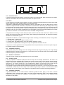
1
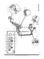
INSTRUCTIONS FOR USE
PHYACTION PERFORMA
Copyright© Uniphy BV 1995-98
Phyaction® is a registered trademark of Uniphy BV
Art. Code 93008021.5 EN
Phyaction is manufactured in the Netherlands by Uniphy BV
P.O. Box 558, NL-5600 AN Eindhoven, the Netherlands
Tel. +31 499 491800 Fax +31 499 474734
Your supplier is:
Contents
INTRODUCTION
CHAPTER 1
1.1
1.2
1.3
1.4
1.5
Electrical safety . . . . . .
Explosion safety . . . . . .
Safety in use . . . . . . . .
Use of the appliance . . .
Medical device directive
.
.
.
.
.
.
.
.
.
.
.
.
.
.
.
.
.
.
.
.
.
.
.
.
.
.
.
.
.
.
.
.
.
.
.
.
.
.
.
.
.
.
.
.
.
.
.
.
.
.
.
.
.
.
.
.
.
.
.
.
.
.
.
.
.
.
.
.
.
.
.
.
.
.
.
.
.
.
.
.
.
.
.
.
.
.
.
.
.
.
.
.
.
.
.
.
.
.
.
.
.
.
.
.
.
.
.
.
.
.
.
.
.
.
.
.
.
.
.
.
.
.
.
.
.
.
.
.
.
.
.
.
.
.
.
2
2
2
2
2
Check on delivery . . . . . . . . . . . . . . . . . . . . . . . . . .
Power voltage . . . . . . . . . . . . . . . . . . . . . . . . . . . . .
Functional test . . . . . . . . . . . . . . . . . . . . . . . . . . . .
Placing and transportation . . . . . . . . . . . . . . . . . . .
Fastening electrode arms and electrodes . . . . . . . .
Use of the high-frequency induction field indicator
.
.
.
.
.
.
.
.
.
.
.
.
.
.
.
.
.
.
.
.
.
.
.
.
.
.
.
.
.
.
.
.
.
.
.
.
.
.
.
.
.
.
.
.
.
.
.
.
.
.
.
.
.
.
.
.
.
.
.
.
.
.
.
.
.
.
.
.
.
.
.
.
.
.
.
.
.
.
.
.
.
.
.
.
.
.
.
.
.
.
.
.
.
.
.
.
.
.
.
.
.
.
.
.
.
.
.
.
.
.
.
.
.
.
.
.
.
.
.
.
.
.
.
.
.
.
.
.
.
.
.
.
.
.
.
.
.
.
.
.
.
.
.
.
.
.
.
.
.
.
.
.
.
.
.
.
3
3
3
3
3
6
.
.
.
.
.
.
.
.
.
.
.
.
.
.
.
.
.
.
.
.
.
.
.
.
.
.
.
.
.
.
.
.
.
.
.
.
.
.
.
.
.
.
.
.
.
.
.
.
.
.
.
.
.
.
7
7
7
7
7
7
7
7
7
7
8
8
8
8
8
8
8
8
8
8
9
9
9
9
9
9
9
.
.
.
.
.
.
.
.
10
10
11
12
CHAPTER 2
2.1
2.2
2.3
2.4
2.5
2.6
CHAPTER 3
3.1
3.2
3.3
3.4
3.5
3.6
3.7
3.8
3.9
3.10
3.11
3.12
3.13
3.14
3.15
3.16
3.17
3.18
3.19
3.20
3.21
3.22
3.23
3.24
3.25
3.26
3.27
.
.
.
.
.
.
.
.
.
.
.
.
.
.
.
.
.
.
.
.
.
.
.
.
.
.
.
.
.
.
.
.
.
.
.
.
.
.
.
.
.
.
.
.
.
.
.
.
.
.
.
.
.
.
.
.
.
.
.
.
.
.
.
.
.
.
.
.
.
.
.
.
.
.
.
.
.
.
.
.
.
.
.
.
.
.
.
.
.
.
.
.
.
.
.
.
.
.
.
.
INSTALLATION
EXPLANATION OF THE OPERATING MECHANISMS
Mains switch . . . . . . . . . . . . . . . . . . . . .
Selector key channel A . . . . . . . . . . . . . .
Selector key channel B . . . . . . . . . . . . . .
Selector key for pulse length . . . . . . . . .
Channel A pulse length display . . . . . . .
Channel B pulse length display . . . . . . .
Pulse repeat frequency selector key . . . .
Pulse repeat frequency display . . . . . . .
Peak output selector key . . . . . . . . . . . .
Average output selector key . . . . . . . . . .
Channel A output display . . . . . . . . . . . .
Channel B output display . . . . . . . . . . . .
Treatment time selector key . . . . . . . . . .
Treatment time display . . . . . . . . . . . . . .
Adjustment regulator . . . . . . . . . . . . . . .
Start/stop key . . . . . . . . . . . . . . . . . . . . .
Start/stop indicator lamp . . . . . . . . . . . .
Emitter A connection . . . . . . . . . . . . . . .
Emitter B connection . . . . . . . . . . . . . . .
Fixing points for electrode arms . . . . . . .
Electrode arm . . . . . . . . . . . . . . . . . . . . .
Circuplode . . . . . . . . . . . . . . . . . . . . . . .
Mains entry port with mains fuses . . . . .
Connection for potential equalizing cable
Model specification plate . . . . . . . . . . . .
Undercarriage with swivel castors . . . . .
Ventilation openings . . . . . . . . . . . . . . . .
CHAPTER 4
4.1
4.2
4.3
4.4
SAFETY ASPECTS
.
.
.
.
.
.
.
.
.
.
.
.
.
.
.
.
.
.
.
.
.
.
.
.
.
.
.
.
.
.
.
.
.
.
.
.
.
.
.
.
.
.
.
.
.
.
.
..
..
..
.
.
.
.
.
.
.
.
.
.
.
.
.
.
.
.
.
.
.
.
.
.
.
.
.
.
.
.
.
.
.
.
.
.
.
.
.
.
.
.
.
.
.
.
.
.
.
.
.
.
.
.
.
.
.
.
.
.
.
.
.
.
.
.
.
.
.
.
.
.
.
.
.
.
.
.
.
.
.
.
.
.
.
.
.
.
.
.
.
.
.
.
.
.
.
.
.
.
.
.
.
.
.
.
.
.
.
.
.
.
.
.
.
.
.
.
.
.
.
.
.
.
.
.
.
.
.
.
.
.
.
.
.
.
.
.
.
.
.
.
.
.
.
.
.
.
.
.
.
.
.
.
.
.
.
.
.
.
.
.
.
.
.
.
.
.
.
.
.
.
.
.
.
.
.
.
.
.
.
.
.
.
.
.
.
.
.
.
.
.
.
.
.
.
.
.
.
.
.
.
.
.
.
.
.
.
.
.
.
.
.
.
.
.
.
.
.
.
.
.
.
.
.
.
.
.
.
.
.
.
.
.
.
.
.
.
.
.
.
.
.
.
.
.
.
.
.
.
.
.
.
.
.
.
.
.
.
.
.
.
.
.
.
.
.
.
.
.
.
.
.
.
.
.
.
.
.
.
.
.
.
.
.
.
.
.
.
.
.
.
.
.
.
.
.
.
.
.
.
.
.
.
.
.
.
.
.
.
.
.
.
.
.
.
.
.
.
.
.
.
.
.
.
.
.
.
.
.
.
.
.
.
.
.
.
.
.
.
.
.
.
.
.
.
.
.
.
.
.
.
.
.
.
.
.
.
.
.
.
.
.
.
.
.
.
.
.
.
.
.
.
.
.
.
.
.
.
.
.
.
.
.
.
.
.
.
.
.
.
.
.
.
.
.
.
.
.
.
.
.
.
.
.
.
.
.
.
.
.
.
.
.
.
.
.
.
.
.
.
.
.
.
.
.
.
.
.
.
.
.
.
.
.
.
.
.
.
.
.
.
.
.
.
.
.
.
.
.
.
.
.
.
.
.
.
.
.
.
.
.
.
.
.
.
.
.
.
.
.
.
.
.
.
.
.
.
.
.
.
.
.
.
.
.
.
.
.
.
.
.
.
.
.
.
.
.
.
.
.
.
.
.
.
.
.
.
.
.
.
.
.
.
.
.
.
.
.
.
.
.
.
.
.
.
.
.
.
.
.
.
.
.
.
.
.
.
.
.
.
.
.
.
.
.
.
.
.
.
.
.
.
.
.
.
.
.
.
.
.
.
.
.
.
.
.
.
.
.
.
.
.
.
.
.
.
.
.
.
.
.
.
.
.
.
.
.
.
.
.
.
.
.
.
.
.
.
.
.
.
.
.
.
.
.
.
.
.
.
.
.
.
.
.
.
.
.
.
.
.
.
.
.
.
.
.
.
.
.
.
.
.
.
.
.
.
.
.
.
.
.
.
.
.
.
.
.
.
.
.
.
.
.
.
.
.
.
.
.
.
.
.
.
.
.
.
.
.
.
.
.
.
.
.
.
.
.
.
.
.
.
.
.
.
.
.
.
.
.
.
.
.
.
.
.
.
.
.
.
.
.
.
.
.
.
.
.
.
.
.
.
.
.
.
.
.
.
.
.
.
.
.
.
.
.
.
.
.
.
.
.
.
.
.
.
.
.
.
.
.
.
.
.
.
.
.
.
.
.
.
.
.
.
.
.
.
.
.
.
.
.
.
.
.
.
.
.
.
.
.
.
.
.
.
.
.
.
.
.
.
.
.
.
.
.
.
.
.
.
.
.
.
.
.
.
.
.
.
.
.
.
.
.
.
.
.
.
.
.
.
.
TREATMENT ASPECTS AND SETTING SEQUENCE
Introduction . . . . . . . . . . . . . .
Measures to be taken BEFORE
Measures DURING treatment .
Measures AFTER treatment . .
........
treatment
........
........
.
.
.
.
.
.
.
.
.
.
.
.
.
.
.
.
.
.
.
.
.
.
.
.
.
.
.
.
.
.
.
.
.
.
.
.
.
.
.
.
.
.
.
.
.
.
.
.
.
.
.
.
Contents - Instructions for use Phyaction Performa
.
.
.
.
.
.
.
.
.
.
.
.
.
.
.
.
.
.
.
.
.
.
.
.
.
.
.
.
.
.
.
.
.
.
.
.
.
.
.
.
.
.
.
.
.
.
.
.
.
.
.
.
.
.
.
.
.
.
.
.
.
.
.
.
.
.
.
.
.
.
.
.
.
.
.
.
CHAPTER 5
5.1
5.2
5.3
5.4
5.5
5.6
Introduction . . . . . . .
Dosage . . . . . . . . . . .
Treatment frequency .
Number of treatments
Contact control . . . . .
Treatment guidelines
CHAPTER 6
6.1
6.2
6.3
6.4
6.5
6.6
.
.
.
.
.
.
.
.
.
.
.
.
.
.
.
.
.
.
.
.
.
.
.
.
.
.
.
.
.
.
.
.
.
.
.
.
.
.
.
.
.
.
.
.
.
.
.
.
.
.
.
.
.
.
.
.
.
.
.
.
.
.
.
.
.
.
.
.
.
.
.
.
.
.
.
.
.
.
.
.
.
.
.
.
.
.
.
.
.
.
.
.
.
.
.
.
.
.
.
.
.
.
.
.
.
.
.
.
.
.
.
.
.
.
.
.
.
.
.
.
.
.
.
.
.
.
.
.
.
.
.
.
.
.
.
.
.
.
.
.
.
.
.
.
.
.
.
.
.
.
.
.
.
.
.
.
.
.
.
.
.
.
.
.
.
.
.
.
.
.
.
.
.
.
.
.
.
.
.
.
.
.
.
.
.
.
.
.
.
.
.
.
.
.
.
.
.
.
.
.
.
.
.
.
.
.
.
.
.
.
.
.
.
.
.
.
.
.
.
.
.
.
.
.
.
.
.
.
.
.
.
.
.
.
.
.
.
.
.
.
.
.
.
.
.
.
.
.
.
.
.
.
.
.
.
.
.
.
.
.
.
.
.
.
.
.
.
.
.
.
.
.
.
.
.
.
.
.
.
.
.
.
.
.
.
.
.
.
13
13
15
15
15
15
BASIC DATA ON SHORT-WAVE THERAPY
.
.
.
.
.
.
.
.
.
.
.
.
.
.
.
.
.
.
.
.
.
.
.
.
.
.
.
.
.
.
.
.
.
.
.
.
.
.
.
.
.
.
.
.
.
.
.
.
.
.
.
.
.
.
.
.
.
.
.
.
.
.
.
.
.
.
.
.
.
.
.
.
.
.
.
.
.
.
.
.
.
.
.
.
.
.
.
.
.
.
.
.
.
.
.
.
.
.
.
.
.
.
.
.
.
.
.
.
.
.
.
.
.
.
.
.
.
.
.
.
.
.
.
.
.
.
.
.
.
.
.
.
.
.
.
.
.
.
.
.
.
.
.
.
.
.
.
.
.
.
.
.
.
.
.
.
.
.
.
.
.
.
.
.
.
.
.
.
.
.
.
.
.
.
.
.
.
.
.
.
.
.
.
.
.
.
.
.
.
.
.
.
.
.
.
.
.
.
.
.
.
.
.
.
.
.
.
.
.
.
17
17
17
18
19
19
.
.
.
.
.
.
.
.
.
.
.
.
.
.
.
.
.
.
.
.
.
.
.
.
.
.
.
.
.
.
.
.
.
.
.
.
.
.
.
.
.
.
.
.
.
.
.
.
.
.
.
.
.
.
.
.
.
.
.
.
.
.
.
.
.
.
.
.
.
.
.
.
.
.
.
.
.
.
.
.
.
.
.
.
.
.
.
.
.
.
.
.
.
.
.
.
20
20
20
20
21
22
EFFECTS OF SHORT-WAVE THERAPY
Introduction . . . . . . . . . . . . . . . . . . . . . . . . . . . . . . . . .
Reactions to heat . . . . . . . . . . . . . . . . . . . . . . . . . . . . .
Thermal effects . . . . . . . . . . . . . . . . . . . . . . . . . . . . . . .
Athermal effects . . . . . . . . . . . . . . . . . . . . . . . . . . . . .
Influence of electromagnetic energy on wound healing
Specific effect on soft-tissue lesions . . . . . . . . . . . . . .
CHAPTER 8
8.1
8.2
8.3
.
.
.
.
.
.
Introduction . . . . . . . . . . . . . . . . . . . . .
Generation of the electromagnetic field
The Circuplode conductivity method . .
Penetration depth . . . . . . . . . . . . . . . .
Dissipation . . . . . . . . . . . . . . . . . . . . . .
Specific absorption rate (SAR) . . . . . . .
CHAPTER 7
7.1
7.2
7.3
7.4
7.5
7.6
PARAMETERS OF SHORT-WAVE THERAPY AND
TREATMENT GUIDELINES
.
.
.
.
.
.
.
.
.
..
.
.
.
.
.
.
.
.
.
.
.
.
.
.
.
.
.
.
.
.
.
.
.
.
.
.
.
.
.
.
INDICATIONS AND CONTRA-INDICATIONS
Indications . . . . . . . . . . . . . . . . . . . . . . . . . . . . . . . . . . . . . . . . . . . . . . . . . . . . . . . . . 23
Absolute contra-indications . . . . . . . . . . . . . . . . . . . . . . . . . . . . . . . . . . . . . . . . . . . . 23
Relative contra-indications . . . . . . . . . . . . . . . . . . . . . . . . . . . . . . . . . . . . . . . . . . . . . 23
CHAPTER 9
EXAMPLES OF TREATMENT
CHAPTER 10
FAULTS, GUARANTEE AND MAINTENANCE
10.1
10.2
10.3
10.4
10.5
10.6
10.7
Faults . . . . . . . . . . . . . . . . . .
Replacing the mains fuses .
Guarantee and service . . . . .
Cleaning . . . . . . . . . . . . . . .
Maintenance . . . . . . . . . . . .
Disinfection and sterilization
Technical maintenance . . . .
CHAPTER 11
11.1
11.2
.
.
.
.
.
.
.
.
.
.
.
.
.
.
.
.
.
.
.
.
.
.
.
.
.
.
.
.
.
.
.
.
.
.
.
.
.
.
.
.
.
.
.
.
.
.
.
.
.
.
.
.
.
.
.
.
.
.
.
.
.
.
.
.
.
.
.
.
.
.
.
.
.
.
.
.
.
.
.
.
.
.
.
.
.
.
.
.
.
.
.
.
.
.
.
.
.
.
.
.
.
.
.
.
.
.
.
.
.
.
.
.
.
.
.
.
.
.
.
.
.
.
.
.
.
.
.
.
.
.
.
.
.
.
.
.
.
.
.
.
.
.
.
.
.
.
.
.
.
.
.
.
.
.
.
.
.
.
.
.
.
.
.
.
.
.
.
.
.
.
.
.
.
.
.
.
.
.
.
.
.
.
.
.
.
.
.
.
.
.
.
.
.
.
.
.
.
.
.
.
.
.
.
.
.
.
.
.
.
.
.
.
.
.
.
.
.
.
.
.
.
.
.
.
.
.
.
.
.
.
.
.
.
.
.
.
.
.
.
.
.
.
.
.
.
.
.
.
.
.
.
.
.
.
.
.
.
.
.
.
.
.
.
.
.
.
.
.
.
.
.
.
.
.
.
.
.
.
.
.
.
.
.
.
.
.
.
27
27
27
28
28
28
28
TECHNICAL SPECIFICATIONS
ACCESSORIES
Standard accessories . . . . . . . . . . . . . . . . . . . . . . . . . . . . . . . . . . . . . . . . . . . . . . . . . 30
Optional accessories . . . . . . . . . . . . . . . . . . . . . . . . . . . . . . . . . . . . . . . . . . . . . . . . . 30
CHAPTER 13
13.1
13.2
.
.
.
.
.
.
.
Specifications . . . . . . . . . . . . . . . . . . . . . . . . . . . . . . . . . . . . . . . . . . . . . . . . . . . . . . . 29
Technical data . . . . . . . . . . . . . . . . . . . . . . . . . . . . . . . . . . . . . . . . . . . . . . . . . . . . . . 29
CHAPTER 12
12.1
12.2
.
.
.
.
.
.
.
EXPLANATION OF THE SYMBOLS
Symbols on the front of the appliance . . . . . . . . . . . . . . . . . . . . . . . . . . . . . . . . . . . . 31
Symbols on the model plate . . . . . . . . . . . . . . . . . . . . . . . . . . . . . . . . . . . . . . . . . . . . 31
BIBLIOGRAPHY
Contents - Instructions for use Phyaction Performa
Contents - Instructions for use Phyaction Performa
INTRODUCTION
You have selected the Phyaction Performa, Uniphy’s short-wave therapy appliance. Many congratulations on
your purchase. We are convinced that the Performa will serve you for many years in the treatment of a great
many symptoms.
The Phyaction Performa is an appliance used in pulsating short-wave therapy, whereby the various parameters
can be set in a simple and orderly manner.
This manual should not only been seen as an instruction manual for the appliance, but also as a work of
reference covering various aspects of short-wave therapy. The first four chapters provide information on the
various safety aspects, installation, operating mechanisms and methods for adjustment. Chapters 5 to 9 will
be of interest to those interested in the theory of short-wave therapy; basic data, effects, explanation of the
various parameters, indications and contra-indications. In chapter 10, practical applications for short-wave
therapy are shown for a number of indications.
If you have any questions or comments, we would be glad to hear from you. Our physiotherapists are always
ready to help you.
We wish you every success with the therapy!
Uniphy BV
February 2004
INTRODUCTION
Instructions for use Phyaction Performa - Page 1
CHAPTER 1
SAFETY ASPECTS
1.1 Electrical safety
The appliance may only be used in areas containing facilities which comply with current legal requirements.
Pay particular attention to the use of the earth connection, as otherwise the patient’s leakage current will
exceed the permitted limit for BF-type appliance.
1.2 Explosion safety
The appliance is not suitable for use in areas where inflammable gases or fumes are present. Therefore,
remove the plug from the socket before disinfecting the area in which the appliance is located, as some
disinfectants evaporate to form an explosive mixture.
1.3 Safety in use
- Metal parts can cause concentrations of intensity in the high-frequency field. This applies both to implanted
metal objects and objects which the patient is carrying and which are located close to the applicator. The
standard minimum distance is 1 metre from the applicator. See paragraph 4.2.
- Patients with a pacemaker may not be treated. Patients implanted with other electronic equipment may
receive short-wave therapy, as long as sufficient care is taken. If there is any doubt, consult a doctor. See
paragraph 4.2.3.
- The appliance is not suitable for use in wet areas.
- The appliance must not be disinfected or sterilised.
- Each time the appliance is switched on (with the main switch) an automatic test is carried out.
- The Circuplode(s), including the cable and plug, must be checked regularly for damage.
- Using this appliance in the proximity of another high-frequency electrotherapy appliance can affect the
correct operation of the appliance.
- The proper and safe operation of the device can only be guaranteed if it is used with the standard and/or
optional accessories as mentioned in these operating instructions (see chapter 12, ACCESSORIES).
- In order to safeguard the long-term safety of the device, we advise you to have a technical safety check
of the device and the accessories performed at least once every year.
1.4 Use of the appliance
The appliance and accessories must be used solely by qualified persons (trained in the application of shortwave therapy) in accordance with all the requirements included in this manual.
The Phyaction Performa must be used solely for providing short-wave therapy.
The temperature range for the use of the Phyaction Performa ranges from +10°C to +40°C. The temperature
range for storage and transport of the device ranges from -20°C to +70°C.
1.5 Medical device directive
This device complies with the essential requirements of the Medical Device Directive of the European
Committee (93/42/EEC).
For information on manufacturer’s liability, see chapter 10, FAULTS, GUARANTEE, MAINTENANCE.
1. SAFETY ASPECTS
Instructions for use Phyaction Performa - Page 2
CHAPTER 2
INSTALLATION
2.1 Check on delivery
Check that the appliance, the electrode arm(s) and the conductivity electrode(s) were not damaged during
transport, and that the accessories are intact and complete (see chapter 12 ACCESSORIES). In the event of
damage and/or missing parts, contact your supplier.
2.2 Power voltage
Your appliance is suitable for a nominal power voltage of 110-120 or 220-240 Volt AC, 50-60 Hz. The model
plate on the reverse of the appliance indicates the power voltage for which your appliance is wired. You cannot
change this yourself. Check this data carefully before putting the plug in the socket. The mains entry port is
located on the back of the appliance.
2.3 Functional test
The appliance is tested during production for electrical safety. Each time the appliance is switched on, the
processor carries out a two-second safety test to assess whether the appliance is functioning correctly. You
must check whether all the displays and lamps light up. After the test has been completed, you will hear a
buzzing sound, and the appliance can be operated.
If a fault is detected during treatment, this is indicated on the display by lines (--). The appliance will no longer
operate. See paragraph 10.1.
2.4 Placing and transportation
Read chapter 1 on Safety Aspects before you use the Phyaction Performa for the first time. Ensure that the
appliance is horizontal and stable. Do not place the appliance close to heat sources such as radiators or hotair grids and avoid leaving the appliance for long periods of time in direct sunlight. Ensure that the ventilation
grilles on the back of the appliance are not covered, so that air can circulate freely. Do not place any objects
on the appliance, and ensure that no liquids are spilled into the appliance. If any liquids or foreign objects do
enter the housing, switch off the appliance immediately, remove the plug from the socket and contact your
supplier to have the appliance inspected before using it again.
We would like to emphasise the fact that the Circuplodes must be handled very carefully.
We also recommend that you avoid using the Phyaction Performa immediately after extreme temperature
changes.
2.5 Fastening electrode arms and electrodes
On the last page of this instruction manual you will find a drawing showing the appliance and accessories. The
numbers in the text correspond to the numbers in this drawing.
Thanks to their special construction, the Phyaction Performa’s conductivity electrodes are known as
Circuplodes.
2.5.1 Assembly
The electrode arm(s)23 must be mounted in the correct manner on the back of the cabinet. See figure 1. If
necessary, use the crosshead screwdriver supplied to mount the arms.
2. INSTALLATION
Instructions for use Phyaction Performa - Page 3
Figure 1. Fastening the electrode arm(s)
2.5.2 Adjusting the electrode arms
Figures 2 to 6 show how the various joints of the arms can be adjusted, if necessary. The fixing points of the
arms must be adjusted in such a way that the arms can be properly fixed in placed by hand-tightening the
black fixing-knob24. For adjustment, use the heaviest electrode only with the arms set at the position shown
in figure 2. Use the box spanners supplied.
Figure 2.
2. INSTALLATION
Figure 3.
Instructions for use Phyaction Performa - Page 4
Figure 4.
Figure 5.
Figure 6.
2.5.3 Composition of fixing system
Figure 7 shows the composition of the fixing system. The black fixing-knob24 is mounted as standard on the
front of the arm. If required, it can also be mounted on the back.
Figure 7.
2. INSTALLATION
Instructions for use Phyaction Performa - Page 5
2.5.4 Electrode fastening
The electrodes26 are inserted into the opening at the end of the electrode arms, and fixed in place using the
black knob27. See figure 8.
Figure 8.
2.5.5 Connecting the electrode cable(s)
On one side, the electrode cable is connected to the Circuplode by means of two identical bayonet connectors,
and on the other side connected to the connection18,21 on the back of the appliance. Then fix the cable in the
channel of the cable guide28, which is fixed halfway along the electrode arm. This prevents the cable touching
a patient or another cable, which could concentrate the electromagnetic output.
2.6 Use of the high-frequency induction field indicator
Included as standard with the Phyaction Performa is an indicator which can make the high-frequency induction
field visible to both you and your patient. To do this, hold the indicator against the active Circuplode, making
sure, in connection with the contact check, that at least 50% of the electrode surface is covered by your hand,.
As soon as the dosage is increased and output flows from the appliance, the yellow LED on the indicator lights
up. The LED glows brighter as the output increases. At low frequencies, the LED will blink.
2. INSTALLATION
Instructions for use Phyaction Performa - Page 6
CHAPTER 3
EXPLANATION OF THE OPERATING MECHANISMS
On the last page of this instruction manual you will find a drawing showing the appliance and accessories. The
numbers in the text correspond with the numbers in this drawing.
3.1 Mains switch
The mains switch1 on the top of the front side of the appliance is used to switch the Phyaction Performa on
and off.
Switching on: press the key to the right (I).
Switching off: press the key to the left (0).
3.2
Selector key channel A
After pressing the selector key2 for channel A, the green lamp in the key lights up. You can now
set the parameters for channel A.
3.3
Selector key channel B
After pressing the selector key3 for channel B, the green lamp in the key lights up. You can now
set the parameters for channel B.
3.4
Selector key for pulse length
After pressing the selector key for pulse length4 the green lamp in the key lights up. Pressing this
key links the adjustment regulator15 to the pulse length parameter for channel A or channel B. The
pulse length can now be set between 65 and 400 µs and is shown on the display5 for A or the
display6 for B.
3.5 Channel A pulse length display
This display5 shows the pulse length for channel A in microseconds. The pulse length can be set by selecting
channel A and pressing key4.
3.6 Channel B pulse length display
This display6 shows the pulse length for channel B in microseconds. The pulse length can be set by selecting
channel B and pressing key4. The display will not light up if channel B is not connected.
3.7
Pulse repeat frequency selector key
After pressing the pulse repeat frequency selector key7 the green lamp in the key lights up. Pressing
this key links the adjustment regulator to the pulse repeat frequency parameter of both channel A
and channel B. The frequency can now be set between 26 and 400 Hz, in ten steps, and can be
read on the display8.
3.8 Pulse repeat frequency display
The pulse repeat frequency display8 shows the pulse repeat frequency for both channels. When this is set for
channel A, for example, it is also adopted by channel B.
3.9
Peak output selector key
After the peak output selector key9 is pressed, the green lamp in the key lights up. Pressing this key
causes the peak output to be shown on displays11 and 12. The peak output of the large Circuplode
(diameter 14 cm) can be set between 0 and 200 Watt, and of the small Circuplode (diameter 9 cm)
between 0 and 100 Watt.
If the lamp flashes on and off, this indicates that the peak output is being shown on the display while the key9
is not pressed in.
3.10 Average output selector key
After this key10 is pressed, the green lamp in the key lights up. Pressing this key causes the average output
to be shown on display11 and display12. This also links the adjustment regulator to the output parameter. The
3. EXPLANATION OF THE OPERATING MECHANISMS
Instructions for use Phyaction Performa - Page 7
average output for the large Circuplode can be set between 0 - 32 Watt and the small Circuplode
between 0 - 16 Watt.
If the lamp flashes on and off, this indicates that the peak output is being shown on the display
while the key10 is not pressed in.
3.11 Channel A output display
The display11 shows the peak or average output, depending on the choice of keys 9 or 10. During automatic
adjustment, the display will flash on and off. After switching on with key16 the display shows the actual output.
This can vary slightly from the values set in advance.
3.12 Channel B output display
This display will light up only if an electrode is connected to channel B. See 3.11 for further details.
3.13 Treatment time selector key
After the treatment time selector key13 is pressed, a green lamp in the key lights up. This links the
adjustment regulator to the treatment time parameter. Treatment time can now be set in minutes,
and can be read on display14. Treatment can only start once the treatment time has been set.
3.14 Treatment time display
The treatment time display14 shows the set treatment time or the remaining treatment time. Treatment time
is the same for both channels. Between 0 and 10 minutes, the time is displayed in half minutes, between 10
and 30 minutes it is displayed in whole minutes.
When the timer is operational, this is shown by a flashing dot on the display. In the event of insufficient
contact, treatment is interrupted and the treatment timer stops.
At the end of the treatment time, a buzzer will sound for 4 seconds, and the output is returned to 0 Watt.
3.15 Adjustment regulator
All parameters are set with the adjustment regulator15: the regulator is linked to the parameter for which the
green lamp is lit.
To reduce the value, turn the regulator to the left. To increase the value, turn the regulator to the right. The
regulator has no start or finish settings. The parameter value can be read off the appropriate display. The
adjustment range is determined by the parameter selected.
3.16 Start/stop key
When treatment is commenced, the lamp in the key goes green. It can only be started if a treatment
time has been set. Treatment can be stopped before the end of the treatment time by pressing the
start/stop key16 again. The output is then reduced to zero. The lamp in the key then lights up red.
3.17 Start/stop indicator lamp
During the automatic test when the appliance is switched on, the start/stop lamp17 lights up yellow.
If treatment has stopped or has not yet started, the lamp is red.
When treatment is started, the lamp lights up green.
3.18 Emitter A connection
The electrode cable20 is connected to this connection18 via the bayonet connection19. The length and
impedance of the cable are critical. For this reason, never use other commercially available cables.
Connecting any cable other than one supplied can jeopardise the patient’s safety and damage the
correct operation of the appliance, and is therefore prohibited.
3.19 Emitter B connection
For the connection of emitter B19 see 3.18.
3.20 Fixing points for electrode arms
The electrode arms are fixed to the fixing points22. For assembly details see paragraph 2.5.
3. EXPLANATION OF THE OPERATING MECHANISMS
Instructions for use Phyaction Performa - Page 8
3.21 Electrode arm
The electrode arm23 is connected to the fixing points22 Using the large black knob24, one of the joints of the
fixing system can be locked. At the end of the arm there is an opening25 in which the Circuplode26 can be
inserted. The Circuplode is locked in place by means of the small black knob27. The cable can be fitted into
the cable guide28 attached to the arm.
3.22 Circuplode
On the back of the Circuplode26 there is a connection29 to which the bayonet connection30 of the electrode
cable31 can be connected. You will also see a lamp32 which lights up green as soon as there is any electromagnetic output. During adjustment and in the event of insufficient contact, the lamp will flash on and off.
3.23 Mains entry port with mains fuses
The mains power cord34 (supplied) is connected to the mains entry port33. Here there are also two 6.3 A F
mains fuses (type G, 250 V). See paragraph 10.2 for instructions on replacing faulty fuses.
3.24 Connection for potential equalizing cable
A special earth cable can be supplied for use in areas for which a potential equalizing cable is required in
accordance with national installation standards, and connected to this connection35.
3.25 Model specification plate
The model specification plate36 shows appliance data such as the model and serial number (for service and
guarantee, etc.), as well as connection data such as mains voltage and measured power.
3.26 Undercarriage with swivel castors
The two wheels on the front of the undercarriage37 are fitted with foot-operated brakes; to block them, press
down the handle38, to release them, pull the handle up.
3.27 Ventilation openings
The ventilation openings39 in the housing allow the heat produced by the electronics to be expelled. It is
important that these openings are not covered.
3. EXPLANATION OF THE OPERATING MECHANISMS
Instructions for use Phyaction Performa - Page 9
CHAPTER 4
TREATMENT ASPECTS AND SETTING SEQUENCE
4.1 Introduction
This chapter deals with various measures which must be taken before, during and after treatment. For further
information on the theory of pulsating short-wave therapy and the parameters, we refer you to chapters 5
through 8. Before using this appliance for the first time, please read chapter 1, Safety Aspects, and chapter
2, Installation.
4.2 Measures to be taken BEFORE treatment
Chapter 8, Indications and Contra-indications, contains information essential for safe and effective treatment.
Before commencing treatment, ensure that there are no contra-indications.
4.2.1 Metal objects and furniture
Metal articles can cause concentrations of intensity in the high-frequency field. This applies both to metal
objects worn or carried by the patient and to objects in the close vicinity of the applicator. As a rule of thumb,
a minimum distance of 1 metre must be observed. Therefore, use only wooden, glued furniture.
During treatment, the patient must also not come into contact with any metal objects, such as radiators or
window frames.
4.2.2 Clothing and intervening substance
For all short-wave treatments, it is recommended that the patients remove their clothing, and that a towel be
placed between the skin and the electrode. The towel keeps both skin and applicator dry. It also prevents loss
of heat, promotes hygiene and ensures the patient’s privacy. Treating patients who are naked offers various
advantages: firstly, it is the easiest way to ensure that no metal objects are located in the high-frequency field
(metal in clothing, such as buttons, zips, or hidden jewellery, keys, etc.) Secondly, it also prevents undesired
concentrations of energy resulting from nylon, leather, damp sweaty clothing, ointment dressings, wet
dressings, etc.)
4.2.3 Implanted electronic devices
Patients with implanted electronic devices may be treated with short-wave therapy, as long as sufficient care
is taken (for example, patients with an implanted pacemaker must not be treated!) If in doubt, consult a doctor.
Electronic hearing aids must be removed, as these may be damaged by the electromagnetic radiation, or could
cause a fault to occur.
4.2.4 Implanted metals
Metal objects in the body, such as plates, pins, screws, a coil, pacemakers, etc., form a contra-indication. The
electrode must be placed at a distance of at least 1 metre from the implanted metal. In order to prevent
undesired concentrations around the metal and the dangers related to this (internal burns), short-wave therapy
resulting in a perceivable thermal effect should not be given.
4.2.5 Other points of attention
- The patients must receive clear instructions on what he or she may and/or must feel. Any unpleasant
sensations must be avoided.
- From the point of view of safety, use only the original. undamaged electrode cables and electrodes.
- Patients who have a reduced thermal sensitivity in the area to be treated must be treated with care. In
these cases, use only a low dosage and short treatment times.
- It may be necessary to carry out a check on the patient’s subjective experiences and for a doctor to carry
out an objective skin reaction check.
- Application on a treatment area which has been locally anaesthetized is strongly advised against.
4.2.6 Simultaneous use of other electronic equipment
The Phyaction Performa generates a high-frequency field at the legally permitted frequency of 27.12 MHz. This
field can affect the electronic circuits of equipment in the vicinity.
4. TREATMENT ASPECTS AND SETTING SEQUENCE
Instructions for use Phyaction Performa - Page 10
The sensitivity of equipment to high-frequency fields can vary greatly. This is because some manufacturers
do not adequately shield their equipment against high-frequency fields. If this occurs, we recommend that you
contact the manufacturer or supplier in question.
We recommend that you pay attention to the following points in order to reduce the chance high-frequency
interference to a minimum:
- Avoid simultaneous use of other electro-medical equipment in the direct vicinity of the appliance.
- Under the influence of electromagnetic output, electronic equipment can become damaged or break down.
This not only applies to electro-medical equipment, but also to audio-video appliances, watches, diskettes
and cashpoint cards, etc. This can only be completely prevented by installing a Faraday cage.
- The greater the distance between the short-wave appliance and other equipment, the lesser the chance
of high-frequency interference. Place the short-wave appliance and the patient at a distance of at least 1
metre from surrounding equipment and/or long metal objects.
- It is advisable that the short-wave appliance be connected to a separate power group.
- Ensure that the power cord of the short-wave appliance is kept out of the way of the patient and/or other
electrode cables or mains leads of other (electro-medical) equipment.
- Use a treatment chair or couch that is completely metal-free.
4.2.7 Measures regarding the appliance
- Ensure that all operating switches are set to zero.
- Electrode cables also emit an electromagnetic field. Ensure that the electrode cables do not come in
contact with the ground, with the patient or with each other. If contact is made, or nearly made, this results
in a high concentration of electromagnetic output, causing a great deal of heat. If a certain arrangement
does cause the cables to touch the patient or each other, a layer of felt at least 4 cm thick must be placed
on the point of contact as an intervening substance.
- Movement of the electrodes can be prevented by fixing them in place with Velcro.
4.3 Measures DURING treatment
An automatic test is always carried out every time the Phyaction Performa is switched on. See paragraph 2.3.
4.3.1 Setting sequence
For an explanation of the operating mechanisms, we refer you to chapter 3, EXPLANATION OF THE
OPERATING MECHANISMS.
The following parameters are set in sequence:
1.
It is possible to set the pulse length separately for channel A and channel B. Therefore it is
necessary to indicate which channel is to be set. Select Circuplode A or B with the appropriate
selector key. A green lamp lights up on the selector key pressed.
If no electrode is connected to channel A or B, the parameters in question cannot be set. Before
you can set the parameters, the Circuplode must be connected to the appliance.
On the back of the Phyaction Performa, near the connections for the electrode cables, there is
a sticker showing which connection is for channel A and which for channel B. If you are facing
the operating pad of the Phyaction Performa, the left connection is for channel A and the right
for channel B.
2.
Press the pulse length selector key to adjust the pulse length for the Circuplode selected. Set the
pulse length by turning the knob.
3.
Press the pulse frequency selector key to adjust the pulse frequency, then turn the knob to set
the required frequency.
4.
Pressing the peak output or average output key allows you to set the peak output or average
output for the selected Circuplode. The output can be then set by turning the knob.
4. TREATMENT ASPECTS AND SETTING SEQUENCE
Instructions for use Phyaction Performa - Page 11
5.
If you wish to execute an application using only one Circuplode, move straight on to point 6.
When applying two Circuplodes simultaneously, select the second electrode by pressing the
appropriate selector key after having carried out steps 1 to 4. Then set the pulse length and
output for the second Circuplode in the manner described above.
6.
Once all the parameters for one or both Circuplodes have been set, treatment time can be set
by pressing the treatment time selector key and setting the desired treatment time in minutes by
turning the knob.
Treatment can only commence once the treatment time has been set.
7.
Treatment can now be started by pressing the start/stop key, which causes the green lamp on
the key to light up. During the automatic tuning, the value on the output display flashes on and
off.
In order to ensure treatment quality, the contact control is switched on automatically if there is
insufficient contact. As soon as contact is restored, treatment is resumed.
8.
During treatment, the settings can be adjusted by the same method. We recommend that you do
not increase the intensity during treatment.
9.
After treatment is finished, you will hear a short bleeping sound and the output is reduced to zero.
The red light on the start/stop key lights up. The pulse length and frequency remain in view on
the displays. Treatment can also be terminated at any time by pressing the start/stop key.
4.3.2 Regarding the patient
During treatment, the therapist must regularly check the patient’s subjective heat sensation. Increased blood
flow can cause tissue temperature to increase. If there is insufficient blood circulation, this heat cannot be
adequately dispersed, which can result in thermal lesions.
If pain or muscle tension increase during treatment, the dosage should be reduced, for example by reducing
the pulse frequency.
4.4 Measures AFTER treatment
After treatment has finished, the electrode(s) should be removed and, if appropriate, the appliance switched
off.
4. TREATMENT ASPECTS AND SETTING SEQUENCE
Instructions for use Phyaction Performa - Page 12
CHAPTER 5
PARAMETERS OF SHORT-WAVE THERAPY AND
TREATMENT GUIDELINES
5.1 Introduction
In chapter 6, we discuss how the output of the electromagnetic field which penetrates the tissue is transformed
into heat by the currents generated. In practice, it is impossible to measure these heat increases, especially
when they are only very small. The patient can sense temperature changes in the skin. Deeper tissues do not
contain thermosensors. This means that we always have to rely on the patients’ subjective perceptions. This
is determinative for the dosage of the therapy, along with the nature and condition of the complaint, of course.
Athermal effects also cannot be measured in practice. The therapist must rely on clinical effects in the course
of time (such as changes in mobility, pain, swelling and temperature), which can be measured before, during
and after treatment.
For more extensive information on the theory of short-wave therapy, please turn to chapters 6, 7 and 8.
5.2 Dosage
A number of factors play a significant role in determining the dosage in short-wave therapy, and the therapist
has to make a choice for a specific setting. The following must be considered:
1. Circuplode format
2. Application with one or two Circuplodes simultaneously
3. Electrode placement
4. Pulse length
5. Pulse repeat frequency
6. Peak output or average output
7. Treatment time
8. Dose
These parameters are covered in sequence in the following paragraphs.
5.2.1 Circuplode format
The conductivity electrodes of the Phyaction Performa are known as ’Circuplodes’, thanks to their special
construction (see paragraph 6.3).
Two sizes of Circuplode can be used on the Phyaction Performa. A Circuplode with a 14 cm diameter is
supplied as standard. A smaller Circuplode with a 9 cm diameter is supplied as optional.
The smaller Circuplode can be used to treat small areas of the body. The electrode should be approximately
the same size as the part of the body to be treated. In addition to the difference in treatment surface area
between the two electrode formats, there is also a difference in peak output; the large Circuplode has a peak
output of 200 Watt, the smaller one has a peak output of 100 Watt. The Phyaction Performa automatically
recognises which format Circuplode is connected to which channel, and adapts the maximum output
immediately.
5.2.2 Application with two Circuplodes simultaneously
The Phyaction Performa offers the possibility of working with two Circuplodes simultaneously, whether or not
of the same format. Simultaneous use offers the following advantages:
- covering a large treatment area in one session;
- complaints on two sides can be treated simultaneously;
- one part of the body can be approached from two sides at once;
- a local and a segmental treatment can be given simultaneously.
If two Circuplodes are to be used simultaneously, the pulse length and output can be set for each Circuplode
individually. The pulse repeat frequency and treatment time selected are equal for both Circuplodes.
During simultaneous use, the two Circuplodes cannot weaken or strengthen the other, as the pulse of one
Circuplode is transmitted in the pulse pause of the other.
5. PARAMETERS AND TREATMENT GUIDELINES
Instructions for use Phyaction Performa - Page 13
5.2.3 Electrode placement
The Circuplode must be placed with the permeable screen aimed at the area of the body to be treated. In
order to ensure an optimum alignment, it is important that the electrode is not placed further than 1 cm away
from the part of the body to be treated. Direct contact with the area of the body, with a towel as an intervening
substance, is to be preferred. Above all, the part of the body to be treated must be large enough in relation
to the Circuplode to ensure a sufficient transfer of power.
As explained in paragraph 6.3, the effects of the Circuplode only take place around the edges, in other words
where the coils of the spool are located. Theoretically, there is no electromagnetic field in the middle of the
Circuplode, and virtually no heat will be generated there. The middle of the coil is therefore the least effective.
The Circuplodes must therefore be placed in such a way that the outside part of the coil affects that part of
the body where power dissipation is desired and can be expected.
5.2.4 Pulse length
The average output is the product of the peak output, pulse length and pulse repeat frequency.
The pulse length on the Phyaction Performa is adjustable in 7 steps from 65 - 400 µsec.
5.2.5 Pulse repeat frequency
The pulse repeat frequency on the Phyaction Performa is adjustable in 10 steps, ranging from 26 - 400 Hz.
For a given intensity and a variable pulse length, the pulse repeat frequency determines whether a cumulative
thermal effect can take place, causing the tissue temperature actually to increase. This process is dependent
partly on local blood circulation, and the extent to which it cools down the area. Figure 10 shows that if the
thermal effect can be equalized in the pulse pause, the temperature will not increase and no heat will be felt.
If a new impulse is given after the thermal effect has disappeared, a new thermal effect will occur, just as large
as the previous one, while the athermal effect is added to the athermal effects already present. Therefore, we
can see that summation is taking place.
Figure 9. Heat development during pulsing short-wave therapy A: no
measurable temperature increase
B: measurable temperature increase
5.2.6 Peak output or average output
The Phyaction Performa offers the therapist the choice of displaying the peak output or the average output.
Peak output Pp (Watt) refers to the size of the pulse in figure 10, in other words the intensity. The maximum
peak output of the large Circuplode (diameter 14 cm) is 200 Watt and of the smaller Circuplode (diameter 9
cm) is 100 Watt.
The average output P (Watt) is the product of the set peak output, the pulse length and the pulse frequency.
If you are interested in viewing the average output resulting from the settings, the output display can be set
to show the average output instead of the peak output.
The maximum average output of the large Circuplode is 32 Watt and the small Circuplode, 16 Watt.
5. PARAMETERS AND TREATMENT GUIDELINES
Instructions for use Phyaction Performa - Page 14
Figure 10. Pulse output (Pp) and average output (P)
5.2.7 Treatment times
In general, treatment times between 10 and 30 minutes are recommended. With normal blood circulation,
maximum vasodilation will have been achieved within this period of time.
5.2.8 Dose
For the application of pulsed electromagnetism, the dose of treatment is determined by the product of the peak
output, pulse length, pulse repeat frequency and treatment length.
The setting is implemented according to subjective criteria. If the patient can and may feel heat for a certain
indication, a subjective heat sensation by the patient is assumed when determining the dosage. When using
the Circuplode, most heat is generated in places where there are no thermosensors (in the muscles) and heat
sensation in the skin is relatively low. Therefore, the patient should certainly not feel any heat at the start of
treatment. Later on in the course of treatment, this is permissible, as the skin has been heated by the muscles
by means of conduction. The set dose must not be increased during treatment.
If the patient has no feeling in certain areas, the dose should be set and a test carried out in advance on the
healthy side where the patient does have feeling. When treating the affected side, the determined intensity
should then be decreased by 30%.
Schliephake has drawn up a system determining the dose according to the sensation of heat, in four grades:
1. submitis dose: no heat is felt;
2. mitis dose: the patient fells a slight sensation of heat;
3. normalis dose: the patient feels a clear and pleasant sensation of heat;
4. fortis dose: the patient feels a strong but, as yet not unpleasant sensation of heat.
If any pain or muscle hypertonia occur during treatment due to trophic disorder, the maximum peak output (or
the average output) must be reduced.
5.3 Treatment frequency
This depends partly on the dosage; with a low dosage, treatment can be given every day, with a high dosage
treatment frequency should be kept down to 1-3 times per week. The clinical results must indicate whether
treatment frequency must be changed.
5.4 Number of treatments
The total number of treatments is determined by the clinical results.
5.5 Contact control
It is very important to treatment quality that the set output is also actually transferred to the tissue. The
Phyaction Performa is equipped with an optical and acoustic contact control, which ensures optimum energy
transfer. If the power emitted deviates more than 10% from the set output, the Performa is automatically
switched off. The contact control led on the Circuplode then flashes, as does the power indicator on the
appliance. Above all, a pulsing acoustic signal sounds to indicate that contact should be restored.
It is important for good contact that the Circuplode is placed at not more than 1 cm from the part of the body
to be treated, and that the part of the body to be treated is large enough in relation to the Circuplode. Direct
contact with the part of the body to be treated is to be preferred, with a towel as intervening substance.
5.6 Treatment guidelines
A general distinction can be made between treatment guidelines which apply in the case of severe
inflammatory action, and those which apply in the case of mild inflammatory action. The parameter settings
indicated must only be used as a guideline, as the dosage is often dependent on the subjective heat
sensations of the patient.
5. PARAMETERS AND TREATMENT GUIDELINES
Instructions for use Phyaction Performa - Page 15
For further information on the various phases of the inflammation process, please see paragraph 7.5.
5.6.1 Severe inflammatory action
Severe inflammatory action is marked by pain during rest and/or movement during clinical examination.
Movement is restricted and strain capacity is reduced. The immune systems can be stimulated by stimulating
the athermal effects. This is achieved by setting a low average output with a high peak output, short pulse
lengths and a low pulse repeat frequency. Treatment lasts 10 to 20 minutes and is given daily or even several
times a day.
Possible parameter settings for a submitis dosage:
Pulse length
65 µs
Pulse repeating frequency
26 Hz
Treatment duration
10 minutes
Treatment frequency
daily
Peak output
200 Watt
Average output
0.34 Watt
5.6.2 Mild inflammatory action
Mild inflammatory action can be marked by pain during or after movement (particularly in an extreme position).
The tissues can be strained increasingly. The objective to "stimulate blood circulation" can be achieved during
the production phase by stimulating the thermal effects, for which the dosage is increased from mitis to
normalis. A high average output with a high peak output, long pulse time and high pulse repeat frequency is
set. Treatment lasts 20 to 30 minutes and is given 2 to 3 times a week.
Possible parameter settings for a mitis dosage:
Pulse length
150 µs
Pulse repeat frequency
110 Hz
Treatment duration
20 minutes
Treatment frequency
3 times a week
Peak output
200 Watt
Average output
3.30 Watt
Possible parameter setting for a normalis dosage:
Pulse length
300 µs
Pulse repeat frequency
200 Hz
Treatment duration
20 minutes
Treatment frequency
3 times a week
Peak output
200 Watt
Average output
12 Watt
During the remodelling phase, a fortis dosage can be administered during treatment:
Possible parameter settings for a fortis dosage:
Pulse length
400 µs
Pulse repeat frequency
300 Hz
Treatment duration
30 minutes
Treatment frequency
once a week
Peak output
200 Watt
Average output
24 Watt
5. PARAMETERS AND TREATMENT GUIDELINES
Instructions for use Phyaction Performa - Page 16
CHAPTER 6
BASIC DATA ON SHORT-WAVE THERAPY
6.1 Introduction
High-frequency electrotherapy is the medical treatment which uses electromagnetic fields with a vibration
frequency higher than 300 KHz. Nerve tissue is no longer depolarized at such high frequencies, but heat is
generated by the conversion of electromagnetic output. A number of specific frequencies are used in
physiotherapy, ie., 27.12 MHz, 433.92 MHz and 2450 MHz.
The Phyaction Performa is a device used for high-frequency electromagnetic therapy in which the
electromagnetic energy is generated at a frequency of 27.12 MHz. The wavelength in vacuum of this frequency
is 11.06 metres, so that it is sometimes referred to as the 11 metre wave therapy or short-wave therapy.
In the Phyaction Performa, electromagnetic energy is emitted in pulses. The therapist can regulate the pulse
length and the pulse repeating frequency according to the desired therapeutic effect.
6.2 Generation of the electromagnetic field
Energy is transferred from the source to the surrounding area in the electromagnetic field that is generated
by the Phyaction Performa. Live tissues are influenced by the action of electromagnetic force on tissue
molecules and ions. Electric and magnetic fields can distinguished: in the electric field, electrical energy is
exerted on charged particles, and in the magnetic field this is magnetic energy. As the electrical force is much
stronger than the magnetic force, only the electric component affects live tissue.
There are two ways of generating the electric field in short-wave therapy: by means of condensor field
electrodes (condensor method) or by means of choking-field electrodes (conductivity method). The electrodes
are insulated in both methods which makes conductive contact with skin impossible.
As the conductivity method is used in most cases, this is the only application available on the Phyaction
Performa. The method will be discussed in greater detail below.
6.3 The Circuplode conductivity method
The choking-field electrode is flat spiral spool inside a metal casing. The electromagnetic force does not have
any effect on the electrode’s insulation material. The patient’s body can never make contact with the conductor
metal so that there is no risk of burning.
Figure 11. An example of a Circuplode
Figure 12 shows that in the conductivity method the electric field close to the spool is relatively strong and is
aligned according to the spool’s loops. The strength of the electric field on the spool’s axis (also known as the
radial electric field) is minimal.
6. BASIC DATA SHORT-WAVE THERAPY
Instructions for use Phyaction Performa - Page 17
Figure 12. Alignment pattern and relative strength distribution of the
magnetic field component in circular spool winding (A) and of the
electrical field component (B)
The electrodes supplied with the Phyaction Performa are called "Circuplodes" because of their special
construction which allows the circular electric field through at the front and parallel to the spool so that circular
flows are generated parallel to the tissue layers. In contrast to "normal" electrodes, the radial electric field
component is suppressed in the Circuplodes. It has been demonstrated that an electric field penetrates tissues
better with an electric field that is parallel to the tissue layers (therefore the circular electric field) than an
electric field which is at right angles to the tissue layers (the radial electric field).
At 27 MHz the maximum Specific Absorption Rate SAR (see paragraph 6.6 of this chapter) in the skin/fat layer
in the radial electric field is about ten times greater than in the muscle layer so that heat development is very
superficial. On the other hand, the maximum SAR in the parallel electric field is greatest in the muscle layer,
even up to twenty or thirty times greater than in the skin/fat layer. Therefore heat development is no longer
superficial.
Thus the effective area is ring-shaped, and this should be taken into account when the electrodes are put in
place.
6.4 Penetration depth
The penetration depth is the distance across which the field is weakened by a factor of 0.37 (therefore where
37% remains).
Table 1 shows that both the wavelength and penetration depth decrease as the frequency increases and both
are greater in fatty tissue than in muscle tissue.
The figures in the table must be treated circumspectly and are only provided to give you an impression. After
all, they apply to separate tissues and when "flat" waves are used. In reality we deal with successive layers
of tissues and therefore these figures do not apply in practice.
wavelength (m)
penetration depth (m)
Frequency
(MHz)
muscle
fat
air
muscle
fat
27
(100)
434
(915)
2450
0.66
0.27
0.084
0.043
0.017
2.05
0.81
0.26
0.13
0.050
11.1
3.00
0.69
0.33
0.12
0.13
0.065
0.031
0.026
0.017
0.58
0.25
0.12
0.088
0.064
Table 1. Wavelength and penetration depth in muscle and fatty tissue using a number of frequencies.
6. BASIC DATA SHORT-WAVE THERAPY
Instructions for use Phyaction Performa - Page 18
6.5 Dissipation
The energy of the electromagnetic field which penetrates the tissues is converted into heat by the flows
generated by it; this is known as dissipation. The degree of increase in local temperature is limited and
depends on the dosage, the type of tissue and heat dispersal, which in turn depends on the extent of the
vasculated tissue. The heat is dispersed to the environment by means of heat conductivity, as long is this
environment is cooler.
It is important to realize that increasing temperature in the deeper tissues cannot be sensed, whereas of an
increase in skin temperature can be sensed due to the presence of thermosensors.
Where dissipation takes place in the tissues depends on the frequency used (27.12 MHz in the case of the
Phyaction Performa) and type of treatment. It is possible to heat structures such as muscles that are good heat
conductors with the conductivity method using the specially constructed Circuplode, without the skin and fatty
tissue increasing significantly in temperature or any sensation of heat.
The amplitude of the electric field strength decreases owing to dissipation.
6.6 Specific absorption rate (SAR)
High-frequency electromagnetic energy is converted into heat in the body. The amount of energy that can be
dissipated by tissue per time unit (the energy) is indicated by the SAR (Specific Absorption Rate). The energy
(Joules) leads to an increase in temperature.
The SAR can be calculated using the following formula:
SAR = (0.5σ E2)/p (Watt/kg)
σ = the specific electrical conductivity of the tissue
E = the local electric field strength amplitude
ρ = the specific mass density
For muscle tissue ρ = 1070 kg/m3
For fatty tissue ρ = 940 kg/m3
SAR varies from one place to the next in the body because E depends on the site. For this reason, indicating
the maximum SAR which occurs somewhere in the tissues in any given situation will suffice in practice.
Table 2 shows that conductivity σ of tissues becomes greater when the frequency increases. It also shows
that the conductivity of muscle tissues is ten times greater than that of fatty tissue. The local strength of the
electric field E depends on the type and position of the source.
Frequency
(MHz)
27
(100)
434
(915)
2450
Specific conductivity (S/m)
fat
muscle
0.05
0.08
0.12
0.15
0.21
0.6
0.9
1.4
1.6
2.2
Table 2. Specific conductivity of fatty and muscle tissue with a number of frequencies
6. BASIC DATA SHORT-WAVE THERAPY
Instructions for use Phyaction Performa - Page 19
CHAPTER 7
EFFECTS OF SHORT-WAVE THERAPY
7.1 Introduction
In chapter 6 it was explained that high-frequency electromagnetic energy is converted into heat in the body.
This process is known as dissipation. Heat can be defined as an increase in the speed of particle movement.
This heat can lead to measurable and sometimes perceivable increase in temperature in the tissues. Even
temperature increases which cannot be measured can lead to a response in the cells.
7.2
Reactions to heat
7.2.1 General reactions
The hypothalamus regulates the body temperature and reacts to any change in this temperature. The
information required by this regulating mechanism is supplied by the blood temperature and thermosensors
under the skin. The hypothalamus tries to keep the core body temperature between 36 - 37.5 °C. This is also
muscle temperature when at rest. Intra-articular temperature at rest is 31 - 32 °C.
When the temperature increases, there are three mechanisms to keep the temperature within the physiological
limits, namely:
- vasodilatation;
- sweating;
- reduced heat production.
7.2.2 Local reactions
As a result of the heat, local cell metabolism and transportation through the cell membranes increase. The
increase in local metabolism alters the oxygen tension, carbon dioxide tension and the acidity. These three
factors determine local blood circulation owing to their effect on the pre-capillary sphincters and/or the metaarterioles, which in turn regulate local homeostasis by alternating contraction and relaxation and by increasing
the interchange of substances though diffusion and filtration. These actions regulate circulation in the
capillaries and therefore in the tissues.
7.2.3 Tissue damage
Tissue damage occurs when the temperature rises above 42 °C. The tissues react to this in the form of
inflammation, initially only locally, but more extensively after some time.
Short pulses with high peak output induce brief strong stimuli at cellular level. This could damage the cells.
7.3 Thermal effects
The thermal effects play the most important role in high-frequency electrotherapy. These effects are caused
by a rise in blood temperature, by stimulation of the thermosensors in the skin and an increase in local
temperature. Localized tissue damage can result from an increase in local temperature.
As soon as the temperature in the skin rises, the hypothalamus will regulate vasodilation reflexively.
The following thermal effects are worth mentioning:
increased elasticity in connective tissue, particularly of the skin, muscles, ligaments or joint capsules.
For instance, ligament tissues can stretch more easily when tissue temperature increases.
the above also applies to the connective tissue of the muscles. In addition, the hypertonus caused by
increased activity of nocisensors can return to normal as a result of improved localized metabolic
activity.
heat increases the elasticity of collagen tissues in the capsule. This makes it easier move the wrists;
as nerve tissue also consists of collagen connective tissue, the elasticity of the connective tissue
increases here as well. In addition, heat in the nerve cells causes depolarization which is insufficient
to generate an activity potential. This will increase the irritability of the nerve tissue. At a temperature
increase of 10 °C the conductive speed of a nerve increases by a factor of 1.7-2;
secondary effects include pain reduction and that chronic inflammatory reactions can be influenced.
7.4 Athermal effects
Athermal effects can contribute to tissue recovery by vasodilation through increased metabolic activity and
axon reflexes. The hypothalamus is not involved in this process.
7. EFFECTS OF SHORT-WAVE THERAPY
Instructions for use Phyaction Performa - Page 20
The temperature in muscle tissue, and probably also in the joints, is regulated almost exclusively by local
chemical changes and axon reflexes. As the Circuplodes are able to achieve good heat development in
muscle tissue, it appears possible to activate only localized processes and to exclude a reaction from the
central nervous system, thereby generating athermal effects. Also see paragraph 5.2.5.
Athermal effects described in the literature are:
- increased extracellular Ca++ level;
- stabilized Ph;
- increased excitation by changes in the cell membrane;
- reduction of the glycogen level;
- increased numbers of leucocytes en lymphocytes.
These athermal effects can have a beneficial effect on wound healing.
7.5 Influence of electromagnetic energy on wound healing
The healing process is the same for various types of wounds. For instance, there is no real difference in
wound healing in cases of skin injuries, ruptured muscles or fractures, although different cells are involved in
the process.
In general, the healing process after tissue damage can be classified according to the following phases:
1. bleeding phase
20-30 minutes
2. inflammatory phase
24 - 36 hours
- increased temperature (calor)
- swelling (tumor)
- redness (rubor)
- functional disorder (functio laesa)
- pain (dolor)
3. regeneration phase
- proliferation phase 2-4 days
- production phase 4 days - 3 weeks
- remodelling phase 3 weeks - 3 months
Table 3. Phases of the wound healing process after tissue damage
7.5.1 Bleeding phase
Bleeding occurs briefly during the bleeding phase and ceases as a result of counter-pressure from the
surrounding tissues and vasoconstriction in the injured blood vessels. As heat can cause unwanted
vasodilation, high-frequency electrotherapy is contra-indicated during this phase.
7.5.2 Inflammatory phase
This phase is marked by rubor, calor, dolor, tumor and functio laesa. The inflammation in the tissue causes
the functional disorder of the affected organs, eg., a muscle. This could can cause a functional disorder.
Pulsing short-wave therapy intended to achieve athermal effects can have a beneficial effect on localized
metabolism. There is no perception of heat during this treatment.
We do not recommend short-wave therapy in cases of severe inflammatory reactions as it could induce autoimmune inflammatory processes.
7.5.3 Regeneration phase
This phase can be subdivided into the proliferation, production, and remodelling phases.
Proliferation means an increase in the number of cells. Division takes place in the monocytes and lymphocytes
that clean the wound. Granulation tissue with large number of fibroblasts and a high blood vessel density
develops. This tissue forms the infrastructure for the production phase in which the (still weak) collagen
develops.
Athermal application of high-frequency electrotherapy, in which the amount of electromagnetic energy can be
increased somewhat, is indicated during the proliferation phase. Electromagnetic energy in a submitis dosage
(just unable to be felt) is indicated. During the production phase the thermal load can be increased gradually
7. EFFECTS OF SHORT-WAVE THERAPY
Instructions for use Phyaction Performa - Page 21
to a mitis or normalis dosage so that the patient feels a slight or specific heat sensation. This also activates
blood circulation.
During the remodelling phase the tissues develop into a tension-resistant structure. The tissues that are formed
during the production phase are not yet able to resist functional stress. Therefore, a precondition for the
development of optimum connective tissue structures is to submit the affected tissues to the phased exertion
of tension. A fortis dosage increases the elasticity of the collagen connective tissue and this eases movement.
In addition, metabolic activity in the connective tissues increases.
Treatment with short-wave therapy can be effective even more than three months after the lesion occurred.
There may still be some inflammation or in cases when the wound does not heal properly. The stage of wound
healing is estimated on the basis of clinical findings and the various parameters are set accordingly. See
paragraph 5.6.
7.6 Specific effect on soft-tissue lesions
Soft-tissue lesions: the temperature of in highly vascular tissue (muscle tissue, joint capsule) rises less quickly
than in less vascular tissues (ligament tissue, intra-articular parts of the joint), so that highly vascular tissue
can be treated with relatively higher electromagnetic energy. When thermal treatment is administered to
superficial joints such as the wrist and knee, the intra-articular parts may become (too) hot due to heat
conduction.
7. EFFECTS OF SHORT-WAVE THERAPY
Instructions for use Phyaction Performa - Page 22
CHAPTER 8
INDICATIONS AND CONTRA-INDICATIONS
The above will have provided some insight into short-wave therapy. It will also be clear that thermal short-wave
therapy is contra-indicated in all cases of disrupted blood circulation where there is a chance of increasing the
inflammation as a result of heat. After all, it is not possible for this heat to be dispersed.
Moreover, the treatment must never be painful or too hot.
8.1 Indications
Specific indications for pulsing short-wave therapy are:
Post-traumatic lesions such as:
- distortion
- contusion
- rupture
- fracture
- haematoma
Post-operative lesions
Inflammation such as:
- arthritis (in a non-active stage)
- bursitis, possibly with calcification
- sinusitis
- tendinitis
- wound healing
Degenerative lesions such as:
- arthrosis
- rheumatoid arthritis
Lesions of the peripheral nerves such as:
- pareses
- neuritoids, neuralgias
- herpes zoster
- neuropathy
8.2 Absolute contra-indications
Short-wave therapy must not be administered in the following cases:
- Pacemakers
- Malignant tumours
- Pregnancy
- Fever
- Bacterial infections
8.3 Relative contra-indications
If the choking-field electrode is placed more than 1 metre away from the situations given below, short-wave
therapy may be administered, if necessary with an adapted dosage. Always consult a physician when in doubt.
-
Any metal present in the body
Nylon and other materials which do not absorb moisture
Bleeding phase as described in chapter 7 EFFECTS OF SHORT-WAVE THERAPY, paragraph 7.5.1.
Circulation disorders such as thrombosis, gangrene, increased tendency to bleed, Buerger’s disease,
Raynaud’s disease
- Cardiac disorders
- Acute infectious diseases
- Acute inflammation
8. INDICATIONS AND CONTRA-INDICATIONS
Instructions for use Phyaction Performa - Page 23
- Sensation disorders. Here a comparison can be made with the healthy side after which the intensity must
be reduced by 30% to treat the affected side.
- Circulation disorders
- Mental disorders which make it impossible to determine the dosage (which is set according to the patient’s
subjective perception)
- Menstruation
- A full stomach
8. INDICATIONS AND CONTRA-INDICATIONS
Instructions for use Phyaction Performa - Page 24
CHAPTER 9
EXAMPLES OF TREATMENT
The fact that the effective area of the electrode is circular was described in paragraph 6.3. This should be
taken into account when the electrodes are placed in position. This chapter gives a number of examples of
the position of the electrodes.
Muscle rupture m. rectus femoris vastus
medialis
Cox arthrosis bilateral
Strain lig. collateral lateral knee
Haematoma m. tibialis anterius
Arthritis of the wrist
Epicondylitis lateralis humeri local and
segmental simultaneously
9. EXAMPLES OF TREATMENT
Instructions for use Phyaction Performa - Page 25
Hypertonia m. trapezius pars descendens
bilateral
Arthrosis cervical joints
Inversion trauma lig. talofibulare anterius
Lumbago
9. EXAMPLES OF TREATMENT
Instructions for use Phyaction Performa - Page 26
CHAPTER 10
FAULTS, GUARANTEE AND MAINTENANCE
10.1 Faults
The appliance automatically tests itself once it is switched on, ie., a number of the appliance’s vital functions
are checked. If the microcomputer detects a fault during the test or during treatment, this will be indicated on
the display by means of two lines (--). The appliance will cease to function.
Such a fault could be caused by a breakdown of mains power. In that case, the appliance only needs to be
switched on again. The automatic test will be repeated, and if everything is ion order, the appliance is ready
for use.
If the Phyaction Performa does not operate properly or does not operate at all, check the following points to
trace the fault:
- THE LIGHTS IN DISPLAY AND THE INDICATOR LIGHTS REMAIN OFF. Check whether:
- the plug is inserted correctly in the wall socket;
- the wall socket is connected to the mains current;
- the fuses in the mains entry port are functioning. These can be replaced if necessary. See paragraph
10.2 below.
- THE DISPLAY AND LIGHTS FOR ONE OF THE CHANNELS REMAIN OFF. Check whether:
- an electrode is connected to the channel in question;
- use another cable or electrode to check whether it is functioning. If it does, the fault lies with the cable
or electrode.
- TREATMENT CANNOT BE STARTED. Check whether:
- the treatment time has been set;
- an electrode has been connected;
- use another cable or electrode to check whether it is functioning. If it does, the fault lies with the cable
or electrode.
Please contact your supplier if you are unable to trace the fault.
10.2 Replacing the mains fuses
The user can replace a broken fuse in the following way: Set the mains switch to "O". remove the mains power
cord (first remove the plug from the wall socket!). Unscrew the fuse holder (for instance by using a coin).
Replace the faulty fuse with one of the same type (6.3 A F type G, 250V). Replace the fuse holder and tighten
it, reconnect the mains cable.
10.3 Guarantee and service
Your supplier is only responsible for effective operation of the appliance when:
- all repairs, modifications, extensions or settings are carried out by authorized persons;
- the appliance is opened only by authorized bodies;
- electrical installations in the areas involved comply with the applicable legal guidelines;
- the appliance is used by authorized persons in accordance with the instructions in this manual;
- the appliance is used for the purpose for which it was designed;
- maintenance has been carried out regularly and in the prescribed manner, and the legal guidelines
pertaining to the use of the appliance have been adhered to.
Apart from the fuses, no components in the appliance can be replaced by the user. In the event of improper
use or lack of maintenance according to the guidelines, Uniphy and its representative are released of all
liability of any ensuing damage, injury, breakdowns and malfunctions.
Your supplier is responsible for service and guarantee. Your supplier’s terms and conditions of delivery are
applicable. The guarantee lapses if the appliance is not used in accordance with the instructions above.
The expected lifetime of the appliance is 10 years.
10. FAULTS, GUARANTEE AND MAINTENANCE
Instructions for use Phyaction Performa - Page 27
10.4 Cleaning
First switch off the appliance and remove the plug from the wall socket.
The appliance and accessories must be cleaned regularly. Remove grease marks with a cloth and some
turpentine. Other stains can be removed with a damp cloth. Prevent any liquid from entering the appliance.
The electrodes can be disinfected with a cloth moistened with 70% alcohol. The electrodes and electric cables
may not be cleaned with steam or gas.
10.5 Maintenance
First switch off the appliance and remove the plug from the wall socket. Regularly check that the electrodes
and cables for poor contact and that they have not been damaged. Do not use damaged electrodes or electric
cables. The cable length is critical, therefore only use cables supplied by Uniphy.
10.6 Disinfection and sterilization
The appliance may only be disinfected or sterilized with a damp cloth. Prevent any liquid from entering the
appliance!
The accessories can be disinfected with a cloth moistened by 70% alcohol. Those parts that come into contact
with the patient’s body must be rinsed with water after disinfection to prevent allergies.
The electrodes and cables may not be sterilized with gas or steam.
10.7 Technical maintenance
It is essential that Phyaction Performa is checked and subjected to a safety test every year in order to fulfil
the legal guidelines that apply in countries where the IEC601-1 standard is applied. We recommend that the
appliance is checked by your supplier or some other body authorized by the manufacturer. It is also advisable
to keep a record of maintenance work. In some countries this is obligatory.
10. FAULTS, GUARANTEE AND MAINTENANCE
Instructions for use Phyaction Performa - Page 28
CHAPTER 11
TECHNICAL SPECIFICATIONS
11.1 Specifications
Frequency:
Channels:
Pulse length:
Pulse frequency:
Peak output:
Average output:
Treatment length:
27.12 MHz (± 0.6 %)
2
65, 82, 110, 150, 200, 300, 400 µs (± 5 %)
26, 35, 46, 62, 82, 110, 150, 200, 300, 400 Hz (± 5 %)
0 - 200 Watt (± 20 %) in 50 ohm
0 - 32 Watt (± 20 %) in 50 ohm
0 - 30 minutes (± 5 %)
11.2 Technical data
Dimensions:
45 x 52.5 x 86 cm (wxdxh), excluding undercarriage
Appliance weight:
approx. 22 kg (excluding arm)
Electrode arm:
approx. 4.5 kg
Safety class:
I type BF
Earth:
Typical of 0.12 Ohm, (LEC requirement ≤ 0.2 Ohm)
Earth leakage voltage:
Typical of 200 µA, (IEC requirement ≤ 500 µA)
Earth leakage voltage in the event of a single fault:
Typical of 400 µA, (IEC requirement ≤ 1000 µA)
Mains voltage:
110 - 120 V, 220 - 240 V (± 15%)
Mains frequency:
50-60 Hz
Energy consumption:
max. 1.6 A (220 V)
Electrode cable:
50 ohm, 150 cm
11. TECHNICAL SPECIFICATIONS
Instructions for use Phyaction Performa - Page 29
CHAPTER 12
ACCESSORIES
12.1 Standard accessories
quantity
description
1
1
1
1
2
1
1
Phyaction Performa User’s Manual
mains peer cord
electrode arm, grey, fully adjustable
Circuplode, diameter 14 cm, max. peak output 200 W
box spanners 10 mm, to adjust the electrode arm
crosshead screwdriver for electrode arm
indicator for HF field
12.2 Optional accessories
Circuplode, diameter 9 cm, max. peak output 100 W
Potential equalizing cable
12. ACCESSORIES
Instructions for use Phyaction Performa - Page 30
CHAPTER 13
13.1
EXPLANATION OF THE SYMBOLS
Symbols on the front of the appliance
Circuplode
Pulse width
Pulse repeat frequency
Peak output
Average output
Treatment time
Off
On
13.2
Symbols on the model plate
Fuse
Serial number
Potential equalizer
Type BF
Non-ionizing radiation
13. EXPLANATION OF THE SYMBOLS
Instructions for use Phyaction Performa - Page 31
BIBLIOGRAPHY
-
Nederlands leerboek de fysische therapie in engere zin, part 1, Wetenschappelijke uitgeverij Bunge, Utrecht
1991.
Fysica voor de fysiotherapeut, Wetenschappelijke uitgeverij Bunge, Utrecht 1984.
Klein geneeskundig woordenboek, Uitgeverij Bohn, Scheltema & Holkema, Utrecht 1980.
Therapeutic heat and cold, third edition. Edited by Justus F. Lehmann. Williams and Wilkins, Baltimore
1982.
Trofiek behandelen theorie & Fysiotechnische behandelvormen, author Gerard Koel, Hogeschool Enschede
1995.
Pulsating Short-wave Diathermy: Value in Treatment of Recent Ankle and Foot Sprains, from Arch Phys
Med Rehabil Vol. 59, August 1978.
Effects of high-peak pulsed electromagnetic field on the degeneration and regeneration of the common
peroneal nerve in rats, from The journal of bone and joint surgery, vol. 65-B, No.4, August 1983.
Treatment of Various Hand Injuries by Pulsed Electromagnetic Energy (Diapulse), Physiotherapy, June
1983, vol 69, no 6.
Comparison of Short-wave Diathermy and Pulsed Electromagnetic Energy in Treatment of Soft Tissue
Injuries, from Physiotherapy, October 1974, vol 60. no 10.
Short-wave and microwave diathermy, by Luther Kloth. F.A. Davis Company, Philadelphia 1986.
Pulserende hoogfrequenttherapie by Coen van Stralen and Henk van Zutphen, February 1973.
Elektro-Therapie, Gillert, Rulffs, Boegelein. Pflaum Verlag GmbH & Co. KG München 1995.
BIBLIOGRAPHY
Instructions for use Phyaction Performa - Page 32