
1
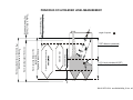
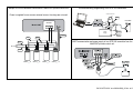
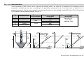
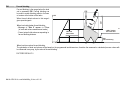
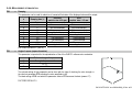
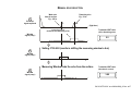
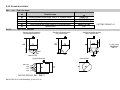
INSTALLATION
and
PROGRAMMING MANUAL
2nd edition
Manufacturer:
NIVELCO Process Control Co.
1043 Budapest, Dugonics u. 11.
Tel: (36-1) 889-0100 ♦ Fax: (36-1) 889-0200
E-mail:[email protected] ♦ www.nivelco.com
BKI 06 ATEX 021X ♦ scd3404a0600p_02.doc ♦ 1 / 36
BKI 06 ATEX 021X ♦ scd3404a0600p_02.doc ♦ 2 / 36
DIST
Far end blocking
DEFAULT value of: P06=0
Displayable range
Programmed measurement range
Max. measuring distance of the
application (H)
Programmed value of: P04=H
Max. measuring range of the device
Max. measuring distance of the device (X M)
DEFAULT value of: P04=X M
Close end blocking (XB)
Progr. value of: P05=XB>Xm
Min. meas. distance (Xm)
DEFAULT value of: P05=Xm
PRINCIPLES OF ULTRASONIC LEVEL MEASUREMENT
Angle of repose:
DIST=distance (measured)
LEV= level (calculated H-DIST)
VOL= volume (calculated from LEV)
BKI 06 ATEX 021X ♦ scd3404a0600p_02.doc ♦ 3 / 36
CONTENTS
1. INTRODUCTION .............................................................................5
2. TECHNICAL DATA .........................................................................7
2.1. GENERAL DATA ...........................................................................7
2.2. SPECIAL DATA.............................................................................7
2.3. ACCESSORIES ............................................................................8
2.4. ORDER CODES ............................................................................8
2.5. DIMENSIONS ...............................................................................9
3. INSTALLATION.............................................................................10
4. WIRING..........................................................................................12
4.1. WIRING CONDITIONS .................................................................12
4.2. CONNECTION CABLE EXTENSION ................................................12
5. PUTTING INTO OPERATION, ADJUSTING, PROGRAMMING ..14
5.1. PUTTING INTO OPERATION .........................................................14
5.1.1. Status indication signals in measuring mode ..................15
5.2. SAFETY REGULATIONS OF THE EX APPROVED UNITS ....................15
5.3. PROGRAMMING .........................................................................15
5.4. PARAMETERS – DESCRIPTION AND PROGRAMMING .....................16
5.4.1. Measurement Configuration............................................16
5.4.2. Current value...................................................................21
5.4.3. Relay output ....................................................................22
5.4.4. Measurement optimalization ...........................................23
5.4.5. Volume measurement .....................................................28
5.4.6. Linearisation....................................................................29
5.4.7. Informational parameters ................................................30
5.4.8. Test parameters ..............................................................31
5.4.9. Error codes......................................................................32
BKI 06 ATEX 021X ♦ scd3404a0600p_02.doc ♦ 4 / 36
6. MAINTENANCE, REPAIR ............................................................ 33
7. STORAGE CONDITIONS ............................................................. 33
8. PARAMETER TABLE................................................................... 34
Thank you for choosing a NIVELCO instrument.
We are sure that you will be satisfied throughout its use.
1. INTRODUCTION
APPLICATION
The EASYTREK SCD - 300 series compact ultrasonic transmitters from NIVELCO are designed to measure the level of free flowing solids, granules and powders.
The unit does not touch the material to be measured and does not include any moving parts. Thus, it is not exposed to mechanical loading, no abrasive effect is
expected and regular maintenance is not required.
A Total beam angle of 5° at –3 dB is a feature of all Nivelco’s ultrasonic sensors designed for the level measurement of free flowing solids.
This uniquely narrow beam angle ensures reliable measurement in narrow silos with uneven side walls or sometimes even in the presence of dusting.
Furthermore, as a result of the narrow beam angle – the emitted ultrasonic signals have an outstanding focusing – a sufficient signal penetration through dust is
ensured.
PRINCIPLE OF OPERATION
X
The ultrasonic level metering technology is based on the principle of measuring
the time required for the ultrasound pulses to make a round trip from the sensor to
the level to be measured and back.
The sensor emits an ultrasonic pulse train and receives the echoes reflected. The
intelligent electronic device processes the received signals by selecting the
echoes reflected from the surface and calculates the distance from the time of
flight between the sensor and the surface of the medium. This is the basis for all
other output signals (level or volume) of the EasyTREK! For measuring the level
of the medium the greatest distance of the application (H) has to be programmed.
X
D
r
D
5m
10 m
0,7 m
1,2 m
20 m
2m
30 m
3m
40 m
3,8 m
50 m
4,7 m
Diameters corresponding to the
5° beam angle
Minimum measuring distance (Xm) is the construction defined smallest distance within which measurement is not possible (Dead Band; see 5.3. Parameters P05).
In special applications this range should be extended with programming (close end blocking)
Maximum measuring distance (XM): is the construction defined greatest distance, which can be measured by the unit under ideal conditions. No measurement is
possible over this distance i.e. maximum distance of the application H must not be greater than XM. Under unfavourable circumstances such as bad reflection or heavy
dusting of the material the measuring capability may be reduced up to the half of the unit’s best performance.
BKI 06 ATEX 021X ♦ scd3404a0600p_02.doc ♦ 5 / 36
THE FOLLOWING TYPES OF APPLICATIONS ARE POSSIBLE DEPENDING ON THE COMMUNICATION AND WHAT THE OUTPUT SIGNAL IS USED FOR:
1.
Using the unit as a three - or four -wire current transmitter.
Normally, we use the analogue (4…20 mA) output signal of the EasyTREK. The application parameters of the device are set through HART communication at
installation (right after installation or in a laboratory, prior to installation). In this case the short address of the device should stay the factory default: P19 = 0.
2.
Using both, current transmission and digital (HART) signal transfer in single transmitter systems.
Digital signal transfer is also used beside the standard utilisation of the output current of the EasyTREK. In this case, there can be one or more devices in the
current loop that use analogue signals (with their total resistance being Rt = 250 … 600 Ω) and one HART master device.
The short address of the EasyTREK should stay the factory default: P19 = 0. This application can be achieved with using a PE-10 or a PR-1 type
MultiCONT unit as the HART master which ensures the power supply of the EasyTREK too.
3.
Simultaneous control of several EasyTREK transmitters with the help of a MultiCONT.
In this case all of the EasyTREK s keep the connection with the MultiCONT through HART communication only.
This means that the measurement values are collected in cycles, and that the modifications of the transmitter settings are arbitrary.
The short addresses of the units are P19 = 1 ... 15. All types of setting and programming tasks can be done through a MultiCONT.
BKI 06 ATEX 021X ♦ scd3404a0600p_02.doc ♦ 6 / 36
2. TECHNICAL DATA
2.1. GENERAL DATA
Type
Housing material
Total beam angle (-3dB)
Process temperature
Max. surface temperature
Process pressure (absolute)
Power supply / consumption
Analogue
Error indication
Output
Digital communication
Relay
Accuracy*
Resolution
Damping
Electric connection
Electric protection
Ingress protection
Ex marking
EasyTREK SCD– 3 - 4
EasyTREK SCD– 3 - 8 Ex
Aluminium
PP+Aluminium
~ 5°
–30 °C ... +60 °C
–20 °C ... +60 °C
–
130 °C
0.07 ... 0.11 MPa (0,7 … 1,1 bar) Pabsolute ±0.01MPa (0.1 bar) difference between ambient and tank pressure
11.4 … 40 V DC / 4.7 W, 11.4 … 28 V AC / 5.2 VA
4 … 20 mA, Rtmax = 600 ohm, Galvanic isolation; protection against surge transients
if no echo: continuous 3.6 mA or 22 mA (selectable with programming)
HART
SPST ; 48 V AC / 5A; A12
±( 0,2% of the measured distance + 0,1% of the range)
10 mm
3 … 1000 s (default: 300 s)
6 x 2.5 mm2 ∅ 7.5 mm shielded cable; standard length 3 m ; (to order up to 30 m)
Class III
IP65
–
ATEX
II 1 D IP65 T130°C
*Under optimal circumstances of reflection and stabilised sensor temperature
2.2. SPECIAL DATA
Type
Maximum measuring distance (XM)
Minimum measuring distance (Xm)
Ultrasound frequency
Sensor face
Mass
SCD-34 - 4
SCD-34 - 8 Ex
15 m
0.5 m
40 kHz
~ 3.5 kg
SCD-33 - 4
SCD-33 - 8 Ex
30 m
0.6 m
30 kHz
PVC foam
~ 3.5 kg
SCD-31 - 4
SCD-31 - 8 Ex
60 m
1m
15 kHz
~ 6.5 kg
BKI 06 ATEX 021X ♦ scd3404a0600p_02.doc ♦ 7 / 36
2.3. ACCESSORIES
•
•
•
•
Installation and Programming Manual
Certificate of Warranty
Declaration of Conformity
EView Light configuration software and description on CD
ACCESSORIES TO BE ORDERED
•
•
Split flange (order code: SFA – 35)
EView configuration software CD
2.4. ORDER CODES
EasyTREK
Range
60 m
30 m
15 m
Code
1
3
4
S
C
D – 3
Mounting
1" BSP + nut
1” BSP + fast connecting gland
Aiming device
200 mm bracket
500 mm bracket
700 mm bracket
* The order code of an Ex version should end in “Ex”
BKI 06 ATEX 021X ♦ scd3404a0600p_02.doc ♦ 8 / 36
–
Code
0
F
J
K
L
M
*
Output / Ex
4 … 20 mA+HART+Relay
4 … 20 mA+HART+Relay/Ex
RS 485+ Relay
RS 485+ Relay / Ex
Code
4
8
B
F
2.5. DIMENSIONS
SCD-310-_
SCD-330-_
SCD-340-_
SCD-310-_ Ex
SCD-31J-_
SCD-31J-_ Ex
SCD-330-_ Ex
SCD-340-_ Ex
SCD-33J-_
SCD-34J-_
SCD-33J-_ Ex
SCD-34J-_ Ex
Ball-joint Housing
(view from above)
BKI 06 ATEX 021X ♦ scd3404a0600p_02.doc ♦ 9 / 36
3. INSTALLATION
POSITIONING
Selecting optimal location for the transmitter various considerations should be made.
If the measured material is granule (material size > 5 mm) and the tank roof is dome shaped or conical, do not
install the transmitter in the centre of the tank/silo. In general the transmitter can be installed on the radius
r= (0,3 … 0,5) R.
Avoid that the 5° conical beam angle of the transmitter contact the tank/silo wall. In case the transmitter is
mounted close to the wall, it should be tilted (See section “Aiming”). Protect the transmitter electronics from
overheating due to direct sunshine. The same way no disturbing objects such as ladder, grid, thermometer, etc
should intrude into the beam cone. Heavy air movement can make measurement more difficult or even unable.
Device should be protected against direct sunshine no to let its temperature increase into excessive range.
GRAVITY FILLING
Select a location that is as
far away from the filling
point(s) as possible.
PNEUMATIC FILLING
Select a location where the speed of the in-flowing
material is the smallest.
r
R
Suggested location (view from above)
40 m
3,8 m
50 m
4,7 m
MOUNTING (see illustration of mounting options on the next page)
The EasyTREK consists of a sensor that is attached to the aiming arm (a pipe with a ball-joint housing incorporating a ball joint) that is attached to the housing of the
electronics. It is recommended to mount the transmitter on the roof of the tank/silo using a flange (see drawing above). The Ball-joint housing has a screw-hole
diameter of 125 mm for fixing it. For easy installation we recommend using our special flange with a split insertion, available in four sizes of DN125/150/200/300 (to be
ordered separately). Removing the split insertion, the flange is to be put around the aiming arm and the ball-joint housing is to be fixed to the split flange. It is essential
to use the washers and the bolts (4 pcs each) delivered with the split flange. The ball-joint will be pressed to the housing by a spring allowing adjustment/aiming.
The 4 pcs of M12 bolts have to be tightened only after completing the adjustments/aiming.
BKI 06 ATEX 021X ♦ scd3404a0600p_02.doc ♦ 10 / 36
When the entire tilting range of the aiming arm is required, the thickness of the roof can not exceed the values specified below.
The EasyTREK can also be mounted on existing (manhole) covers, access lids or for instance on a steel structure lowered into a larger (ex.: 0.5 x 0.5 m) opening on
the roof. This solution is to be used with roofs thicker than 350 …380 mm.
Diameter of the
Opening
D
160 mm
190 mm
230 mm
300 mm
340 mm
Maximum Thickness
of the Roof
V
110 mm
150 mm
200 mm
280 mm
300 mm
Illustration of mounting
BKI 06 ATEX 021X ♦ scd3404a0600p_02.doc ♦ 11 / 36
4. WIRING
4.1. WIRING CONDITIONS
•
The transmitter is SELV supplied. In the case of DC supply the connection is
independent of polarity.
Brown
Supply
Green
•
Only SELV circuits can be switched on to the relay output.
•
The house must be grounded to have noise protection; it should be
grounded to the equipotential bonding net.
Grey
•
3-wire DC powered devices can be created by connecting one of the power
supply wires to the white wire of the current output (GND). In this case the
current output becomes galvanically non-isolated.
The units and the cables should be arranged so that the fastening outside
the device relieves the end of the cable of any traction.
White
•
IOUT + HART
Pink
Relay output
Yellow
4.2. CONNECTION CABLE EXTENSION
•
It is advised to use a terminal box when cable extension is necessary.
The shielding should be connected to the shielding of the extension cable and
it should be grounded at the processing unit.
Grounding
Output for test
functions only
Colour codes of the outputs
BKI 06 ATEX 021X ♦ scd3404a0600p_02.doc ♦ 12 / 36
Housing
Multiple SCD-300 transmitters connected to a MultiCONT process control unit
Power is supplied from a common external source, the relays are not used.
Trial and laboratory programming of the SCD-300 transmitters
Output current test
mA
Grey
EasyTREK
DEVICES
White
MultiCONT
26 27 28
SELV
supply
Shielding
Grey
Brown
Green
White
HART communication and power supply of one SCD-300 transmitter from the
MultiCONT process control unit.
Brown
24 V AC/DC
Green
SCD-3_ _-4
SCD-3_ _-4
SCD-3_ _-4
SCD-3_ _-4
BKI 06 ATEX 021X ♦ scd3404a0600p_02.doc ♦ 13 / 36
5. PUTTING INTO OPERATION, ADJUSTING, PROGRAMMING
5.1. PUTTING INTO OPERATION
After switching on the correctly wired unit the transducer begins to click audibly. In about 20 … 50 s the ECHO LED goes on and a signal between 4 ... 20 mA
appears on the current output. When first powering the unit, it measures with the standard manufacturer’s settings (see some of the most important parameters
below).
Default parameters
All the transducers get the same factory default parameters that can also be reset later if needed. Some of the most important parameters of the
EasyTREK SCD-300 series can be found below.
Measurement mode: level (LEV),
4 mA is assigned to the XM maximum measuring distance (minimum level)
20 mA is assigned to the Xm minimum measuring distance (maximum level)
Current output holds last value in case of error
Damping: 300 s
All the other measurement values are set to fit the values suitable for standard tasks. The functions used in special cases are switched off.
AIMING THE SENSORS
When the material to be measured is being filled or emptied, because of the formation of an angle of repose, the vertically installed transmitter will experience a weak
signal. This can be eliminated in most cases by tilting the unit, so the aiming device is a very important part of these transmitters. The proper aiming can be set and
checked while the transmitter is being used, desirably when the silo / tank is almost empty. Usually it is best that the transmitter points to the middle of the bottom of
the silo/tank.
In cases when the silo is narrow, and the height / diameter value equals to or is more than 5, tilting is
usually not necessary. Aiming should also be checked when the silo / tank is full, because the echo can
be adversely weak even when coming from a nearby surface. This usually happens when the angle of
repose is big. In this case an optimal solution must be found in which the echo coming from any
distance is acceptable. The SERVICE PARAMETERS that can be reached during programming provide
help for set-up. That means that the aiming adjustment and the programming should be done at the
same time.
BKI 06 ATEX 021X ♦ scd3404a0600p_02.doc ♦ 14 / 36
5.1.1. STATUS INDICATION SIGNALS IN MEASURING MODE
LED status signals on the unit
HART respond signals
The properly installed device with factory default settings gives the following
responses to the COM3 universal HART command:
primary value
Level
secondary value Level
tertiary value
Distance
quaternary value Temperature
(See P01 programming).
Green LED
COM
Lights up during HART programming.
Red LED
ECHO
Lights up when the device gets proper echoes.
5.2. SAFETY REGULATIONS OF THE EX APPROVED UNITS
Ex certified devices are approved for Zone 20 and Zone 21 areas.
Transmitters must not be installed in the dust path of the pneumatic filling!
Neither the device, nor any part of it should be used as a flame-proof barrier of a Zone 20 area.
The cable outside the unit should be fixed so that it is tension-free.
The terminal box should be selected in accordance with the electrical class of the area.
As a result of the mounting arrangement of the unit the ambient temperature is equal to the
process temperature. The housing of the device should be connected to the EP network.
5.3. PROGRAMMING
HART interface of the EasyTREK enables full access and programming of the complete parameter set.
Parameters can be accessed by two ways:
- with the aid of EView or Eview light configuration software run on PC
- by the Nivelco made MultiCONT multichannel controller
This instruction describes parameters and features behind them but does not deal with technical details for their selection and editing of their values. Compact Disk
attached to the transmitter contains detailed information on the Eview configuration software (to install on PC) and its description. Programming by the MultiCONT can
be taken from its Installation and Programming Manual.
Continuous measuring is going on during programming in accordance with the last programmed parameter set. This way the analogue output signal
(4-20mA) continuously represents the actual value. The digital (HART) communication depends on the communication software. The new, modified
parameter set will be valid after returning to measurement mode. The device changes back to measurement mode automatically in 1 minute after
programming through HART communication has been finished or discontinued.
BKI 06 ATEX 021X ♦ scd3404a0600p_02.doc ♦ 15 / 36
5.4. PARAMETERS – DESCRIPTION AND PROGRAMMING
5.4.1. MEASUREMENT CONFIGURATION
P00: - c b a Application/Engineering Units
ATTENTION!
Programming of this parameter will result in loading the factory default with the corresponding engineering units.
a
1
Operating (measurement) mode
Free flowing solids level measurement
0
1
Engineering units (according to “c”)
( according to „c”)
Metric
US
m
ft
cm
inch
c
0
1
Calculation system
Metric
US
b
FACTORY DEFAULT: 001
DEVICE CAN BE OPERATED WITH TWO DIFFERENT ENGINEERING UNIT SYSTEMS, BUT FOR THE SAKE OF EASY OVERVIEW ONLY THE
METRIC SYSTEM WILL BE USED!
BKI 06 ATEX 021X ♦ scd3404a0600p_02.doc ♦ 16 / 36
P01: - - b a Measurement Mode
Values transmitted by HART protocol, current output and the switching points of the relays will be interpreted into the engineering units of the
(measured or calculated) process value corresponding to the programmed measurement mode. On the other hand, the higher the “a” of the
programmed parameter value the more (measured or calculated) process values can be transmitted through HART (e.g. if P01=0 only the Distance, if
P01=4 Distance, Level and Volume; Exception: P01=2 or 4.)
a
MEASUREMENT MODE
0
1
2
3
4
Distance
Level
Level in percent
Volume
Volume in percent
TRANSMITTED
PROCESS VARIABLES
Distance
Level
Volume
Xm
LEV
PRIMARY VARIABLES TRANSMITTED
THROUGH HART
DIST
LEV
LEV%
VOL
VOL%
OTHER VARIABLES TRANSMITTED
THROUGH HART
Secondary: LEV
Tertiary: DIST
Quaternary: Temp
VOL Factory settings
LEV
Factory settings
DIST
P11
H
P11
LEV
P10
P10
LEV %
0
100 [%]
VOL
VOL %
0
100[%]
BKI 06 ATEX 021X ♦ scd3404a0600p_02.doc ♦ 17 / 36
P02: - c b a Calculation units
a
0
1
Temperature
°C
°F
This table is interpreted according to P00(c), P01(a) and P02(c) and is irrelevant in case of percentage measurement ( P01(a)= 2 or 4 )
b
0
1
c
Volume
Metric
m3
litre
Weight (set also P32
Metric
US
tone
lb (pound)
tonne
tonne
US
ft3
gallon
The value of character c has no significance at devices for solids
FACTORY DEFAULT: 000
P03: - - - a
Values displayed – Rounding (Not used at EasyTREK)
P04: - - - -
Maximum measuring distance (H and XM)
Maximum measuring distance is the greatest distance (H) between the sensor surface and the farthest surface to be measured in the application.
Factory default of this parameter is the maximum distance (XM) that can be measured by the unit. (See table below) During programming P04 should
be set for the maximum distance (H) to be measured, whereas H ≤ XM.
EasyTREK
Maximum measuring distance
(XM) [m]
SD – 34 – SD – 33 – SD – 31 – 15
30
60
FACTORY DEFAULT: distance of XM as per table above
BKI 06 ATEX 021X ♦ scd3404a0600p_02.doc ♦ 18 / 36
Keep in mind that LEVEL (as the result of the measurement) = P04 (programmed)
– DISTANCE (measured by the device)
Since the accuracy of level (and all further calculated) value depends on the
accuracy of the max measuring distance of the application which is the
distance between the sensor face and the tank / silo bottom.
To obtain the best accuracy for liquid level measurement, measure with
EasyTREK this distance in the empty tank.
P05: - - - -
Minimum measuring distance (Close-end blocking)
Basic feature of the ultrasound level meters is their not being able to measure next to the sensor surface. Within this range the measurement can not be
interpreted, thus it should be avoided that material level get into this range. By entering a value, higher than the factory default, the minimum measuring
range will be extended and fixed to that value. Manual close-end-blocking would be used for example to block out the echo originating from the bottom
rim of a stand-off pipe or from any object protruding into the ultrasonic cone near to the transmitter.
Automatic Close-end-blocking (Automatic Dead Band control)
By using the factory default value, the unit will automatically be adjusted to the smallest possible dead band (Xm). In ideal cases this can be smaller and
in disadvantageous mountings greater than the dead band.
Manual close-end-blocking P05 = XB > Xm
Entering greater value in P05 than Xm will represent the extension of the close end blocking.
EASYTREK
SD – 34 – SD – 33 – SD – 31 – Minimum measuring
distance
(Xm) [m]
0.5
0.6
1.0
FACTORY DEFAULT: automatic close end blocking (Xm as per the table)
BKI 06 ATEX 021X ♦ scd3404a0600p_02.doc ♦ 19 / 36
Far-end blocking
Far-end blocking is the range below the level
set in parameter P06. Far-end blocking can
be used to avoid disturbing effects of stirrers
or heaters at the bottom of the tanks.
When the unit detects echoes in this range it
gives special signals.
H
When level sinks below far-end blocking:
- Message of "Sub 0" appears in EView
(in level and volume measurement mode)
- Current output holds value corresponding to
far-end blocking distance
DIST
LEV
DIS
T
P06: - - - -
“SUB 0” display
below this level
LEV=level
VOL=volume
P06
Far-end blocking
0
4mA
20mA
I out
When level rises above far-end blocking:
The calculation of level and volume will be based on the programmed tank dimensions, therefore the measured or calculated process values will not
be influenced in any way, by the value of far-end blocking.
FACTORY DEFAULT: 0
BKI 06 ATEX 021X ♦ scd3404a0600p_02.doc ♦ 20 / 36
5.4.2. CURRENT VALUE
P08: - - - -
P10: - - - P11: - - - -
Fixed output current
With this step the output current can be set as a fix value, selected between 3,8 mA and 20,5 mA. Output current will be fixed until the value of P08 is
programmed back to 0 again.
FACTORY DEFAULT: 0
Value (of distance, level or volume) assigned to 4 mA current output
Value (of distance, level or volume) assigned to 20 mA current output
Values are interpreted according to P01(a). Please note that in case of programming for (LEV or VOL) % measurement the min and max value has to
be entered in the relevant engineering units of LEV (m, ft) or VOL (m3, ft3).
Assignments can be made so that the proportion between the change of the (measured or calculated) process value and the change of the current
output be either direct or inverse. E.g. lev 1m assigned to 4mA and lev 10m assigned to 20mA represents direct proportion and lev 1m assigned to
20mA and lev 10 m assigned to 4mA represents inverse proportion.
Xm
Level display
Level transmission
[m]
Level % display
20,5 mA
DIST
LEV
P11
3,8 mA
Factory settings
P10
0
P12: - - - a
Factory settings
Iout
0 4
LEV %
20 [mA]
0
100 [% ]
FACTORY DEFAULT: P10: 0, P11: XM – Xm .(See P04 and P05)
Error indication by the current output
In case of error the EasyTREK will provide one of the current outputs below for the time the failure prevails.
a
0
1
2
Error indication (according to NAMUR)
HOLD last value
3,6 mA
22 mA
FACTORY DEFAULT: 0
BKI 06 ATEX 021X ♦ scd3404a0600p_02.doc ♦ 21 / 36
5.4.3. RELAY OUTPUT
P13: - - - -
Relay functions
a
0
Relay functions
Level
DIFFERENTIAL
LEVEL CONTROL
(Hysteresis control)
If the value selected for controlling the relay
increases over P14 : relay energises
decreases below P15 : relay de- energises
P14
P15
Time
Relay
Also to set:
P14, P15
Keep at least 2 cm
difference between P14
and P15
Energised:
De-energised:
1
2
ERROR INDICATION
“no ECHO” indicated by energised relay
“no ECHO” indicated by de-energised relay
—
—
FACTORY DEFAULT: 2
P14: …
Relay parameter – Setpoint value
FACTORY DEFAULT: 0
P15: - - - -
Relay parameter – Setpoint value
Relay set points are to be programmed for two-point control. Values should be set in the quantity selected for transmitting in parameter P01.
Keep at least 20 mm difference between P14 and P15
FACTORY DEFAULT: 0
P19: - - - -
HART short address
Short address is to enter here. The 00 short address is suitable for loop with one device only, when both analogue signal and HART is able to carry
information. For other settings see instruction in the manual for the configuration software EView supplied with the unit.
FACTORY DEFAULT: P19 = 00
BKI 06 ATEX 021X ♦ scd3404a0600p_02.doc ♦ 22 / 36
5.4.4. MEASUREMENT OPTIMALIZATION
P20: - - - a
Damping
This parameter can be used for reduction of unwanted fluctuation of the displayed value and the output.
a
Damping time [s]
0
1
2
3
4
5
6
7
8
9
None
3
6
10
30
60
100
300
600
1000
Granules
DUST
particle size >2-3 mm
particle size < 1-2 mm
For test only
Not recommended
Not recommended
Not recommended
Not recommended
Not recommended
Not recommended
Applicable
Not recommended
Recommended
Applicable
Recommended
Recommended
Recommended
Recommended
Recommended
Recommended
Applicable
Applicable
FACTORY DEFAULT: 7 ( 300 s )
P23: - - - a
Angle of repose (repose formation)
This parameter is important for the optimalisation of the of the QUEST+ software echo evaluation.
a
0
1
2
Estimated angle of repose
No angle of repose α ≅ 0
α< 15°
α > 15°
The optimal setting of this parameter can be done with the help of checking the echo strength in
the read out parameter P72 indicating the echo amplitude in dB.
The ideal setting of P23 is at which the parameter value in P72 becomes the best (nearest “0”).
FACTORY DEFAULT: 0
BKI 06 ATEX 021X ♦ scd3404a0600p_02.doc ♦ 23 / 36
P24: - - - a
Target tracking speed
With this parameter the evaluation can be sped up at the expense of the accuracy.
a
0
1
Tracking speed
Standard
Fast
2
Special
Remark
For most applications
For fast changing level
For very special cases only, as this reduces the maximum measuring range to 50% of the nominal value!
The measuring window (P25 and P33) is inactive and the EasyTREK will respond practically instantly to any target.
FACTORY DEFAULT: 0
P25: - - - a
Selection of Echo within the measuring window
A so-called measuring window is formed around the echo signal. The position of this measuring window determines the flight time for calculation of the
distance of the target. (the picture below can be seen on the test oscilloscope)
Received
signal
amplitude
Echo 2.
Echo 1.
t
"t" ultrasound flight time
Some applications involve multiple (target + disturbing) echoes even within the measuring window. Basic echo selection will be done by the Quest +
software automatically. This parameter only influences the echo selection within the measuring window.
a
0
1
2
Echo in the window to be selected
With the highest amplitude
First one
Largest one
FACTORY DEFAULT: 0
P26: - - - -
Level elevation rate (filling speed) [m/h]
FACTORY DEFAULT: 500
BKI 06 ATEX 021X ♦ scd3404a0600p_02.doc ♦ 24 / 36
Remarks
For most applications (both liquids and solids)
For applications with multiple echoes within the Measuring Window
Recommended for applications with floating material in the air
P27: - - - -
Level wane rate (emptying speed) [m/h]
Use these parameters to provide additional protection against echo loss in applications involving dust during the filling process (powders, dusting
granules). Reliability of the measurement can be enhanced by the correct setting of this parameter.
These parameters must not be smaller than the fastest possible filling/emptying rate of the actual technology.
FACTORY DEFAULT: 500
P28 - - - a
Echo-loss handling
a
Echo-loss error
indication
Remark
During short periods of echo-loss, both Eview and the analogue output will hold last value. The current output
holds last value for twice as long as set in P20 before going to the "Error Indication Mode" set in P12.
HART
0
Delayed
Echo loss
Echo LED goes out
Current output
1
None
2
Advance to full
3
Immediate
4
No echo-loss
indication in case of
empty tank/silo
Holding value
Error Code 2
2 * ”P20” time
Current 22 mA
P12=2
Holding value
Holding last value
P12=0
Current 3,6 mA
P12=1
During an echo-loss the displayed value on the EView and the analogue output value will hold last value.
When echo-loss occurs during filling, the displayed value on the EView and the analogue output value shifts
towards the "full" tank/silo state with the level elevation rate (filling speed) set in P26
In case of an echo-loss, ‘no Echo’ will appear in EView and the outputs will change according to the "Error
Indication Mode" set in P12.
Echo-loss may occur in completely empty tanks with a spherical bottom due to deflection of the ultrasonic beam, or
in case of silos with an open outlet. If the echo is lost when the tank/silo is completely empty, the indication will
correspond to empty tank, in all other cases echo-loss indication will function according to the “Delayed”.
FACTORY DEFAULT: 0
BKI 06 ATEX 021X ♦ scd3404a0600p_02.doc ♦ 25 / 36
P29
Blocking out of object
One object in the tank/silo disturbing measurement can be blocked out.
Enter distance of the object from the transducer. Use the Echo Map (P70) to read out the precise distance of disturbing objects.
FACTORY DEFAULT: 0
P31:
Sound velocity at 20°C (m/sec or ft/sec depending on P00(c) )
P32:
P33:
(m)
Use this parameter if the sound velocity in the gases above the measured surface differs largely from that of in air.
Recommended for applications where the gas is more or less homogeneous. If it is not, the accuracy of the measurement can be improved using the
32-point linearisation (P48, P49).
For sound velocities in various gases see section “Sound Velocities”.
FACTORY DEFAULT:
Metric (P00: “EU”): 343.8 m/s, US (P00: “US”): 1128 ft/s
Specific gravity
If you enter value (other than “0”) of specific gravity in this parameter, the weight will be displayed in EView instead of VOL.
FACTORY DEFAULT: 0 [kg/dm3] or [lb/ft3] depending on P00(c)
Manual echo selection by moving the Measuring Window
A so-called measuring window is formed around the echo signal (See scheme on the next page.)
The distance of the target will be calculated from the flight time in accordance with the position of the
measuring window.
Use this parameter if the EasyTREK unambiguously selects a wrong echo; for example the echo
1.
2.
reflected from the surface is much weaker than the interfering one(s) (see figure beside and on next
page).
Enter the distance of the correct echo and the software will move the measuring window and
calibrate itself to the echo found there.
To determine the distance of the correct echo, either use the Echo Map (to load-in a value from the
Echo Map, see parameter P70), or measure the distance with an appropriate device, and enter this
value in P33.
If this parameter has been used (P33 is not 0), its value will be continuously updated with the valid echo position.
This means, that in case of a power loss, the EasyTREK will restart the signal processing with the measuring window at the last updated
position. To switch-off this function, set P33= 0.
FACTORY DEFAULT: 0
BKI 06 ATEX 021X ♦ scd3404a0600p_02.doc ♦ 26 / 36
MANUAL ECHO SELECTION
1.
Received
signal amplitude
Weak echo
from the surface
Eg.: 3.85 m
Disturbing echo
Eg.: 5.2 m
1.
2.
(flight time)
t
measuring window
(locked on the disturbing echo)
Transmitted DIST value
(of the disturbing echo)
Window
signal (comp.)
5.2
t
Setting: P33=4.00 (results in shifting the measuring window to 4 m)
2.
Window
signal (comp.)
t
Measuring Window finds the echo from the surface
3.
Window
signal (comp.)
Transmitted DIST value
(the value is correct)
3.85
t
BKI 06 ATEX 021X ♦ scd3404a0600p_02.doc ♦ 27 / 36
5.4.5. VOLUME MEASUREMENT
P40: - - ba
Tank / silo shape
ba
Tank/silo shape
b0
01
02
b3
04
Standing cylindrical tank shape: value of “b” as below bottom
Standing cylindrical tank/silo with conical bottom
Standing rectangular tank/silo (with chute)
Lying cylindrical tank shape: value of “b” as bellow bottom
Spherical tank
Other parameters to be
set
P40(b), P41
P41, P43, P44
P41, P42, P43, P44, P45
P40(b), P41, P42
P41
FACTORY DEFAULT: 00
P41-45: - - - - Tank / silo dimensions
Standing cylindrical tank/silo
with hemispherical bottom
Standing cylindrical tank/silo
with conical bottom
Standing rectangular tank/silo
with or without chute
For flat bottom
P43, P44 and
P45 = 0
b=0
b=1
P40 b=3 b=2
Lying cylindrical tank
P40 b=3
b=2
b=1
b=0
FACTORY DEFAULT: P41 ... P45 = 0
BKI 06 ATEX 021X ♦ scd3404a0600p_02.doc ♦ 28 / 36
Spherical tank
5.4.6. LINEARISATION
P47:
- - - a Linearisation
Linearisation is the method of assigning requested (calibrated or calculated) level, volume or flow to values measured by the transmitter.
It can be used for instance if the sound velocity is not known (LEVEL LEVEL) or in the case of tank with other shape than under 5.4. 5.
(LEVEL VOLUME).
a
0
1
P48:
Linearisation
OFF (FACTORY DEFAULT)
ON
Number of linearisation data pairs
Number of linearisation data pairs entered in the table.
L (Left column)
i
Level values measured
1
0
2
L(2)
L(i)
nn
L(nn)
nn+1
0
32
0
FACTORY DEFAULT: 0
r (Right column)
Value assigned to transmit
r(1)
r(2)
r(i)
r(nn)
0
0
•
Conditions of correct programming of the data pairs
•
The table must always start with: L(1)= 0 and r(1)= value (assigned to 0 level)
•
The table must be ended either with the 32nd data pair i.e. j=32 or if the linearisation table contains less than 32 data-pairs j<32, it must be ended
with a level value “0” e.g. L(j<32)= 0.
•
The EasyTREK will ignore data after recognising level value “0” with serial number other than “1”.
If the above conditions are not met, error codes will be sent (see chapter: Error Codes).
Notice: for further information about programming in reference to linearisation see user’s manual of the EView software and MultiCONT
process controller
BKI 06 ATEX 021X ♦ scd3404a0600p_02.doc ♦ 29 / 36
5.4.7. INFORMATIONAL PARAMETERS
P60: - - - -
Overall operating hours of the unit (h)
P61: - - - -
Time elapsed since last switch-on (h)
P62: - - - -
Operating hours of the relay (h)
P63: - - - -
Number of switching cycles of the relay (h)
P64: - - - -
Actual temperature of the transducer (°C/°F)
Broken loop of the thermometer will be indicated by Pt Error message that is initiated by a signal sent via HART. In this case the transmitter will perform
temperature correction corresponding to 20ºC.
P65: - - - -
Maximum temperature of the transducer (°C/°F)
P66: - - - -
Minimum temperature of the transducer (°C/°F)
P70: - - - -
Number of Echoes / Echo Map
Amplitude and position of the echoes can also be read out.
Notice: for graphic display of the echoes use the EView software or a MultiCONT process controller.
BKI 06 ATEX 021X ♦ scd3404a0600p_02.doc ♦ 30 / 36
P71: - - - -
Distance of the of Measuring Window
P72 - - - -
Amplitude of the selected echo [dB] <0
P73:
Position of the selected echo (time) : (ms)[ms]
P74:
Signal to Noise Ratio
Ratio
Over 70
Between 70 and 50
Under 50
P75: - - - -
Measurement conditions
Excellent
Good
Unreliable
Blocking Distance
This parameter gives information about the actual close-end blocking distance (provided automatic blocking was selected in P05)
5.4.8. TEST PARAMETERS
P96: - - - -
Checksum
P97: - - - -
Software code (Read only parameter)
P98: - - - -
Hardware code (Read only parameter)
P99: dcba
Access lock by secret code
The purpose of this feature is to provide protection against accidental programming of parameters or by a person. not entitled. The secret code can be
any value other than 0000. Setting a secret code will automatically be activated when the EasyTREK is returned to the Measurement Mode. In order to
program locked device the secret code should be entered first in P99. Thus for entering a new code or erasing the old one the knowledge of the
previous code is necessary.
BKI 06 ATEX 021X ♦ scd3404a0600p_02.doc ♦ 31 / 36
5.4.9. ERROR CODES
Error
Code
1
No Echo
or
Err2
Err3
Err4
Err5
Err6
Err7
Err12
Err13
Err14
Err15
Err16
Error description
Causes and actions to be done
Memory error
Contact local agent
Echo loss or echo too weak to evaluate
Bad reflection from the surface, reflection not directed towards the sensor,
due to dusting excessive sound absorption. Check device selection and/or
adjustment
Hardware error
Calculation overflow
Code referring to sensor error or improper
installation/mounting, level in the dead band
The measurement is at the reliability threshold
No signal received within the measuring range
specified in P04 and P05.
Linearisation table error: L(1) and L(2) are both zero
(no valid data-pairs)
Linearisation table error: there are two same L(i) data in
the table
Linearisation table error: the r(i) values are not
monotone increasing
Linearisation table error: measured Level is higher than
the last Volume or Flow data-pair
The checksum of the program in the EEPROM is wrong
BKI 06 ATEX 021X ♦ scd3404a0600p_02.doc ♦ 32 / 36
Contact local agent
Check settings
Verify sensor for correct operation and check for correct mounting
according to Users Manual
Change aiming or try to find a better location
Review programming, also look for installation mistake
See the Section ”Linearisation”
See the Section “Linearisation”
See the Section “Linearisation”
See the Section “Linearisation”
Contact local agent
6. MAINTENANCE, REPAIR
The device does not require routine maintenance. In case dust adheres to the face of the sensor despite the self-cleaning of the sensor face through resonance,
(ex.: static build-up) it can be cleaned by pressurised air.
Equipment sent back for repair should be cleaned or sterilised by the User. The User must declare that the above has been carried out.
Repairs during or beyond the guarantee period are carried out solely by the manufacturer.
7. STORAGE CONDITIONS
Ambient temperature: -30 ... +60°C
Relative humidity: max. 98 %
BKI 06 ATEX 021X ♦ scd3404a0600p_02.doc ♦ 33 / 36
8. Parameter TABLE
Par.
Page
Description
Value
Par.
Page
Description
d c b a
P00
P01
P02
P03
P04
P05
P06
P07
P08
P09
P10
P11
P12
P13
P14
P15
P16
P17
P18
P19
P20
P21
16
17
18
18
18
19
20
P23
P24
P25
P26
P27
23
24
24
24
25
21
21
21
21
22
22
22
22
23
Application/Engineering Units
Measurement Mode
Calculation units
Values displayed - Rounding
Maximum Measuring Distance
Minimum Measuring Distance
Far End Blocking
–
Fixed output current
–
Transmitted value assigned to „4 mA”
Transmitted value assigned to „20 mA”
“Error” indication by the current output
Relay functions
Relay parameter – Setpoint value
Relay parameter – Setpoint value
–
–
–
HART short address
Damping
–
Angle of repose
Target tracking speed
Selection of Echo in the measuring window
Level elevation rate
Level descent rate
BKI 06 ATEX 021X ♦ scd3404a0600p_02.doc ♦ 34 / 36
Value
d c b a
P28
P29
P30
P31
P32
P33
P34
P35
P36
P37
P38
P39
P40
P41
P42
P43
P44
P45
P46
P47
P48
P49
P50
P51
P52
P53
P54
P55
25
26
26
26
26
28
28
28
28
28
28
29
29
Echo loss indication
Blocking out of disturbing object
–
Sound velocity in different gases
Specific gravity
Manual echo selection
–
–
–
–
–
–
Selection of tank shape/ open channel
Dimensions of tank / Open Channel
Dimensions of tank / Open Channel
Dimensions of tank / Open Channel
Dimensions of tank / Open Channel
Dimensions of tank / Open Channel
Level pertaining to flow Q= 0
Linearisation
Linearisation table
–
–
–
–
–
–
–
Par.
Page
Description
Value
Par.
Page
Description
d c b a
P56
P57
P58
P59
P60
P61
P62
P63
P64
P65
P66
P67
P68
P69
P70
P71
P72
P73
P74
P75
P76
P77
30
30
30
30
30
30
30
30
31
31
31
31
33
34
34
–
–
–
–
Overall operating hours of the unit
Time elapsed after last switch-on
Operating hours of the relay
Number of switching cycles of the relay
Actual temperature of the transducer
Maximum temperature of the transducer
Minimum temperature of the transducer
–
–
–
Echo Map
Position of the measuring window
Amplitude of the selected echo
Position of the selected echo
Signal / noise ratio
Blocking distance value
Water head of the flow
TOT1 volume flow totalised
Value
d c b a
P78
P79
P80
P81
P82
P83
P84
P85
P86
P87
P88
P89
P90
P91
P92
P93
P94
P95
P96
P97
P98
P99
34
34
34
34
34
TOT2 volume flow totalised
–
–
–
–
–
–
–
–
–
–
–
–
–
–
–
–
–
Software code 1
Software code 2
Hardware code
Access lock by secret code
BKI 06 ATEX 021X ♦ scd3404a0600p_02.doc ♦ 35 / 36
scd3404a0600p_02.doc
Oct. 2006
Nivelco reserves the right to change technical data without notice!
BKI 06 ATEX 021X ♦ scd3404a0600p_02.doc ♦ 36 / 36


![[txt] - inive](http://vs1.manualzilla.com/store/data/005930101_1-cb177862fb65c34a12278b2ed669a482-150x150.png)