1
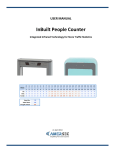
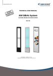
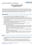
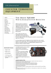
USER MANUAL
MetalSpy
EAS Add-On Technology for Foil Bag Protection
21 June 2011
User Manual – InBuilt People Counter
Contents
1.0 SPECIFICATIONS & FEATURES ........................................................................................................................................... 3
1.1 System .......................................................................................................................................................................... 3
1.2 MetalSpy Diamond ....................................................................................................................................................... 4
2.0 PCB CONNECTION............................................................................................................................................................. 4
2.1 MetalSpy Diamond ....................................................................................................................................................... 4
2.2 AM InBuilt ..................................................................................................................................................................... 5
2.3 RF InBuilt ...................................................................................................................................................................... 5
3.0 INSTALLATION PROCEDURE.............................................................................................................................................. 6
3.1 Test ............................................................................................................................................................................... 6
3.2 Set up Antenna Configuration...................................................................................................................................... 6
3.3 Power Requirements.................................................................................................................................................... 6
3.4 Antenna Placement ...................................................................................................................................................... 7
3.5 Run Cables .................................................................................................................................................................... 7
3.6 Alarm Output ............................................................................................................................................................... 8
4.0 TUNING ........................................................................................................................................................................... 10
4.1 Synchronization .......................................................................................................................................................... 10
4.2 TX................................................................................................................................................................................ 11
4.3 RX ............................................................................................................................................................................... 13
4.4 Test .............................................................................................................................................................................. 16
5.0 TROUBLESHOOTING ....................................................................................................................................................... 16
TEL: +420 271 960 054
FAX: +420 271 770 732
SUPPORT: +420 296 150 610
[email protected]
www.amersec.com
Page 2 of 17
User Manual – InBuilt People Counter
1.0 SPECIFICATIONS & FEATURES
1.1 System
Features
•- Simple manual tuning
•- Can be powered by EAS system
•- Simple to add to existing EAS installation
•- Compatible with RF and AM systems
•- Can be integrated into Amersec RF or AM systems
•- Trolley blocking
Technical Specifications
Power Input:
Power Consumption:
PSU:
12-24VDC or 15-18VAC
TX: 12W max
RX: 5W max
Allow 0.7A per Dual system
Cable Requirement:
Alarm Output:
24 AWG (0.5mm) standard twin flex cable
N/O relay switch (non-powered 2A max)
Operating Frequency
20-30kHz
System Compatibility*
•- MetalSpy Diamond
••-
AM AluProfi 40 + MS
AM AluProfi 50 + MS
••••-
RF Dual Easydet AluProfi 40 + MS
RF Dual Easydet AluProfi 40 Plexi + MS
RF Dual Easydet Crystal Smart + MS
RF Dual Easydet Crystal Clear + MS
••••-
RF Dual Superdet AluProfi 40 + MS
RF Dual Superdet AluProfi 40 Plexi + MS
RF Dual Superdet Crystal Smart + MS
RF Dual Superdet Crystal Clear + MS
*Always requires a minimum of 2 pedestals
TEL: +420 271 960 054
FAX: +420 271 770 732
SUPPORT: +420 296 150 610
[email protected]
www.amersec.com
Page 3 of 17
User Manual – InBuilt People Counter
1.2 MetalSpy Diamond
Height:
Width:
Depth:
Weight:
Base:
1680mm (66.1in)
180mm (7.1in)
37mm (1.5in)
6.2kg (13.7lb)
230 x 185 x 80mm
(9.1 x 7.3 x 3.1in)
Metal Object Size:
Detection Range:
20x30cm
30x40cm
40x50cm
up to 180cm (6ft)
up to 210cm (7ft)
up to 240cm (8ft)
2.0 PCB CONNECTION
2.1 MetalSpy Diamond
The MetalSpy TX & RX boards are connected to a simple “O” loop in the Diamond antennas. This also applies if a hidden
loop is made inside a wall. A simple loop of wire can be placed on or in the wall.
Figure 1 - Standalone MetalSpy PCB Connection
TEL: +420 271 960 054
FAX: +420 271 770 732
SUPPORT: +420 296 150 610
[email protected]
www.amersec.com
Page 4 of 17
User Manual – InBuilt People Counter
2.2 AM InBuilt
Figure 2 - AM with MetalSpy PCB Connection
2.3 RF InBuilt
RF antennas are Universal (UNI), meaning that they can be used with any Amersec RF board, and with or without
MetalSpy. To connect MetalSpy, do the following:
•
•
•
•
Connect the 3-wire cable labeled “Dual” to the small 3-crossbar module. The other end is connected to the
green 3-pin terminal on the PCB labeled RF OUTPUT (on TX board) or ANTENNA (on RX board).
Set the alarm light voltage jumper to 24V, located on the small module for the alarm light
Cut the wire labeled “Loop” and connect the 2 wires to the green terminal on the MetalSpy PCB labeled ANT.
This should be done for both TX and RX.
If MetalSpy is removed, the O-loop which is labeled “Loop” must be connected back together!
Figure 3 - RF with MetalSpy PCB Connection
TEL: +420 271 960 054
FAX: +420 271 770 732
SUPPORT: +420 296 150 610
[email protected]
www.amersec.com
Page 5 of 17
User Manual – InBuilt People Counter
3.0 INSTALLATION PROCEDURE
3.1 Test
ALWAYS test the system for performance on-site before drilling holes in the floor and mounting the antennas!!! Every
environment is different and the original plan may need to be modified!
3.2 Set up Antenna Configuration
MetalSpy operates as a Dual system, therefore it requires a Transmitter and a Receiver. If MetalSpy is integrated into an
EAS system, set up and configure the EAS system first, and then configure the MetalSpy.
Figure 4 - MetalSpy Configuration & Wiring
3.3 Power Requirements
Standalone:
2 antennas: 15VAC 0.7A or larger (or DC)
3-4 antennas: 15VAC 2A or 24VDC 2.1A
AM InBuilt:
Same as Standalone
RF InBuilt:
Can be powered from RF system. 24VDC 2.1A for maximum 4 antennas
TEL: +420 271 960 054
FAX: +420 271 770 732
SUPPORT: +420 296 150 610
[email protected]
www.amersec.com
Page 6 of 17
User Manual – InBuilt People Counter
3.4 Antenna Placement
MetalSpy operates by detecting MOVING metal objects! Therefore any moving metal near the system can cause alarms.
If the metal is stationary it will NOT be a problem.
Antennas should be FIRMLY mounting to the floor as moving antennas will appear to the system as moving metal
objects!
MetalSpy systems should not be placed behind swinging doors unless the doors have no metal pieces or remain open
throughout the store’s opening hours. The antennas should be placed minimum 50cm from the swinging doors. It must
be tested because it depends on the amount of metal on the door! More metal means a greater chance of alarms and
the antennas must be farther away.
Figure 5 - Antenna Placement with Swinging Doors
Other sources of moving metal are:
Sliding Doors: minimum 30cm away
Elevators: minimum 30cm away
Escalators: minimum 100cm away
3.5 Run Cables
No special cable types are required. Most common is standard twin flex cable. Up to 3 cables are required. A single FTP
cable may be used for all.
Power: Required to each antenna. No extra cable is required if MetalSpy is powered from RF electronics.
Alarms: Only required if you wish to connect all RX to the same alarm (example - a wireless pager). You may also wish
to run an alarm cable to another location (wall, cash desk, etc.), so it is important to consider your alarm output.
Synchronization: Only required if you have more than 1 TX
TEL: +420 271 960 054
FAX: +420 271 770 732
SUPPORT: +420 296 150 610
[email protected]
www.amersec.com
Page 7 of 17
User Manual – InBuilt People Counter
3.6 Alarm Output
Because every store wants a different type of alarm for MetalSpy (discreet alarms are recommended), no alarm is
supplied with MetalSpy. Receivers have 1 alarm output which is normally-open contact relay. There are many options
for connecting alarms. Some examples are below.
•
Wireless Pager/Alarm System (recommended). Please see the Wireless Pager manual for more details.
Figure 6 - Wireless Pager/Alarm
TEL: +420 271 960 054
FAX: +420 271 770 732
SUPPORT: +420 296 150 610
[email protected]
www.amersec.com
Page 8 of 17
User Manual – InBuilt People Counter
•
External Alarm Light (cannot be combined with the wireless pager/alarm)
Figure 7 - External Alarm Light
•
Extra Buzzer. It is recommended to find a buzzer which can be powered from the same power supply (15VAC or
24VDC) as the MetalSpy. This means you do not need to have an extra power supply just for the buzzer. Cannot
be combined with the wireless pager/alarm.
Figure 8 - Extra Buzzer Alarm
TEL: +420 271 960 054
FAX: +420 271 770 732
SUPPORT: +420 296 150 610
[email protected]
www.amersec.com
Page 9 of 17
User Manual – InBuilt People Counter
4.0 TUNING
4.1 Synchronization
All MetalSpy Transmitters must be synchronized for proper function. There are 2 methods of synchronization, and also
the possibility of using a passive TX antenna.
•
Cable Synchronization: Required for all TX installed together in 1 entrance, or within 5m of each other. A
standard twin flex cable can be used.
Figure 9 - MetalSpy TX Cable Synchronization
•
Air Synchronization: Can be used for TX that are more than 5m apart, and not using the same Receiver. It is
only required to set a different TX FREQ for each system.
Figure 10 - MetalSpy TX Air Synchronization
•
Passive TX: It is possible to connect 2 antenna loops to one TX PCB. This means that the 2nd TX antenna is just
an empty or “passive” antenna. In this case no synchronization is required between the two TX antennas,
because the signal is the same and generated from the same source. It is still important to check the TX polarity,
as described in the next section.
Figure 11 - Passive TX Connection
TEL: +420 271 960 054
FAX: +420 271 770 732
SUPPORT: +420 296 150 610
[email protected]
www.amersec.com
Page 10 of 17
User Manual – InBuilt People Counter
4.2 TX
Figure 12 - MetalSpy TX
AC 15V: Input voltage 15-18VAC or 24VDC
ANT1: Antenna loop connection
ANT2: Antenna connection for passive (empty) antenna. It is in parallel to ANT1.
PWR: TX Power
M/S: Master/Slave jumper for cable synchronization. If in M position, a synchronization signal is sent to
another transmitter from the SNC.OUT terminal. If set to S position, the oscillator is disconnected and
the transmitter will expect a signal at SNC.IN.
6. TX FREQ: 4 possible frequencies of transmitted signals for synchronizing multiple transmitters by air.
The frequencies range from 22kHz to 28kHz.
7. SNC.OUT: Cable synchronization output to another transmitter. Recommended cable = standard
twisted pair. The shorter the better, so that less interference is induced into the cable.
8. SNC.IN: Cable synchronization input from another transmitter.
1.
2.
3.
4.
5.
***Tune the Transmitters before attempting to tune the Receivers.
•
TX Power: Not critical, but should be set approximately to the following based on the distance between TX-RX.
<140cm = 50%
140cm – 180cm = 75%
>180cm = 100%
•
TX Antenna Polarity: Required only if more than 1 TX antenna is used and you are not able to properly tune the
Receiver (see section 4.3). Two Transmitters should result in greater (combined) power. If the polarity is
incorrect, they will “cancel” each other out and the Receiver will get very little signal. Just switch the wires in
the ANT1 terminal on the TX board.
TEL: +420 271 960 054
FAX: +420 271 770 732
SUPPORT: +420 296 150 610
[email protected]
www.amersec.com
Page 11 of 17
User Manual – InBuilt People Counter
Figure 13 - TX Antenna Polarity
•
TX Antenna Consumption: (Optional) For less power consumption and optimum performance, it is possible to
tune the TX antenna loops. If using just wire loops (for example inside a wall for a hidden system), it is required
to do this step. Each TX is tuned separately.
o Measure the current consumed by the TX. Optimum consumption is 200-250mA
Figure 14 - Measure TX Consumption
o
If current is higher than 250mA, add a 1µF capacitor across the ANT1 terminal
Figure 15 - Capacitor on ANT1 Terminal
o
Repeat until the current is around 200-250mA
TEL: +420 271 960 054
FAX: +420 271 770 732
SUPPORT: +420 296 150 610
[email protected]
www.amersec.com
Page 12 of 17
User Manual – InBuilt People Counter
4.3 RX
Figure 16 - MetalSpy RX
1.
2.
3.
4.
5.
6.
7.
8.
9.
10.
11.
12.
13.
14.
15.
ALARM OUT: Normally-open output relay for alarm connection
AC 15V: Input voltage 15-18VAC or 24VDC. Consumption is approx. 100mA.
ANT SIZE: Antenna width (small = <8cm, medium = 8-15cm, large = >15cm)
MODE:
a. Jumper 1: OFF = tuning of GAIN, ON = normal operation
b. Jumper 2: OFF = tuning of BIAS, ON = normal operation
c. Jumper 3: OFF = The system will attempt to block alarms caused by large metal objects such as
shopping trolleys, but the response is slightly slower. This enables the CADDY feature.
ON = The system will not block large signals. CADDY will not be used or evaluated.
d. Jumper 4: OFF = turns of alarm for testing, ON = normal operation
*For normal operation it is always necessary to set JP1=ON, JP2=ON, JP3=ON or OFF, and
JP4=ON.
DELAY: Time delay, for which the signal must be present. Without blocking function = 0.1-1 second.
With blocking function = 0.5-3 seconds
BIAS: Sets the offset voltage of the filter circuit
CADDY: Sets the sensitivity of the detection of large signals such as shopping trolleys
SENS: Sets the receiver sensitivity
GAIN: Sets the amplitude of the input signal of the receiver
RX ANT: Antenna connection (pins 1 & 3)
LED 1-8: Signal indication LEDs
ALM: ON when alarm is activated
ADPT: ON while the system is adapting to the environment. During this time, it should not be tested
and alarms will not be activated
BLK: System filters are fully saturated. If ON, the system will not work. This LED should be OFF or
flashing (can be flashing very quickly, looks dimly lit)
PWR: ON when board is powered
TEL: +420 271 960 054
FAX: +420 271 770 732
SUPPORT: +420 296 150 610
[email protected]
www.amersec.com
Page 13 of 17
User Manual – InBuilt People Counter
***Make sure ALL Transmitters are powered ON and you have set TX PWR before tuning the RX boards. Any required
TX synchronization should also be complete.
•
GAIN: Remove Mode Jumper 1. Turn Gain until LEDs 4-5 are lit. LEDs 3-6 are acceptable
*NOTE: If you are not able to set Gain, try removing Jumper 2 and setting BIAS first.
•
BIAS: Remove Mode Jumper 2. Turn the small Bias trimmer until LEDs 4-5 are lit.
*NOTE: You may need to turn BIAS quite far until the LEDs start going up/down.
•
Replace Jumpers 1 & 2
*NOTE: If TX Power, distance between antennas, environment, or synchronization changes, the GAIN and BIAS
will need to be reset!
•
Set Mode Jumper 3 ON or OFF, depending if shopping trolleys or sliding doors should be blocked. Tuning is
easier and performance is better if this feature is not used. If used, blocking of shopping trolleys or sliding doors
may not be 100%. It depends on many factors, such as distance between antennas, size of the metal inside the
door or trolley, environment, and even the speed at which the person/door moves. In some environments, it
may not be possible to block the sliding door or shopping trolley.
•
If Jumper 3 = ON (no blocking of large signals):
o
o
o
o
o
o
o
o
Set SENS by the size of bags to be detected: a higher SENS ensures detection of smaller bags, but
susceptibility to false alarms is higher. A lower SENS can increase resistance, but only large bags will be
detected.
Remove JP4. The ALM LED will light when the detected signal is greater than the SENS threshold.
Use a bag or piece of metal with the size you would like to detect. Walk COMPLETELY through the
system to test the bag and looking at the ALM LED.
Set the SENS as low as possible, but so that it has reliable detection of your test bag.
Now set DELAY which can help reduce false alarms from short pulses and bumps to the antennas.
If the detected signal exceeds the SENS threshold, the system begins to count down the time set by
DELAY (0.1-1sec). If at the end of the delay, the signal is still present, the system will alarm. If the signal
is no longer present, the system will not alarm.
Normal DELAY setting is about 20-40%. The proper DELAY setting can help reduce false alarms but
results in a short delay in alarming. A minimum DELAY will cause the system to have a very fast reaction
speed, but it can be susceptible to false alarms.
Put JP4 back ON. The tuning is complete.
Figure 17 - MetalSpy Signal Evaluation without Blocking
TEL: +420 271 960 054
FAX: +420 271 770 732
SUPPORT: +420 296 150 610
[email protected]
www.amersec.com
Page 14 of 17
User Manual – InBuilt People Counter
•
If Jumper 3 = OFF (blocking of large signals)
o
o
o
o
o
o
o
o
o
o
Set SENS by the size of bags to be detected: a higher SENS ensures detection of smaller bags, but
susceptibility to false alarms is higher. A lower SENS can increase resistance, but only large bags will be
detected.
Remove JP4. The ALM LED will light when the detected signal is greater than the SENS threshold.
Use a bag or piece of metal with the size you would like to detect. Walk COMPLETELY through the
system to test the bag and looking at the ALM LED.
Set the SENS as low as possible, but so that it has reliable detection of your test bag.
Now set the DELAY. When Jumper 3 is OFF, the delay will now be in the range of 0.5-3sec. After a signal
is detected which exceeds the SENS threshold, the DELAY timer will start. After the timing the remaining
signal will be compared with the signal level set by CADDY. If the signal is less than CADDY, this means a
smaller, shorter signal was detected and the system will alarm. If the signal is greater than CADDY, this
means that a larger, longer signal was detected (like a trolley), so the alarm will be blocked.
By removing JP4, it can help you set the DELAY. This will enable you to easily see when the ALM light is
turning on. A large object should have a large enough delay so that it is out of the antennas before the
DELAY is finished, so the ALM light will not turn on.
Next set the CADDY. First just set to approximately the same position as SENS, and then tune depending
on the size of object that must be blocked.
SENS, DELAY, and CADDY will need to be tuned according to distance between antennas, size of bag to
be detected, and size of object to be blocked. It will require trial-and-error testing using test bags and
trolleys.
Another option for filtering trolleys is to leave SENS unchanged. Then set DELAY to be completed when
a person is just beginning to leave the field of the antennas (approximately 30cm past the antennas). So
the system will detect the metal bag. When a trolley passes through, the signal will be much larger, so
just set CADDY to a lower value which is enough to block the trolley signal. The result is trolley filtering
with a relatively short delay. However, it will not be quite as good as the first option.
To use this option, set SENS to 80%, a short delay (30-40%), and the lowest CADDY sensitivity (0% - far
left). So the bag should always be detected. Then increase CADDY to filter the trolley, depending on its
size.
Put JP4 back ON. The tuning is complete.
Figure 18 - MetalSpy Signal Evaluation with Blocking
TEL: +420 271 960 054
FAX: +420 271 770 732
SUPPORT: +420 296 150 610
[email protected]
www.amersec.com
Page 15 of 17
User Manual – InBuilt People Counter
4.4 Test
The system can be tested after it has finished adapting (ADPT LED is off).
Figure 19 - Booster Bag
Thieves using foil-lined booster bags will usually use 2 bags. The foil will be between them. To make a booster bag for
testing, it is recommended to use a minimum of 5 layers of foil. Thieves will often use an entire roll to make sure the
EAS tags are 100% shielded.
The surface area is important. When testing, the large side of the bag should be parallel to the antennas for best
detection. If the bag passes through with the small side facing the antennas, it may not be detected.
5.0 TROUBLESHOOTING
The system has low detection
• Increase SENS
• Make sure you are using an appropriate sized bag with enough foil
• If using more than 1 TX, check polarity (see section 4.2)
• Move antennas closer together
• Change positions of RX and TX
The system is false-alarming
• Decrease SENS and/or increase DELAY
• Check TX synchronization (see section 4.1)
• Check for moving metal doors, elevators, or escalators. Try to block them per section 4.3. If it is not possible,
move the antennas farther from the metal doors
• Make sure the pedestals are firmly mounted to the floor. They cannot be moving, even slightly
• Change positions of RX and TX
TEL: +420 271 960 054
FAX: +420 271 770 732
SUPPORT: +420 296 150 610
[email protected]
www.amersec.com
Page 16 of 17
User Manual – InBuilt People Counter
The system is unstable (pulsing LEDs, low detection, false alarms, constantly alarming) especially during an alarm
• Make sure the power supply is large enough (see section 3.3)
• Check TX consumption and polarity (see section 4.2)
• Look for EM (electro-magnetic) systems nearby (not compatible)
The BLK (Blanking) LED is always on (dimly lit means it can be flashing very quickly – this is okay)
• Usually happens when installed with an AM system – try to move it farther away from the AM system
• Re-tune the system
• Change positions of RX and TX
• If using more than 1 TX, check synchronization and polarity (see sections 4.1-4.2)
The system does not work at all
• Make sure PWR LEDs are on
• Make sure TX PWR, GAIN, and BIAS have been tuned (see section 4.3)
• Check BLK LED (see above)
• Check all wire connections
• Make sure an alarm is connected (see section 3.6)
• Make sure TX is not set to Slave without a Master connection (see section 4.1)
• Remove Jumper 1. The RX LEDs should move when turning GAIN or TX PWR. If not:
o Use an oscilloscope to check for a signal coming from the TX ANT1 terminal. If none, send the TX board
to Amersec to be repaired. If there is a signal, there may be a defect on the RX board. Please send to
Amersec for repair
There is no alarm
• Make sure the alarm is powered. The MetalSpy alarm output is only a relay without power
• If using the wireless pager/alarm, the Power LED should be on, and the Alarm LED will flash during an alarm
o Make sure the antenna is connected well
o Try using a smaller antenna (just a 7cm piece of small, stiff wire). Connect it only in the left pin
The system will not block the sliding/swinging doors
• Try changing positions of TX and RX
• Move the antennas farther away
The system will not block shopping trolleys
• Make sure it has been set correctly according to section 4.3
• The signal may be too strong and it cannot be installed in this location. You may consider upgrading to the
Amersec NG Metal&MagnetSpy system, which has more advanced functions
The system is detecting other objects
• For laptops, this is normal. The size is similar to foil bags and it is not possible to differentiate
• For large shopping trolleys, wheelchairs, and baby strollers, try blocking them according to section 4.3
• For small baby strollers or other large devices with some metal and mostly plastic, it may not be possible to
block them as the amount of metal is similar to a foil bag
©American Security 2011
Manual subject to change without notice.
TEL: +420 271 960 054
FAX: +420 271 770 732
SUPPORT: +420 296 150 610
[email protected]
www.amersec.com
Page 17 of 17