1
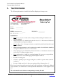
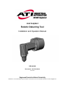
Axial Compliant Robotic Deburring Tool Installation and Operation Manual 9150-AC-90 Document #: 9610-50-1000-09 June 2012 Engineered Products for Robotic Productivity Pinnacle Park • 1031 Goodworth Drive • Apex, NC 27539 • Tel: 919.772.0115 • Fax: 919.772.8259 • www.ati-ia.com • Email: [email protected] Hiac Installation and Operation Manual Document: 9610-50-1000-09 ! CAUTION: This manual describes the function, application and safety considerations of this product. This manual must be read and understood before any attempt is made to install or operate this product, otherwise damage to this product or unsafe conditions may occur. Information contained in this document is the property of ATI Industrial Automation, Inc. (ATI) and shall not be reproduced in whole or in part without prior written approval of ATI. The information herein is subject to change without notice. This manual is periodically revised to reflect and incorporate changes made to the product. The information contained herein is confidential and reserved exclusively for the customers and authorized agents of ATI Industrial Automation and may not be divulged to any third party without prior written consent from ATI. No warranty including implied warranties is made with regard to accuracy of this document or fitness of this device for a particular application. ATI Industrial Automation shall not be liable for any errors contained in this document or for any incidental or consequential damages caused thereby. ATI Industrial Automation also reserves the right to make changes to this manual at any time without prior notice. ATI assumes no responsibility for any errors or omissions in this document. Users’ critical evaluation of this document is welcomed. Copyright by ATI Industrial Automation. All rights reserved. How to Reach Us Sales, Service and Information about ATI products: ATI Industrial Automation 1031 Goodworth Drive Apex, NC 27539 USA www.ati-ia.com Tel: 919.772.0115 Fax: 919.772.8259 E-mail: [email protected] Technical support and questions: Application Engineering Tel: 919.772.0115, Option 2, option 2 Fax: 919.772.8259 E-mail: [email protected] Pinnacle Park • 1031 Goodworth Drive • Apex, NC 27539 • Tel: 919.772.0115 • Fax: 919.772.8259 • www.ati-ia.com • Email: [email protected] 2 Hiac Installation and Operation Manual Document: 9610-50-1000-09 Table of Contents 1. Safety Precautions........................................................................................................................... 4 2. Tool Information............................................................................................................................... 5 3. General Data ................................................................................................................................... 6 3.1 Environmental Limitations ................................................................................................... 6 3.2 Extent of Warranties and Warranty Conditions................................................................... 6 4. Handling, Installation, Storage and Transportation ......................................................................... 7 4.1 Inspection of Condition when Delivered .............................................................................. 7 4.2 Unpacking and Handling ..................................................................................................... 7 4.3 Installation ........................................................................................................................... 7 4.3.1 Mounting, Adapter, and Interface Plate ................................................................ 7 4.3.2 Pneumatics ........................................................................................................... 9 4.4 4.5 Transportation and Protection during Transportation ....................................................... 10 Storage and Preventive Maintenance during storage ....................................................... 10 5. Technical Description .................................................................................................................... 11 5.1 Technical Specifications ................................................................................................... 11 6. Operating Instructions ................................................................................................................... 14 6.1 General Precautions ......................................................................................................... 14 6.2 Hiac Working Environment ............................................................................................... 15 6.3 Tool Center Point (TCP) Position ...................................................................................... 15 6.4 Operational Considerations............................................................................................... 15 6.5 Programming .................................................................................................................... 17 7. Maintenance Instructions ............................................................................................................... 18 7.1 Regular Operational Maintenance .................................................................................... 18 7.2 Lubrication......................................................................................................................... 20 7.3 Replacement of Burrs ....................................................................................................... 20 7.4 Replacement of Other Hiac Parts ..................................................................................... 21 7.5 Overhaul............................................................................................................................ 21 7.6 Repairs and Spare Parts ................................................................................................... 22 8. Drawings ........................................................................................................................................ 23 9. Terms and Conditions ................................................................................................................... 24 Pinnacle Park • 1031 Goodworth Drive • Apex, NC 27539 • Tel: 919.772.0115 • Fax: 919.772.8259 • www.ati-ia.com • Email: [email protected] 3 Hiac Installation and Operation Manual Document: 9610-50-1000-09 1. Safety Precautions Please consult Section 6.2—Hiac Working Environment in this User Manual. • Never use or start the unit without first reading and understanding this Installation and Operation Manual • Make sure that the unit is mounted into the installation position as described in Section 3.1—Environmental Limitations of this document. • Never use the unit for other purposes than those explicitly described in this document. • Never use the unit in any other way than that described. • Make sure that the pneumatic control equipment is mounted as described in Section 4.3.2—Pneumatics of this document. • Only original spare parts and files/burrs delivered from ATI must be used (see Section 7.6—Repairs and Spare Parts). • Never be near the unit while it is started or running. If it is necessary to approach the unit while in motion, stand behind appropriate Plexiglass windows. • Beware of rotating parts. • Use eye-protection (e.g., safety glasses). • The installation must be protected by a barrier to prohibit people from approaching the unit while in operation. • Beware of high sound levels.Always use hearing protection while working in the neighborhood of the unit. ATI is not liable for damages if the above instructions and instructions found elsewhere in this manual are not followed. Pinnacle Park • 1031 Goodworth Drive • Apex, NC 27539 • Tel: 919.772.0115 • Fax: 919.772.8259 • www.ati-ia.com • Email: [email protected] 4 Hiac Installation and Operation Manual Document: 9610-50-1000-09 2. Tool Information The following information is included in the Hiac shipping and storage crate: Speedeburr Pinnacle Park, 1031 Goodworth Drive, Apex, NC 27502 USA Tel: +1.919.772.0115 E-mail: [email protected] Fax: +1.919.772.8259 www.ati-ia.com Model: Serial no.: Deburring Tool ______________ ______________ Weight: _________ Min/Max. file/burr diameter: ______ Max. drive pressure: _______ Output power: _____________ Air vane motor: ____________ WARNINGS: • Never use or start the tool without first reading and understanding the Installation and Operation Manual. • Make sure that the tool is mounted as described in Section 3.1—Environmental Limitations of this Installation and Operation Manual. • Never use the tool for other purposes than those explicitly described in the Installation and Operation Manual. • Make sure that the pneumatic control equipment is mounted as described in the Installation and Operation Manual in Section 4.3.2—Pneumatics. • Only original spare parts and files/burrs delivered from the tool manufacturer must be used (see Section 7.6—Repairs and Spare Parts). • Never stand near the tool while it is started and running. If it is necessary to approach the tool while in motion, stand behind appropriate Plexiglass windows. • Be aware of rotating parts. • A barrier to prohibit people from approaching the tool while in operation must secure the installation. • Be aware of high sound levels. Always use earplugs while working near the tool. If the above instructions and instructions found in the Installation and Operation Manual are not followed, no claims may be raised against the manufacturer, or the supplier of the tool. The crate must be used whenever transporting or storing the tool. Pinnacle Park • 1031 Goodworth Drive • Apex, NC 27539 • Tel: 919.772.0115 • Fax: 919.772.8259 • www.ati-ia.com • Email: [email protected] 5 Hiac Installation and Operation Manual Document: 9610-50-1000-09 3. General Data 3.1 Environmental Limitations General: Area classification: Gas group/ignition group: Operation: Installation position: None None Mounted to robot by means of the Speedeburr adapter and flange. The flange is specific to each type of robot. This flange is normally not supplied by ATI. Mounted to a table or stand by means of the Speedeburr adapter (the robot is carrying the workpiece). Temperature range: Storage: Temperature range: Conditions: 5°C–35°C 41°F–95°F 0°C–45°C 32°F–113°F The tool should be stored in its crate and in a dry place. The tool should be kept dry and full of pneumatic oil when stored. Keep unit in crate if possible. Consult Section 4.5—Storage and Preventative Maintenance during Storage of this manual 3.2 Extent of Warranties and Warranty Conditions ATI Industrial Automation warrants the Hiac deburring tool for manufacturing errors for one (1) year from the delivery date, delivery date is defined to be the date the Hiac is shipped from ATI’s facility. The warranty is not valid if the Hiac is used for other purposes than deburring. The warranty is not valid if handling, installation, storage, transportation, operation, or maintenance of the Hiac does not comply with the instructions given in this Manual. The warranty is not valid if the warnings given are not obeyed. If the instructions in this Manual and other instructions given in writing that accompany the Hiac are not followed, no claims can be raised against the manufacturer or the supplier of the Hiac. Pinnacle Park • 1031 Goodworth Drive • Apex, NC 27539 • Tel: 919.772.0115 • Fax: 919.772.8259 • www.ati-ia.com • Email: [email protected] 6 Hiac Installation and Operation Manual Document: 9610-50-1000-09 4. Handling, Installation, Storage and Transportation 4.1 Inspection of Condition when Delivered Upon receipt, the following should be checked: - Delivery in accordance with freight documents - Damage to packaging If there is damage to any of the packaging, or if any of the goods have been exposed to abnormal handling, unpack those parts that may have been damaged for a closer inspection. If necessary, notify ATI for assistance in evaluation of the product condition. 4.2 Unpacking and Handling The Hiac tool, during transportation, storing, and handling, should always be placed inside the accompanying box (crate). 4.3 Installation 4.3.1 Mounting, Adapter, and Interface Plate Figure 4.1 is a drawing of the Speedeburr pneumatic adapter (ATI Part # 9150-H/T-3178). This adapter, or equivalent, should be used for mounting the Hiac to the robot or to other equipment. The adapter facilitates the connection of the pneumatics to the Hiac. The Hiac can be mounted on the robot or on a stand in which case the robot carries the part to be deburred to the Hiac. Refer to the drawing in Section 8—Drawings. The Hiac is mounted to the Speedeburr adapter by means of (8) M4 screws. Be sure the O-rings (Figure 7.1, Item No.10) are positioned correctly into the grooves on the Hiac bracket before mounting the Hiac to the pneumatic adapter. Removable thread locker should be used for all mounting bolts. The Speedeburr adapter is mounted to the wrist of the robot, usually by means of a robot-specific interface plate. In some cases, the Speedeburr adapter will mount directly to the robot without an interface plate. The interface plate is manufactured either by the robot supplier, the Hiac supplier, the system integrator, or by the owner/user of the Hiac. The Hiac, with the Speedeburr adapter, may be mounted to a table or stand using an interface plate or directly using the Speedeburr pneumatic adapter. Pinnacle Park • 1031 Goodworth Drive • Apex, NC 27539 • Tel: 919.772.0115 • Fax: 919.772.8259 • www.ati-ia.com • Email: [email protected] 7 Hiac Installation and Operation Manual Document: 9610-50-1000-09 (8) M4-0.7, 0.59 deep B.C. 1.732 equally spaced 0.238, 0.75 deep 0.250 0.157, 0.24 deep 1.063 CL of B.C. CL of Hiac body 0.394 (2) 0.157, 1.22 deep Interface Facing HIAC Axial force air supply #10-32 (2) Exhaust 1/4 NPT Motor Air supply 1/8 NPT Pneumatic Connections 0.2367 , 0.236 deep 0.2362 (6mm H7) B.C. 1.575 (2) Optional ports #10-32 1.9695 C' bore 1.9685 0.079 deep (50mm H7) (4) 0.242 thru C' bored opposite side, B.C. 1.575 equally spaced for M6 screws CL of Hiac body CL of C' bore & B.C. 0.250 Dimensions in inches. 2.6 Interface Facing Robot Figure 4.1—Speedeburr (Hiac) Adapter Pinnacle Park • 1031 Goodworth Drive • Apex, NC 27539 • Tel: 919.772.0115 • Fax: 919.772.8259 • www.ati-ia.com • Email: [email protected] 8 Hiac Installation and Operation Manual Document: 9610-50-1000-09 4.3.2 Pneumatics Connect the Hiac as shown in the drawing in Section 8—Drawings, Pneumatic Diagram. Two connection methods are shown. Option 1 uses one solenoid valve to control both motor drive air supply and axial force air supply. Option 2 uses two solenoid valves to independently control the two air supplies. ! CAUTION: Pneumatic components used for the motor drive circuit must be able to meet the air consumption requirements (see Section 5.1— Technical Specifications). Poor performance will result if the correct components are not used. Conventional pneumatic components (not supplied with the Hiac tool) are used to control the air supply to the Hiac. ATI recommends that the user install a pneumatic pressure regulator in order to achieve a stable air supply and to reduce the air supply to the maximum of 90 psi. The solenoid-operated valve(s) are actuated from the robot controller by means of a digital output signal. The external pressure regulator is used to control the air supply to the axial force compliance mechanism, thus enabling control of the axial force on the rotary burr. If the complete workpiece can be deburred with equal axial force, a conventional manual pressure regulator can be used. If the burrs to be removed are varying from place to place on the workpiece, and this variation is repeatable for all workpieces of the same type, it may be necessary to adjust the axial force by using an analog pressure regulator controlled from the robot controller. An analog output port in the robot controller will be needed. Function Thread Type Pressure 1/8 NPT 45–75 psi, maximum 90 psi Axial (contact) force inlet #10-32/M5 0–45 psi, maximum 45 psi Control functions #10-32/M5 Optional 1/4 NPT Not Applicable Motor inlet Exhaust Table 4.1—Pneumatic Connections It is recommended that 3/8” plastic tube be used for the motor air supply inlet, and 5/32” tube for the axial force air supply inlet. Note that a #10-32 connection is used for the axial force air supply inlet, and a 1/8 NPT connection for the motor air supply inlet. Use two silencers directly mounted on the two 1/4 NPT exhaust outlets. Information on the sound intensity is given in Section 5.1—Technical Specifications. If more noise suppression in desired, install silencers on the exhaust line further away from the Speedeburr Pinnacle Park • 1031 Goodworth Drive • Apex, NC 27539 • Tel: 919.772.0115 • Fax: 919.772.8259 • www.ati-ia.com • Email: [email protected] 9 Hiac Installation and Operation Manual Document: 9610-50-1000-09 adapter. An oil recovery unit may be installed on the exhaust line to avoid the mist lubrication droplets from entering the atmosphere around the robot installation. Additionally, to reduce the sound in neighboring working areas, a barrier (consult Section 6.2—Hiac Working Environment) surrounding the installation may be installed (Plexiglas or Lexan is preferred). The axial force air supply pressure regulator should have a 0–45 psi range. When testing for the proper contact force start with a very low pressure and increase slowly until the desired chamfer is achieved (typically 3 psi for aluminum and more for steel workpieces). Before start-up make sure the air lubrication system is filled with oil. See Section 7.2—Lubrication for proper lubricants and lubricating systems. ! CAUTION: Lack of lubrication will cause destruction of the motor within a relatively short time. If the lubrication is not working properly, you can hear the motor running slower than normal, and the speed may be varying. Install the lubrication equipment near the robot base (maximum 16 feet away from the Hiac) for proper operation. See Section 7.2—Lubrication for more about lubrication. 4.4 Transportation and Protection during Transportation The Hiac is packaged in a wooden crate designed to secure and protect it during transportation. Always use the crate when transporting the Hiac in order to minimize the risk of damage. When taking the Hiac out of the crate and carrying, or performing maintenance, try to always grab and hold it around the motor housing (please refer to the drawing in Section 8—Drawings). 4.5 Storage and Preventive Maintenance during storage The Hiac should be stored in the wooden crate when it is not in use. The Hiac should also be stored in a dry place. For short-term storage (limited to a few weeks), no preventive maintenance is needed, except for cleaning. For long-term storage, the Hiac should be thoroughly cleaned of any burrs or debris. It should not be disassembled. After cleaning, the Hiac should be "filled" with oil of the same type used as lubrication during operation. The oil should be poured into the Hiac through the adapter or through the Hiac bracket. Place the Hiac inside a sealed plastic bag and place the Hiac inside the crate. This is necessary in order to keep the blades in the air-vane motor from drying out and for preventing the risk of corrosion. Pinnacle Park • 1031 Goodworth Drive • Apex, NC 27539 • Tel: 919.772.0115 • Fax: 919.772.8259 • www.ati-ia.com • Email: [email protected] 10 Hiac Installation and Operation Manual Document: 9610-50-1000-09 5. Technical Description 5.1 Technical Specifications Main specifications for the Hiac: Motor: Speed: Torque: Power: Weight total: Weight, FFP with burr: Compensation (burr float): Axial force: Burr surface speed: Air consumption: Sound pressure level: Sound pressure value: Rotary burrs: Special tools: Air motor, vane type Idle 30,000 RPM, while deburring 18,000–25,000 RPM 0.295 ft-lbs. at lower speeds 250 W at 20,000 RPM 1.124 lbs. 0.11 lbs. Max. ± 4 mm axial and lateral, ±2 mm recommended 0.23–5.6 lbs., @ supply pressure of 0–45 psi 24.6–34.4 ft/sec, measured at 8mm dia. (halfway between center tip and outer rim) Approx. 14.1 CFM at 75 psi line pressure 75 dB(A) 87 dB(C) 1) 90° coned shape, straight fluting. 2) 90° coned shape, spiraled fluting. 3) C2, C5 Carbide Other rotary burr/file qualities on request. Burr changing tool. All noise emission measurements were taken at a distance of 3 feet from the Hiac and at a height of 5 feet from the floor. The Hiac was mounted on a laboratory test-bench. No barriers or noise-reduction facilities were used except for exhaust return to an oilrecovery-unit located beneath the test-bench. A drive pressure of 75 psi was applied (full Hiac drive pressure). No axial force pressure was applied. The Hiac was running at full idle speed. Because the working environment is not known, this method was considered the best method for measurements. The equivalent continuous A-weighted sound pressure level was measured as 75 dB (A). The peak C-weighted instantaneous sound pressure value was measured as 87 dB(C). Each Hiac goes through a thorough test procedure before it is shipped. Below are theoretical and measured forces relative to applied axial air pressure. Please note that theoretical calculations are not necessarily identical to actual data. Measurements may vary from one product to another, and should only be treated as nominal. Pinnacle Park • 1031 Goodworth Drive • Apex, NC 27539 • Tel: 919.772.0115 • Fax: 919.772.8259 • www.ati-ia.com • Email: [email protected] 11 Hiac Installation and Operation Manual Document: 9610-50-1000-09 Axial contact force 5.6 4.5 3.4 F 2.25 Axial force,lbs 1.1 0 0 2.9 5.8 8.7 11.6 14.5 17.4 20.3 23.2 4 psi Control pressure, 26.1 29 31.9 34.8 Figure 5.1—Axial Contact Force (measured with rotary burr pointing downwards) Due to pressure losses between the pressure regulator and the Free Flying Piston (FFP), the axial force is lower than theoretical calculations will predict. The actual force characteristics will change from installation to installation due to different types of pneumatic components used. 400 350 Rotor torque M, in Nmm Output power P, in W 300 250 200 Torque Pow er 150 100 50 0 0 5000 10000 15000 20000 25000 30000 Rotor ve locity, in rpm Figure 5.2—Theoretical Calculations, Hiac Output Torque and Power Pinnacle Park • 1031 Goodworth Drive • Apex, NC 27539 • Tel: 919.772.0115 • Fax: 919.772.8259 • www.ati-ia.com • Email: [email protected] 12 Hiac Installation and Operation Manual Document: 9610-50-1000-09 We recommend a working speed of 15,000 to 25,000 RPM for maximum possible output. A speed lower than 15,000 RPM is not recommended, as it increases the risk of stalling the motor, due to the higher torque at lower speeds. 30000 25000 20000 15000 Speed 10000 Rotary speed in RPM 5000 0 0 14.5 29 43.5 Drive pressure, in psi 58 72.5 87 Figure 5.3—Idle Speed as Function of Applied Drive Pressure Pinnacle Park • 1031 Goodworth Drive • Apex, NC 27539 • Tel: 919.772.0115 • Fax: 919.772.8259 • www.ati-ia.com • Email: [email protected] 13 Hiac Installation and Operation Manual Document: 9610-50-1000-09 6. Operating Instructions These operating instructions are intended to help system integrators program, start up, and complete a robotic deburring cell containing a Hiac deburring tool. The system integrator should be familiar with the task of deburring in general and should have extensive knowledge relating to robots and automation incorporating robots. The system integrator is responsible for providing user documentation for the complete deburring installation. This document is not intended to cover all aspects of such an installation, although it contains some information vital for the system user, such as maintenance instructions for the Hiac and instructions related to safety. 6.1 General Precautions It is important that all personnel involved in operation of the Hiac have a thorough understanding of the operating procedures. Failure to follow these or neglecting safety precautions can create hazardous situations, which may, in the worst case, injure personnel or damage the deburring installation and the Hiac. The Hiac must only be used for robotic deburring applications. The Hiac is a deburring tool only. DANGER: Never use the Hiac for purposes other than robotic deburring. Grinding, countersinking, or other metal-forming processes should not be performed by the Hiac. It may be dangerous to operate the Hiac for these purposes. If a failure occurs due to forces caused by improper use hazardous situations for both personnel and equipment could be created. The Hiac is intended to perform deburring only. The Hiac should not be used to deburr materials that are prone to fracture. A fracturing workpiece may result in pieces of material damaging surrounding working environment and personnel. Material removed correctly should be in the form of chips. Reduce the robot velocity when the workpiece and the Hiac are making initial contact. Making the contact movement between the Hiac and the workpiece too fast may in some situations result in a collision. Collisions may create hazardous situations for both personnel and equipment. When performing maintenance, always remember to tighten nuts and bolts thoroughly and use a removable thread lock adhesive. When replacing burrs, always attach the burr correctly. Please consult Section 7.3—Replacement of Burrs. DANGER: Never use the Hiac as a hand-held machine. Pinnacle Park • 1031 Goodworth Drive • Apex, NC 27539 • Tel: 919.772.0115 • Fax: 919.772.8259 • www.ati-ia.com • Email: [email protected] 14 Hiac Installation and Operation Manual Document: 9610-50-1000-09 In order to increase the life of the Hiac motor and bearings, always use proper lubrication. Please consult Section 7.2—Lubrication. 6.2 Hiac Working Environment As described in previous sections, the Hiac should only be used in conjunction with a robot in a secured work cell/chamber. The work cell must be secured by means of barriers to prohibit personnel from entering the cell. A lockable door should be included as a part of the barrier in order to facilitate access to the cell for authorized personnel only. The barrier could consist partly or fully of Plexiglas to facilitate observation of the deburring operations. During system or Hiac maintenance, make sure the Hiac and robot are stopped before entering the robot cell. When installing and testing, never be present in the cell when the Hiac is running. Be aware of rotating parts. Use eye-protection while working around the Hiac. Be aware of high sound levels. Always use hearing protection while working in the neighborhood of the deburring cell. 6.3 Tool Center Point (TCP) Position Figure 6.1 shows the TCP position and Hiac dimensions. When setting the TCP position in the robot controller, use the mid-position of the 0.31-inch axial stroke of the FFP. Also remember to take into account the depth of the Speedeburr adapter (please consult Section 4.3.1—Mounting, Adapter and Interface Plate). In case an additional interface plate is used in order to fit the adapter to the robot, this depth must be considered as well. TCP: Without Speedeburr adapter: Dx = 2.95 in., Dy = 0 in., Dz = -2.75 in. With Speedeburr adapter: Dx = 4.33 in., Dy = 0 in., Dz = -2.75 in. 6.4 Operational Considerations To obtain best results, it is important for the FFP to be running with low friction in the cylinder. Please consult Section 7.1—Regular and Operational Maintenance. The Hiac should not be operated for extensive periods of time with the cutting tip pointing up. This orientation will increase the amount of debris entering the cylinder and cause premature wear of the cylinder and piston, possibly preventing the piston from floating altogether. If the Hiac must be mounted in this orientation then a continuous or regular burst of high velocity air should be used to blow debris away from the piston and cylinder to insure low friction between the FFP and the cylinder. For instructions on how to replace the burr, please consult Section 7.3—Replacement of Burrs. Pinnacle Park • 1031 Goodworth Drive • Apex, NC 27539 • Tel: 919.772.0115 • Fax: 919.772.8259 • www.ati-ia.com • Email: [email protected] 15 Hiac Installation and Operation Manual Document: 9610-50-1000-09 ! CAUTION: The Hiac should not be operated for extensive periods of time with the cutting tip pointing up. This orientation will increase the amount of debris entering the cylinder and cause premature wear of the cylinder and piston, possibly preventing the piston from floating altogether. Under normal conditions, no cooling or lubrication of the rotary burr is necessary. The Hiac is used in most robot deburring installations with aluminum and steel workpieces without any coolants. 3.583 2.126 2.953 Max Min 3.858 3.54 3 0.630 1.260 Figure 6.1—Hiac and Tool Center Point (TCP) Dimensions Pinnacle Park • 1031 Goodworth Drive • Apex, NC 27539 • Tel: 919.772.0115 • Fax: 919.772.8259 • www.ati-ia.com • Email: [email protected] 16 Hiac Installation and Operation Manual Document: 9610-50-1000-09 6.5 Programming The Hiac must never be running while programming the robot. There are various techniques that may be used to program the robot path. In any case, the burr should be nominally at the mid-point of its stroke while deburring the part. It will move up and down with part and path variation. One programming method is to teach the path using the point of the burr as a guide, following the edge of the part, then manually or automatically adding offsets to the path points to achieve the final correct burr path. Another method is to program the actual points, making sure that at each point the burr is at its nominal mid-point when in contact with the part, and that there are no radial forces. The method used will depend on the robot’s capabilities and programmer preferences. If you are deburring sharp inner corners, it may be required to use the area of the burr closer to its tip. Note that, in this case, some of the compensation ability of the Hiac, as well as the cutting surface speed, is reduced. When running the robot program the first time, observe the path with the axial supply turned off. When increasing the path speed, it is important to notice that path deviation may increase with speed. Verify that at operational robot path speed the Hiac burr remains near the mid-point of its axial travel. ! CAUTION: The brass Cylinder (Figure 7.1, Item No. 5) that encloses the Free Flying Piston must be protected from collisions. If struck, it may be damaged and need replacement. The axial force of the burr should be adjusted as described in Section 4.3.2—Pneumatics in order to achieve a correct sized and even chamfer. To change the drive speed, adjust the main supply pressure; the greater the pressure, the greater the speed and vice versa. It is also possible to adjust the speed by using a small flat-blade screwdriver to turn the adjustment screw on the side of the 90-degree bracket (see Figures 7.1 and the drawing in Section 8—Drawings). This adjustment varies the flow rate, clockwise to decrease, counter-clockwise to increase the flow rate (and speed). In most applications, it is best to adjust the regulator to a maximum pressure (75–90 psi) with the adjustment screw in the full out position, approximately flush with the surface. DANGER: The Hiac must never run without proper lubrication. Damage to the unit will occur. Please consult Section 7.2—Lubrication. Pinnacle Park • 1031 Goodworth Drive • Apex, NC 27539 • Tel: 919.772.0115 • Fax: 919.772.8259 • www.ati-ia.com • Email: [email protected] 17 Hiac Installation and Operation Manual Document: 9610-50-1000-09 7. Maintenance Instructions 7.1 Regular Operational Maintenance To obtain best results, it is important for the piston to be running with low friction in the cylinder. This should be checked at regular intervals. Some debris will always enter the cylinder and regular cleaning is recommended. The Hiac should not be operated for extensive periods of time with the cutting tip pointing up. This orientation will increase the amount of debris entering the cylinder and cause premature wear of the cylinder and piston, possibly preventing the piston from floating altogether. If the Hiac must be operated in this orientation, then a continuous or regular burst of high velocity air should be used to blow debris away from the piston and cylinder to insure low friction between the FFP and the cylinder. Additionally, the outside of the Hiac should be kept clean to ensure proper cooling. Recommended Inspection and Cleaning Procedure (Refer to Figure 7.1.) • • • • • • • • • • • Remove the Lock Ring (Item No. 3) from the Hiac Motor Housing (Item No. 7) using the hook spanner wrench (not shown). Gently pull the Cylinder (Item No. 5) and Free Flying Piston (FFP) (Item No. 4) assembly from the Hiac Motor Housing. Thoroughly clean the Male Spline, the interior of the Motor Housing, and the Lock Ring with a mild solvent. Spin the burr by holding the Free Flying Piston and assure it spins freely. If it does not spin freely, replace the Free Flying Piston. Separate the FFP from the Cylinder and clean thoroughly. Inspect the FFP and Cylinder for scratches. Deep scratches may require replacement of the part(s). Check the Burr (Item No. 6) condition and replace as necessary. Lightly lubricate the outside diameter of the Free Flying Piston and the inside diameter of the Cylinder with the same oil used for operational air lubrication. Assemble the Free Flying Piston in the Cylinder and assure the Piston moves freely without excessive play. The fit between the Free Flying Piston and the Cylinder provides the seal for the axial down force air pressure, therefore the fit must be consistent and without excessive play. If the play is excessive, replace the Cylinder. Install the Cylinder and the Free Flying Piston assembly on the Motor Housing and replace the Lock Ring. Do not over tighten the Lock Ring. Assure the axial down force and the drive are working properly Pinnacle Park • 1031 Goodworth Drive • Apex, NC 27539 • Tel: 919.772.0115 • Fax: 919.772.8259 • www.ati-ia.com • Email: [email protected] 18 Hiac Installation and Operation Manual Document: 9610-50-1000-09 CAUTION: The Hiac should not be operated for extensive periods of time with the cutting tip pointing up. This orientation will increase the amount of debris entering the cylinder and cause premature wear of the cylinder and piston, possibly preventing the piston from floating altogether. ! The burr must be replaced at regular intervals. During initial production, the burr and the workpiece should be examined often in order to determine at what interval the burr should be replaced as described in Section 7.3—Replacement of Burrs. At regular intervals (normally once every two years or more often depending on the application), an overhaul of the Hiac should be performed in order to fully comply with the technical specifications. Parts inside the Hiac, such as the blades in the air-vane motor and bearings should be replaced as part of the overhaul. Please consult Section 7.5—Overhaul. At regular intervals, the pneumatics used to control the Hiac should also be checked, especially the air-filter and lubricator. Remember to fill the lubricator with oil. Item No. Qty. 1 2 3 4 5 6 7 8 9 10 1 1 1 1 1 1 1 1 1 1 Part No. Description 3500-1062012-11 Spine Lock Screw 3700-51-1002 Male Spline 3700-51-1012 Lock Ring 9005-51-1000 Free Flying Piston (FFP) 3700-51-1009 Cylinder Call ATI for Information Hiac Rotary File (Burr) 3700-51-1000 Hiac Motor Housing 3700-51-1001 90 Degree Bracket 3700-51-1015 Adjustment Screw 9150-HIAC-4796 O-ring Set Figure 7.1—User-Serviceable Parts Pinnacle Park • 1031 Goodworth Drive • Apex, NC 27539 • Tel: 919.772.0115 • Fax: 919.772.8259 • www.ati-ia.com • Email: [email protected] 19 Hiac Installation and Operation Manual Document: 9610-50-1000-09 7.2 Lubrication Before start-up, be sure a lubricator is installed as described in the pneumatic diagram in the drawing in Section 8—Drawings. Make sure the air lubrication system is filled with oil. Use oil similar to machine oil #10, spindle oil #60, Shell/Exxon ATF DEXRON II automatic transmission oil, or similar. Oilfog air lubrication systems are not recommended as a means for providing lubricated air for this product. Only microfog systems should be used. The system should be adjusted to 10–15 drops per minute. Only part of the oil drop actually enters the air stream. Fill the lubricator with the proper type of oil at regular intervals. ! CAUTION: When the system is first installed, use a higher than recommended oil setting (~2 times) until the unit is receiving consistently oiled air. If possible, run oil through the entire pneumatic tube between the oiler and the unit prior to operation. It is recommended that the exhaust containing lubrication be filtered through an oilrecovery system before exhausting it to the atmosphere. Long-time exposure to air containing oil could be dangerous for personnel. ! CAUTION: Lack of lubrication will cause untimely wear on the motor and failure within a relatively short period. If the lubrication is not working properly, the motor will run slower than normal, and may vary in speed. Install the lubrication equipment near the robot base (maximum 16 feet from the Hiac) for best results. 7.3 Replacement of Burrs Figure 7.2 shows the burr-changing tools, the Free Flying Piston (FFP), and burr (rotary file). The FFP and Cylinder should be inspected whenever a burr is replaced. The Piston should rotate freely (by hand) in the Cylinder with no binding. If binding is detected, the FFP and/or Cylinder should be replaced as described in Section 7.1—Regular Operational Maintenance. To change the burr, unscrew it with the burr-changing tools and replace it with a new one. Re-assemble the parts as described in Section 7.1—Regular Operational Maintenance. After the burr is changed and the unit re-assembled, check that the Free Flying Piston (FFP) is rotating with the burr. If the FFP is not rotating, static friction may be inspected for any visible scratches. If a burr with an imbalance is used, the FFP may also stop rotating. All burrs are checked for imbalance before they are shipped. Only original ATI burrs should be used. Pinnacle Park • 1031 Goodworth Drive • Apex, NC 27539 • Tel: 919.772.0115 • Fax: 919.772.8259 • www.ati-ia.com • Email: [email protected] 20 Hiac Installation and Operation Manual Document: 9610-50-1000-09 FFP holder 4195 Rotary Carbide File Free Flying Piston 9150–Hiac-4198 File holder 4196 Figure 7.2—Burr Replacement 7.4 Replacement of Other Hiac Parts In addition to burrs, Hiac parts such as the blades in the air-vane motor and bearings should be replaced at regular intervals (nominally every 2 years) as part of a general overhaul (see Section 7.5—Overhaul). Experience has shown that during installation, programming, and sometimes during operation, the Hiac and the workpiece collide, or the radial forces acting are too high. This sometimes results in damage to the cylinder and/or the FFP. In this case these parts may also need to be replaced. Refer to Sections 7.1—Regular Operational Maintenance and Figure 7.2. Only original spare parts supplied by ATI should be used. 7.5 Overhaul As described in previous sections of this User Manual, the motor unit and Free Flying piston should be inspected and overhauled at regular intervals. In addition to the above, the Hiac should be thoroughly cleaned, inspected and tested. This overhaul must be performed by ATI in order to maintain the technical specifications and tool life of the Hiac. Pinnacle Park • 1031 Goodworth Drive • Apex, NC 27539 • Tel: 919.772.0115 • Fax: 919.772.8259 • www.ati-ia.com • Email: [email protected] 21 Hiac Installation and Operation Manual Document: 9610-50-1000-09 7.6 Repairs and Spare Parts For repair and spare parts please contact ATI. User-serviceable parts are shown in Figure 7.2. All other repairs must be performed by ATI. ATI recommends stocking the following spare parts in addition to burrs: Part No. 9005-51-1000 3700-51-1009 9005-51-1003 Description Free Flying Piston (FFP) Cylinder AC-90, Upper Bearing Kit Only original spare parts and burrs from ATI should be used. Pinnacle Park • 1031 Goodworth Drive • Apex, NC 27539 • Tel: 919.772.0115 • Fax: 919.772.8259 • www.ati-ia.com • Email: [email protected] 22 Hiac Installation and Operation Manual Document: 9610-50-1000-09 8. Drawings Pinnacle Park • 1031 Goodworth Drive • Apex, NC 27539 • Tel: 919.772.0115 • Fax: 919.772.8259 • www.ati-ia.com • Email: [email protected] 23 Hiac Installation and Operation Manual Document: 9610-50-1000-09 9. Terms and Conditions The following Terms and Conditions are a supplement to and include a portion of ATI’s Standard Terms and Conditions, which are on file at ATI and available upon request. ATI warrants to Purchaser that robotic Speedeburr products purchased hereunder will be free from defects in material and workmanship under normal use for a period of one (1) year from the date of shipment. This warranty does not cover components subject to wear and tear under normal usage or those requiring periodic replacement. ATI will have no liability under this warranty unless: (a) ATI is given written notice of the claimed defect and a description thereof within thirty (30) days after Purchaser discovers the defect and in any event not later than the last day of the warranty period; and (b) the defective item is received by ATI not later ten (10) days after the last day of the warranty period. ATI’s entire liability and Purchaser’s sole remedy under this warranty is limited to repair or replacement, at ATI’s election, of the defective part or item or, at ATI’s election, refund of the price paid for the item. The foregoing warranty does not apply to any defect or failure resulting from improper installation, operation, maintenance or repair by anyone other than ATI. ATI will in no event be liable for incidental, consequential or special damages of any kind, even if ATI has been advised of the possibility of such damages. ATI’s aggregate liability will in no event exceed the amount paid by purchaser for the item which is the subject of claim or dispute. ATI will have no liability of any kind for failure of any equipment or other items not supplied by ATI. No action against ATI, regardless of form, arising out of or in any way connected with products or services supplied hereunder may be brought more than one (1) year after the cause of action accrued. No representation or agreement varying or extending the warranty and limitation of remedy provisions contained herein is authorized by ATI, and may not be relied upon as having been authorized by ATI, unless in writing and signed by an executive officer of ATI. Unless otherwise agreed in writing by ATI, all designs, drawings, data, inventions, software and other technology made or developed by ATI in the course of providing products and services hereunder, and all rights therein under any patent, copyright or other law protecting intellectual property, shall be and remain ATI’s property. The sale of products or services hereunder does not convey any express or implied license under any patent, copyright or other intellectual property right owned or controlled by ATI, whether relating to the products sold or any other matter, except for the license expressly granted below. In the course of supplying products and services hereunder, ATI may provide or disclose to Purchaser confidential and proprietary information of ATI relating to the design, operation or other aspects of ATI’s products. As between ATI and Purchaser, ownership of such information, including without limitation any computer software provided to Purchaser by ATI, shall remain in ATI and such information is licensed to Purchaser only for Purchaser’s use in operating the products supplied by ATI hereunder in Purchaser’s internal business operations. Without ATI’s prior written permission, Purchaser will not use such information for any other purpose or provide or otherwise make such information available to any third party. Purchaser agrees to take all reasonable precautions to prevent any unauthorized use or disclosure of such information. Purchaser will not be liable hereunder with respect to disclosure or use of information which: (a) is in the public domain when received from ATI; (b) is thereafter published or otherwise enters the public domain through no fault of Purchaser; (c) is in Purchaser’s possession prior to receipt from ATI; (d) is lawfully obtained by Purchaser from a third party entitled to disclose it; or (f) is required to be disclosed by judicial order or other governmental authority, provided that, with respect to such required disclosures, Purchaser gives ATI prior notice thereof and uses all legally available means to maintain the confidentiality of such information. Pinnacle Park • 1031 Goodworth Drive • Apex, NC 27539 • Tel: 919.772.0115 • Fax: 919.772.8259 • www.ati-ia.com • Email: [email protected] 24