1
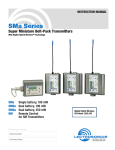
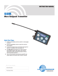
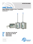
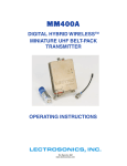
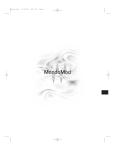
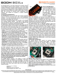
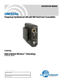
INSTRUCTION MANUAL
UM400a
Frequency Synthesized 100 mW UHF Belt-Pack Transmitter
Featuring
Digital Hybrid Wireless™ Technology
U.S. Patent 7,225,235
Fill in for your records:
Serial Number:
Purchase Date:
Rio Rancho, NM, USA
www.lectrosonics.com
UM400a
2
LECTROSONICS, INC.
Frequency Synthesized UHF Belt-Pack Transmitter
Table of Contents
General Technical Description...............................................................................................................................................................4
Introduction............................................................................................................................................................................................4
Digital Hybrid Technology......................................................................................................................................................................4
UM400a Block Diagram.........................................................................................................................................................................4
No Pre-Emphasis/De-Emphasis............................................................................................................................................................5
Pilot Tone Squelch.................................................................................................................................................................................5
Input Limiter...........................................................................................................................................................................................5
Wide-Band Deviation.............................................................................................................................................................................5
Frequency Selection..............................................................................................................................................................................5
Controls and Functions..........................................................................................................................................................................6
Input Jack...............................................................................................................................................................................................6
Power ON/OFF Switch...........................................................................................................................................................................6
Power On LED.......................................................................................................................................................................................6
Frequency Select Switches....................................................................................................................................................................6
Audio Level Control................................................................................................................................................................................7
Modulation LEDs....................................................................................................................................................................................7
Antenna..................................................................................................................................................................................................7
Adjustable Low Frequency Roll-Off........................................................................................................................................................7
Belt Clip..................................................................................................................................................................................................7
Battery Installation..................................................................................................................................................................................8
Operating Instructions............................................................................................................................................................................8
Selecting the Compatibility Mode...........................................................................................................................................................8
Attaching a Microphone and Adjusting Gain..........................................................................................................................................9
Operating Notes.....................................................................................................................................................................................9
Adjusting the Transmitter Frequency......................................................................................................................................................9
5-Pin Input Jack Wiring.........................................................................................................................................................................10
Microphone Cable Terminationfor Non-Lectrosonics Microphones.................................................................................................11
TA5F Connector Assembly..................................................................................................................................................................11
Mic Cord Stripping Instructions............................................................................................................................................................11
Crimping to Shield and Insulation........................................................................................................................................................11
Microphone RF Bypassing...................................................................................................................................................................12
Line Level Signals................................................................................................................................................................................12
Wiring Hookups for Different Sources................................................................................................................................................13
Works with Servo Inputs Only:.............................................................................................................................................................13
Compatible with Servo Inputs and other Lectrosonics Transmitters:....................................................................................................13
Replacement Parts and Accessories...................................................................................................................................................14
UHF Transmitter Antenna Specifications.............................................................................................................................................14
Troubleshooting.....................................................................................................................................................................................15
Specifications and Features.................................................................................................................................................................17
Service and Repair................................................................................................................................................................................18
Returning Units for Repair...................................................................................................................................................................18
© Copyright 2008 Lectrosonics. Inc
Rio Rancho, NM
3
UM400a
General Technical Description
Introduction
The UM400a transmitter combines 100 mW of RF
output with +/-75 kHz wide deviation for extended
operating range and extremely high signal to noise
ratio. These key design features are coupled with the
compandor-free Digital Hybrid Wireless® audio chain
and packaged in the widely recognized Lectrosonics
standard transmitter housing.
The unit is powered by a single 9V battery in the internal compartment, or from external DC using a Lectrosonics ISO9VOLT battery eliminator.
Digital Hybrid Technology
All wireless links suffer from channel noise to some degree, and all wireless microphone systems seek to minimize the impact of that noise on the desired signal. Conventional analog systems use compandors for enhanced
dynamic range, at the cost of subtle artifacts (known as
“pumping” and “breathing”). Wholly digital systems defeat
the noise by sending the audio information in digital form,
at the cost of some combination of power, bandwidth and
resistance to interference.US Patent 7,225,135
Lectrosonics Digital Hybrid Wireless™ systems overcome channel noise in a dramatically new way, digitally
encoding the audio in the transmitter and decoding it
in the receiver, yet still sending the encoded informa-
tion via an analog FM wireless link. This proprietary
algorithm is not a digital implementation of an analog
compandor but a technique that can be accomplished
only in the digital domain, even though the inputs and
outputs are analog.
Channel noise still impacts received signal quality and
will eventually overwhelm a receiver. Digital Hybrid
Wireless™ simply encodes the signal to use a noisy
channel as efficiently and robustly as possible, yielding audio performance that rivals that of wholly digital
systems, without the power and bandwidth problems
inherent in digital transmission.
Because it uses an analog FM link, Digital Hybrid Wireless™ enjoys all the benefits of conventional FM wireless systems, such as excellent range, efficient use of
RF spectrum, and resistance to interference. However,
unlike conventional FM systems, it does away with the
analog compandor and its artifacts.
No Pre-Emphasis/De-Emphasis
The Digital Hybrid Wireless™ design results in a signal-tonoise ratio high enough to preclude the need for conventional pre-emphasis (HF boost) in the transmitter and deemphasis (HF roll off) in the receiver. This eliminates the
potential for extreme distortion on signals with abundant
high-frequency information.
UM400a Block Diagram
A-D
Converter
D-A
Converter
11001001
11001001
Encoded
Audio +
Pilot Tone
+3.3v
Digital Signal Processor
9V
Battery
Switching
Power
Supply
+3.2v
+1.8v
+9v
+5v
-3v
Microprocessor
Bicolor
Power
LED
Bicolor
Modulation
LEDs
Freq
Switches
Phase Locked Loop
4MHz
Reference
4
Voltage
Controlled
Oscillator
50
Isolator
Final
Amplifier
LECTROSONICS, INC.
Frequency Synthesized UHF Belt-Pack Transmitter
Low Frequency Roll-Off
The low frequency roll-off at the 3 dB down point is variable from 35 to 150 Hz Hz to control subsonic and very
low frequency audio content in the audio. The actual
roll-off frequency will vary slightly depending upon the
low frequency response of the microphone.
Excessive low frequency content can drive the transmitter into limiting, or in the case of high level sound systems, can even cause damage to loudspeaker systems.
The roll-off is normally adjusted by ear while listening
as the system is operating.
Input Limiter
A DSP-controlled analog audio limiter is employed before
the analog-to-digital (A-D) converter. The limiter has a range
of more than 30 dB for excellent overload protection. A dual
release envelope makes the limiter acoustically transparent
while maintaining low distortion. It can be thought of as two
limiters in series, a fast attack and release limiter followed by
a slow attack and release limiter. The limiter recovers quickly
from brief transients, with no audible side effects, and also
recovers slowly from sustained high levels, to keep audio
distortion low and while preserving short term dynamics.
Signal Encoding and Pilot Tone
In addition to controlling the limiter, the DSP also encodes the digitized audio from the A-D converter and
adds an ultrasonic pilot tone to control the receiver’s
squelch. A pilot tone squelch system provides a reliable
method of keeping a receiver output muted (squelched)
even in the presence of significant interference. When
the system is operating in the hybrid mode, a different pilot tone frequency is generated for each carrier
frequency to prevent inadvertent squelch problems and
simplify multi-channel coordination.
Microprocessor, PLL and VCO Circuits
A microprocessor monitors user command inputs from
the control panel buttons and numerous other internal
signals. It works intimately with the DSP to ensure the
audio is encoded according to the selected Compatibility Mode and that the correct pilot tone is added to the
encoded signal.
Control Panel
The control panel includes four membrane switches and
an LCD screen to adjust the operational settings. Multicolor LEDs are used to indicate audio signal levels for
accurate gain adjustment and for battery status.
Wide-Band Deviation
±75 kHz deviation improves the signal to noise ratio and
audio dynamic range of a wireless system dramatically,
compared to other designs that use ±30 kHz to 40 kHz
deviation. Wide deviation combined with a high powered
transmitters makes a significant improvement in signal
to noise ratio and operating range.
Battery Options and Operating Time
Switching power supplies convert regulated battery
voltages to operate various circuit stages with maximum efficiency. With the variety of alkaline, lithium and
rechargeable batteries available today in the 9V format,
there are many choices to maximize operating time or
minimize cost as needed for any application.
Frequency Blocks
Lectrosonics established a “block” numbering system
years ago to organize the range of frequencies available from the low 500 MHz band to the upper 700
MHz band. Each block includes 256 frequencies in 100
kHz increments. The block number is part of a simple
formula to derive the frequency. The block number is
multiplied by 25.6 to produce the lowest frequency in
the block. For example, block 27 x 25.6 = 691.200.
Circulator/Isolator
The RF output circuit includes a one way circulator/isolator
using a magnetically polarized ferrite. This device greatly
reduces the RF intermodulation produced when multiple
transmitters are used in close proximity to one another
(several feet apart). The isolator also provides additional
RF output stage protection.
Compatibility Modes
Digital Hybrid transmitters were designed to operate
with Lectrosonics Digital Hybrid receivers and will yield
the best performance when doing so. However, due to
the flexibility of digital signal processing, the transmitters can also operate in various compatibility modes
for use with Lectrosonics 200 Series, Lectrosonics 100
Series, IFB and certain non-Lectrosonics receivers.
Contact the Lectrosonics sales department for a complete list of compatible non-Lectrosonics receivers.
Rio Rancho, NM
5
UM400a
Controls and Functions
Input Jack
Power LED
Power ON/OFF Switch
Low Frequency Roll Off
Control
AUDIO LEVEL Control
Modulation LEDs
ANTENNA Jack
E
D
C
B
A
F 0 1
9 8 7
2
6
3
4
5
E
D
C
B
A
F 0 1
9 8 7
2
6
3
4
5
1.6. . . . . . . . 100K
Frequency Select Switches
Input Jack
The input on the UM400a accommodates virtually every
lavaliere, hand-held or shotgun microphone available.
Different line level signals can also be accommodated.
(See Wiring Hookups for Different Sources.)
Power ON/OFF Switch
Turns the transmitter on and off. Even when the switch
is turned off or on abruptly, the pilot tone muting system
prevents “thumps” or transients from occurring.
Power On LED
The Power LED glows green when the battery is good
and the transmitter is turned on. The LED will glow
yellow/orange as the battery voltage drops and finally
glows red when there are about 30 minutes of operation
left (when using the recommended battery). The LED
blinks red when there are only a few minutes of life left.
6
NOTE: While a NiMH battery provides long
operating time, it will give little or no warning
before it is depleted. If you use a NiMH battery in
the UM400a, we recommend trying a fully charged
battery in the unit, noting the length of time that it
will run the unit, and in the future use somewhat
less than that time to determine when the battery
needs to be replaced. Digital Hybrid receivers
include timers to accurate track battery usage.
A weak battery will sometimes light the Power LED to
the “good” green indication immediately after being put
in the unit, but will quickly discharge to the point where
the LED will go red or shut down (just like a flashlight
with “dead” batteries). If the lamp fails to light, the battery should be replaced.
Frequency Select Switches
Two 16-position rotary switches adjust the center
frequency of the carrier. The left-hand switch 1.6 MHz
steps and the right-hand switch makes 100K steps.
LECTROSONICS, INC.
Frequency Synthesized UHF Belt-Pack Transmitter
Audio Level Control
Adjustable Low Frequency Roll-Off
The front panel AUDIO LEVEL Control is used to adjust
the input level (gain) for optimal modulation. The controls provides continuously variable gain over a 43 dB
range for precise adjustment.
Modulation LEDs
The Modulation LEDs provide a visual indication of the
input audio signal level from the microphone. These two
bicolor LEDs can glow either red or green to indicate
modulation levels.
Signal Level
-20 LED
-10 LED
Less than -20 dB
Off
Off
-20 dB to -10 dB Green
Off
-10 dB to +0 dB
Green Green
+0 dB to +10 dB
Red
Green
Greater than +10 dB
Red
Red
The low frequency roll-off control is used to remove
subsonic (or very low frequency) audio, often produced
by air conditioning systems, automobile traffic and other
sources. Excessive low frequency content in the audio
input can cause a variety of audio problems including
driving the transmitter into limiting. In sound reinforcement systems, as one instance, excessive low frequency content can cause excessive power amplifier drain or
even damage to loudspeaker systems.
+6
+3
0dB
Mic in 35 Hz
Roll-off
-3
Line in
-6
Mic in 150 Hz
Roll-off
-9
-12
30
The Modulation LEDs also indicate the Compatibility
Mode when the transmitter power switch is turned on.
The LEDs will blink simultaneously to indicate the mode
currently set:
• Once for 100 Series mode
• Two times for 200 Series mode
• Three times for mode 3
• Four times for Digital Hybrid Wireless (also called
the 400 Series mode)
• Five times for IFB mode (not available on very
early units)
• Six times for mode 6
100
1kHz
10k
20k
The side panel is marked to indicate the approximate
hinge point of the roll-off, but is normally adjusted while
listening to the audio. In controlled situations, such as
a motion picture production set indoors where environmental noise is minimal, the control can be rotated
counter-clockwise to permit low frequency audio to be
captured.
Belt Clip
Retaining Screw
Location
Belt Clip
Modes 3 and 6 provide compatibility with other manufacturer’s receivers - contact the factory for details.
Antenna
The flexible steel cable antenna supplied with the
transmitter is cut to 1/4 wavelength of the center of the
frequency block (the frequency range) of the transmitter. The SMA connector is a 50 Ohm RF port which can
also be connected directly to test equipment. Replacement antennas are available in pre-cut lengths for
specific frequency blocks, or as a kit with instructions to
cut the antenna for any frequency block.
Low Frequency
Roll-Off Control
Belt Clip
The belt clip may be removed for special applications by
removing one screw.
WARNING: Use ONLY the screw that is
supplied.
The circuitry is tightly fitted into this unit. A longer screw
will permanently damage the transmitter!
Rio Rancho, NM
7
UM400a
Battery Installation
Operating Instructions
To open the battery compartment, press outward on the
cover door in the direction of the arrow as shown in the
illustration. Only firm, sliding pressure is needed to open
and close the battery door. Swing the door open and take
note of the polarity marked inside showing the location of
the positive (+) and negative (-) terminals. You can also
see the large and small contact holes inside the battery
compartment with the door open.
Selecting the Compatibility Mode
Insert the battery correctly and close the cover by pressing the door closed and across, reversing the opening procedure illustrated here. If the battery is inserted
incorrectly, the door will not close. Do not force the door
closed.
The UM400a can be used with Lectrosonics 400 Series
Digital Hybrid, 200 Series analog, 100 Series analog,
Lectrosonics IFB and some non-Lectrosonics analog
wireless receivers. Contact the factory for details on the
non-Lectrosonics models that can be used. The transmitter must be set to the operating mode of the matching receiver, which is done using the supplied screwdriver and a battery.
NOTE: The unit is supplied from the factory as a
Digital Hybrid (400 series) transmitter.
1) Ensure the battery is good.
2) Turn off the transmitter.
3) With a small screwdriver (one is included with your
unit), set the Frequency Select Switches to CC. (for
Change, Change).
4) Power up the unit briefly – just long enough for the
LED’s to light up and then turn it off.
5) Change the Frequency Select Switches to one of
the following settings:
• To set Lectrosonics 100 Series mode:
set switches to 1,1
• To set Lectrosonics 200 Series mode:
set switches to 2,2
• To set Mode 3: set switches to 3,3
(contact the factory for details)
• To set Lectrosonics Hybrid mode:
set switches to 4,4
• To set IFB mode: set switches to 5,5
(not available on earlier units)
• To set Mode 6: set switches to 6,6
6) Turn the unit on, wait a couple of seconds and turn
it off again.
7) Change the Frequency Select Switches to 0,0.
8) Turn on the transmitter to complete the operation.
The LEDS will blink to indicate the selected compatibility mode. Immediately after power up, all
LEDS will blink together red, then green, followed
by the audio level LEDs (-20 and -10) blinking to
indicate the mode.
The -20 and -10 LEDs will blink:
• Once for 100 Series mode
• Two times for 200 Series mode
• Three times for Mode 3
• Four times for Hybrid mode
• Five times for IFB mode (if available)
• Six times for Mode 6
At powerup the transmitter will confirm the current
compatibility mode with the number of blinks listed
here. This setting will remain the same until you
reset it with the procedure listed above.
8
LECTROSONICS, INC.
Frequency Synthesized UHF Belt-Pack Transmitter
Attaching a Microphone and Adjusting Gain
1) Ensure the battery is in good condition.
2) Insert the microphone plug into the input jack, aligning the pins; be sure that the connector locks.
3) Attach the antenna to the SMA connector on the
top of the transmitter.
4) Mute the associated receiver’s audio output.
5) Turn on the transmitter.
6) Position the microphone in the location you will use
in actual operation. While speaking or singing at the
same voice level that will actually be used, observe
the Modulation LEDs. Adjust the AUDIO LEVEL
control until the –20 dB LED glows green with occasional red flickers and -10 dB glows green.. This
will set the gain of your transmitter for signal peaks
between +0 dB and +10 dB modulation. (See chart
below.)
Signal Level
-20 LED
-10 LED
Less than -20 dB
Off
Off
-20 dB to -10 dB Green
Off
-10 dB to +0 dB
Green Green
+0 dB to +10 dB
Red
Green
Greater than +10 dB
Red
Red
Adjusting the Transmitter Frequency
If you are experiencing interference from another signal
on your frequency, you will need to change the operating frequency of your system.
If you are using a receiver with a frequency scan function, find a clear frequency with the receiver, then set
the transmitter to match.
Note: Leave the transmitter turned off while you
search for a clear frequency.
The left switch changes the operating frequency by 1.6
MHz per step and the right switch changes it 100 kHz
per step. Start by changing the operating frequency
in 100 kHz increments to find a clear channel. If it is
not possible to find a clear channel using the 100 kHz
switch, return it to its original position and change the
1.6 MHz switch by one click then try the 100 kHz switch
again.
To gain access to these switches, slide the access door
sideways with a fingernail.
With Lectrosonics Digital Hybrid receivers, a front panel
LCD character display will indicate the correct transmitter switch settings.
(optimum)
7) Once the gain has been adjusted, the audio system
audio can be turned on to make level adjustments
in the main audio system.
NOTE: The transmitter Audio Level Control should
not be used to control the volume of your sound
system or recorder levels. This gain adjustment
matches the transmitter gain with the user’s voice
level and microphone positioning. Adjust the
receiver output level to match the sound system or
recorder.
Operating Notes
E
D
C
B
A
F 0 1
9 8 7
2
6
3
4
5
1.6 MHz
E
D
C
B
A
F 0 1
9 8 7
2
6
3
4
5
100kHz
If the audio level is too high — both LEDs will blink red
frequently or glow a steady red. This condition may
reduce the dynamic range of the audio signal.
If the audio level is too low — neither LED will glow, or
only the -20 LED will glow green. This condition may
cause hiss and noise in the audio.
Different voices will usually require different settings of
the AUDIO LEVEL control, so check this adjustment as
each new person uses the system. If several different
people will be using the transmitter and there is not time
to make the adjustment for each individual, adjust it for
the loudest voice.
Rio Rancho, NM
9
UM400a
5-Pin Input Jack Wiring
The wiring diagrams included in this section represent
the basic wiring necessary for the most common types
of microphones and other audio inputs. Some microphones may require extra jumpers or a slight variation
on the diagrams shown.
It is virtually impossible to keep completely up to date on
changes that other manufacturers make to their products,
thus you may encounter a microphone that differs from
these instructions. If this occurs please call our toll-free
number listed under Service and Repair in this manual or
visit our web site at: www.lectrosonics.com
Audio Input Jack
The Audio Input Jack for the UM400a is wired as shown
below:
PIN 1 Shield (ground) for positive biased electret lavaliere microphones. Shield (ground) for dynamic
microphones and line level inputs.
PIN 2 Bias voltage source for positive biased electret
lavaliere microphones.
PIN 3 Low impedance microphone level input for
dynamic microphones. Also accepts hand-held
electret microphones provided the microphone
has its own built-in battery.
PIN 4 Bias voltage selector for Pin 3. Pin 3 voltage (0, 2
or 4 volts) depends on Pin 4 connection.
Pin 4 tied to Pin 1: 0 V
Pin 4 Open:
2V
Pin 4 to Pin 2:
4V
PIN 5 High impedance, line level input for tape decks,
mixer outputs, musical instruments, etc.
GND
2
BIAS
3
MIC
4
BIAS SELECT
5
Servo Bias
Pin 4 to Pin 1 = 0 V
Pin 4 Open = 2 V
Pin 4 to Pin 2 = 4 V
100 Ohm
+
30uF
200 Ohm
100 Ohm
To Virtual Ground
Audio Amplifier
To Limiter Control
LINE IN
+
2.7K
10k
10
30uF
+
1
500 Ohm
1k
+5 VDC
3.3uF
SM Equivalent Input Circuit Wiring
LECTROSONICS, INC.
Frequency Synthesized UHF Belt-Pack Transmitter
Microphone Cable Termination
for Non-Lectrosonics Microphones
TA5F Connector Assembly
Mic Cord Stripping Instructions
1
4
5
2
3
VIEW FROM SOLDER
SIDE OF PINS
0.15"
0.3"
Crimping to Shield and Insulation
Strip and position the cable so that the clamp
can be crimped to contact both the mic cable
shield and the insulation. The shield contact
reduces noise with some microphones and the
insulation clamp increases ruggedness.
Insulation
Shield
Crimp these
fingers to
contact the
shield
Rio Rancho, NM
Crimp these
fingers to
clamp the
insulation
NOTE: This termination is intended for UHF
transmitters only. VHF transmitters with 5-pin
jacks require a different termination. Lectrosonics
lavaliere microphones are terminated for
compatibility with VHF and UHF transmitters,
which is different than what is shown here.
11
UM400a
Microphone RF Bypassing
Line Level Signals
When used on a wireless transmitter, the microphone
element is in the proximity of the RF coming from the
transmitter. The nature of electret microphones makes
them sensitive to RF, which can cause problems with
microphone/transmitter compatibility. If the electret
microphone is not designed properly for use with wireless transmitters, it may be necessary to install a chip
capacitor in the mic capsule or connector to block the
RF from entering the electret capsule.
The normal hookup for line level signals is: Signal Hot
to pin 5, Signal Gnd to pin 1 and pin 4 jumped to pin 1.
This allows signal levels up to 3V RMS to be applied
without limiting.
If more headroom is needed, insert a 20 k resistor in
series with pin 5. Put this resistor inside the TA5F connector to minimize noise pickup.
Some mics require RF protection to keep the radio
signal from affecting the capsule, even though the
transmitter input circuitry is already RF bypassed (see
schematic diagram).
If the mic is wired as directed, and you are having difficulty with squealing, high noise, or poor frequency
response, RF entering the capsule may be the cause.
The best RF protection is accomplished by installing RF
bypass capacitors at the mic capsule. If this is not possible, or if you are still having problems, capacitors can
be installed on the mic pins inside the TA5F connector
housing.
2 WIRE MIC
3 WIRE MIC
Preferred locations for bypass capacitors
SHIELD
SHIELD
AUDIO
AUDIO
CAPSULE
TA5F
CONNECTOR
BIAS
CAPSULE
Alternate locations for bypass capacitors
TA5F
CONNECTOR
Install the capacitors as follows. Use 330 pF capacitors. Capacitors are available from Lectrosonics. Please
specify the part number for the desired lead style.
Leaded capacitors: P/N 15117
Leadless capacitors:P/N SCC330P
NOTE: All Lectrosonics lavaliere mics are
already bypassed and do not need any additional
capacitors installed for proper operation.
12
LECTROSONICS, INC.
Frequency Synthesized UHF Belt-Pack Transmitter
Wiring Hookups for Different Sources
In addition to the microphone and line level wiring hookups illustrated below, Lectrosonics makes a number of
cables and adapters for other situations such as connecting musical instruments (guitars, bass guitars, etc.)
to the transmitter. Visit www.lectrosonics.com and
click on Accessories, or download the master catalog.
A lot of information regarding microphone wiring is also
available in the FAQ section of the web site at:
http://www.lectrosonics.com/faq.htm
Follow the instructions to search by model number or
other search options.
Compatible Wiring for Both Servo Bias Inputs and Earlier Transmitters:
2 VOLT POSITIVE BIAS 2-WIRE ELECTRET
4 VOLT POSITIVE BIAS 2-WIRE ELECTRET
PIN
SHIELD
1.5 k
AUDIO
1
2
3
3.3 k
4
5
Compatible wiring for microphones such as
Countryman E6 headworn and B6 lavaliere.
4
3
5
1
2
TA5F
PLUG
DPA MICROPHONES (Danish Pro Audio miniature models)
Most common type of wiring for lavaliere mics.
Fully compatible with 5-pin inputs on Lectrosonics
transmitters such as the LM and UM Series.
UNBALANCED LINE LEVEL SIGNALS
SLEEVE
AUDIO
This wiring is for DPA lavalier
and headset microphones.
LINE LEVEL
RCA or 1/4” PLUG
NOTE: The resistor value can range from 3k to 4k ohms.
2 VOLT NEGATIVE BIAS 2-WIRE ELECTRET
2.7 k
SHIELD
AUDIO
Compatible wiring for microphones
such as negative bias TRAM models.
NOTE: The resistor value can range from 2k to 4k ohms.
PIN
1
2
3
4
5
TIP
For signal levels up to 3V (+12 dBu) before limiting. Fully
compatible with 5-pin inputs on other Lectrosonics transmitters
such as the LM and UM Series. A 20k ohm resistor can be
inserted in series with Pin 5 for an additional 20 dB of
attenuation to handle up to 30V (+32 dBu).
PIN
1
2
3
4
5
4
3
5
1
2
TA5F
PLUG
BALANCED AND FLOATING LINE LEVEL SIGNALS
4
3
5
1
2
TA5F
PLUG
4 VOLT POSITIVE BIAS 3-WIRE ELECTRET
WITH EXTERNAL RESISTOR
XLR JACK
SHIELD
Used for 3-wire lavaliere
microphones that require an
external resistor such as the
Sanken COS-11.
SHIELD
DRAIN (BIAS)
*NOTE: If the output is balanced but center
tapped to ground, such as on all Lectrosonics
receivers, do not connect Pin 3 of the XLR jack
to Pin 4 of the TA5F connector.
TA5F
PLUG
LO-Z MICROPHONE LEVEL SIGNALS
SOURCE (AUDIO)
This wiring is fully compatible with 5-pin inputs on Lectrosonics
transmitters such as the LM and UM Series. This is the wiring
for the Lectrosonics M152 lavaliere microphone.
XLR JACK
For low impedance dynamic mics or electret
mics with internal battery or power supply.
Simple Wiring for Servo Bias Inputs Only:
2 VOLT POSITIVE BIAS 2-WIRE ELECTRET
Simplified wiring for microphones
such as Countryman B6 Lavalier
and E6 Earset models and others.
NOTE: This servo bias wiring is not compatible with earlier
versions of Lectrosonics transmitters. Check with the factory
to confirm which models can use this wiring.
4 VOLT POSITIVE BIAS 3-WIRE ELECTRET
NOTE: This servo bias wiring is not compatible with earlier
versions of Lectrosonics transmitters. Check with the factory
to confirm which models can use this wiring.
2 VOLT NEGATIVE BIAS 2-WIRE ELECTRET
Simplified wiring for microphones such as negative bias TRAM.
NOTE: This servo bias wiring is not compatible with earlier
versions of Lectrosonics transmitters. Check with the factory
to confirm which models can use this wiring.
Rio Rancho, NM
13
UM400a
Replacement Parts and Accessories
Item
Model/Part Number
Replacement wire belt clip
Lectrosonics #BCWire
Replacement whip antenna
Lectrosonics AMM (xx) - specify frequency block (xx)
UHF Transmitter Antenna Specifications
470
19
20
21
22
23
24
25
26
27
28
31
29
30
32
944
33
Whip Length
Note: Check the scale of your printout. This line should be 6.00 inches long (152.4 mm).
Lectrosonics AMM Series UHF transmitter antennas follow the color code specifications in the chart below to identify
operating frequency block range. (The frequency block range is engraved on the outside housing for each individual
transmitter.) If a situation exists whereby the antenna is defective and the antenna cap is missing, refer to the following
chart to determine the correct replacement antenna.
BLOCK
14
FREQUENCY
RANGE
CAP
COLOR
ANTENNA
WHIP LENGTH
470
470.100 - 495.600
Black
5.48”
19
486.400 - 511.900
Black
5.20”
20
512.000 - 537.500
Black
4.95”
21
537.600 - 563.100
Brown
4.74”
22
563.200 - 588.700
Red
4.48”
23
588.800 - 614.300
Orange
4.24”
24
614.400 - 639.900
Yellow
4.01”
25
640.000 - 665.500
Green
3.81”
26
665.600 - 691.100
Blue
3.62”
27
691.200 - 716.700
Violet (Pink)
3.46”
28
716.800 - 742.300
Grey
3.31”
29
742.400 - 767.900
White
3.18”
944
944.100 - 951.900
Black-w/Label
2.62”
LECTROSONICS, INC.
Frequency Synthesized UHF Belt-Pack Transmitter
Jointed Whip Antennas
The AMJ antenna is a general purpose design for any
Lectrosonics receiver or transmitter with a standard
SMA connector. The hinged joint pivots in both directions for positioning the whip at any desired angle.
AMJ KIT CUTTING TEMPLATE
Lay uncut antenna on this template and cut to length for the desired frequency block
Frequency Blocks
19
20
21
22
23
24
25
26
28
27
30
29
*Cut end of cap off
and slide over whip
33
32
31
944
470
Whip Length
*Color cap
Trim the end of the color cap and slide the remaining sleeve over the whip - OR - Glue color cap onto the end
Note: Check the scale of your printout. This line should be 6.00 inches long (152.4 mm).
BLOCKFREQUENCY
RANGE
CAP/SLEEVE
COLOR
ANTENNA
WHIP LENGTH
470
470.100 - 495.600
Black w/ Label
5.56”
141.2 mm
19
486.400 - 511.900
Black w/ Label
5.27”
133.9 mm
20
512.000 - 537.500
Black w/ Label
4.93”
125.2 mm
21
537.600 - 563.100
Brown w/ Label
4.71”
119.6 mm
22
563.200 - 588.700
Red w/ Label
4.48”
113.8 mm
23
588.800 - 614.300
Orange w/ Label
4.27”
108.5 mm
24
614.400 - 639.900
Yellow w/ Label
4.07”
103.4 mm
25
640.000 - 665.500
Green w/ Label
3.87”
98.3 mm
26
665.600 - 691.100
Blue w/ Label
3.68”
93.5 mm
27
691.200 - 716.700
Violet (Pink) w/
Label
3.52”
89.4 mm
28
716.800 - 742.300
Grey w/ Label
3.36”
85.3 mm
29
742.400 - 767.900
White w/ Label
3.22”
81.8 mm
30
768.000 - 793.500
Black-w/Label
3.08”
78.2 mm
31
793.600 - 819.100
Black-w/Label
2.97”
75.4 mm
32
819.200 - 844.700
Black-w/Label
2.89”
73.4 mm
33
844.800 - 865.000
Black-w/Label
2.81”
71.4 mm
944
944.100 - 951.900
Black-w/Label
2.53”
64.3 mm
Rio Rancho, NM
The hinged joint pivots in both
15
UM400a
Troubleshooting
Before going through the following chart, be sure that you have a good battery in the transmitter. It is important that
you follow these steps in the sequence listed.
SymptomPossible Cause
TRANSMITTER BATTERY LED OFF
1) Battery is inserted backwards.
2) Battery is dead.
NO TRANSMITTER MODULATION LEDs
1)
2)
3)
4)
Gain control turned all the way down.
Battery is in backwards. Check power LED.
Mic capsule is damaged or malfunctioning.
Mic cable damaged or mis-wired.
RECEIVER RF LAMP OFF
1)
2)
3)
4)
5)
6)
Transmitter not turned on.
Transmitter battery is dead.
Receiver antenna missing or improperly positioned.
Transmitter and receiver not on same frequency. Check
switches/display on transmitter and receiver.
Operating range is too great.
Transmitter antenna not connected
NO SOUND (OR LOW SOUND LEVEL),
1)
RECEIVER INDICATES PROPER AUDIO 2)
MODULATION
3)
4)
Receiver output level set too low.
Receiver output is disconnected; cable is defective
or mis-wired.
Transmitter is not set to same frequency as receiver. Check that
frequency select switches on receiver and transmitter match.
Sound system or recorder input is turned down.
DISTORTED SOUND
1)
2)
3)
Transmitter gain (audio level) is far too high. Check mod level
lamps on transmitter and receiver as it is being used.
(Refer to Operating Instructions - Adjusting Gain)
Receiver output may be mismatched with the sound system or
recorder input. Adjust output level on receiver to the correct
level for the recorder, mixer or sound system.
Excessive wind noise or breath “pops.. Reposition microphone
and/or use a larger windscreen.
HISS AND NOISE -- AUDIBLE DROPOUTS
Transmitter gain (audio level) far too low.
Receiver antenna missing or obstructed.
Transmitter antenna missing or folded against housing.
Operating range too great.
1)
2)
3)
4)
EXCESSIVE FEEDBACK
1)
2)
3)
16
Transmitter gain (audio level) too high. Check gain adjustment
and/or reduce receiver output level.
Transmitter too close to speaker system.
Mic is too far from user’s mouth.
LECTROSONICS, INC.
Frequency Synthesized UHF Belt-Pack Transmitter
Specifications and Features
Operating frequencies:
Frequency selection:
RF Power output:
Pilot tone:
Frequency stability:
Deviation:
Spurious radiation:
Equivalent input noise:
Input level:
Input impedance:
Dynamic mic:
Electret lavaliere:
Line level:
Input compressor:
Gain control range:
Modulation indicators:
Low frequency roll-off:
Audio frequency response (overall system):
Block 470: 470.100 - 495.600
Block 19: 486.400 - 511.900
Block 20: 512.000 - 537.500
Block 21. 537.600 - 563.100
Block 22. 563.200 - 588.700
Block 23. 588.800 - 607.90. an. 614.100 - 614.300
Block 24. 614.400 - 639.900
Block 25. 640.000 - 665.500
Block 26. 665.600 - 691.100
Block 27: 691.200 - 716.700 (export only)
Block 28. 716.800 - 742.300 (export only)
Block 29. 742.400 - 767.900 (export only)
Block 944: 944.100 - 951.900
256 frequencies in 100kHz steps
100 mW (nominal)
25 to 32 kHz frequency; 5kHz deviation
± 0.002%
± 75 kHz (max)
90 dB below carrier
–120 dBV, A-weighted
Nominal 2 mV to 300 mV, before limiting.
Greater than 1V maximum, with limiting.
300 Ohms
Input is virtual ground with servo adjusted constant current bias
2.7 k Ohms
Dual envelope compressor, >30 dB range
43 dB; semi-log rotary control
Dual bicolor LEDs indicate modulatio. of -20, -10, 0, +10 dB
referenced to full modulation.
–18 dB/octave; 35Hz to 150Hz
35 Hz to 20 kHz, +/-1 dB (The low frequency
roll-off is adjustable - see graph)
+6
+3
0dB
Mic in 35 Hz
Roll-off
-3
Line in
-6
Mic in 150 Hz
Roll-off
-9
-12
30
Controls:
Audio Input Jack:
Antenna:
Power Consumption:
Battery:
Battery Life:
Operating Temperature:
Weight:
Dimensions:
100
1kHz
10k
20k
2 position “OFF-ON” slide switch for noiseless turn on/turn off operation.
Front panel knob adjusts audio gain. Recessed control on side panel adjusts low
frequency rolloff. Rotary switches on side panel adjust transmitter frequency.
Switchcraft 5 pin locking (TA5F)
Detachable, flexible wire supplied. 50 Ohm port allows connection to test equipment.
80mA
Precision compartment auto-adjusts to accept any known alkaline 9 Volt battery.
5 hours (alkaline); 10 hours (lithium)
-20 to +140 degrees F
6.3 ozs. including battery
3.1 x 2.4 x .75 inches
Emission Designator. 180KF3E
Specifications subject to change without notice.
The FCC requires that the following statement be included in this manual:
This device complies with FCC radiation exposure limits as set forth for an uncontrolled environment.
This device should be installed and operated so that its antenna(s) are not co-located or operating in
conjunction with any other antenna or transmitter.
Rio Rancho, NM
17
UM400a
Service and Repair
If your system malfunctions, you should attempt to correct or isolate the trouble before concluding that the equipment
needs repair. Make sure you have followed the setup procedure and operating instructions. Check the interconnecting
cables and then go through the Troubleshooting section in this manual.
We strongly recommend that you do not try to repair the equipment yourself and do not have the local repair shop attempt anything other than the simplest repair. If the repair is more complicated than a broken wire or loose connection,
send the unit to the factory for repair and service. Don’t attempt to adjust any controls inside the units. Once set at the
factory, the various controls and trimmers do not drift with age or vibration and never require readjustment. There are
no adjustments inside that will make a malfunctioning unit start working.
Lectrosonics’ Service Department is equipped and staffed to quickly repair your equipment. In warranty repairs are
made at no charge in accordance with the terms of the warranty. Out-of-warranty repairs are charged at a modest flat
rate plus parts and shipping. Since it takes almost as much time and effort to determine what is wrong as it does to
make the repair, there is a charge for an exact quotation. We will be happy to quote approximate charges by phone for
out-of-warranty repairs.
Returning Units for Repair
For timely service, please follow the steps below:
A. DO NOT return equipment to the factory for repair without first contacting us by email or by phone. We need
to know the nature of the problem, the model number and the serial number of the equipment. We also need a
phone number where you can be reached 8 A.M. to 4 P.M. (U.S. Mountain Standard Time).
B. After receiving your request, we will issue you a return authorization number (R.A.). This number will help speed
your repair through our receiving and repair departments. The return authorization number must be clearly shown
on the outside of the shipping container.
C. Pack the equipment carefully and ship to us, shipping costs prepaid. If necessary, we can provide you with the
proper packing materials. UPS is usually the best way to ship the units. Heavy units should be “double-boxed” for
safe transport.
D. We also strongly recommend that you insure the equipment, since we cannot be responsible for loss of or damage to equipment that you ship. Of course, we insure the equipment when we ship it back to you.
Lectrosonics USA:
Mailing address:
Shipping address:
Lectrosonics, Inc.
Lectrosonics, Inc.
PO Box 15900
581 Laser Rd.
Rio Rancho, NM 87174
Rio Rancho, N. 87124
USAUSA
Telephone:
(505) 892-4501
(800) 821-1121 Toll-free
(505) 892-6243 Fax
Web:E-mail:
www.lectrosonics.com
[email protected]
Lectrosonics Canada:
Mailing Address:Telephone:E-mail:
49 Spadina Avenue,
(416) 596-2202
Sales:. [email protected]
Suite 303A
(877) 753-2876 Toll-free
Service. [email protected]
Toronto, Ontario M5V 2J1
(877-7LECTRO)
(416) 596-6648 Fax
18
LECTROSONICS, INC.
Frequency Synthesized UHF Belt-Pack Transmitter
Rio Rancho, NM
19
LIMITED ONE YEAR WARRANTY
The equipment is warranted for one year from date of purchase against defects in
materials or workmanship provided it was purchased from an authorized dealer. This
warranty does not cover equipment which has been abused or damaged by careless
handling or shipping. This warranty does not apply to used or demonstrator equipment.
Should any defect develop, Lectrosonics, Inc. will, at our option, repair or replace any
defective parts without charge for either parts or labor. If Lectrosonics, Inc. cannot
correct the defect in your equipment, it will be replaced at no charge with a similar new
item. Lectrosonics, Inc. will pay for the cost of returning your equipment to you.
This warranty applies only to items returned to Lectrosonics, Inc. or an authorized
dealer, shipping costs prepaid, within one year from the date of purchase.
This Limited Warranty is governed by the laws of the State of New Mexico. It states the
entire liablility of Lectrosonics Inc. and the entire remedy of the purchaser for any
breach of warranty as outlined above. NEITHER LECTROSONICS, INC. NOR
ANYONE INVOLVED IN THE PRODUCTION OR DELIVERY OF THE EQUIPMENT
SHALL BE LIABLE FOR ANY INDIRECT, SPECIAL, PUNITIVE, CONSEQUENTIAL,
OR INCIDENTAL DAMAGES ARISING OUT OF THE USE OR INABILITY TO USE
THIS EQUIPMENT EVEN IF LECTROSONICS, INC. HAS BEEN ADVISED OF THE
POSSIBILITY OF SUCH DAMAGES. IN NO EVENT SHALL THE LIABILITY OF
LECTROSONICS, INC. EXCEED THE PURCHASE PRICE OF ANY DEFECTIVE
EQUIPMENT.
This warranty gives you specific legal rights. You may have additional legal rights which
vary from state to state.
581 Laser Road NE • Rio Rancho, NM 87124 USA • www.lectrosonics.com
(505) 892-4501 • (800) 821-1121 • fax (505) 892-6243 • [email protected]
UM400aman.indd
1 August 2011