1
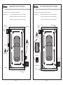
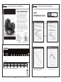
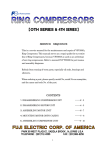
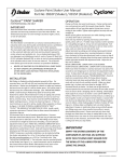
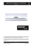
The
Ra
ivers warm filtered
p i d A ir System del
air into your
booth a
t ov e r 1 0 0 0 f p m !
2.5 HP System User Manual
www.dedoesdryingsystems.com
Patent Pending
TABLE OF CONTENTS
RAPID AIR SYSTEM CONTENTS
System Contents
Page 1
Introduction and Overview
Page 2
Operation and Assembly Safety Instructions
Page 4
General Maintenance
Page 5
Spray Booth Diagrams
Page 6
Trouble Shooting
Page 8
System Part Numbers
Page 9
Serial Number and Contact Information
Page 10
Warranty Information
Page 11
Motor Technical Information
Page 12
Product Components:
Two Blower Motors
Two Starter Assemblies or optional VFD Control
Two Hardware Components (Shown assembled)
Components for Two Cart Assemblies or Two Wall Mount Assemblies (Shown assembled)
Two Magnetic Deflectors
CONTACT INFORMATION
Dedoes Industries U.S. Headquarters
1060 W. West Maple Road Walled Lake, MI 48390
Contact Phone Numbers
Sales: 1-248-624-7710 Ext. 222
Technical Support: 1-248-624-7710 Ext.268
Fax: 1-248-624-5080
E-mail: [email protected]
Web Address: www.dedoesdryingsystems.com
Assemblies and configuration may vary from the images above.
Please consult your assembly instructions for more information.
Page 1
INTRODUCTION AND OVERVIEW
INTRODUCTION AND OVERVIEW CONTINUED
Rapid Air Drying System Description:
The specialized air dispensers control both volume and direction of the air flow. Along
The system, located outside the paint booth, generates a high speed air flow vortex of
with creating a high velocity air vortex, the system also increases the temperature and
warm filtered air inside a paint booth to effectively decrease the curing times of both
waterborne and solvent based paints. It is driven by two 2.5 horsepower single-stage
ring compressor electric blower motors, which filter shop air with two 2.0 micron
filtration filters. The system then warms and delivers the air inside the booth at a high
velocity through a piping system which ends with specialized air dispensers that control
lowers the humidity of the paint booth, therefore promoting faster curing times and
improving efficiency.
Available System Features:
-
Electric 230V single phase, 230V three phase, or 460V three phase systems,
independent of the shop air compressor.
the volume and direction of the air.
These specialized air dispensers direct the warm, high velocity air flow along the sides of
-
Valve systems for air flow volume control.
the automobile or the part being painted. The corner air deflectors redirect the air flow
-
Specialized air dispensers for air flow acceleration and directional control produce
along the front and back of the booth to create a vortex effect. See the diagram below.
This airflow dynamic also increases the airflow across the horizontal surfaces such as the
hood, top, and deck lid of the automobile.
Corner Air
Deflectors
Specialized air dispenser
Rapid Air
System
air speeds exceeding 1000 feet per minute at 12 feet away from the dispensers.
-
Two 2.0 micron air filters.
-
Optional Variable Frequency Drive (VFD) Control
Note:
For 230V single phase power, a minimum 30 amp service drop is required for each blower.
Spray Booth Wall
For 230V three phase power, a minimum 20 amp service drop is required for each blower.
For 460V three phase power, a minimum 15 amp service drop is required for each blower.
* All electrical wiring must meet local code requirements.
* Please refer to your electrical contractor for requirements.
Spray Booth Wall
Corner Air
Deflectors
Rapid Air
System
Page 2
Page 3
MAINTENANCE
OPERATION AND SAFETY INSTRUCTIONS
DISCLAIMERS AND SAFETY PRECAUTIONS:
The Dedoes Rapid Air Drying System is intended to be used by trained professionals in industrial
General System Maintenance:
The Rapid Air Drying System requires very little maintenance to retain its efficiency.
To ensure that your system will operate as expected, Dedoes recommends the following
work areas where public and incidental access is prohibited. All operators and repair personnel
care and maintenance:
must read the assembly manuals and be aware of the proper use of the machine and all of its
-
caution markings.
Change the foam and paper filters once per month.
Contact your local Jobber for replacement filters, Dedoes Part Number: P1523
- OSHA approved eye protection must be worn when installing the system.
-
Clean the Blower Assemblies to remove dust and dirt.
(A vacuum is best suited for this.)
- Gloves must be worn when assembling the components and installing the system because the
pipe threads and component edges may be sharp.
- Keep hands and loose clothing away from moving parts.
- Lifting the Blower motor from the packaging will require a crane or two people due to its weight.
- Disconnect electrical power before performing any service on the system.
- The power supply and all electrical connections must conform to all federal, state, and local
Optional Variable Frequency Drive Maintenance:
The VFD operations panel has two filters inside the cabinet.
-
Inspect the filters once per month and replace if necessary.
Contact your local Jobber for replacement filters, Dedoes Part Number: P1683
regulations and be performed by a fully qualified electrician.*
- Any additional piping supplies required to install the system need to be cleaned of oils, metal
shavings, and any other debris before being used for the installation.
- Care must be taken when drilling the holes into the booth wall or any other place necessary to
install the system. The hole locations must be free of any electrical wiring, lighting fixtures,
or gas piping. This includes the holes through the booth and when mounting the starter.
- When using the cart the wheels should be locked into position once the unit is installed to prevent
movement during operation.
- If the supplied carts are not used for the install, the blower motors must be mounted in a safe
and secure manner that supports the weight of the unit and operating motion.
- Units should always be installed where they do not create a hazard to the employees of the
facility and any other person who could be in the area.
* Dedoes assumes no liability if proper wiring is not completed by a licensed electrician.
Page 4
Page 5
STANDARD SPRAY BOOTH DIAGRAM
VFD OPERATED SPRAY BOOTH DIAGRAM
Switches and outlets must be located outside of the booth.
Switches and outlets must be located outside of the booth.
Stand alone unit -
Stand alone unit -
230 Vac with a minimum 20 Amp circuit for three phase
230 Vac with a minimum 20 Amp circuit for three phase
460 Vac with a minimum 15 Amp circuit for three phase
460 Vac with a minimum 15 Amp circuit for three phase
230 Vac with a minimum 30 amp circuit for single phase
230 Vac with a minimum 30 amp circuit for single phase
Manual Ball
Valve
Deflector
Deflector
Rapid Air
System
Rapid Air
System
Power Supply
Power Supply
Starter Box
Power Supply
Starter
Box
Deflector
Rapid Air
System
Spray Booth
Optional
VFD
Control Box
Rapid Air
System
Optional
VFD
Remote Station
Deflector
Spray Booth
Manual Ball
Valve
Page 6
Page 7
COMPLETE SYSTEM PART NUMBERS
TROUBLE SHOOTING
Troubleshooting:
-
Decreased air flow:
RAK2500
2.5hp Rapid Air Single Phase 230 Volt System (Standard Starter)
RAK2520
2.5hp Rapid Air Three Phase 230 Volt System (Standard Starter)
RAK2540
2.5hp Rapid Air Three Phase 460 Volt System (Standard Starter)
RAK2525
2.5hp Rapid Air Three Phase 230 Volt System
(Variable Frequency Drive)
RAK2545
2.5hp Rapid Air Three Phase 460 Volt System
(Variable Frequency Drive)
Change the intake filters.
-
Inadequate air flow upon initial startup:
Check that both ball valves are in the open position.
Check the wiring from the power source to the motor with a volt meter
-
The Blower motor is hot and louder than usual:
Change the intake filters.
-
The Blower motor is whistling:
Check the two 13 mm bolts located at the inlet and exhaust ports on blower motor
and see if they are loose. If so, tighten them.
-
The Rapid Air System is difficult to start or will not start:
Make sure the ball valve is in the open position during start up.
Check the power supply to the system and ensure that all wiring connections are
correct.
Check the circuit breaker to ensure power is supplied to the system.
Depress the red stop/reset button completely to reset each starter box.
For VFD Installations:
-
Trouble Codes:
-
Refer to Fuji-Frenic inverter drive manual for trouble shooting codes.
-
The VFD will not start the system:
-
Be sure the fire suppression interlock is installed. It must be tied into 2190 and 2220
terminals or the VFD will not operate.
Page 8
Page 9
HOW TO LOCATE THE SERIAL NUMBER
When calling the Dedoes Customer Service Department at 1-248-624-7710, we ask that
WARRANTY POLICY
Dedoes Industries Incorporated warrants the Dedoes Rapid Air System against
you have your serial number available. Your serial number will determine which model you
defects due to defective material, design or manufacturing to the end user for a period of One Year from
have, and which parts you may need to repair or replace on your machine. Your serial
the date of purchase based on the Serial Number.
number is located on a label on the side of the Blower Assembly.
This warranty covers all manufactured parts on the products that are defective or damaged.
All products, goods, services and equipment comply with all applicable environmental, safety, design,
and regulatory laws, regulations, customs, and requirements of the region in which they are delivered
and put into service.
This warranty does not cover any items that have been damaged due to mutilation,
alteration, misuse, or abuse. Corrosion due to neglect or chemicals is not covered by this warranty.
Dedoes will not be responsible for loss of time, inconvenience, or other consequential damages. Dedoes
assumes no liability if proper wiring is not completed by a certified electrician.
The warranty is void:
- if the equipment is not properly wired to all applicable codes by a certified electrician
- if the equipment is not installed, assembled, or aligned properly
- if Dedoes parts are not used for repairs or installation
This is the only warranty on Dedoes products and no other expressed warranty by anyone
System Information:
Model Number:
other than Dedoes, in writing, will be binding on the manufacturer. This warranty is transferable from
the location of the original installation of the equipment to any additional installation
First Blower Serial Number:
locations within the warranty time period.
Warranty Return Policy: Under no circumstance should the product or any part there-of be
Second Blower Serial Number:
returned to Dedoes for inspection, replacement, and/or repair without the written consent from
Installation Date:
Dedoes Industries Inc. Returned items must be in original unused condition, unless there is a
manufacturer defect. Please contact Dedoes at 1-248-624-7710 to obtain a Returned Goods
Authorization Number and to discuss other specifics of the return.
Page 10
Page 11
MOTOR TECHNICAL INFORMATION
VFC50
MOTOR TECHNICAL INFORMATION
RING COMPRESSOR
The VFC50 is a single stage ring compressor
with a maximum pressure of 80 in. H2O, a
maximum vacuum of 70 in. H2O, and a
maximum capacity of 154 SCFM. It comes
complete with a direct-drive 2.5 horsepower,
TEFC motor capable of operating on a wide
range of voltages, and on 50 or 60 Hz. A
pilot-duty thermal protector is standard
equipment on all 3 phase and 1 phase models.
All versions have NEMA class B insulation, are
UL recognized, CSA certified, and CE. 575 Volt
units are CSA certified only.
VFC50
PERFORMANCE DATA
PRESSURE
AMPS
(230 V/3 PH)
60 Hz
KEY
50 Hz
VACUUM
KILO
WATTS
Continuous Operation
Permitted
Continuous Operation
Permitted
STATIC
PRESSURE
(Inches of Water)
Flow (SCFM)
SPECIFICATIONS
Model No.
3 Phase
SOUND LEVEL
TEMPERATURE RISE
Amps (Locked
Max. Pressure Max. Vacuum Max. Airflow
Rotor)
Low Voltage/High Voltage
in. H2O
in. H2O
SCFM
200/230
12-11
70-80
80
70
154
200/230
8.5-8
70-75
60
53
130
200-240/400-480
6.9-6.2/3.4-3.1
44-52/22-26
80
70
154
190-230/380-460
5.2-5.4/2.6-2.7
48-56/24-28
60
53
130
Voltage
1 Phase
Flow (SCFM)
Hz
60
50
60
50
60
50
VFC5008-2T
VFC500A-7W
VFC500A-5W
Amps (Max. Rated)
575
2.3
21
80
70
154
SCFM
60
45
45
25
Max. Temp
Rise
°F(°C)
72 (40)
65 (35)
101 (55)
72 (40)
45
119 (65)
Min. Airflow
Weight
lbs. (kg)
Degrees F
Sound Pressure Level (dBA)
Degrees C
97.5 (44)
70.5 (32)
70.5 (32)
ACCESSORIES
Description
Model No.
Vacuum Relief Pressure Relief
Valve
Valve
VV5
PV5
Inlet Filter
Inlet Filter
Cover
F-45
C-45
Note: Maximum allowable time at deadhead is 60 seconds.
Page 12
Exhaust
Inlet
Filter/Receiver Silencer/Muffler
r
R30P1.5
VFY-024A
Frequency (Hz)
Flow (SCFM)
Max. Air Temperature is Value Marked
plus 40 Degrees C Ambient Temperature
*Measured at a distance of 1.0 meter
Page 13
Dedoes Industries U.S. Headquarters
1060 W. West Maple Road Walled Lake, MI 48390
Contact Information:
Sales: 1-248-624-7710 Ext. 222
Technical Support: 1-248-624-7710 Ext.268
Fax: 1-248-624-5080
E-mail: [email protected]
Web Address: www.dedoesdryingsystems.com
For technical support on our products or additional accessories,
please call us at 1-248-624-7710 or visit our web site: www.dedoes.com
PART # P1531 KD RV.9 - 12/08/2014