1
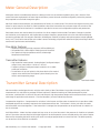
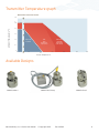
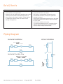
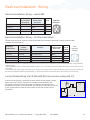
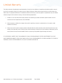
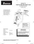
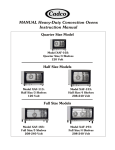
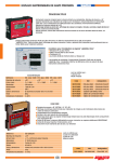
Positive Displacement
Flowmeters
Operational Manual
Model G004
Model G015
For Models
G004, G015, G045, G105, G240
Model G045
Model G240
Model G105
Gear - G Series
Positive Displacement Flow Meters
Max Machinery, Inc. G Series User Manual © Copyright 2013
Rev. 002Q4
1
Table of Contents
Before You Install................................................................................... page 3
Meter General Description................................................................... page 4
Transmitter General Description........................................................ page 5
Meter Specifications............................................................................. page 5
Transmitter Specifications................................................................... page 5
Transmitter Specifications Temp....................................................... page 6
Available Designs................................................................................... page 6
Installation............................................................................................... page 7
Do’s & Don’ts........................................................................................... page 8
Piping Diagram....................................................................................... page 8
Electrical Installation - Wiring........................................................page 9-10
Pressure Drop Charts........................................................................... page 11
Optional Heater Block Details............................................................ page 13
Contact for Repairs & Calibration Services.................................... page 13
Limited Warranty..................................................................................page 14
Custom Instructions for Hazardous Locations/Explosion Proof Housing:
http://www.maxmachinery.com/content/explosion-proof-installation-instructions
DO NOT ATTEMPT TO INSTALL OR START FLOW METER WITHOUT READING THIS ENTIRE MANUAL
Max Machinery, Inc. (MMI) reserves the right to make changes to the product in this Instruction Manual to improve performance, reliability, or
manufacturability. Consequently, contact MMI for the latest available specifications and performance data. Although every effort has been made to
ensure accuracy of the information contained in this Instruction Manual, MMI assumes no responsibility for inadvertent errors.
Max Machinery, Inc. G Series User Manual © Copyright 2013
Rev. 002Q4
2
Before You Install
Thank you for choosing to install a Max Machinery precision flow meter. To ensure the best experience please take a
moment to read through this manual prior to installation.
When you purchased this meter a flow engineer helped determine the best meter for you based on many of the factors
that will be reviewed on the following pages. If you have any questions about installation or operation please don't
hesitate to call Max Machinery, Inc. at 707-433-2662
When you are ready to install there will be a few tools you will need:
Meter Installation:
The meter and transmitter
A signal cable (available from factory)
The display or signal processing device
Indicator Manual
Calibration Certificate
Bypass plumbing supplies
Many Max meters are installed and operate for decades, so having the following information in your records may prove
useful. We have provided this outline as a starting point.
Process Temperatures ____________________________ Fluid Viscosity_____________________________________
Operating Range _________________________________ Line Pressure_____________________________________
Max Sales # or PO #______________________________ Installation Date___________________________________
Meter Model # ___________________________________ Meter Serial #_____________________________________
Transmitter Model #______________________________ Transmitter Serial #________________________________
Notes: ______________________________________________________________________________________________
______________________________________________________________________________________________
______________________________________________________________________________________________
______________________________________________________________________________________________
Max Machinery, Inc. G Series User Manual © Copyright 2013
Rev. 002Q4
3
Meter General Description
While gear meters are traditionally based on a design similar to a conventional hydraulic pump, the G Series of flow
meters has been engineered to increase signal resolution, prevent internal cavitation and greatly reduce the pressure
drop required to move fluid through the gears.
Max flow meters and transmitters are calibrated at the factory as a matched set. This ensures the highest accuracy and
allows for quick setup in the field. For field installations where the transmitter has not been setup with a meter at the
factory, an optional serial interface kit is available to provide full access to all configuration options and parameters.
Solid state sensors are used to detect the position of a driven magnet inside the Max Flow Meter. Changes in position
are tracked by a microprocessor, which generates an output frequency proportional to the flow rate. Advanced signal
processing provides both fine angular resolution (0.36 degrees rotation per pulse) and rapid response (output updated
every 1 ms). The G-Series transmitter uses modern sensor technology coupled with advanced signal processing to deliver
new levels of performance and reliability.
Flow Meter Features
• Capable of operating at high pressures (425 bar/6000 psi).
• Compatible with a wide range of fluid types and viscosities.
• Can operate at high temperatures with a suitable high
temperature transmitter.
Transmitter Features
• High resolution measurement –Analog Output: Configured output ranges to any value within ± 10 Vdc or ± 20 mA.
• Frequency Output: Configured output resolution of 1 to 1000 pulses per revolution.
• Linearization of up to 16 points to fully describe the flow meter’s output curve and achieve the highest system linearity over the
meter’s entire operating range.
Max Model G004
Transmitter General Description
Max transmitters are designed to work with the entire family of Max Flow Meters to provide extremely precise flow
measurement in a cost effective package. Different options of industrial housings or IP66 rated explosion proof
enclosures, combined with a choice of one-part and two-part, high temperature designs with remote electronics cover a
wide range of application environments – from the laboratory to harsh industrial processes.
Compensation Algorithm – Compensates for variations in Hall sensor and flow meter characteristics to provide a stable,
undamped output that accurately represents the instantaneous flow rate. This feature is factory set when the meter
and transmitter are mated together. If the transmitter is changed, the compensation can be performed via a button on
the circuit board.
Anti-Dither Buffer - Masks the false output that may occur at very low flow rates in the presence of vibration or hydraulic
noise. If the meter reverses direction the output signal will be interrupted for a user selected portion of a meter rotation.
Reverse flow exceeding the buffer setting will result in an output proportional to reverse flow rate. The buffer quantity
can be set from 1% to 100% of a revolution.
Max Machinery, Inc. G Series User Manual © Copyright 2013
Rev. 002Q4
4
Meter Specifications
Model
G004 G015 G045 G105 G240
1
Maximum flow rate
Liters/min: 4
15
45 105 240
Gal/min:
1
4
11.9 28 64 Maximum pressure (psi)
|-----------------------414 bar (6000 psi)-----------------------|
see below
2
Maximum temperature
--------------------- 2 part: 225°C (435°F) --------------------
3
Recommended filtration
10 micron
15 micron
20 micron
20 micron
30 micron
Displacement (cc/rev)
1.8
4.2
13.5
38
133
Weight (kg)
1.2 1.8
3.7
7.7
21
Typical k-factor (pulses/cc) 500
200
70
25
7
NPT Port size
1/8”
3/8”
1/2”
3/4”
1” to 280 bar (4000 psi)
SAE Port Size
#4
#6
#8
#10
#16 to 425 bar (6000psi)
For viscosities of 100 cps or more, derate per pressure drop curves for higher viscosities.
Standard transmitter capable to 90°C (195°F)
3
Some materials may have different filter requirements, consult factory.
1
2
Transmitter Specifications
Supply Voltage & Current
Frequency output Analog output
Analog Resolution
5-26 Vdc @ 30 mA typical
12Vdc @ 90 mA typical
24Vdc @ 45 mA typical
Adjustable without recalibration to any range of
+/- 20mA - Models ending in “A1” and “B1”
+/- 10 Vdc - Models ending in “C1” and “D1”)
Frequency Model Specifications
Output (5.0 Volt Supply) Short Circuit Current (1) Output Impedance Rise/Fall Time Output Update Rate(2) Min/Max Frequency Resolution Ambient Temperature Range Maximum Temp, Process Fluid
(20ºC Ambient, 5V supply) Anti-dither Range Default
Signal Filtering No Load 0.00 / 4.80 Volts
2.5K Load to Common 0.00 / 4.60 Volts
2.5K Load to +5 Volts 0.25 / 4.80 Volts
45 mA
100 Ω
0.2 μ Sec
1 ms
0-60 kHz
1 - 1000 pulses/rev
Transmitter (Storage) –40ºC to 85ºC (–40ºF to 185ºF)
Transmitter (Operation) (3) –40ºC to 80ºC (–40ºF to 175ºF)
(Standard Model)
90ºC (195°F)
(High Temp Model)
155ºC (310°F)
(Ultra High Temp Model)225ºC (435°F)
50% Revolution of Meter for unidirectional (software selectable from 1 - 100% of 1 revolution). 2% for bi-directional meters
Software selectable from 1ms to 250ms time constant
(1) Continuous Short Circuit is not recommended. The output current should not exceed 10 mA
(2) Events are seen as output transitions 1 ms after they occur
(3) Temperature of metered fluid will affect transmitter temperature, see graph
Max Machinery, Inc. G Series User Manual © Copyright 2013
Rev. 002Q4
5
Transmitter Temperature graph
Model 29X Transmitter Series
120
110
Ambient Temperature °C
100
80
60
295 & 296
Standard
40
296
High
temperature
2 part pickup
295 & 296
Ultra High
temperature
2 part pickup
20
0
-25
50
100
150
200
225
250
300
Process Temperature °C
Available Designs
G004 Standard
G004 2-Part Pickup
Max Machinery, Inc. G Series User Manual © Copyright 2013
G004 Ex-Proof
Rev. 002Q4
6
Installation
Prior to installing the flow meter remove the storage caps from the ports and look carefully into each port of the meter.
Ensure that no dirt or foreign particles have gotten into the ports of the meter. Make sure that adequate filtration
exists upstream of the flow meter and that no contaminants exist in the line between the filter and flow meter. It is
recommended that the flow meter be connected to the circuit by means of unions close to the flow meter to allow easy
removal.
A by-pass valve should be installed between the inlet and outlet ports in parallel to the flow meter to allow flow through
the system in the event that the flow meter becomes blocked by foreign material.
The preferred orientation for the meter is to place the transmitter to the side of the flow meter. Such an installation
ensures that bubbles will not accumulate within the meter. In a high pressure installation, the compression and
expansion of gas bubbles from the bearing pockets may create undesirable side forces on the gears. Mounting the
meter with the transmitter to the side will purge the air from the meter. This orientation is also preferred as it reduces
the amount of heat that rises from the meter into the transmitter circuitry.
The following items and conditions should be considered:
Line and Bypass Valves: These valves allow filter cleaning or flow meter removal without completely shutting the system
down and draining the lines. They also allow system start up under conditions which could damage the meter; such as:
air in the lines, high temperature materials, or initial line surges.
Filtration: Clearances between the gears and internal wall are typically 0.001” to 0.002”. Any dirt present in the system
can jam or damage the unit. A 10 micron filter (such as a Max 381 Series stainless steel unit) is generally recommended,
although materials with very high viscosities may require a coarser filter. For bidirectional flow applications, use a filter
on each side of the flow meter. Materials with fibrous or non abrasive particulate matter may have to be run without
filters. Follow the recommendation of your Max Sales Engineer or consult our Technical Service Department.
Inlet and Outlet Ports: Use the “IN” port as the inlet for the most predominant flow direction. Install the flow meter on
the discharge side of the pump whenever possible. Excessive vibration at the meter should be avoided.
High Temperatures: Mount the meter so that the transmitter is below or to the side of the meter. This minimizes heat
transfer by convection from the flow meter to the transmitter. The transmitter is the most heat sensitive element in the
system and the transmitter manual should be consulted for specific limits. An optional fluid heater block can be used
on the flow meter to keep it at operating temperature during standby conditions. For substances that are solid at room
temperature, the block may be required to keep the material molten and flowing through the meter.
Clean Plumbing: Before installing the flow meter, clean the inside of the pipe line with compressed air or steam
(especially when using new pipe). Don’t use water, steam, or compressed air on the meter itself!
Max Machinery, Inc. G Series User Manual © Copyright 2013
Rev. 002Q4
7
Do’s & Don’ts
DO:
DON’T:
• Install a bypass line around the meter
• Clean the filter on a regular basis
• Purge air from the meter before operating your system
(Flowing near the meters maximum flow rate for a
given viscosity will purge air bubbles. Tilting, tapping
or shaking the meter at lower flow rates will also
dislodge entrapped air)
• Run water or aqueous solutions through the meter
(except the 234 Series of meters)
• Put steam or compressed air through the meter.
• Disassemble the meter (Air may over-speed and
damage the meter)
• Apply excessive differential pressure across the meter
• Exceed the maximum flow rates or pressure ratings
for your meter
• Let materials solidify in the meter
• Try to pump through the meter if it contains frozen
material. Re-melt the material completely before
trying to pump through the flow meter.
Piping Diagram
Horizontal Installation
Vertical Installation
FLOW
FLOW METER
VALVE 1
VALVE 2
VALVE 2
FILTER
VALVE 3
BYPASS
FLOW METER
Horizontal Two-Way Flow
VALVE 3
BYPASS
FLOW
FLOW METER
VALVE 1
FILTER
VALVE 2
FILTER
FILTER
VALVE 3
VALVE 1
FLOW
BYPASS
Max Machinery, Inc. G Series User Manual © Copyright 2013
Rev. 002Q4
8
Electrical Installation - Wiring
Removal note: The transmitter does not need to be removed from the flow meter for any field servicing or adjustments.
Normally, the flow meter and transmitter are shipped back to the factory for calibration or service as a unit. If the
transmitter needs to be removed from the flow meter for installation, be sure to retighten the transmitter snugly in
order to ensure proper sensor alignment.
Mechanical Installation
1. The transmitter is attached to the flow meter’s threaded magnet shield. Hand tighten only. (~ 3 ft-lb)
2. The transmitter lid has four thread paths. To realign the cable, remove the lid and rotate up to 180° and retighten
using an alternate starting point. Tighten to compress the O-ring seal.
Removal
1. Remove electrical connections
2. Unscrew transmitter, using a wrench if necessary.
WARNING
Installation and removal should only be facilitated by trained personnel
Verify transmitter output type (ANALOG or FREQUENCY) before wiring, inappropriate wiring could
result in damaging the circuit.
Moisture Seal Protection
On all models, the housing is designed as a liquid and vapor-tight enclosure. There is an O—ring seal at the lid of the
housing — these need to be fully seated. A properly sealed transmitter will prevent the formation of damaging moisture
inside the housing.
Turck connector model: The connector is sealed to the lid at the factory and is ready for use.
NPT Model: To ensure a moisture-tight seal, apply appropriate sealant to the threads at installation.
Max Machinery, Inc. G Series User Manual © Copyright 2013
Rev. 002Q4
9
Electrical Installation - Wiring
Electrical Installation: Wiring — Helical 289
NPT Models
Circuit Board
Terminal #
6-Pin Connector
Mating Cable
Wire Color
Pin #
Case Ground
1
Green
A
Common
2
Black
B
Power (+5-24 VDC)
3
Red
C
Pulse Output
4
White
D
Amphenol
Connector
Electrical Installation: Wiring — All other transmitters
The electrical connector versions are pre-wired inside the transmitter and ready to accept a mating cable
(available from the factory).
Frequency
Single Phase
Frequency
Case Ground
Single
Phase
Common
Wiring
Power 5-26 Vdc
Pulse Output
N/A
Frequency
2 phase,
Quadrature
Analog**
Mating Cable
Wire Color
Turck
Pin #
(Male)
Case Ground
Case Ground (Case)
Blue
3
Common
Power 5-26 Vdc
Output Phase A
Output Phase B
Common (Com)
Power * (V+)
Signal Output (-)** (Sig)
Signal Output (+) (Ret)
Black
Brown
White
Grey
4
1
2
5
Turck
Connector
(Female)
4
3
5
1
2
Note: There are no selections or adjustments to be made on the circuit board. The only method of altering the setup parameters is through the Serial
Interface Program.
* Analog transmitters with part numbers 29X-XXX-000 or ending in A/1 or C/1 are 24Vdc power. Part numbers 29X-XXX-100 or ending in B/1 or D/1 are
12Vdc power.
** To minimize noise, analog output transmitters are fully isolated. If your system does not ground the negative signal input you should install a 10k
pull down resistor between Common and Signal Output (-). This will avoid the risk of ground shifts which could drive the signal out of range.
Current Sinking Wiring (Part # 295-600-000 and versions ending with S/1)
A current sinking device is essentially a switch where the transmitter’s output
opens and closes a switch. A positive DC voltage must be applied to the
transmitter's output pin. When the output is triggered, this voltage will be
grounded to zero volts by the transmitter. Use a 5k ohm resistor to limit current
if your system does not have any other means to limit the current into the
transmitter.
V+
PLC
V+
0V
Digital
Input
Out
Turck Pin #2
Transmitter
Max Machinery, Inc. G Series User Manual © Copyright 2013
Rev. 002Q4
10
Pressure Drop Charts
Model G004 Flow Meter
Model G015 Flow Meter
Model G045 Flow Meter
Max Machinery, Inc. G Series User Manual © Copyright 2013
Rev. 002Q4
11
Pressure Drop Charts - continued
Model G105 Flow Meter
Model G240 Flow Meter
Max Machinery, Inc. G Series User Manual © Copyright 2013
Rev. 002Q4
12
Optional Heater Block Details
Temperature probe holes (all models)
1/8" NPT
1/16" NPT
Heater block for G015
(typical)
Liquid trace ports
G004, G015 G045, G105
G240 (Qty 2)
1/4" NPT
3/8" NPT
3/8" NPT
2.262
2.051
3/8" x 1"
3/8" x 1.3"
1/2" x 2.1"
1/2" x 3.1"
1/2" x 4.7"
.1895±.0025
1.55
.376±.001
1.25
Electric Cartridge requirements
G004
G015
G045
G105
G240 (Qty 2)
1/8” NPT
.1275±.0025
.749
.529
0
1/16” NPT
1/4” NPT (2 places)
NOTES:
1: HEATER PORT CLEARANCE IS FOR A PROBE WITH 250 WATT/DENSITY MAX AT 400º F
Contact for Repairs
& Calibration Services
The G Series is not designed for user repair and all such work should be done at the factory or under the direct
supervision of the Max Technical Service Department. Unauthorized repair work may damage the meter and will void the
product warranty. Please make note of model and serial numbers on the flow meter before calling the factory. A return
goods authorization number will be issued if the flow meter has to be sent back for repair.
Max Machinery, Inc. 33A Healdsburg Ave Healdsburg, CA 95448 Phone: 707-433-2662
Fax: 707-433-1818
www.maxmachinery.com
Max Machinery, Inc. G Series User Manual © Copyright 2013
Rev. 002Q4
13
Limited Warranty
The Seller warrants all equipment manufactured by it to be free from defects in materials and workmanship in normal
service for a period of twelve (12) months from the date of shipment. When given prompt notice by the Purchaser, the
Seller shall, in complete fulfillment of its liabilities under this warranty, correct by repair or replacement any such defect
without charge F.O.B. the Seller’s factory, with the following stipulations:
1.
Product is not to be returned to Seller without first obtaining a product-evaluation quote number from our
Customer Service Department at (707) 433-2662.
2. Seller assumes no liability for charges incurred for repairing, removal or replacement, or for repairs made
outside of its factory.
3. Seller reserves the right to inspect products claimed defective under warranty and is the final authority on the
validity of the warranty claim. (Actions that void the warranty include, but are not limited to, disassembly of the
meter, failure to install recommended filtration or passing incompatible liquids through the meter.)
IT IS EXPRESSLY AGREED THAT THIS WARRANTY OR ANY OTHER WARRANTY STATED OR REFERRED TO ON THE
SALES ORDER DOCUMENT IS EXCLUSIVE AND IN LIEU OF ANY OTHER WARRANTY OF MERCHANTABILITY, FITNESS OF
PURPOSE, OR ANY OTHER WARRANTY OF QUALITY, EXPRESS OR IMPLIED.
Max Machinery, Inc. G Series User Manual © Copyright 2013
Rev. 002Q4
14