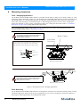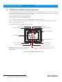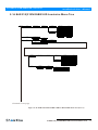
1
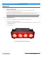
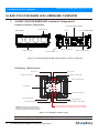
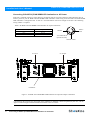
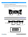
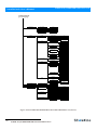
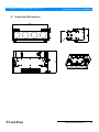
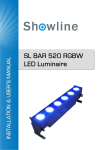
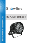
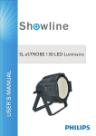
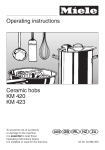
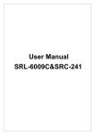
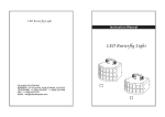
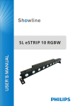
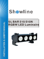
SL BAR 510/510N
RGBW LED Luminaire
Showline Offices
Showline - Dallas
10911 Petal Street
Dallas, TX 75238
Tel: 214-647-7880
Fax: 214-647-8030
Showline - Auckland
19-21 Kawana Street
Northcote, Auckland 0627
New Zealand
Tel: +64 9 481 0100
Fax: +64 9 481 0101
Showline - Europe
Marssteden 152
Enschede 7547 TD
The Netherlands
Tel: +31 53 4500424
Fax: +31 53 4500425
Showline - Asia
Unit C, 14/F, Roxy Industrial Centre
No. 41-49 Kwai Cheong Road
Kwai Chung, N.T., Hong Kong
Tel: +852 2796 9786
Fax: +852 2798 6545
Website:
www.philips.com/showline
The material in this manual is for information purposes only and is subject to change without notice. Showline assumes
no responsiblitity for any errors or omissions which may appear in this manual. For comments and suggestions regarding
corrections and/or updates to this manual, please visit the Showline website at www.philips.com/showline or contact your
nearest Showline office.
Note: Information contained in this document may not be duplicated in full or in part by any person without prior written
approval of Showline. Its sole purpose is to provide the user with conceptual information on the equipment mentioned. The use of
this document for all other purposes is specifically prohibited.
Document Number: SL BAR 510/510N RGBW User’s Manual
Version as of: 17th June, 2014 Rev1.0
SL BAR 510/510N RGBW LED Luminaire installation & User’s Manual
2014 Philips Group. All rights reserved.
SL BAR 510/510N RGBW LED Luminaires
Installation & User’s Manual
Warnings and Notices
When using electrical equipment, basic safety precautions should always be followed including the following:
READ AND FOLLOW ALL SAFETY INSTRUCTIONS.
Do not use outdoors.
Do not mount near gas or electric heaters.
Equipment should be mounted in locations and at heights where it will not readily be subject
to tampering by unauthorized personnel.
The use of accessory equipment not recommended by the manufacturer may cause an unsafe
condition.
Do not use this equipment for other than intended use.
Refer service to qualified personnel.
WARNING: You must have access to a mains circuit breaker or other power disconnect device
before installing any wiring. BE sure that power is disconnected by removing fuses or turning the
mains circuit breaker off before installation. Installing the device with power on may expose you
to dangerous voltages and damage the device. A qualified electrician must perform this installation.
WARNING: Refer to National Electrical Codeand local codes for cable specifications.
Failure to use proper cable can result in damage to equipment or danger to personnel.
WARNING: This equipment is intended for installation in accordance with the Nation Electric
Code and local regulations. It is also intended for installation in indoor applications only. Before
any electrical work is performed, disconnect power at the circuit breaker or remove the fuse to
avoid shock or damage to the control. It is recommended that a qualified electrician perform this
installation.
Additional Resources for DMX512
For more information on installing DMX512 control systems, the following publication is available for purchase
from the United States Institute for Theatre Technology (USITT), "Recommended Practice for DMX512: A Guide
for Users and Installers, 2nd edition" (ISBN: 9780955703522). USITT Contact Information:
USITT
315 South Crouse Avenue, Suite 200
Syracuse, NY 13210-1844
Phone: 1.800.938.7488 or 1.315.463.6463
www.usitt.org
Showline Limited Two-Year Warranty
Showline offers a two-year limited warranty of its luminaires against defects in materials or workmanship from the
date of delivery. A copy of Showline two-year limited warranty containing specific terms and conditions can be
obtained by contacting your local Showline office.
SL BAR 510/510N RGBW LED Luminaires
Installation & User’s Manual
PREFACE
1.
About this Manual
The document provides installation and operation instructions for the following products:
SL BAR 510/510N RGBW LED Luminaire
Please read all instructions before installing or using this product. Retain this manual for future reference.
Additional product information and descriptions may be found on the product specification sheet.
Note: The SL BAR 510/510N RGBW LED Luminaire is universal voltage 100 to 240 VAC (auto-ranging).
2.
Included Items
Each SL BAR 510/510N RGBW LED Luminaire includes the following items:
SL BAR 510/510N RGBW LED Luminaires
PC1BE - AC Power Input Cable (39 inches / 1 meter), Powercon with Bare End* (*Note, user supplies and installs
own AC input connector)
Quick Start Guide
Accessory Yoke Plate
SL BAR 510/510N RGBW LED Luminaire
About this Manual
3
Installation & User’s Manual
SL BAR 510/510N RGBW LED Luminaires
SL BAR 510/510N RGBW LED LUMINAIRE OVERVIEW
1.
SL BAR 510/510N RGBW LED Luminaire Components
Common Luminaire Components
LCD Display / Menu System
Locking Bolts (x2)
Front of Unit
AC Input
AC Output
DMX512 / RDM Input
High Power LEDs
Rear of Unit
DMX512 / RDM Output
Luminaire Mount (x2)
Figure 1: SL BAR 510/510N RGBW LED Luminaire Common Components
LCD Display / Menu System
Edit a Preset
Edit a Chase
Home (menu settings)
DMX512 Addressing
Return to Main Screen
LCD Display
SL BAR 510
DOWN Arrow Button
LEFT Arrow Button
UP Arrow Button
RIGHT Arrow Button
CHECK MARK (Accept) Button
NOTE: Menu rotates with orientation of
luminaire and menu buttons are always in
the same position (with rotation of menu)
To rotate menu 180 degrees from current orientation,
press and hold the two center buttons for 2 seconds.
Figure 2: LCD Display & Menu System
Note: For Menu operation and programming details, refer to "LCD Display and Menu System" on page
.
9.
4
SL BAR 510/510N RGBW LED Luminaire Overview
Installation & User’s Manual
SL BAR 510/510N RGBW LED Luminaires
INSTALLATION AND SET UP
1. Power Requirements
The SL BA R 510/510N RGBW LED Luminaires operate on AC input voltages from 100 to 240 VAC.
WARN ING! SL BAR 510/510N RGBW LED Luminaires do not contain an ON/OFF switch. Always disconnect power
input cable to completely remove power from the luminaire when not in use.
AC Power Operation
When connected to an AC source, the unit operates on 100 to 240 volts AC (+/- 10%, auto-ranging). The luminaire
contains an auto-ranging power supply. Each luminaire can draw up to 110 Watts.
WARN ING! Maximum amount of fixtures that may be daisy-chained is (A) 13 units 100 ~ 120VAC or (B) 32 units
230 ~ 240VAC (15 Amps).
Table 1: SL BAR 510/510N RGBW LED Luminaire Voltage (VAC) vs. Current*
Voltage (AC)
Total Current (A)
100
110
120
130
140
150
160
170
1.10
1.00
0.92
0.84
0.78
0.73
0.68
0.64
Voltage (AC)
180
190
200
210
220
230
240
Total Current (A)
0.61
0.57
0.55
0.52
0.50
0.47
0.45
Note: For wiring of AC input connector, refer to "Connecting SL BAR 510/510N RGBW LED Luminaires to AC
Power" on page 6.
2. Connecting Power
Units can be powered in one of two ways:
Direct connection to a AC power source using an AC input cable. For wiring of AC input connector, refer to
"Connecting SL BAR 510/510N RGBW LED Luminaires to AC Power" on page 6.
Connection from the AC output of another SL BAR 510/510N RGBW LED Luminaire. When using this method, it is
very important not to connect any other type of equipment device.
WARN ING! Only connect other SL BAR 510/510N RGBW LED Luminaires to the AC Output (Thru) connector of a
SL BA R 510/510N RGBW LED Luminaire.
Installation and Set Up
5
Installation & User’s Manual
SL BAR 510/510N RGBW LED Luminaires
Connecting SL BAR 510/510N RGBW LED Luminaires to AC Power
If the unit is supplied with an AC input cable but you did not order an AC input connector, Table 2describes how to
connect power to your SL BAR 510/510N RGBW LED Luminaire. Field wiring of the SL BAR 510/510N RGBW
LED Luminaire is straight forward. A total of 3 wires/conductors need to be brought to the unit. The following
wiring scheme is required:
Table 2: SL BAR 510/510N RGBW LED Luminaire AC Input Connections
Wire Color
Purpose
Brown
Blue
Green/Yellow
Main/Line(100 to 240VAC)
Neutral
Ground (Earth)
Main /
Line
Neutral
AC Connector
(on side of unit)
Ground / Earth
AC Input
AC Output
Luminaire
Figure 3: SL BAR 510/510N RGBW LED Luminaire AC Input & Output Connections
CAUTION: In the event the AC input cable of this luminaire is damaged, it must be replaced, by the user, with an
approved cable through an Authorized Showline Dealer or Service Center.
6
Connecting SL BAR 510/510N RGBW LED Luminaires to AC Power
Installation & User’s Manual
SL BAR 510/510N RGBW LED Luminaires
3. Connecting to the DMX512 Network
Basic DMX512 installation consists of connecting multiple SL BAR 510/510N RGBW LED Luminaires together (up to
32 luminaires) in "daisy-chain" fashion. A cable runs from the control console (or DMX512 control source) to the
DMX connector on the first SL BAR 510/510N RGBW LED Luminaire. Another cable runs from the other DMX
connector on the first unit to a DMX connector on the next SL BAR 510/510N RGBW LED Luminaire (or DMX512
device to be controlled).
Luminaire
DMX512 / RDM
Input Connector
DMX512 / RDM
Output Connector
Figure 4: SL BAR 510/510N RGBW LED Luminaire DMX512 Input / Output Connections
Note: For more information on DMX512 networking and systems, refer to "Additional Resources for DMX512" on
page 1. For SL BAR 510/510N RGBW LED Luminaire DMX Mapping, refer to "DMX CONTROL" on page 16 .
DMX512
(from console or
control device)
DMX512 (out from first
to second luminaire)
DMX512 (out to the next luminaire or DMX512
controlled device)
DMX512 Conections
DMX512 Signal
XLR Pin
Common (Drain)
1
DMX512-
2
DMX512+
3
Note: Remaining pins on each connector are not used.
Figure 5: SL BAR 510/510N RGBW LED Luminaire - DMX512 Connections
Connecting to the DMX512 Network
7
Installation & User’s Manual
SL BAR 510/510N RGBW LED Luminaires
4. Mounting Luminaire
Truss / Hanging Applications
The SL BAR 510/510N RGBW LED Luminaire is provided with the ability to hang via truss hooks, clamps, etc. (sold
separately). Simply attach hook, clamp, etc. to the SL BAR 510/510N RGBW LED Luminaire enclosure assembly in the
provided M10 holes. It is recommended (and may be required by local and national safety codes) to use and install a
safety cable (sold separately) as illustrated in Figure 6. When hanging the fixture, be sure to leave enough space
around the luminaire to allow proper, uninterrupted airflow for cooling and movement. Refer to "Luminaire
Dimensions" on page 36 for spacing (dimensional) requirements.
Note: Mounting hooks, clamps, safety cables, etc. are sold separately or by others. For mounting accessories
available for this product, refer to "Accessories" on page 3.
SAFETY CABLE: Is sold separately and recommended
for all hanging installations and may be required by
national and local codes. Use the safety cable
anchor points for this fixture.
Hook / Clamp
Yoke Plate
Accessory
*Each SL BAR 510/510N RGBW LED STROBE luminaire
includes an accessory Yoke Plate. This can be added
to the luminaire to allow hanging with a single clamp.
Yoke Plate
Bolt(x4)
Flat Washer(x4)
Lock Washer(x4)
Nut(x4)
Mounted with Yoke Plate*
SAFETY CABLE: Is sold separately and recommended
for all hanging installations and may be required by
national and local codes. Use ther safety cable
anchor points for this fixture.
Mounted without Yoke Plate*
Figure 6: Mounting the Fixture - Hanging Applications
Floor Mounting
The SL BAR 510/510N RGBW LED Luminaires are designed to sit directly on its enclosure assembly (base) in a floor
installation application. When used in this type of application, be sure to leave enough space around the luminaire to
allow proper, uninterrupted airflow for cooling and movement.
8
Mounting Luminaire
SL BAR 510/510N RGBW LED Luminaires
Installation & User’s Manual
OPERATION AND PROGRAMMING
1.
LCD Display and Menu System
SL BAR 510/510N RGBW LED Luminaires
The SL BAR 510/510N RGBW LED Luminaire’s LCD Display and Menu System provides local control for accessing
the following fixture’s settings:
Presets (Standard and User Defined)
Color Filter
Effects (Chases - preloaded and user defined)
Strobe / Timing
Settings
Lock Fixture (to prevent changes)
Password
Status
Note: If there are multiple luminaires in a system, changes would need to be made at each LCD Menu as desired. For
SL BAR 510/510N RGBW LED Luminaire menu structure, see "SL BAR 510/510N RGBW LED Luminaire Menu
Tree" on page 11.
Upon power up, the LCD will display the main screen showing the product type/name. If DMX is enabled, the
programmed address will appear after power up.
Operation and Programming
9
Installation & User’s Manual
SL BAR 510/510N RGBW LED Luminaires
2. LCD Display and Menu System Operation
The LCD Display Menu system consists of several categories. Use the Menu Buttons to access and make changes to
the menu items. When the desired menu item is reached, press the desired Menu Button to display the menu options
and to navigate and configure the menu options as required.
To navigate and access menu settings/selections:
Step 1. Make sure unit is powered and turned on.
Step 2. Press the desired button (as shown in Figure 8) to access menu categories.
Step 3. Use UP | DOWN | LEFT | RIGHT arrow buttons to navigate through the various options and settings.
Step 4. Make changes as desired.
Press CHECK MARK (OK) button to accept changes.
Edit a Preset
Edit a Chase
Home (menu settings)
DMX512 Addressing
Return to Main Screen
LCD Display
SL BAR 510
DOWN Arrow Button
LEFT Arrow Button
UP Arrow Button
RIGHT Arrow Button
OK (Check Mark) Button
NOTE: Menu rotates with orientation of Luminaire and
menu buttons are always in the same position (with
rotation of menu)
To rotate menu 180 degrees manually from current
orientation, press and hold the two center buttons for 2
seconds.
Figure 8: LCD Display and Menu System
10
LCD Display and Menu System Operation
Installation & User’s Manual
SL BAR 510/510N RGBW LED Luminaires
3. SL BAR 510/510N RGBW LED Luminaire Menu Tree
MAIN MENU
Preset X(0 thru 31)
Prese t
RGB Mode
All Pixel/Pixel 1-4
Master Intensity
Red
Green
Blue
White
DMX Through
Capture DMX
Master Intensity
Hue
Saturation
Intensity
CCT
DMX Through
Capture DMX
HSIC Mode
0-100%
0-100%
0-100%
0-100%
0-100%
On/Off
Capture DMX
0-100%
0-359 degree
0-100%
0-100%
2700K-6500K
On/Off
Capture DMX
Color Filter (0 thru 43)
Color Filter
Master Intensity
0-100%
Chase
Built-in Chase
1 thru 10
User Chase
Select Chase x(1 thru 8)
Edit Chase x(1 thru 8)
Effects
Master Intensity
Speed
Fade
Edit Step x (1 thru 100)
New Step
Delete Step
0-100%
0.2 S-30 Min
0-100%
Preset X/Color Filter X
All Pixel/Pixel 1-4
RGB Mode
HSIC Mode
Rainbow
Direction
Number of Color
Current Color
Left / Right
1-- 4
1--4
Select Color
Red
Green
Blue
White
Master Intensity
Red
Green
Blue
White
DMX Through
Capture DMX
Master Intensity
Hue
Saturation
Intensity
CCT
DMX Through
Capture DMX
0-100%
0-100%
0-100%
0-100%
0-100%
On/Off
Capture DMX
0-100%
0-359 degree
0-100%
0-100%
2700K-6500K
On/Off
Capture DMX
Color Filter :0-43
0-100%
0-100%
0-100%
0-100%
Continued on next page
Figure 9: SL BAR 510/510N RGBW LED LUMINAIRE Menu Tree(Part 1)
SL BAR 510/510N RGBW LED Luminaire Menu Tree
11
Installation & User’s Manual
SL BAR 510/510N RGBW LED Luminaires
Continued from
previous page
Strobe/Timing
Master Intensity
Strobe
Duration
Intensity Timing
Color Timing
0-100%
xxxx
0--85
0.2 S-60 Min
0.2 S-60 Min
Settings
Security
Enter PassPIN
Level 1 PIN
Level 2 PIN
Level 3 PIN
Power-up Level
****
1111
2222
3333
Locked/Level 1-3
/disable Password
General
Power-up
Preset X(1 thru 32)
Color Filter (1 thru 43)
Chase(1 thru 18)
Last Set
Master Mode
Slave Mode
Normal
Incandescent
Reduce
Mode
DIM Response
Dimming Curve
(DMX 8Bit)
Calibration
Fan Control
Factory Default
Protected
Load Factory
DMX
DMX Enable
Address
Map
linear
Square
S-Curve
PL-Curve
OFF
ON
Auto
OFF
No
Preset & Chase
No
Yes
Enable
Disable
1 to 512
RGBW 8-bit Mode
RGBW 8-bit Group Mode
Simple 8-bit Mode
Simple 8-bit Group Mode
RGBW 16-bit Mode
RGBW 16-bit Group Mode
When no DMX
LED Group
Flip Display
Display
Off Time
Language Select
HSIC Mode
HSIC Group Mode
Off
Hold
Power Up
Last Action
1/2/4
No
Yes
Auto
On/30S/1Min/
5Min/10Min
English
Lock Fixture
LOCK Are you sure?
Password
Enter Pass PIN
Status
Pixel 1-4
LED
Current Level
Master Intensity
Red
Green
Blue
White
0-100%
0-100%
0-100%
0-100%
0-100%
Temperature
Temperature
Warning Low
Warning High
Min_Value
Max_Value
Max Intensity
RDM UID
Firmware Version
xx Celsius degree
83 Celsius degree
86 Celsius degree
xx Celsius degree
xx Celsius degree
0-100%
0X000000000000
Rev 0.0
Other Information
Yes(to lock Fixture)
No
Level 1-3
Figure 10: SL BAR 510/510N RGBW LED LUMINAIRE Menu Tree(Part 2)
12
SL BAR 510/510N RGBW LED Luminaire Menu Tree
SL BAR 510/510N RGBW LED Luminaires
Installation & User’s Manual
4. Quick Selection Buttons
When in Manual Mode, the SL BAR 510/510N RGBW’s features can be accessed via the on-board LCD menu system
or via three quick select buttons:
Edit a Preset Button
Edit a Chase Button
DMX Address Button
Edit a Preset Button
Edit a Preset
To edit and save a preset:
Step 1. Press Edit a Preset button. Current preset will be shown.
Edit a Preset
H
S
I
C
Step 2. Use LEFT and RIGHT arrow buttons to scroll through all presets.
12%
0%
43%
HSI Mode
Step 3. Once at desired preset, use UP and DOWN arrows to access
(highlight) preset parameters. Once in desired parameter, use LEFT
and RIGHT arrow buttons to adjust parameter value as desired.
Step 4. Once all values are adjusted as desired, press OK (Check Mark) button.
Step 5. Save preset menu option will appear. Use LEFTand RIGHT arrow buttons to select preset number.
Step 6. If saving preset, press OK (Check Mark) button. Confirm choice.
Step 7. Preset is now saved.
Edit a Chase Button
Edit a Chase
To edit and save a chase:
Step 1. Press Edit a Chase button. Current chase will be shown.
Built In Chase 8
Step 2. Use LEFT and RIGHT arrow buttons to scroll through all chases
(Built In and User Chases).
Total Steps
24
Speed
8
Fade
S
70%
Note: For Built In Chases, only the Speed and Fade parameters may be
changed and saved. For User Chases, Chase Number, Total Steps, Speed, and
Fade Parameters may be changed and saved.
Step 3. Once at desired chase, use UP and DOWN arrows to access (highlight ) chase parameters. Once in desired
parameter, use LEFT and RIGHT arrow buttons to adjust parameter value as desired.
Step 4. Once all values are adjusted as desired, press OK(Check Mark) button.
Step 5. Save chase menu option will appear. Use LEFT and RIGHT arrow buttons to select chase number.
Step 6. If saving chase, press OK (Check Mark) button. Confirm choice.
Step 7. Chase is now saved.
DMX Address Button
DMX Address
To edit and save a DMX address:
Step 1. Press DMX Address button. Current DMX Address will be shown.
Address
255
Step 2. Press OK (Check Mark) button to highlight a digit in the DMX
address.
Step 3. Use LEFT and RIGHT arrow buttons to scroll through all digits.
Step 4. Once at desired digit, use UP and DOWN arrows to change
highlighted digit. Once digit is set, use LEFT and RIGHT arrow buttons to set other digits in DMX address.
Step 5. Once all digits are set in DMX address, press OK(Check Mark) button.
Step 6. DMX will display and is saved.
Quick Selection Buttons
13
Installation & User’s Manual
SL BAR 510/510N RGBW LED Luminaires
Through the menu, you are able to select one of four dimming curves:
Linear Curve
PL_Curve
S_Curve
Square Curve
Lumen Output
PL_Curve*
Lumen Output
Linear Curve
DMX Value
DMX Value
*PL Curve follows the dimming curve of Philips Selecon
PL series LED luminaires.
S_Curve
Lumen Output
Lumen Output
Square Curve
DMX Value
DMX Value
Figure 11: SL BAR 510/510N RGBW LED Luminaire Dimmer Curves
14
Dimming Curve Selection
Installation & User’s Manual
SL BAR 510/510N RGBW LED Luminaires
6. Master / Slave Operational Mode
The Master / Slave Operational Mode allows one SL BAR 510/510N RGBW LED Luminaire to act as the "Master" unit
and all other connected units are controlled by this unit. When a unit is set to "Slave" mode, it will only listen to and
follow any commands sent from a "Master" unit. Only one "Master" unit is allowed in this type of operation.
To Setup a master/slave network:
Step 1. Set the first device in the DMX512 chain to Master Mode through the unit’s menu system.
Step 2. Set all other connected units to Slave Mode.
Step 3. The master unit can be controlled via DMX512, RDM or through standalone operation (self-contained
network utilizing on-board effects). The salve units will mimic the master unit’s operation in all cases.
Note: For more information on DMX512 networking and systems, refer to "Additional Resources for DMX512" on
page 1. For SL BAR 510/510N RGBW LED Luminaire DMX Mapping, refer to "DMX CONTROL" on page 16.
Master Unit
Slave Unit
Slave Unit
DMX512
(from console or
control device)
DMX512 (out from first
to second luminaire)
DMX512 (out to the next luminaire or DMX512
controlled device)
Figure 12: SL BAR 510/510N RGBW LED Luminaire - Master / Slave Configuration
Master / Slave Operational Mode
15
Installation & User’s Manual
SL BAR 510/510N RGBW LED Luminaires
DMX CONTROL
This section contains information for operating the luminaire using DMX control in Simple 8-bit, RGBW 8-bit,
RGBW 16-bit or HSIC (Hue, Saturation, Intensity and Color Correction) modes. For Menu options and detailed
information, see "LCD Display and Menu System” on page 9.
Note: These tables assume a DMX start address of 1. When a different starting address is used, this address becomes
channel 1 function and other functions follow in sequence.
1.
SL BAR 510/510N RGBW LED Luminaire DMX Mapping
Simple 8-Bit Mode
Table 3 provides DMX channel mapping of all DMX512 control values when the SL BAR 510/510N RGBW LED
Luminaire is in simple 8-bit DMX512 mode (as set by the luminaire’s menu system).
Table 3: SL BAR 510/510N RGBW LED Luminaire DMX Channel Mapping (Simple 8 - Bit Mode)
DMX
Channel
Parameter
1
Master Intensity
0 - 255
0 - 100%
0
2
Strobe
0 - 255
0 - 100%
0
Range DMX
Range%
Description
Default
8 bit control for Intensity of LED settings.
Controls strobe operations as follows . . .
Open
Closed
Slow Rand
= DMX 3 - 5
= DMX 6 - 7
Med Rand
= DMX 8 - 10
Fast Rand
= DMX 11 - 12
Strobe Range
= DMX 13 - 127 (fastest)
Pulse + Slow Rand
16
= DMX 0 - 2
= DMX 128 - 129
Pulse + Med Rand
= DMX 130 - 131
Pulse + Fast Rand
= DMX 132 - 133
Pulse + Range
= DMX 134 - 191
Pulse - Slow Rand
= DMX 192 - 193
Pulse - Med Rand
= DMX 194 - 195
Pulse - Fast Rand
= DMX 196 - 197
Pulse - Range
= DMX 198 - 255
3
Red 1-4
0 - 255
0 - 100%
0
8 bit control of Red LEDs from 0 to full.
4
Green 1-4
0 - 255
0 - 100%
0
8 bit control of Green LEDs from 0 to full.
5
Blue 1-4
0 - 255
0 - 100%
0
8 bit control of Blue LEDs from 0 to full.
6
White 1-4
0 - 255
0 - 100%
0
8 bit control of White LEDs from 0 to full.
DMX Control
Installation & User’s Manual
SL BAR 510/510N RGBW LED Luminaires
2. Simple 8Bit Group Mode
Table 4 provides DMX channel mapping of all DMX512 control values when the SL BAR 510/510N RGBW LED
Luminiare is operated in various Simple 8-bit DMX512 Group Control Modes.
Table 4: SL BAR 510/510N RGBW LED Luminaire DMX Channel Mapping (Simple 8Bit Group Mode)
RGBW Simple 8 BIT MODE
DMX CHANNEL
1
2
3
4
5
6
7
8
9
10
11
12
13
14
15
16
17
18
4 Group Mode
Master Intensity
2 Group Mode
Master Intensity
1 Group Mode
Master Intensity
S trobe
S trobe
S trobe
Re d_1
Re d_1-2
Re d_1-4
Gre e n_1
Gre e n_1-2
Gre e n_1-4
Blue _1
Blue _1-2
Blue _1-4
White _1
White _1-2
White _1-4
Re d_2
Re d_3-4
Gre e n_2
Gre e n_3-4
Blue _2
Blue _3-4
White _2
White _3-4
Re d_3
Gre e n_3
Blue _3
White _3
Re d_4
Gre e n_4
Blue _4
White _4
Simple 8Bit Group Mode
17
Installation & User’s Manual
SL BAR 510/510N RGBW LED Luminaires
3. RGBW 8 - Bit Mode
Table 5 provides DMX channel mapping of all DMX512 control values when the SL BAR 510/510N RGBW LED
Luminaire is in RGBW 8-bit DMX512 mode (as set by the luminaire’s menu system).
Table 5: SL BAR 510/510N RGBW LED Luminaire DMX Channel Mapping (RGBW 8-Bit Mode)
DMX
Channel
Parameter
Range DMX
Range%
Default
1
Master Intensity
0 - 255
0 - 100%
0
2
Color Presets
0 - 255
0 - 100%
0
Description
8 bit control for Intensity of LED settings.
Variable color Presets as follows . . .
Channel OFF (disabled)
Preset 0 (OFF)
Preset 1
Preset 2
Preset 3
Preset 4
Preset 5
Preset 6
Preset 7
Preset 8
Preset 9
Preset 10
Preset 11
Preset 12
Preset 13
Preset 14
Preset 15
Preset 16
Preset 17
Preset 18
Preset 19
Preset 20
Preset 21
Preset 22
Preset 23
Preset 24
Preset 25
Preset 26
Preset 27
Preset 28
Preset 29
Preset 30
Preset 31
CF_0_Color OFF
CF_1_White 10000K
CF_2_White 8000K
CF_3_White 6500K
CF_4_White 5600K
CF_5_White 5000K
CF_6_White 4500K
CF_7_White 4000K
CF_8_White 3200K
CF_9_White 3000K
CF_10_White 2700K
18
RGBW 8 - Bit Mode
DMX 0 - 4
DMX 5 - 6
DMX 7 - 8
DMX 9 - 10
DMX 11 - 12
DMX 13 - 14
DMX 15 - 16
DMX 17 - 18
DMX 19 - 20
DMX 21 - 22
DMX 23 - 24
DMX 25 - 26
DMX 27 - 28
DMX 29 - 30
DMX 31 - 32
DMX 33 - 34
DMX 35 - 36
DMX 37 - 38
DMX 39 - 40
DMX 41 - 42
DMX 43 - 44
DMX 45 - 46
DMX 47 - 48
DMX 49 - 50
DMX 51 - 52
DMX 53 - 54
DMX 55 - 56
DMX 57 - 58
DMX 59 - 60
DMX 61 - 62
DMX 63 - 64
DMX 65 - 66
DMX 67 - 68
DMX 69 - 70
DMX 71 - 72
DMX 73 - 74
DMX 75 - 76
DMX 77 - 78
DMX 79 - 80
DMX 81 - 82
DMX 83 - 84
DMX 85 - 86
DMX 87 - 88
DMX 89 - 90
Installation & User’s Manual
SL BAR 510/510N RGBW LED Luminaires
Table 5: SL BAR 510/510N RGBW LED Luminaire DMX Channel Mapping (RGBW 8-Bit Mode)
DMX
Channel
2
Parameter
Range DMX
Range%
Default
Color Presets
0 - 255
0 - 100%
0
Description
CF_11_Moroccan Pink
CF_12_Pink
DMX 91 - 92
DMX 93 - 94
CF_13_Flesh Pink
DMX 95 - 96
CF_14_Bright Rose
DMX 97 - 98
CF_15_Follies Pink
DMX 99 - 100
CF_16_Fuchsia Pink
DMX 101 - 102
CF_17_Surprise Pink
DMX 103 - 104
CF_18_Congo Blue
DMX 105 - 106
CF_19_Blue
DMX 107 - 108
CF_20_Virgin Blue
DMX 109 - 110
CF_21_Midnight Maya
CF_22_Dluble C.T Blue
DMX 111 - 112
DMX 113 - 114
CF_23_Slate Blue
DMX 115 - 116
CF_24_Regal Blue
DMX 117 - 118
CF_25_Fullt C.T Blue
CF_26_Steel Blue
DMX 119 - 120
DMX 121 - 122
CF_27_Lighter Blue
DMX 123 - 124
CF_28_Cyan
DMX 125 - 126
CF_29_Marine Blue
DMX 127 - 128
CF_30_Soft Green
DMX 129 - 130
CF_31_Moss Green
DMX 131 - 132
CF_32_Green
DMX 133 - 134
CF_33_Fem Green
DMX 135 - 136
CF_34_JAS Green
DMX 137 - 138
CF_35_Pale Green
DMX 139 - 140
CF_36_Spring Yellow
DMX 141 - 142
CF_37_Yellow
DMX 143 - 144
CF_38_Deep Amber
DMX 145 - 146
CF_39_Chrome Orange
DMX 147 - 148
CF_40_Orange
DMX 149 - 150
CF_41_Magenta
DMX 151 - 152
CF_42_Flame Red
DMX 153 - 154
CF_43_Purple
DMX 155 - 156
Rotate CW Fast →Slow
DMX 157 - 171
Rotate ACW Slow →Fast
DMX 172 - 186
Random Color Fast →Slow
DMX 187 - 201
RGBW 8 - Bit Mode
19
Installation & User’s Manual
SL BAR 510/510N RGBW LED Luminaires
Table 5: SL BAR 510/510N RGBW LED Luminaire DMX Channel Mapping (RGBW 8-Bit Mode)
DMX
Channel
2
3
Parameter
Range DMX
Range%
0 - 255
0 - 100%
Color Presets
Strobe
0 - 255
0 - 100%
Default - recommended console
default values
Description
0
Chase1
DMX 202 - 204
Chase2
DMX 205 - 207
Chase3
DMX 208 - 210
Chase4
DMX 211 - 213
Chase5
DMX 214 - 216
Chase6
DMX 217 - 219
Chase7
DMX 220 - 222
Chase8
DMX 223 - 225
Chase9
DMX 226 - 228
Chase10
DMX 229 - 231
User Chase1
DMX 232 - 234
User Chase2
DMX 235 - 237
User Chase3
DMX 238 - 240
User Chase4
DMX 241 - 243
User Chase5
DMX 244 - 246
User Chase6
DMX 247 - 249
User Chase7
DMX 250 - 252
User Chase8
DMX 253 - 255
Controls strobe operations as follows . . .
DMX0
Open
Closed
Slow Rand
20
RGBW 8 - Bit Mode
0 - 255
0 - 100%
0
= DMX 6 - 7
= DMX 8 - 10
Fast Rand
= DMX 11 - 12
Strobe Range
= DMX 13 - 127 (fastest)
= DMX 128 - 129
Pulse + Med Rand
= DMX 130 - 131
Pulse + Fast Rand
= DMX 132 - 133
Pulse + Range
= DMX 134 - 191
Pulse - Slow Rand
Duration
= DMX 3 - 5
Med Rand
Pulse + Slow Rand
4
= DMX 0 - 2
= DMX 192 - 193
Pulse - Med Rand
= DMX 194 - 195
Pulse - Fast Rand
= DMX 196 - 197
Pulse - Range
= DMX 198 - 255
Strobe's duration,Range is 0-85
0
= DMX 0
1
= DMX 1 - 3
x
= (DMX Value-1)/3+1
85
= DMX 253-255
Installation & User’s Manual
SL BAR 510/510N RGBW LED Luminaires
Table 5: SL BAR 510/510N RGBW LED Luminaire DMX Channel Mapping (RGBW 8-Bit Mode)
DMX
Channel
5
Parameter
Timing
Range DMX
Range%
Default - recommended console
default values
0 - 255
0 - 100%
255
Description
Allows for timing control of intensity, color, and zoom
parameters. Channel should default to 255 for
smoothest actions using console and/or manual
fades. - See Timing Chart for more details.
6
Control
0 - 255
0 - 100%
0
functions of the SL Series products. Set control
channel value to desired action,Hold value for at
least 5 seconds ,then turn to 0.
Set control channel value to 0 without any scaling.
Default Setting on Console
= DMX 0-4
DIM Response _Normal
= DMX 5 - 9
DIM Response_Incandescent
= DMX 10 - 14
Dimming Curve_linear
= DMX 30 - 34
Dimming Curve_Square
= DMX 35- 39
Dimming Curve_S-Curve
= DMX 40 - 44
Dimming Curve_PL-Curve
Calibration_OFF
Calibration_ON
Fan_Auto
= DMX 45 - 49
= DMX 70 - 74
= DMX 75 - 79
= DMX 80 - 84
Fan_Off
= DMX 85 - 89
Reserves( Future use)
= DMX 90 - 250
7
Red 1-4
0 - 255
0 - 100%
0
8 bit control of Red LEDs from 0 to full.
8
Green 1-4
0 - 255
0 - 100%
0
8 bit control of Green LEDs from 0 to full.
9
Blue 1-4
0 - 255
0 - 100%
0
8 bit control of Blue LEDs from 0 to full.
10
White 1-4
0 - 255
0 - 100%
0
8 bit control of White LEDs from 0 to full.
RGBW 8 - Bit Mode
21
Installation & User’s Manual
4.
SL BAR 510/510N RGBW LED Luminaires
RGBW 8Bit Group Mode
Table 6 provides DMX channel mapping of all DMX512 control values when the SL BAR 510/510N RGBW LED
Luminiare is operated in various RGBW8-bit Group Control Modes.
Table 6: SL BAR 510/510N RGBW LED Luminaire DMX Channel Mapping (RGBW 8 Bit Group Mode)
RGBW 8 BIT MODE
DMX CHANNEL
1
2
3
4
5
6
7
8
9
10
11
12
13
14
15
16
17
18
19
20
21
22
22
RGBW 8Bit Group Mode
4 Group Mode 2 Group Mode
1 Group Mode
Master Intensity
Master Intensity
Master Intensity
Color Presets
Color Presets
Color Presets
Strobe
Strobe
Strobe
Duration
Duration
Duration
Timing
Timing
Timing
Control
Red_1
Control
Red_1-2
Control
Red_1-4
Green_1
Green_1-2
Green_1-4
Blue_1
Blue_1-2
Blue_1-4
White_1-4
White_1
White_1-2
Red_2
Red_3-4
Green_2
Green_3-4
Blue_2
Blue_3-4
White_2
White_3-4
Red_3
Green_3
Blue_3
White_3
Red_4
Green_4
Blue_4
White_4
Installation & User’s Manual
SL BAR 510/510N RGBW LED Luminaires
5. RGBW 16 - Bit Mode
Table 7 provides DMX channel mapping of all DMX512 control values when the SL BAR 510/510N RGBW LED
Luminaire is in RGBW 16-bit DMX512 mode (as set by the luminaire’s menu system).
Table 7: SL BAR 510/510N RGBW LED Luminaire DMX Channel Mapping (RGBW 16-Bit Mode)
DMX
Channel
Parameter
1
Master Intensity High
2
Master Intensity Low
3
Color Presets
Default - recommended console
default values
Range DMX
Range%
0 - 65535
0 - 100%
0
0 - 255
0 - 100%
0
Description
16bit control for Intensity of LED settings.
Variable color Presets as follows . . .
Channel OFF (disabled)
Preset 0 (OFF)
DMX 0 - 4
DMX 5 - 6
Preset 1 (Primary Red)
DMX 7 - 8
Preset 2 (Primary Green)
DMX 9 - 10
Preset 3 (Primary Blue)
DMX 11 - 12
Preset 4 (Orange) DMX 13 - 14
Preset 5 (Pink)
DMX 15 - 16
Preset 6 (Yellow) DMX 17 - 18
Preset 7 (Magenta) DMX 19 - 20
Preset 8 (Day light Blue)
DMX 21 - 22
Preset 9 (Warm White 3200K)
DMX 23 - 24
Preset 10 (Cool White 5600K)
DMX 25 - 26
DMX 27 - 28
Preset 11
DMX 29 - 30
Preset 12
Preset 13
DMX 31 - 32
Preset 14
DMX 33 - 34
Preset 15
DMX 35 - 36
DMX 37 - 38
Preset 16
Preset 17
DMX 39 - 40
Preset 18
DMX 41 - 42
Preset 19
DMX 43 - 44
Preset 20
DMX 45 - 46
DMX 47 - 48
Preset 21
DMX 49 - 50
Preset 22
Preset 23
DMX 51 - 52
Preset 24
DMX 53 - 54
Preset 25
DMX 55 - 56
DMX 57 - 58
Preset 26
Preset 27
DMX 59 - 60
Preset 28
DMX 61 - 62
Preset 29
DMX 63 - 64
Preset 30
DMX 65 - 66
DMX 67 - 68
Preset 31
CF_0_Color OFF
DMX 69 - 70
CF_1_White 10000K
DMX 71 - 72
CF_2_White 8000K
DMX 73 - 74
CF_3_White 6500K
DMX 75 - 76
CF_4_White 5600K
DMX 77 - 78
CF_5_White 5000K
DMX 79 - 80
CF_6_White 4500K
DMX 81 - 82
CF_7_White 4000K
DMX 83 - 84
CF_8_White 3200K
DMX 85 - 86
CF_9_White 3000K
DMX 87 - 88
CF_10_White 2700K
DMX 89 - 90
SL BAR 510/510N RGBW LED Luminaire DMX Mapping
23
Installation & User’s Manual
SL BAR 510/510N RGBW LED Luminaires
Table 7: SL BAR 510/510N RGBW LED Luminaire DMX Channel Mapping (RGBW 16-Bit Mode)
DMX
Channel
3
Parameter
Range DMX
Range%
0 - 255
0 - 100%
Color Presets
Default - recommended console
default values
0
Description
CF_11_Moroccan Pink
CF_12_Pink
CF_13_Flesh Pink
DMX 95 - 96
CF_14_Bright Rose
DMX 97 - 98
CF_15_Follies Pink
DMX 99 - 100
CF_16_Fuchsia Pink
DMX 101 - 102
CF_17_Surprise Pink
DMX 103 - 104
CF_18_Congo Blue
CF_19_Blue
CF_20_Virgin Blue
CF_21_Midnight Maya
CF_22_Dluble C.T Blue
DMX 109 - 110
DMX 111 - 112
DMX 113 - 114
DMX 115 - 116
CF_24_Regal Blue
DMX 117 - 118
CF_26_Steel Blue
CF_27_Lighter Blue
CF_28_Cyan
DMX 119 - 120
DMX 121 - 122
DMX 123 - 124
DMX 125 - 126
CF_29_Marine Blue
DMX 127 - 128
CF_30_Soft Green
DMX 129 - 130
CF_31_Moss Green
DMX 131 - 132
CF_32_Green
DMX 133 - 134
CF_33_Fem Green
DMX 135 - 136
CF_34_JAS Green
DMX 137 - 138
CF_35_Pale Green
DMX 139 - 140
CF_36_Spring Yellow
DMX CONTROL
DMX 105 - 106
DMX 107 - 108
CF_23_Slate Blue
CF_25_Fullt C.T Blue
24
DMX 91 - 92
DMX 93 - 94
DMX 141 - 142
CF_37_Yellow
DMX 143 - 144
CF_38_Deep Amber
DMX 145 - 146
CF_39_Chrome Orange
DMX 147 - 148
CF_40_Orange
DMX 149 - 150
CF_41_Magenta
DMX 151 - 152
CF_42_Flame Red
DMX 153 - 154
CF_43_Purple
DMX 155 - 156
Rotate CW Fast →Slow
DMX 157 - 171
Rotate ACW Slow →Fast
DMX 172 - 186
Random Color Fast →Slow
DMX 187 - 201
Installation & User’s Manual
SL BAR 510/510N RGBW LED Luminaires
Table 7: SL BAR 510/510N RGBW LED Luminaire DMX Channel Mapping (RGBW 16-Bit Mode)
DMX
Channel
3
4
Parameter
Color Presets
Strobe
Range DMX
Range%
0 - 255
0 - 100%
0 - 255
0 - 100%
Default - recommended console
default values
Description
0
Chase1
DMX 202 - 204
Chase2
DMX 205 - 207
Chase3
DMX 208 - 210
Chase4
DMX 211 - 213
Chase5
DMX 214 - 216
Chase6
DMX 217 - 219
Chase7
DMX 220 - 222
Chase8
DMX 223 - 225
Chase9
DMX 226 - 228
Chase10
DMX 229 - 231
User Chase1
DMX 232 - 234
User Chase2
DMX 235 - 237
User Chase3
DMX 238 - 240
User Chase4
DMX 241 - 243
User Chase5
DMX 244 - 246
User Chase6
DMX 247 - 249
User Chase7
DMX 250 - 252
User Chase8
DMX 253 - 255
Controls strobe operations as follows . . .
DMX0
Open
Closed
Slow Rand
0 - 255
0 - 100%
0
= DMX 6 - 7
= DMX 8 - 10
Fast Rand
= DMX 11 - 12
Strobe Range
= DMX 13 - 127 (fastest)
= DMX 128 - 129
Pulse + Med Rand
= DMX 130 - 131
Pulse + Fast Rand
= DMX 132 - 133
Pulse + Range
= DMX 134 - 191
Pulse - Slow Rand
Duration
= DMX 3 - 5
Med Rand
Pulse + Slow Rand
5
= DMX 0 - 2
= DMX 192 - 193
Pulse - Med Rand
= DMX 194 - 195
Pulse - Fast Rand
= DMX 196 - 197
Pulse - Range
= DMX 198 - 255
Strobe's duration,Range is 0-85
0
= DMX 0
1
= DMX 1 - 3
x
= (DMX Value-1)/3+1
85
= DMX 253-255
SL BAR 510/510N RGBW LED Luminaire DMX Mapping
25
Installation & User’s Manual
SL BAR 510/510N RGBW LED Luminaires
Table 7: SL BAR 510/510N RGBW LED Luminaire DMX Channel Mapping (RGBW 16-Bit Mode)
DMX
Channel
Parameter
Range DMX
Range%
Default - recommended console
default values
6
Intensity Timing
0 - 255
0 - 100%
255
7
Color Timing
0 - 255
0 - 100%
255
8
Control
0 - 255
0 - 100%
0
Description
Allows for timing control of intensity, color, and zoom
parameters. Channel should default to 255 for
smoothest actions using console and/or manual
fades. - See Timing Chart for more details.
Allows for timing control of colors. Channel should
default to 255 for smoothest actions using console
and/or manual fades. - See Timing Chart for more
details.
functions of the SL Series products. Set control
channel value to desired action,Hold value for at
least 5 seconds ,then turn to 0.
Set control channel value to 0 without any scaling.
Default Setting on Console
= DMX 5 - 9
DIM Response_Incandescent
= DMX 10 - 14
Dimming Curve_linear
= DMX 30 - 34
Dimming Curve_Square
= DMX 35- 39
Dimming Curve_S-Curve
= DMX 40 - 44
Dimming Curve_PL-Curve
Calibration_OFF
Calibration_ON
9
Red 1-4 High
10
Red 1-4 Low
11
Green 1-4 High
12
Green 1-4 Low
13
14
15
16
26
= DMX 0-4
DIM Response _Normal
= DMX 45 - 49
= DMX 70 - 74
= DMX 75 - 79
Fan_Auto
= DMX 80 - 84
Fan_Off
= DMX 85 - 89
Reserves( Future use)
= DMX 90 - 250
0 - 65535
0 - 100%
0
16bit control of Red LEDs from 0 to full.
0 - 65535
0 - 100%
0
16bit control of Green LEDs from 0 to full.
Blue 1-4 High
Blue 1-4 Low
0 - 65535
0 - 100%
0
16bit control of Blue LEDs from 0 to full.
White 1-4 High
White 1-4 Low
0 - 65535
0 - 100%
0
16bit control of White LEDs from 0 to full.
DMX CONTROL
Installation & User’s Manual
SL BAR 510/510N RGBW LED Luminaires
6. RGBW 16Bit Group Mode
Table 8 provides DMX channel mapping of all DMX512 control values when the SL BAR 510/510N RGBW LED
Luminiare is operated in various RGBW 16bit DMX512 Group Control Modes.
Table 8: SL BAR 510/510N RGBW LED Luminaire DMX Channel Mapping (RGBW 16Bit Group Mode)
DMX CHANNEL
1
2
3
4
5
6
7
8
9
10
11
12
13
14
15
16
17
18
19
20
21
22
23
24
25
26
27
28
29
30
31
32
33
34
35
36
37
38
39
40
RGBW 16 BIT MODE
4 Group MODE
2 Group MODE
1 Group MODE
Master Intensity - High
Master Intensity - High
Master Intensity - High
Master Intensity - Low
Master Intensity - Low
Master Intensity - Low
Color Presets
Color Presets
Color Presets
Strobe
Strobe
Strobe
Duration
Duration
Duration
Intensity Timing
Intensity Timing
Intensity Timing
Color Timing
Color Timing
Color Timing
Control
Control
Control
Red_1 - High Byte
Red_1-2 - High Byte
Red_1-4 - High Byte
Red_1 - Low Byte
Red_1-2 - Low Byte
Red_1-4 - Low Byte
Green_1 - High Byte
Green_1-2 - High Byte
Green_1-4 - High Byte
Green_1 - Low Byte
Green_1-2 - Low Byte
Green_1-4 - Low Byte
Blue_1 - High Byte
Blue_1-2 - High Byte
Blue_1-4 - High Byte
Blue_1 - Low Byte
Blue_1-2 - Low Byte
Blue_1-4 - Low Byte
White_1 - High Byte
White_1-2 - High Byte
White_1-4 - High Byte
White_1 - Low Byte
White_1-2 - Low Byte
White_1-4 - Low Byte
Red_2 - High Byte
Red_3-4 - High Byte
Red_2 - Low Byte
Red_3-4 - Low Byte
Green_2 - High Byte
Green_3-4 - High Byte
Green_2 - Low Byte
Green_3-4 - Low Byte
Blue_2 - High Byte
Blue_3-4 - High Byte
Blue_2 - Low Byte
Blue_3-4 - Low Byte
White_2 - High Byte
White_3-4 - High Byte
White_2 - Low Byte
White_3-4 - Low Byte
Red_3 - High Byte
Red_3 - Low Byte
Green_3 - High Byte
Green_3 - Low Byte
Blue_3 - High Byte
Blue_3 - Low Byte
White_3 - High Byte
White_3 - Low Byte
Red_4 - High Byte
Red_4 - Low Byte
Green_4 - High Byte
Green_4 - Low Byte
Blue_4 - High Byte
Blue_4 - Low Byte
White_4 - High Byte
White_4 - Low Byte
SL BAR 510/510N RGBW LED Luminaire DMX Mapping
27
Installation & User’s Manual
28
DMX CONTROL
SL BAR 510/510N RGBW LED Luminaires
SL BAR 510/510N RGBW LED Luminaires
Installation & User’s Manual
SL BAR 510/510N RGBW LED Luminaire DMX Mapping
29
Installation & User’s Manual
30
DMX CONTROL
SL BAR 510/510N RGBW LED Luminaires
SL B AR 510/510N RGBW L ED Lumi nai r es
I nstal l ati on & User ’
s M anual
SL B AR 510/510N RGBW L ED Luminair e DMX M appi ng 31
Installation & User’s Manual
32
DMX CONTROL
SL BAR 510/510N RGBW LED Luminaires
SL BAR 510/510N RGBW LED Luminaires
Installation & User’s Manual
SL BAR 510/510N RGBW LED Luminaire DMX Mapping
33
Installation & User’s Manual
SL BAR 510/510N RGBW LED Luminaires
15. HSIC Mode
Table 17 provides DMX channel mapping of all DMX512 control values when the SL BAR 510/510N RGBW LED
Luminaire is in HSIC Mode (as set by the luminaire’s menu system).
Table 17: SL BAR 510/510N RGBW LED Luminaire DMX Channel Mapping (HSIC Mode)
DMX
Channel
Parameter
Range DMX
Range%
Default
Description
1
Master Intensity
0 - 255
0 - 100%
0
8 bit control for Intensity of LED settings.
2
Strobe
0 - 255
0 - 100%
0
Controls strobe operations as follows...
Open
= DMX 0 - 2
Closed
= DMX 3 - 5
Slow Rand
= DMX 6 - 7
Med Rand
= DMX 8 - 10
Fast Rand
= DMX 11 - 12
Strobe Range
= DMX 13 - 127 (fastest)
Pulse + Slow Rand
= DMX 128 - 129
Pulse + Med Rand
= DMX 130 - 131
Pulse + Fast Rand
= DMX 132 - 133
Pulse + Range
= DMX 134 - 191
Pulse - Slow Rand
= DMX 192 - 193
Pulse - Med Rand
= DMX 194 - 195
Pulse - Fast Rand
= DMX 196 - 197
Pulse - Range
= DMX 198 - 255
3
Duration
0 - 255
0 - 100%
0
Strobe's duration,Range is 0-85
0
1
x
85
= DMX 0
= DMX 1 - 3
= (DMX Value-1)/3+1
= DMX 253-255
4
Timing
0 - 255
0 - 100%
0
Allows for timing control of intensity, color, and zoom
parameters. Channel should default to 255 for
smoothest actions using console and/or manual
fades. - See Timing Chart for more details.
5
Control
0 - 255
0 - 100%
0
functions of the SL Series products. Set control
channel value to desired action,Hold value for at
least 5 seconds ,then turn to 0.
Set control channel value to 0 without any scaling.
Default Setting on Console
= DMX 0-4
DIM Response _Normal
= DMX 5 - 9
DIM Response_Incandescent = DMX 10 - 14
Dimming Curve_linear
= DMX 30 - 34
Dimming Curve_Square
= DMX 35- 39
Dimming Curve_S-Curve
= DMX 40 - 44
Dimming Curve_PL-Curve
= DMX 45 - 49
Calibration_OFF
= DMX 70 - 74
Calibration_ON
= DMX 75 - 79
Fan_Auto
= DMX 80 - 84
Fan_Off
= DMX 85 - 89
Reserves( Future use)
= DMX 90 - 250
6
Hue1-4 HighByte
7
Hue1-4 Low Byte
8
Saturation 1-4
0 - 255
0 - 100%
0
8 bit control of Saturation.
9
Intensity 1-4
0 - 255
0 - 100%
0
8 bit control for Intensity.
10
CCT 1-4
0 - 255
0 - 100%
0
0 - 65535
0 - 100%
16 bit control of Hue 0 - 359
Variable control of correlated color temperature from
Channel OFF (disabled)
2700K - 6500K.
34
DMX CONTROL
DMX 0 - 5
DMX 6 - 255
Installation & User’s Manual
SL BAR 510/510N RGBW LED Luminaires
16. HISC GROUP Mode
Table 18 provides DMX channel mapping of all DMX512 control values when the SL BAR 510/510N RGBW
LED Luminiare is operated in various HSIC DMX512 Group Control Modes.
Table 18: SL BAR 510/510N RGBW LED Luminaire DMX Channel Mapping (HSIC GROUP Mode)
HSIC MODE
DMX CHANNEL
1
2
3
4
5
6
7
8
9
10
11
12
13
14
15
16
17
18
19
20
21
22
23
24
25
4 Group MODE
Master Intensity
2 Group MODE
Master Intensity
1 Group MODE
Master Intensity
Strobe
Strobe
Strobe
Duration
Duration
Duration
Timing
Timing
Timing
Control
Control
Control
Hue_1 - High Byte
Hue_1-2 - High Byte
Hue_1-4 - High Byte
Hue_1 - Low Byte
Hue_1-2 - Low Byte
Hue_1-4 - Low Byte
Saturation_1
Saturation_1-2
Intensity_1
Intensity_1-2
Intensity_1-4
CCT_1
CCT_1-2
CCT_1-4
Hue_2 - High Byte
Hue_3-4 - High Byte
Hue_2 - Low Byte
Hue_3-4 - Low Byte
Saturation_2
Saturation_3-4
Intensity_2
Intensity_3-4
CCT_2
CCT_3-4
Saturation_1-4
Hue_3 - High Byte
Hue_3 - Low Byte
Saturation_3
Intensity_3
CCT_3
Hue_4 - High Byte
Hue_4 - Low Byte
Saturation_4
Intensity_4
CCT_4
SL BAR 510/510N RGBW LED Luminaire DMX Mapping
35
Installation & User’s Manual
SL BAR 510/510N RGBW LED Luminaires
2. DMX Timing Channel Detail
Timing channel control improves the timed moves of certain groups of parameters. The SL BAR 510/510N RGBW LED
Luminaire provides timing channels in 16-bit mode (one for intensity time and one for color time) and one timing
channel in 8-bit (color and intensity timing combined). The luminaire uses its timing channel value to calculate a
smooth continuous operation for a given time and transition.
Guidelines:
Timing channels support time values from zero to 60 minutes.
To use a timing channel instead of console timing, it is recommended to set the timing channel to the desired value
and set cue and/or console cue fade time to zero. A combination of time controls can produce unexpected results.
The default value setting in the profile should be 255 (proportional control) to allow smooth operation when using
console timing.
The timing channel data should chan ge as a snap. A zero value will give the fastest operation, however, without
any smoothing this can appear "steppy" in console timed moves.
Refer to "DMX Timing Channel Detail" for more information.
Table 19: SL BAR 510/510N RGBW LED Luminaire Timing Channel Detail
DMX
0
0
0 (Full Speed)
1
0.2
2
0.4
1
2
3
36
DMX Timing Channel Detail
= Seconds
% Value
(unless noted)
3
0.6
4
0.8
5
1
6
1.2
7
1.4
8
1.6
Installation & User’s Manual
SL BAR 510/510N RGBW LED Luminaires
Table 19: SL BAR 510/510N RGBW LED Luminaire Timing Channel Detail
= Seconds
% Value
DMX
4
10
2
11
2.2
9
5
6
(unless noted)
1.8
12
2.4
13
2.6
14
2.8
15
3
16
3.2
17
3.4
7
18
3.6
19
3.8
8
20
4
21
4.2
9
10
11
12
13
14
15
16
17
18
19
20
21
22
23
22
4.4
23
4.6
24
4.8
25
5
26
5.2
27
5.4
28
5.6
29
5.8
30
6
31
6.2
32
6.4
33
6.6
34
6.8
35
7
36
7.2
37
7.4
38
7.6
39
7.8
40
8
41
8.2
42
8.4
43
8.6
44
8.8
45
9
46
9.2
47
9.4
48
9.6
49
9.8
50
10
51
10.2
52
10.4
53
10.6
54
10.8
55
11
56
11.2
57
11.4
58
11.6
59
11.8
DMX TIMING CHANNEL DETAIL
37
Installation & User’s Manual
SL BAR 510/510N RGBW LED Luminaires
Table 19: SL BAR 510/510N RGBW LED Luminaire Timing Channel Detail
% Value
12
61
12.2
62
12.4
63
12.6
25
64
65
12.8
13
26
66
13.2
67
13.4
68
13.6
69
13.8
27
28
29
30
31
32
33
34
35
36
37
38
39
40
41
42
43
DMX Timing Channel Detail
= Seconds
(unless noted)
60
24
38
DMX
70
14
71
14.2
72
14.4
73
14.6
74
14.8
75
15
76
15.2
77
15.4
78
15.6
79
15.8
80
16
81
16.2
82
16.4
83
16.6
84
16.8
85
17
86
17.2
87
17.4
88
17.6
89
17.8
90
18
91
18.2
92
18.4
93
18.6
94
18.6
95
19
96
19.2
97
19.4
98
19.6
99
19.8
100
20
101
21
102
22
103
23
104
24
105
25
106
26
107
27
108
28
109
29
110
30
Installation & User’s Manual
SL BAR 510/510N RGBW LED Luminaires
Table 19: SL BAR 510/510N RGBW LED Luminaire Timing Channel Detail
= Seconds
(unless noted)
% Value
DMX
111
31
44
112
32
113
33
114
34
45
115
116
35
36
46
117
37
47
48
49
50
51
52
53
54
55
56
57
58
59
60
61
62
63
118
38
119
39
120
40
121
41
122
42
123
43
124
44
125
45
126
46
127
47
128
48
129
49
130
50
131
51
132
52
133
53
134
54
135
55
136
56
137
57
138
58
139
59
140
60
141
61
142
62
143
63
144
64
145
65
146
66
147
67
148
68
149
69
150
70
151
71
152
72
153
73
154
74
155
75
156
76
157
77
158
78
159
79
160
80
161
81
DMX Timing Channel Detail
39
Installation & User’s Manual
SL BAR 510/510N RGBW LED Luminaires
Table 19: SL BAR 510/510N RGBW LED Luminaire Timing Channel Detail
% Value
64
= Seconds
(unless noted)
162
82
163
83
164
84
165
85
65
166
167
86
66
168
88
169
89
170
90
67
68
69
70
71
87
171
91
172
92
173
93
174
94
175
95
176
96
177
97
178
98
179
99
180
100
181
101
182
102
183
103
72
184
104
185
105
73
186
106
187
107
74
75
188
108
189
109
190
110
191
111
192
112
193
113
76
194
114
195
115
77
196
116
197
117
78
79
80
81
82
83
40
DMX
DMX Timing Channel Detail
198
118
199
119
200
120
201
121
202
122
203
123
204
124
205
125
206
126
207
127
208
128
209
129
210
130
211
131
212
132
Installation & User’s Manual
SL BAR 510/510N RGBW LED Luminaires
Table 19: SL BAR 510/510N RGBW Luminaire Timing Channel Detail
= Seconds
(unless noted)
% Value
DMX
213
133
84
214
134
85
86
215
135
216
136
217
137
218
138
219
139
220
140
221
141
87
222
142
223
143
88
224
144
89
90
91
92
93
94
95
96
97
98
99
100
225
145
226
146
227
147
228
148
229
149
230
150
231
151
232
152
233
153
234
154
235
155
236
156
237
157
238
158
239
159
240
160
241
161
242
162
243
163
244
164
245
165
246
5 Minutes
247
15 Minutes
248
30 Minutes
249
60 Minutes
250*
60mS
251*
80mS
252*
100mS
253*
120mS
254*
140mS
255*
(Default)
160mS
Note: DMX value 250 to 255 provide smoothing when using console fade timing. DMX value 255(recommended
default) will provide the smoothest timing.
DMX Timing Channel Detail
41
Installation & User’s Manual
SL BAR 510/510N RGBW LED Luminaires
1. SL BAR 510/510N RGBW LED Luminaire RDM Parameter IDs
The following tables outline and describe all the RDM parameters Ids associated with SL BAR 510/510N RGBW LED
Luminaires.
Table 20, “SL BAR 510/510N RGBW LED Luminaire RDM Product Parameters IDs”
Table 21, “SL BAR 510/510N RGBW LED Luminaire RDM UID”
Table 22, “SL BAR 510/510N RGBW LED Luminaire RDM Parameters IDs”
Table 23, “SL BAR 510/510N RGBW LED Luminaire RDM Manufacturer IDs” on page 44
Table 24, “SL BAR 510/510N RGBW LED Luminaire RDM Manufacturer Specific PIDs” on page 44
Table 20: SL BAR 510/510N RGBW LED Luminaire RDM Product Parameters IDs
Model ID
Manufacturer
Model Description
0x11D0
Philips Entertain. Lighting Asia
Product Category
SL BAR 510/510N (RGBW)
0x0509
Table 21: SL BAR 510/510N RGBW LED Luminaire RDM UID
UID
MSB of ESTA
50H
1st of
Unique Seq
LSB of ESTA
41H
2nd of
Unique Seq
3rd of
Unique Seq
4th of
Unique Seq
Table 22: SL BAR 510/510N RGBW LED Luminaire RDM Parameters IDs
Get
Allowed
Set
Allowed
RDM Parameter IDs
Value
Comment
Category - Network Management
DISC_UNIQUE_BRANCH
0x0001
DISC_MUTE
0x0002
DISC_UN_MUTE
0x0003
PROXIED_DEVICES
0x0010
PROXIED_DEVICES_COUNT
0x0011
COMMS_STATUS
0x0015
Category - Status Collection
QUEUED_MESSAGE
0x0020
STATUS_MESSAGES
0x0030
STATUS_ID_DESCRIPTION
0x0031
CLEAR_STATUS_ID
0x0032
SUB_DEVICE_STATUS_REPORT_THRESHOLD
0x0033
Category - RDM Information
0x0050
SUPPORTED_PARAMETERS
PARAMETER_DESCRIPTION
42 SL BAR 510/510N RGBW LED Luminaire RDM Parameters
0x0051
Support required only if
supporting Parameters
beyond the minimum required set.
Support required for Manufacturer
-Specific PIDs exposed in
SUPPORTED_PARAMETERS
message.
Implemented
Installation & User’s Manual
SL BAR 510/510N RGBW LED Luminaires
Table 22: SL BAR 510/510N RGBW LED Luminaire RDM Parameters IDs
Get
Allowed
Set
Allowed
RDM Parameter IDs
Value
Comment
Implemented
Category - Product Information
DEVICE_INFO
0x0060
PRODUCT_DETAIL_ID_LIST
0x0070
DEVICE_MODEL_DESCRIPTION
0x0080
MANUFACTURER_LABEL
0x0081
DEVICE_LABEL
0x0082
FACTORY_DEFAULTS
0x0090
LANGUAGE_CAPABILITIES
0x00A0
LANGUAGE
0x00B0
SOFTWARE_VERSION_LABEL
0x00C0
BOOT_SOFTWARE_VERSION_ID
0x00C1
BOOT_SOFTWARE_VERSION_LABLE
0x00C2
Category - DMX512 Setup
DMX_PERSONALITY
0x00E0
DMX_PERSONALITY_DESCRIPTION
0x00E1
DMX_START_ADDRESS
0x00F0
SLOT_INFO
0x0120
SLOT_DESCRIPTION
0x0121
DEFAULT_SLOT_VALUE
Required if device uses a DMX Slot
0x0122
Category - Sensors 0x02xx
SENSOR_DEFINITION
0x0200
SENSOR_VALUE
0x0201
RECORD_SENSORS
0x0202
Category - Dimmer Settings 0x03xx - FUTURE USE
Category - Power / Lamp Settings 0x04xx
DEVICE_HOURS
0x0400
LAMP_HOURS
0x0401
LAMP_STRIKES
0x0402
LAMP_STATE
0x0403
LAMP_ON_MODE
0x0404
DEVICE_POWER_CYCLES
0x0405
Category - Display Settings 0x05xx
DISPLAY_INVERT
0x0500
DISPLAY_LEVEL
0x0501
Category - Configuration 0x06xx
PAN_INVERT
0x0600
TILT_INVERT
0x0601
PAN_TILT_SWAP
0x0602
REAL_TIME_CLOCK
0x0603
Category - Control 0x10xx
IDENTIFY_DEVICE
0x1000
RESET_DEVICE
0x1001
RDM PARAMETER IDS
43
Installation & User’s Manual
SL BAR 510/510N RGBW LED Luminaires
Table 22: SL BAR 510/510N RGBW LED Luminaire RDM Parameters IDs
Get
Allowed
Set
Allowed
RDM Parameter IDs
Value
POWER_STATE
0x1010
PERFORM_SELFTEST
0x1020
SELF_TEST_DESCRIPTION
0x1021
CAPTURE_PRESET
0x1030
PRESET_PLAYBACK
0x1031
Comment
Implemented
Table 23: SL BAR 510/510N RGBW LED Luminaire RDM Parameter Status IDs
Manufacturer Specific messages are in the range of 0x8000 - 0xFFDF. Each Manufacturer-specific Status ID shall have a
unique meaning, which shall be consistent across all products having a given Manufacturer ID. See Table B-2, ANSI E1.20-2010
Status ID Message
Value
Data Value 1
Data Value 2
Status ID Description
00H
00H
ALL OK
8100H
Table 24: SL BAR 510/510N RGBW LED Luminaire RDM Parameter Specific PIDs
Get
Allowed
Set
Allowed
RDM Parameter IDs
Type
Length
Unit
Prefix
Min
Max
Default
Description
Category - Manufacturer Defined PIDs - Range is 0x80000-0xffdf(See ANSI E1.20-2010 Standard, Table A-3)
44
8A00H
U8
1
NONE
NONE
0
100
100
DIMMER
8AB2H
U8
1
NONE
NONE
1
18
1
Chase
8AB05H
U8
1
NONE
NONE
0
43
0
Color Filter
8AB1H
U8
1
NONE
NONE
0
31
0
Preset
8A92H
U8
1
NONE
NONE
0
255
0
Strobe
8A94H
U8
1
NONE
NONE
1
255
0
Duration
8A97H
U8
1
NONE
NONE
0
1
0
Fan AUTO/OFF setup
8AC0H
U8
1
NONE
NONE
0
255
255
Intensity Timing
8AC2H
U8
1
NONE
NONE
0
255
255
Color Timing
8A40H
U8
1
NONE
NONE
0
1
0
Link Mode
8A42H
U8
1
NONE
NONE
0
1
0
Incandescent Effect
8AA1H
U8
1
NONE
NONE
0
3
0
Dimming Curve
8A0CH
U8
1
NONE
NONE
0
3
0
DMX FAIL MODE
8AA0H
U8
1
NONE
NONE
0
4
255
Backlight off Time
8AA2H
U8
1
NONE
NONE
0
94
255
Power Up Setup
8A44H
U8
1
NONE
NONE
0
1
0
8A41H
U8
1
NONE
NONE
0
1
0
RDM PARAMETER IDS
Calibration ON/OFF Setup
Lock Fixture
SL BAR 510/510N RGBW LED Luminaires
Installation & User’s Manual
WARNING! All cleaning should be performed with power completely removed from the luminaire. Never remove
protective covers when luminaire is powered. Wear appropriate protective eye wear and gloves when cleaning the
fixture. All service and maintenance, other than described herein, should be performed by a qualified technician or
Authorized Service Center.
1. Special Cleaning and Care Insturctions
Being a solid-state fixture, and unlike most fixtures, the SL BAR 510/510N RGBW LED Luminaire requires very
little routine maintenance by the user. This section covers portions of the luminaire that can be removed for cleaning.
The SL BAR 51 0/510N RGBW LED Luminaire special care when it comes to cleaning front lens assembly. Additional
care needs to be taken with the plastic components because they are much easier to scratch or damage than glass.
The following is a list of cleaningmaterials required to care for your SL BAR 510/510N RGBW LED Luminaire:
Lint free lens tissue
Lint or powder free gloves
Reagent grade isopropyl alcohol*
A mild soap solution
Note: *Reagent grade isopropyl alcohol is good to use on the SL BAR 510/510N RGBW LED Luminaire plastic optics
with anti-reflection coatings.
If the lens is still dirty after using isopropyl alcohol, for instance if figerprints or oil is just redistributed and not
cleaned off the optic, then a mild soap and water solution can be used to gently wash the lens. Repeat the cleaning
with isopropyl alcohol to eliminate streaks and soap residue.
WARN ING! Under no circumstances should ammonia-based cleaners, acetone, or other harsh solvents be used on or
near the SL BAR 510/510N RGBW LED Luminaire. These types of cleaners or solvents can permanently damage the
optics or housings of the fixture.
If you have any questions regarding the use or care of your SL BAR 510/510N RGBW LED Luminaire, please contact
Showline technical support or your local Authorized Dealer.
2. Front Lens Cleaning
Step
Step
Step
Step
1. Turn off luminaire and allow to cool completely.
2. Apply a small amount of reagent grade isopropyl alcohol to lint-free lens tissue.
3. Wipe all debris, dirt, fingerprints, etc. from lens.
4. Using a second lint-free lens tissue, wipe off any alcohol residue.
3. Service and Maintenance
For all other service and maintenance issues, please contact your local Showline office or an Authorized Service
Center.
WARNING! Disassembly ( other than as described herein), alterations, unauthorized service, etc. will void the
product warranty. Contact your local Showline office or an Authorized Service Center for technical support and
service.
Cleaning and Care
45
Installation & User’s Manual
SL BAR 510/510N RGBW LED Luminaires
TECHNICAL SPECIFICATIONS
1. Operational Specifications
Source:
Beam Angle:
Light Output:
Color Temerature:
Input Voltage:
Power Consumption:
Frequency:
Control Protocols:
Ambient Temperature:
Humidity:
Cooling:
Weight:
Housing:
Compliance:
IP Rating:
4 Osram Olson RGBW LED Array
24 Degrees
> 2000 lumens
2700 - 6500K (user adjustable)
100V to 240V(+/- 10%, auto-ranging)
110 Watts(max).
50/60Hz
DMX512(1990) / DMX512A (RDM) / On-Board Menu
-20 to 40 Degrees C ( -4 to 104 Degrees F)
5%-95% Non condensing
Forced Air
15.18 lbs(6.9 kg) - Luminaire only (no mount, AC input cable or accessories)
Die Cast luminium with Powder Coating
CE Marked (International models)
IP20
Note: Common model specifications shown. For specific model specifications, features, and accessories, refer
to the product specification sheet for more details.
46
Technical Specifications
SL BAR 510/510N RGBW LED Luminaires
Installation & User’s Manual
2. Luminaire Dimensions
Technical Specifications
47
Dallas
10911 Petal Street
Dalls, TX 75238
Tel: +1 214-647-7880
Fax: +1214-647-8031
Asia
Unit C, 14/F, Roxy Industrial Centre
No. 41-49 Kwai Cheong Road
Kwai Chung, N.T., Hong Kong
Tel: +852 2796 9786
Fax: +852 2798 6545
Auckland
19-21 Kawana Street
Northcote, Auckland 0627
New Zealand
Tel: +64 9 481 0100
Fax: +64 9 481 0101
Europe
Rondweg zuid 85
Winterswijk 7012 JD
The Netherlands
Tel: +31 (0) 543-542516
C 2014 Philips Group