1
Institutionen för datavetenskap
Department of Computer and Information Science
Final thesis
Web-Based System for Radio Planning in
WRAP
by
Nabin Raj Shakya
LIU-IDA/LITH-EX-A--09/066--SE
2009-12-07
Department of Computer and Information Science
Linköpings universitet
SE-581 83 Linköping, Sweden
X Degree thesis
port
Other (specify below)
Thesis C-level Thesis D-level Re-
Linköpings universitet
581 83 Linköping, Sweden
Final Thesis
Web-Based System for Radio Planning in
WRAP
by
Nabin Raj Shakya
LIU-IDA/LITH-EX-A--09/066--SE
2009-12-07
Supervisor: Patrick Lambrix
IDA,Linköpings Universitet.
Anders Thomasson, Ulf Rydberg
WRAP International AB, Linköping
Examiner: Patrick Lambrix
IDA,Linköpings Universitet.
Presentation Date
Department and Division
2009-12-17
Publishing Date (Electronic version)
2009-12-22
Department of Computer and Information Science
Language
Type of Publication
ISBN (Licentiate thesis)
X English
Other (specify below)
Licentiate thesis
X Degree thesis
Thesis C-level
Thesis D-level
Report
Other (specify below)
ISRN: LIU-IDA/LITH-EX-A--09/066--SE
Number of Pages
94
Title of series (Licentiate thesis)
Series number/ISSN (Licentiate thesis)
URL, Electronic Version
http://urn.kb.se/resolve?urn:nbn:se:liu:diva-52443
Publication Title
Web based system for radio planning in WRAP
Author(s)
Shakya, Nabin Raj
Abstract
Radio planning is designing of network structure and elements under various design requirements. With the increasing
shortage of frequencies, radio planning has become more and more complex. Hence, to maintain accuracy and optimization computerized planning tools are needed.
This thesis focuses on developing a simplified and economical solution on web for radio planning tool using WRAP- the
software for spectrum management and radio planning developed by WRAP International AB, Linköping, Sweden. In
order to make WRAP calculations available for remote users it had developed APIs. The web-based WRAP needs to
communicate with WRAP API server, for exchanging API messages in order to perform calculation. To make the system user friendly and interactive, latest web technologies are implemented.
In this thesis, we started development process right from requirements gathering to find out required components that
need to be analyzed to find suitable web-based conversion. Further, we designed and implemented a software solution.
The final part is evaluation to discover if requirements are fully implemented or not as well as to gather the performance
result of the new system. It is found, the performance of web based WRAP is equally fast as desktop version for smaller
coverage areas whereas, for larger coverage areas, web-based WRAP is slower than desktop version.
Keywords
Web-based system, Radio planning, WRAP, RIA, Radio Networking, Spectrum planning, Coverage planning
Web-Based System for Radio Planning in WRAP
Abstract
Radio planning is designing of network structure and elements under various design requirements. With the increasing shortage of frequencies, radio planning has become more and
more complex. Hence, to maintain accuracy and optimization computerized planning tools are
needed.
This thesis focuses on developing a simplified and economical solution on web for radio
planning tool using WRAP- the software for spectrum management and radio planning developed by WRAP International AB, Linköping, Sweden. In order to make WRAP calculations
available for remote users it had developed APIs. The web-based WRAP needs to communicate with WRAP API server, for exchanging API messages in order to perform calculation.
To make the system user friendly and interactive, latest web technologies are implemented.
In this thesis, we started development process right from requirements gathering to find out
required components that need to be analyzed to find suitable web-based conversion. Further,
we designed and implemented a software solution. The final part is evaluation to discover if
requirements are fully implemented or not as well as to gather the performance result of the
new system. It is found, the performance of web based WRAP is equally fast as desktop version for smaller coverage areas whereas, for larger coverage areas, web-based WRAP is slower than desktop version.
Keywords: Web-based system, Radio planning, WRAP, RIA, Radio Networking, Spectrum
planning, Coverage planning.
i
Web-Based System for Radio Planning in WRAP
ii
Web-Based System for Radio Planning in WRAP
Acknowledgements
The parent software WRAP used for development of concept of this thesis is the work of
many people. In particular, a credit goes to WRAP International AB, Linköping, Sweden.
That has supported in developing new solution for web-based WRAP.
First, I would like to thank all the team members of WRAP International AB, who gave me
opportunity and support on research and development of web-based solution for its existing
WRAP software. WRAP International AB team also provides all necessary equipments and
funding during this project. My special thanks to my supervisors at WRAP International AB
Andres Thomasson and Ulf Rydberg and for great supervision and guidance. I would also
like to thank Göran Olsson and Olov Carlsson for their support and encouragement.
I am equally thankful to Professor Patrick Lambrix, IDA, Linköping University for his time,
patience and supervision during the duration of this thesis work.
Finally, I would like to thank my wife for proofreading and supporting during this thesis
work.
iii
Web-Based System for Radio Planning in WRAP
iv
Web-Based System for Radio Planning in WRAP
Table of Contents
1
Introduction ........................................................................................... 1
1.1
Radio Communication and Spectrum management ................................ 1
1.2
The WRAP software ............................................................................... 1
1.3
Problem statement ................................................................................ 2
1.4
Thesis Organization ................................................................................ 4
2
Background ............................................................................................ 5
2.1
Radio planning process .......................................................................... 5
2.1.1
Requirements ........................................................................................ 5
2.1.2
Dimensioning ......................................................................................... 6
2.1.3
Planning ................................................................................................. 6
2.1.4
Optimization .......................................................................................... 7
2.2
Link budget ............................................................................................ 7
2.2.1
Geographical Environment..................................................................... 9
2.2.2
Clearance ............................................................................................. 12
2.3
WRAP Software.................................................................................... 13
2.3.1
Overview ............................................................................................. 13
2.3.2
Coverage Calculations in WRAP ............................................................ 18
2.3.3
WRAP API Server.................................................................................. 23
2.4
Software Framework............................................................................ 24
2.5
Internet and sockets ............................................................................ 24
2.6
Web-based system............................................................................... 24
2.6.1
Rich Internet Application (RIA) ............................................................. 24
2.6.2
Web 2.0 ............................................................................................... 27
2.6.3
Web 3.0 ............................................................................................... 28
2.6.4
Web servers ......................................................................................... 28
3
Requirement and Analysis .................................................................... 31
v
Web-Based System for Radio Planning in WRAP
3.1
Requirements: ..................................................................................... 31
3.1.1
User interface (UI)................................................................................ 31
3.1.2
Functionality ........................................................................................ 31
3.1.3
Technology .......................................................................................... 32
3.2
Analysis................................................................................................ 32
3.2.1
Use case scenario................................................................................. 33
3.2.2
WRAP-API ............................................................................................ 36
3.2.3
Web techniques ................................................................................... 38
3.2.4
Security................................................................................................ 39
4
Design and Implementation ................................................................. 41
4.1
System Architecture ............................................................................. 41
4.2
Software Design ................................................................................... 41
4.2.1
Client system in Web-based WRAP....................................................... 42
4.2.2
Administrator section .......................................................................... 44
4.2.3
Calculation system design .................................................................... 45
4.2.4
Designing security system of WRAP...................................................... 45
4.3
Implementation ................................................................................... 46
4.3.1
Setting up environment for Implementation ........................................ 47
4.3.2
Implementation of User Interfaces (UI) ................................................ 47
4.3.3
Implementation of Client and Administrator pages. ............................. 48
4.3.4
Socket communication in web-based WRAP......................................... 48
4.3.5
Converting visual elements to XML strings and vice versa .................... 49
4.3.6
Calculations in Web-based WRAP......................................................... 50
4.3.7
Printing of results and Maps................................................................. 51
4.3.8
File handling in web-based WRAP using WRAP API server .................... 51
4.3.9
Security in web-based WRAP ............................................................... 52
5
System ................................................................................................. 53
vi
Web-Based System for Radio Planning in WRAP
5.1
Client System ....................................................................................... 53
5.1.1
Creating new users .............................................................................. 53
5.1.2
Client Login .......................................................................................... 54
5.1.3
Client panel .......................................................................................... 54
5.2
Calculation ........................................................................................... 55
5.2.1
Coverage planning calculation.............................................................. 56
5.3
System for Administrator ..................................................................... 57
6
Evaluation ............................................................................................ 59
6.1
Evaluation of User Interface ................................................................. 59
6.2
Evaluation of Functions ........................................................................ 59
6.3
Evaluation of Tools ............................................................................... 59
6.4
Performance Testing ............................................................................ 60
7
Conclusion and future work ................................................................. 63
7.1
Conclusion ........................................................................................... 63
7.2
Future work ......................................................................................... 63
8
References ........................................................................................... 65
9
Appendix A (List of Abbreviation) ......................................................... 67
10
Appendix B (List of Figures) .................................................................. 69
11
Appendix C (List of Tables) ................................................................... 71
12
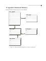
Appendix D (List of code segments)...................................................... 72
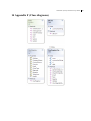
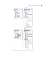
13
Appendix E (Relational Database)......................................................... 73
14
Appendix F (Class diagrams) ................................................................. 74
15
Appendix G (User Manual) ................................................................... 77
15.1
Web client ........................................................................................... 77
15.2
WRAP calculator .................................................................................. 85
15.3
Administrators ..................................................................................... 92
vii
Web-Based System for Radio Planning in WRAP
1 Introduction
Radio or Wireless communication is one of the emerging technologies that are advancing as
well as getting more challenging. Effectiveness and optimized solution for radio communication can be achieved with proper planning before deployment. Radio network planning is
designing of network structure and determining network elements subjected to various design requirements. With increasing radio frequencies shortage, radio planning jobs are getting tougher as well as deploying process of large radio networks is very expensive. Hence,
for achieving high resource utilization cautious planning is necessary. Moreover, maintaining high degree of accuracy and better optimization in manual designing and planning of
network is getting hard. This fact triggers the need of a computerized planning tool for future
and current networks. WRAP software is one example of such software that helps in planning networks.
In this thesis, a web-based system is developed which makes users able to plan a complex
radio network through his personal computer using an internet browser and connecting to
WRAP API server through internet.
1.1 Radio Communication and Spectrum management
Radio waves are radiated through free space by transmitting antenna and can be caught by
receiving antenna that is designed for the propagated frequency from the transmitting antenna. The process of emitting or receiving radio waves between two or more points is known
as radio communication. Increasing scope on it attracts many companies and researchers to
invest on developing automated tools to get accuracy and optimized solution.
Radio spectrum means range of frequencies of electromagnetic radiation within which radio
communication occurs. For example, “mobile telephones operate in a discrete portion of the
radio communications spectrum, generally below the 3-GHz range. The radio communication spectrum is a resource that is made up of radio communication waves that operate below
3000 GHz, though most of communication uses spectrum below 400 GHz” [12]. In coming
years, the number of users around the world will grow extensively leading to huge expansion
in demand for services using the radio frequency spectrum [1].
1.2 The WRAP software
WRAP software is a spectrum management and radio planning network software developed
by WRAP International AB, Linköping, Sweden. WRAP software includes various technical
calculations that are implemented to achieve design and analysis tasks with the purpose of
achieving the desired quality of service within radio communication networks, navigation
1
Web-Based System for Radio Planning in WRAP
and radar systems. Important tasks of the program are to calculate performance of microwave links and coverage areas for radio networks operators and radio planners both in Sweden and internationally.
1.3 Problem statement
From the current growth of radio frequency users, the demand in frequency spectrum gets
higher. To achieve efficient coverage and capacity with minimum cost and safety huge investment has to be made on building radio infrastructure. Automated radio planning tools
help user to plan optimized solution for building radio infrastructure.
Today many operating platforms and developments in the field of new technology are going
on. To adapt to the rapidly changing technological environment the tools for radio planning
and spectrum management also need to go mobile by adopting today‟s most promising internet technology.
The task comprises the research and development of system on internet and services for implementation of calculations in WRAP. Thus, enabling it to be handled by ordinary users and
being able to run it through browsers.
It is important that the user interface for the web applications is user friendly and simple to
use. Moreover, it should be appealing to users and customers that do not have experience
and technical proficiency in radio planning. Emphasis shall be placed on the logical and
intuitive properties for the user interface seen from a user‟s perspective and the provision of
an attractive, user-oriented result and report output.
WRAP system which has evolved through many years realized the need for the system to be
accessible to thousands of users in economical price and in various operating platforms. For
achieving the goal of WRAP the system is, should be built as a web based application using
latest mind set of RIA (Rich Internet Applications).
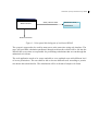
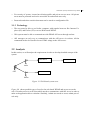
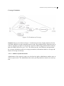
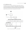
Conceptual block diagram of the functionality is shown in Figure 1-1. Through web interface authorized users could be able to perform calculations. WRAP has an API interface
which communicates in form of XML strings that defines instructions to be executed in
WRAP API server. Web interface must be able connect to the WRAP API server in order to
send/receive data (API messages), which are used to execute commands at remote API server as well as to gather result from remote server.
2
Web-Based System for Radio Planning in WRAP
Web interface
Send / Receive data
WRAP API server /
calculations
Authorized Users
Figure 1-1 Conceptual block diagram of web-based WRAP
The system is supposed to be used by many users at the same time using web interface. The
users will send their calculation parameters through web interface which will be fed into the
WRAP API servers that are responsible for performing calculations that are sent through the
authorized web clients.
The web application needs to be secure and able to serve multiple users with different level
of access permissions. The user shall be able to browse different tools according to permission he/she has subscribed for. The calculations will be in format of simple web forms.
3
Web-Based System for Radio Planning in WRAP
1.4 Thesis Organization
The thesis is organized as follows:
Chapter 2: (Background) this section provides an overview of the background materials
related to the thesis.
Chapter 3: (Requirement and Analysis) this section focuses on software engineering
process for web-based WRAP. This part defines requirements followed by its analysis.
Chapter 4: (Design and Implementation) this section put design according to requirement
and analysis presented in chapter 3. Moreover, Implementation of system will also be discussed.
Chapter 5: (System) This section shows how requirements, analysis, design and implementation were used all together to develop system.
Chapter 6: (Evaluation) This section shows how requirements were used to analyze the
results. This section also includes performance comparison between web-based and desktop
WRAP.
Chapter 7: (Conclusion) Conclusion of thesis and future possibilities.
References
Appendix A (List of abbreviations)
Appendix B (List of figures)
Appendix C (List of tables)
Appendix D (List of code segments)
Appendix E (Database Diagram)
Appendix F (Class Diagram)
Appendix G (User Manual)
4
Web-Based System for Radio Planning in WRAP
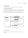
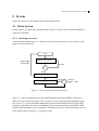
2 Background
This chapter discusses all background materials required to better understand the thesis.
2.1 Radio planning process
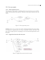
Planning of radio network is very challenging task. However, an organization can minimize
problems that may rise during deployment of network, with properly planned radio network.
The process of Radio network planning is shown in Figure 2-1. The network planning
process follows steps like requirement specification, dimensioning, planning and optimization.
Input
Process
Network Dimensioning
Requirements
(Site Estimation, configurations)
Coverage Related
Network Planning
Capacity Related
Quality Related
Coverage Planning and Site selection.
Coverage Prediction.
Coverage Optimization
Capacity Planning
Optimization
(QoS, enhancement, Network improvement)
Figure 2-1 Radio network planning process
2.1.1 Requirements
In requirement stage, operator‟s requirements on coverage, capacity and quality of service
are gathered.
5
Web-Based System for Radio Planning in WRAP
2.1.2 Dimensioning
Dimensioning phase must cover overall requirements provided by operator. The process
includes link budget calculation, coverage analysis and, finally, estimation on the amount of
base stations hardware and sites, equipments and core network elements [5].
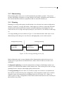
2.1.3 Planning
Planning of coverage and capacity should include; site selection, base station configuration,
analysis of capacity, coverage and quality. Link budgets are effective in showing the fundamental trends and principals before going in to detailed planning. Link budgets are associated with service coverage and capacity analysis. (See section 2.2 for details on Link budget)
Coverage planning process as shown in Figure 2-2 is divided into three main steps. It uses
dimensioning results that gives cost effective and high quality service radio network.
Coverage planning
Configuration planning
Link Budget
Calculation
Propagation
Measurements
Coverage Prediction
Figure 2-2 The coverage planning process [9].
Both configuration and coverage planning utilize dimensioning results and occurs in enclosed area or region known as calculation area, where effects of radio waves have to be
calculated.
Configuration planning or network configurations are based on link budget analysis (see
section 2.2) to minimize the number of base stations sites. This is done prior to the coverage
planning because it helps to obtain high quality radio network.
Coverage planning has to be done over certain coverage area so that we can optimize the
base station‟s location for the given configuration. The propagation of radio wave can have
obstacles on the environment such as buildings; hills etc (see section 2.2.1). Hence, to
achieve good coverage, configuration of base station and location must be chose carefully so
that obstacles may reduce.
6
Web-Based System for Radio Planning in WRAP
After coverage area and radio propagation environment have been analyzed and propagation
measurement1 is taken according to that prediction model is tuned. These tuning gives accuracy for coverage prediction.
2.1.4 Optimization
Network optimization is process to improve overall network quality to ensure network resources are used efficiently. For good coverage simultaneous optimization capacity and maximizing quality is needed.
Performance
analysis
Performance
measurement
Network
Tuning
Figure 2-3 Network Optimization process
Optimization process is shown in Figure 2-3 . Performance measurement data obtained by
network measurement device of current network are necessary to optimize performance.
Performance can be increased with better site and equipment configurations hence tuning up
site and equipment configuration helps for better performance. Performance analysis can be
done with the data provided at the performance measurement. These analyses are used to
tune network. The process is repeated until the satisfactory result is obtained.
2.2 Link budget
Link budget are one of the essential part in radio network design process. The designing
process consists of identifying the end points of the link where the transmitter (Tx) and re1
Propagation measurement is the process of analyzing areas to tune the radio propagation prediction model.
7
Web-Based System for Radio Planning in WRAP
ceiver (Rx) are located and examining the details of geographical environment (Details on
section 2.2.1). On the basis of this information parameters are assumed for a link configurations and finally, calculating the performance of this proposed design to determine if it meets
the required service and reliability objects. The basic calculation of link performance is
known as Link budget [4]. The link-budget is balance sheet of all gains and losses for the
link that is added to arrive at the mean signal level at the receiver. This can be used to evaluate availability of the link under a range of fading mechanisms.
Link power budget not only deals with the performance of radio hardware but also includes
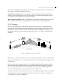
some features of environment. The Figure 2-4 depicts the scenario of radio service which is
used to calculate link budget.
The elements of design component of each radio communication system are the single wireless link that connects the transmitter (Tx) with the receiver (Rx).
Figure 2-4 Link budget parameters shown in diagram [24]
Even though Tx and Rx are placed into sufficient height to achieve maximum path clearance
there are several occurrence of losses which we will discuss on Transmission loss section
2.2.1
Simple Link budget equation is:
𝑷𝒓𝒙 = 𝑬𝑰𝑹𝑷 𝛗𝑹𝒙𝑻𝒙 + 𝑳𝒃 − 𝑮𝑹𝒙 𝛗𝑹𝒙𝑻𝒙 − 𝑳𝒇𝒊𝒍𝒕𝒆𝒓 − 𝑳𝒄𝒂𝒃𝒍𝒆 − 𝑳𝑿𝑷𝑫 − 𝑳𝒂𝒅𝒅𝒊𝒕𝒊𝒐𝒏𝒂𝒍
(2.4)
Where, 𝐸𝐼𝑅𝑃 φ𝑅𝑥𝑇𝑥 is the radiated power in direction toward the receiver, 𝐿𝑏 is the transmission loss, 𝐺𝑅𝑥 φ𝑅𝑥𝑇𝑥 is receiver main antenna gain in the direction toward the transmitter, 𝐿𝑓𝑖𝑙𝑡𝑒𝑟 is the loss at the transmitted frequency in the receiver filters, 𝐿𝑐𝑎𝑏𝑙𝑒 is loss of an-
8
Web-Based System for Radio Planning in WRAP
tenna cable, 𝐿𝑋𝑃𝐷 is the loss due to Polarization, 𝐿𝑎𝑑𝑑𝑖𝑡𝑖𝑜𝑛𝑎𝑙 is any extra loss in the receiver
side defined by user
For unwanted signals the link budget used is:
𝑃𝑟𝑥 = 𝐸𝐼𝑅𝑃 φ𝑅𝑥𝑇𝑥 + 𝐿𝑏 − 𝐺𝑅𝑥 φ𝑅𝑥𝑇𝑥 − 𝐿𝑠𝑝𝑒𝑐𝑡𝑟𝑢𝑚 − 𝐿𝑐𝑎𝑏𝑙𝑒 − 𝐿𝑋𝑃𝐷 − 𝐿𝑎𝑑𝑑𝑖𝑡𝑖𝑜𝑛𝑎𝑙
(2.5)
Where, 𝐿𝑠𝑝𝑒𝑐𝑡𝑟𝑢𝑚 is total loss where the full transmitter spectrum mask is filtered through
external transmitter filer, external receiver filter and the receiver selectivity [24].
2.2.1 Geographical Environment
To achieve a good link performance the link budget has to be achieved. The link budget
comprises the transmission loss which is affected by geography of propagation environment.
The main categories of geographical environment information that are used for calculating
the transmission loss are:
Terrains
Clutter
Atmospheric conditions
Terrains
Planning radio communication needs the knowledge of Terrain conditions. Terrains are the
vertical elevations of land surface such as hills, mountains, and other features, that can block
severely attenuate radio signals. Terrains can also reflect and scatter transmitted signals
creating multiple paths for them to arrive at the receiver. Topographic maps are the fundamental source of information of terrains. The map contains much information, including elevations.
Before invention of computer database that contain terrain information generating topographic map is very difficult, error-prone manual process which are used for many years.
However, with invention of computer database, traditional paper based topographical map
are replaced with digital map. Since then digital map is one of the basic components of the
modern radio planning because of its capacity to hold information in map.
9
Web-Based System for Radio Planning in WRAP
Figure 2-5 Topographic map [21]
Digital map can be presented either in raster or vector format. Typically raster data are topographic and morphographic data as well as it can include other data layers such as building
heights, traffic density etc. Data such as roads, borders, railways and texts are usually in vector format.
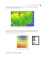
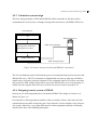
Terrain information is presented in raster format in some planning systems. Each pixel has
its own terrain height information as shown in
Figure 2-6. The value is calculated based on the height model. If resolution 2 of map is not
good there can be errors in terrain height model.
54
52
51
56
50
51
55
50
53
52
54
51
53
52
53
50
Figure 2-6 Raster topographic data (terrain height varies between 50-56 m)
Clutter
The land cover and land use information that classify its character at the particular location
on the earth can be found in Clutter database. Classification such as urban areas, forest, wa2
“Resolution is the smallest unit on the map that can be presented; they are presented on pixel size”.
10
Web-Based System for Radio Planning in WRAP
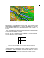
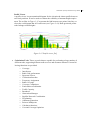
ter and agriculture land are typically found. Figure 2-7 is Land coverage map of Östergotland, Sweden generated in WRAP software.
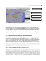
Figure 2-7 Land coverage map of Östergotland, Sweden
As shown in Figure 2-7 which is a raster image, where each pixel has only one value that
defines property of the pixel. In the morphographic layer different land-usage classes are
presented as different terrain-type class see Figure 2-8.
Urban
Water
Forest
Figure 2-8 Raster morphographic data
Atmospheric and meteorological conditions
11
Web-Based System for Radio Planning in WRAP
The effects of changing meteorological and atmospheric condition affect the communication
performances in radio communication system.
Atmospheric conditions such as rain and snow all have significant effects on the link performance. Rain attenuation below 10 GHz frequencies are considered insignificant. However, frequencies above that limit have significant effect.
Meteorological conditions such as the databases that define the conditions that occur in the
land area where radio links is being deployed are necessary for accuracy in planning.
2.2.2 Clearance
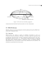
To obtain maximum gain in Link budget, transmission system must be planned perfectly.
Transmission system planning includes identifying the location and height of those Tx and
Rx, which are chosen in such a way that the obstacles such as buildings, mountains etc between them must be clear from blocking signals (See Figure 2-9.). This is called link path
clearance.
Rx
Tx
Rx
Tx
Mountains
TxRx Stations
TxRx Station
Lakes
Buildings
Tx Station
Earth Surface
Rx Station
Figure 2-9 Radio communication Link
The objective of network design is to obtain maximum path clearance. However, path cannot
continue in straight line due to refractivity of atmosphere. Such diffracted path lengths create
Fresnel zones.
Fresnel zone in radio communication is “one of the theoretically infinite concentric ellipsoids of revolution which define volumes in the radiation pattern of a (usually) circular aperture.” [6]. The cross-sectional view of first Fresnel zone is circular and following Fresnel
zones are ring-shaped in cross section, and concentric with the first.
As shown in Figure 2-10 below the Fresnel zone form elliptically shaped solid of revolution
around transmitter-receiver propagation path. Where, distances d1 and d2 are in kilometers,
n is ellipsoid,r1 is radius of ellipsoid n1.
12
Web-Based System for Radio Planning in WRAP
n3
n2
n1
d2
d1
r1
Transmitter
Receiver
Propagation path (can be curve)
Figure 2-10 Fresnel zone around the propagation
At least 60 percent of the first Fresnel zone needs to be clear of obstructions.
2.3 WRAP Software
WRAP is software for spectrum management and radio planning developed by WRAP International AB, Linköping, Sweden.
2.3.1 Overview
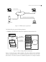
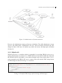
WRAP software has capacity to operate in standalone environment as well as in
Client/Server network environment. This makes it accessible as multi-user application from
geographically separated locations. The basic organization of WRAP software with centralized database is shown in Figure 2-11. Clients located in different locations are connecting
and sharing single centralized database or alternatively replica of centralized database.
WRAP database server is the collection of all necessary information for the calculation. The
calculations are performed in the client system.
13
Web-Based System for Radio Planning in WRAP
Fixed connection
Client System
Client System
Fixed connection
Network
Alternative connection using db Replica
Fixed connection
WRAP database
server
Client System
Figure 2-11 WRAP software organization
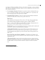
The WRAP defines the system in following functions:
Databases: WRAP Database mainly stores equipments, stations and users list.
Project.wpr
Save/Open
Stations
Stations
Transmitters
Transmitters
Receivers
Antenns
Cable
Filters
Installation
independent
Receivers
Antennas
Cable
WRAP db
Filters
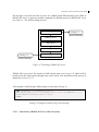
Figure 2-12 Basic working of WRAP with database
Figure 2-12 shows the types of data in database. The data in database can be installation
dependent and independent data. The installation dependent data means the data at the installation radio site. The data for stations are installation dependent as for example coordinates
14
Web-Based System for Radio Planning in WRAP
can change in different installations. However, the data for transmitter, receivers, antennas,
cable, filters are installation independent which can also be changed but it will affect all stations using that equipments.
User workspaces (Projects): Workspaces or projects are basic working block for any
types of calculations in WRAP. The projects files in WRAP are in *.wpr format. The
user can open project file with valid version of WRAP.
Presentation Tools (Viewers): Viewers are used to present and analysis results and
problems. Normally there are map viewers, profile viewers etc.
Map Viewers
Map in WRAP can be displayed in 2D as well as in 3D. Map with geographical data
used in WRAP. Many geographical settings for map are available in WRAP.
Figure 2-13 below shows different map that WRAP can display, with projection of selected geoclass3 that are global settings for all opened project.
National grid is a system of geographic grid references commonly used in nations such
as Sweden etc, different from using latitude and longitude.
“Orthographic Projection is map projection that presents the Earth's surface in twodimensions as if it were being observed from a great distance in space. Distortion of
areas and angles becomes greater as you move from the center of the projection to its
edges” [19].
Great circle (True centre distance azimuthal): “An imaginary circle drawn on the
Earth's surface that has its center synchronizes to the center of the planet. The equator is
a great circle” [19].
“Mercator projection is map projection system that presents true compass direction.
Distortion is manifested in terms of area. Area distortion makes continents in the middle
and high latitudes seem larger than they should be designed for nautical navigation”
[19].
3
Geo Class (Geographical database sets)
15
Web-Based System for Radio Planning in WRAP
Figure 2-13 2D map viewers in different projections [24]
3D map in WRAP uses exaggerated height scale, which improves the presentation for the
instance results based on propagation models using diffraction.
Figure 2-14 3D map viewer [24]
16
Web-Based System for Radio Planning in WRAP
Profile Viewer
A profile viewer is representational diagram for the elevation & clutter profile between
two fixed positions. It can be used to evaluate the reliability of antenna height requirement. The red line in Figure 2-15 represents the link between two points; blue line encloses the oval diagram that is Fresnel zone (see Figure 2-10). Dark green and yellow
color belongs to land heights.
Figure 2-15 Profile viewer [24]
Calculation Tools: Those are tools that are capable for performing a large number of
different tasks, supporting different radio services and customer demand. Current following functions are provided:
o
o
o
o
o
o
o
o
o
o
o
o
o
o
o
o
o
o
Coverage
Interference
Radio Link performance
Spectrum Viewer
Collocation Interface
Frequency Assignment
Radar Coverage
Coverage Comparison
Earth station coordination
Traffic Capacity
Broadcast
Obstruction Manager
Satellite Network Coordination
HF planning
Allotment generation
Point-to-Multipoint
Calculator functions
Cost and Coverage Optimizer
17
Web-Based System for Radio Planning in WRAP
Out of much functionality in WRAP for this thesis we will focus on part of coverage calculations and necessary facilities to perform Coverage calculation and reporting.
Administrative Tools: These tools are used for administration of different function
such as network management, spectrum allocation manager etc. in WRAP.
Map Data Manager: it is stand alone application that is used to create or update Geographical database used by WRAP.
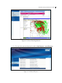
2.3.2 Coverage Calculations in WRAP
Coverage calculation is one of the commonly used tools in WRAP which will be implemented and analyzed for this thesis purpose. In WRAP to calculate coverage user have to
define one or more stations and need to define how actual calculation shall be performed.
All other necessary technical parameters are retrieved from the WRAP database.
Coverage areas are formed based on transmission loss calculations for each transmitter of
interest. The received wanted signal level is calculated by accounting of transmitter power,
transmitter antenna azimuth diagram, receiver antenna gain, receiver antenna azimuth diagram, filter loss and cable losses.
For interfering signals the calculation in addition accounts for the transmitter spectrum mask,
transmitter and receiver antenna filters and the receiver selectivity. Change of any station or
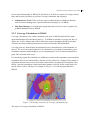
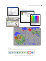
equipment characteristics can easily be done which will be recognized by subsequent calculations. After the calculation is done an arbitrary number of levels for the result can be displayed either in 2D or 3D map. For example in Figure 2-16 is 2D map presentation in
WRAP.
Figure 2-16 2D map with result of coverage calculation [24]
The steps of Coverage calculation in WRAP:
18
Web-Based System for Radio Planning in WRAP
o Choose option whether to perform normal calculation in one of common map for all
stations or marked stations only, OR in user-defined circle around each station.
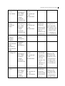
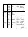
o The number of different calculation shown in Table 2.1
o Probability of coverage or the coverage for a given probability can be calculated.
o Choose Uplink or Downlink calculation where applicable.
o Use definable mobile, select height reference for the mobile as above sea level (ASL)
or above ground Level (AGL) or Above ground level and buildings.
o Define calculation area; it can be polygon, circle, line and point. These are can be defined in the Map viewer or import area from text file.
o Point calculation can be set form stations in the station list.
o Define calculation resolution as defined in Table 2.2
o Calculation of percentage coverage of terrain classes of selectable types
o Post processing of individual coverage result to combine them into composite coverage, best server or number of server results
o Can store coverage results that are uniquely connected to single station in wrapdb
and can be retrieved automatically when making add to project operation in the station in database.
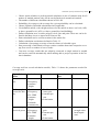
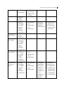
Coverage tool has several calculation models; Table 2.1 shows the parameters needed for
coverage tools.
Type of calculation
Transmission
loss
Station data
Position
Frequency
Antenna
height
Field strength, Position
Power flux den- Frequency
sity
Tx: EIRP
Antenna
height
Azimuth
Antenna tilt
Signal strength, Position
Received power Frequency
Tx: EIRP
Antenna
height
Antenna data
Transmitter
data
-
Receiver data
Tx: Max antenna gain
Antenna pattern
Polarization
-
-
Max antenna
gain
Antenna pattern
Polarization
-
If signal
strength calculated impedance.
Polarization
-
19
Web-Based System for Radio Planning in WRAP
Azimuth
Antenna tilt
Clearance
S/I
Required Antenna Height
Terrain Clearance Angle
Best server,
noise limited
Best server interference limited
Antenna
height
Frequency
Position
Frequency
Tx: EIRP
Antenna
height
Azimuth
Antenna tilt
Antenna
height
Frequency
Position
Frequency
Tx: EIRP
Antenna
height
Azimuth
Antenna tilt
Position
Frequency
Tx: EIRP
Antenna
height
Azimuth
Antenna tilt
Position
Frequency
Tx: EIRP
Antenna
height
Azimuth
Antenna tilt
Mobile: Max
antenna gain
Mobile: Polarization
Max antenna
gain
Antenna pattern
Polarization
Occupied
bandwidth
frequency
characteristics
Sensitivity Required S/I
IF-bandwidth
frequency characteristics
-
-
-
-
-
-
Max antenna
gain
Antenna pattern
Polarization
-
Sensitivity
Max antenna
gain
Antenna pattern
Polarization
Occupied
bandwidth
Frequency
characteristics (not
needed if only cochannels to
be considered)
Sensitivity
Required S/I
IF-bandwidth
Frequency characteristics(not
needed if only
co-channels to
be considered)
20
Web-Based System for Radio Planning in WRAP
Number of
servers,
Noise limited
Number of
servers,
Interference
limited
Position
Frequency
Tx: EIRP
Antenna
height
Azimuth
Antenna tilt
Position
Frequency
Tx: EIRP
Antenna
height
Azimuth
Antenna tilt
Max antenna
gain
Antenna pattern
Polarization
-
Max antenna
gain
Antenna pattern
Polarization
Occupied
bandwidth
Frequency
characteristics
(not needed if
only cochannels to be
considered)
Sensitivity
Sensitivity
Required S/I
IF-bandwidth
Frequency characteristics (not
needed if only
co-channels to
be considered)
Maximum
Clearance
Minimum
Clearance
Maximum Required antenna
height
Minimum required antenna
height.
Composite
Coverage, S/I
Antenna
height
Frequency
-
-
-
Antenna
height
Frequency
-
-
-
Position
Frequency
Tx: EIRP
Antenna
height
Azimuth
Antenna tilt
Max antenna
gain
Antenna pattern
Polarization
Sensitivity
Required S/I
IF-bandwidth
Frequency characteristics(not
needed if only
co-channels to
be considered)
Number of interferers
Max antenna
gain
Antenna pattern
Polarization
Occupied
bandwidth
Frequency
characteristics (not
needed if only cochannels to
be considered)
Occupied
bandwidth
Frequency
characteristics
(not needed if
only co-
Position
Frequency
Tx: EIRP
Antenna
height
Azimuth
Sensitivity
Required S/I
IF-bandwidth
Frequency characteristics(not
needed if only
21
Web-Based System for Radio Planning in WRAP
Antenna tilt
Worst interferer
Neighbor cell
noise limited
Neighbor cells,
interference
limited
Position
Frequency
Tx: EIRP
Antenna
height
Azimuth
Antenna tilt
Max antenna
gain
Antenna pattern
Polarization
Max antenna
gain.
Antenna pattern.
Polarization
Adjacent cell
Coverage, S/I
Position
Frequency
Tx: EIRP
Antenna
height
Azimuth
Antenna tilt
Position
Frequency
Tx: EIRP
Antenna
height
Azimuth
Antenna tilt
Position
Frequency
Tx: EIRP
Antenna
height
Azimuth
Antenna tilt
channels to be
considered)
Occupied
bandwidth
Frequency
characteristics
(not needed if
only cochannels to be
considered)
-
Max antenna
gain
Antenna pattern
Polarization
Occupied
bandwidth
Frequency
characteristics
(not needed if
only cochannels to be
considered)
Max antenna
gain
Antenna pattern
Polarization
Occupied
bandwidth
Frequency
characteristics
co-channels to
be considered)
Sensitivity
Required S/I
IF-bandwidth
Frequency characteristics(not
needed if only
co-channels to
be considered)
Sensitivity
Sensitivity
Required S/I
IF-bandwidth
Frequency characteristics(not
needed if only
co-channels to
be considered)
Sensitivity
Required S/I
IF-bandwidth
Frequency characteristics(not
needed if only
co-channels to
be considered)
Table 2.1 Coverage calculation models and parameters [24]
22
Web-Based System for Radio Planning in WRAP
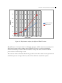
There are different calculation resolutions used in WRAP which is defined in table below:
Label
Description
Very Low
625 area calculation points or 25 line calculation points. For very rough
estimates or calculations involving an extremely large number of
transmitters in a smaller area.
Low
2 500 area calculation points or 50 line calculation points. For rough
estimates.
Average
10 000 area calculation points or 100 line calculation points. Default
setting which is adequate for most purposes-
High
40 000 area calculation points or 200 line calculation points.
Very High
160 000 area calculation points or 400 line calculation points
User Defined
The resolution given in meters can be entered by users, same resolution
is used in both direction
Table 2.2 Resolutions used in WRAP [24]
2.3.3 WRAP API Server
WRAP API is part of the WRAP software system. The basic system contains project.exe and
some DLL-files which contain basic functionality within spectrum management. Special
tools of greater dignity can be added to WRAP as DLL-files, e.g. RadarCoverage.dll. The
use of a DLL-structure allows several different software engineers to work continuously with
different DLL-files.
Connection with WRAP API is done via sockets with definite port number. The port in
WRAP API server is configured using “APIConfigFile.txt” file. Similarly, timeout for the
socket can also be configured in similar file. Users can change the port number and timeout
as per their requirements. However, changing the port while WRAP server is running is not
allowed. API server uses XSD files to verify incoming XML strings, the valid XML are
parsed which will gives the input to the WRAP server. If the XML string is invalid it will
generate error message. The WRAP server will process the data submitted parsed XML as
input command values. The WRAP calculation will generate result in XML string format.
23
Web-Based System for Radio Planning in WRAP
2.4 Software Framework
A software framework provides powerful tools to develop flexible and less error prone software applications in a more efficient way. It often helps speed up the development process
by providing necessary functionality. That includes user/role management, data access, caching and others.
Framework help on focusing on more important details of design and project management
by justifying the need to reuse for common development needs. For web there are both server-side and client side framework.
There are several popular frameworks for server side languages like CakePHP for PHP,
spring for JAVA, .NET for C# etc. For client side, the framework like jQuery, Prototype,
ASP.NET AjaxToolkit for JavaScript, blueprint for CSS and OpenLayers.
Openlayers is JavaScript library for displaying map in web browsers. It is built for rich webbased geographic applications. OpenLayers is free and developed by Open Source 4 Software
community [17].
2.5 Internet and sockets
Internet is global system of interconnection between computer networks using standard internet protocol suit (TCP/IP). It serves billions of users worldwide.
Sockets are interface between application process and transport layer. Application process
can send/receive message from another application process and vice versa through sockets.
There are many types of socket such as Internet Sockets, Unix Sockets, X.25 sockets etc.
Internet Sockets are characterized by IP address (4 bytes), port number (2 bytes).
2.6 Web-based system
Today millions of people around world using internet in order to share information make
new relations and communicate. From individuals, to professionals, to developers all are
benefited from to power of internet. Rather than using the internet in limited areas such as
communication and file sharing, it is used for developing complex applications featuring
responsive user interfaces and highly interactive capabilities. These types of application are
called as web applications. A technology such as RIA makes web systems more powerful.
2.6.1 Rich Internet Application (RIA)
Rich Internet Application (RIA) encourages developing browser based application. Rich
Internet Application (RIA) combines elements of rich user interactivity and client-side logic
once solely the domain of desktop and client/server applications with the distributed compu4
Open source software is computer software for which source, permission to use, change and improve the
software and to redistribute it in modified or unmodified forms is provided to all users.
24
Web-Based System for Radio Planning in WRAP
ting power of the Internet [23]. Various web tools such as Adobe Flash/Flex, Microsoft Silverlight, and AJAX etc can be used to build RIA. We will be discussing about few technologies below.
2.6.1.1 Technologies for RIA
Many platforms can be used to develop RIA. However, certain platforms have gain popularity on developing the product providing features that proves helpful on development of RIA.
AJAX (Asynchronous JavaScript And XML)
AJAX has changed many aspect of web application development (see Figure 2-17). Before
AJAX, web was used to share static pages of information. Over years it evolved into more
dynamic medium. Today, at the heart of new technology lays a single page interface model
that facilitates rich interactivity. With AJAX features, web changes are made to individual
user interface components contained in a web page, as opposed to refreshing the entire page.
AJAX architecture
Figure 2-17, which shows architectural difference between traditional Web approach and
AJAX based web approach. In traditional Web application everything is processed at the
web server except few scripts that run at the client‟s end such as data validation. In contrast,
AJAX based application uses client-side logic that handles issues calls to the Web server. At
end of server AJAX server-side takes care of request and returns data feeds to the client.
The client receives data feeds from server which are used to update UI using javaScript.
Bandwidth consumption are comparatively low in AJAX based systems as well as the speed
of application were improved.
25
Web-Based System for Radio Planning in WRAP
HTTP Request
Browser
Client page
HTML markup for new page
Web-Server
Web application
Classic WEB
HTTP Request
Browser
Web-Server
HTML markup for new page
AJAX Library
AJAX Library
Client page
Asynchronous Request
Web application
Asynchronous Response
AJAX
Figure 2-17 Classic vs. AJAX Web Model [16]
Adobe Flash/ Flex, Flex is an open source platform for creating rich internet applications.
Application built with Flex can be deployed using Flash plug-in. It provides standards-based
languages and programming model that supports common design pattern. It uses MXML a
declarative XML-based language, used for development of UI and uses ActionScript to
create client logic.
Adobe Flash is multimedia platform distributed by Adobe system. It was introduced in 1996.
Flash provides websites with interactivity, animation and to develop RIA. It can manipulate
both vector and raster graphics and supports bidirectional streaming of audio and video. For
scripting flash uses ActionScript. The feature that adds flash with more powerful is socket
programming.
Microsoft Silverlight, Silverlight is a runtime browser plug-in which need to be installed in
browser in order to start web applications with Silverlight. Silverlight combines multiple
technologies in to single platform and allow us to select comfortable tool to develop system.
Like in flex, Silverlight also use XAML as a declarative XML based language for building
UI and uses various languages like C#, VB, JavaScript etc for client logic.
2.6.1.2 Comparison between RIA technologies
There are many technologies that can be used to build RIA; out of this we had discussed
some in section 2.6.1.1. There are many advantages and disadvantages involved while implementing those tools, in this section we will try to discuss some of them.
26
Web-Based System for Radio Planning in WRAP
RIA technology like Ajax does not have high interactivity compared to Flash and Silverlight.
For example, in Ajax RIA it is difficult to integrate interactive media and video streaming
than Flash and Silverlight.
The Flash and Silverlight both are rich in multimedia and interaction, Silverlight has capacity to use rich sets of language for coding where as flash only uses ActionScript. In addition
Silverlight is supported by ranges of services provided by Microsoft. On the other hand,
flash can perform well equally in windows, Linux and Mac systems, where as Silverlight
need separate plug-in called moonlight to run on Linux.
There are many technologies involved in web-based application that makes it user-friendly
interfaces for web application is possible. Web2.0 is one of the examples of richness of webbased system.
2.6.2 Web 2.0
Web 2.0 is a combination of various technologies. These technologies have given new momentum to next generation applications. The technologies that are part of web 2.0 can categorized as in Figure 2-18.
Clients
(Browsers, PDA or Mobile)
Ajax
Internet
Application Environment
Http/HTTPS
Infrastructure
JSON, JS-objects, XML
& custom (structures)
Web Server
Application Server
Flash
Silverlight
XML-RPC, REST,
SOAP (Protocols)
Web Services (SOA)
HTML
database
Other Domain Apps
Third-Party environment
Figure 2-18 web 2.0 higher-level architecture [23]
Client-side technologies in web 2.0 have facilitated clients in many ways. Web 2.0 has given developers components such as Ajax which make application possible to invoke these
27
Web-Based System for Radio Planning in WRAP
components using JavaScript. This makes client application very attractive. Similarly flash
based application builds RIA that provides a real desktop-type feeling in the browser itself.
Web 2.0 application uses several protocols over HTTP or HTTPS. XML information packages act as channels between clients and applications or between applications over the internet.
Protocols such as SOAP5, XML-RPC6, and REST7 are emerging technology for next generation applications. Web 2.0 applications need to communicate with backend or third party
web services and to do so it needs XML envelops running over traditional HTTP/HTTPS.
Browsers are powered to access their domain applications using different calls.
GET/POST HTTP methods are used for exchange simple “querystrings” between browser
and server in Web 1.0. Introduction to Ajax with other technologies such as XML, JSON,
JS-array, RSS are used in Web2.0 to exchange several information structures. All of these
structures can be consumed by using scripting languages in browser [23].
Web 2.0 application environment has changed dramatically to incorporate this new architecture. SOA is one of the key elements that provide various set of web services that can be
consumed by the target browser.
2.6.3 Web 3.0
“Web 3.0 is defined as the creation of high-quality content and services produced by gifted
individuals using Web 2.0 technology as an enabling platform.” [calacanis.com]
According to Tim Berners-Lee, inventor of the World Wide Web has said Web 3.0 technologies “will become capable of analyzing all the data on the Web – the content, links, and
transactions between people and computers. A „Semantic Web,‟ which should make this
possible, has yet to emerge, but when it does, the day-to-day mechanisms of trade, bureaucracy and our daily lives will be handled by machines talking to machines”[2].
2.6.4 Web servers
Every web pages or systems, either web applications are made with web 2.0 standards or
web 3.0 standards they needs some place to store it, which then can make it available for rest
of the world. Such a storage which serves these pages is known as web servers. Every web
server has an IP address and most probably domain name as well.
For a computer to work as a web server it should have server software installed and configured on it. There are many web server software such as Apache, IIS etc.
5
“ SOAP is a simple XML-based protocol to let applications exchange information over HTTP”[
http://www.w3schools.com/soap/default.asp]
6
“ It's remote procedure calling using HTTP as the transport and XML as the encoding”
[http://www.xmlrpc.com/]
7
“It describe an architecture style of networked systems” [http://www.xfront.com/REST-Web-Services.html]
28
Web-Based System for Radio Planning in WRAP
Apache web server software is open-source HTTP server, this plays vital role for making
World Wide Web (WWW) popular. It supports various features and implemented many
modules to increase the functionality. It supports server-side programming languages like
PHP, Python, Tcl and Perl.
IIS (Internet Information Services) is also web server software, created by Microsoft for
use with Microsoft windows. It supports server-side programming language like ASP,
ASP.NET, and PHP etc.
Security in IIS, for older versions of IIS there are many issues related to vulnerability. For
example, the vulnerability problem such as defined on CA-2001-138 gives buffer overflow9
in indexing service DLL, which gives attacker control of the web server. As a result of vulnerabilities in IIS, Microsoft has completely redesigned IIS in order to make it secure. [22].
8
[http://www.cert.org/advisories/CA-2001-13.html]
9
Buffer overflow occurs when a process tries to store data on buffer more than its actual capacity. Buffer over-
flow is one of the important issues in software security.
29
Web-Based System for Radio Planning in WRAP
30
Web-Based System for Radio Planning in WRAP
3 Requirement and Analysis
In this chapter we will discuss requirements for the project, and analyze the feasibility of
important parts of WRAP that we are going to implement.
3.1 Requirements:
In this section we will discuss about the required features that have to be available in web
version of WRAP. The requirements are given by WRAP International AB, are listed in details below:
3.1.1 User interface (UI)
o User interface must be simple and user-friendly, so that users with very basic internet
browsing knowledge can operate the solution.
o All the calculation tools and interface for calculator must be available in single page so
that:
User can provide all required inputs at different stages of calculation.
User can observe instant results on queries, which he can compare with his input.
User can have better interaction with respective services at WRAP API server.
o UI of calculator must have map browsing and could be able to display map from WRAP
API server.
o Output or results of calculation must also be visible in similar page.
3.1.2 Functionality
o A new user can register to the system; can buy access to web-based WRAP system using
online payment.
o Web-based WRAP must contain separate management pages for users, administrators
and calculations. The access to calculation panel must be given for valid users only.
o User must be able to open and save their respective project files. And must be able to
open them anytime, from remote locations using web-based WRAP
o An administrator of system can add and alter user permissions, System parameters as
well as other managerial issues.
o Web-based WRAP at the initial phase does not require covering all functionality. However; it should be open for extensions.
31
Web-Based System for Radio Planning in WRAP
o For security of system, it must have distinct public and private access areas. All private
areas must be protected and can be accessible for authorized users only.
o Passwords and other sensitive data must not be stored on configuration file.
3.1.3 Technology
o The user must be able to use his/her computer with popular browsers like Internet Explorer (IE) and Firefox (FF) to access Web-based WRAP.
o Web system must be able to communicate with WRAP API server through sockets.
o API messages are only way to communicate with the API server via sockets. All the
commands need to be issued in form of XML strings to the API servers.
3.2 Analysis
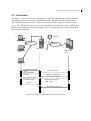
In this section, we will analyze the requirements in order to develop detailed concept of the
system.
Web Client
API server
Client
User
Web Admin
Admin
Figure 3-1 Web-Based system users
Figure 3-1 shows possible types of user for the web-based WRAP and access are on the
web. Client has access to web client which needs to communicate with API server in order to
make web application able to calculate. Similarly, Admin user needs to access admin part of
web only.
32
Web-Based System for Radio Planning in WRAP
3.2.1 Use case scenario
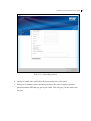
3.2.1.1 Client registration process
The main purpose of this project is establishing effective interaction between users and Websystem. The users/clients of the system are valid users of the system, which can access the
system.
Figure 3-2 Client registration process
Scenario: If user is new or if user does not have valid login parameters they must register.
On completion of registration the user will get confirmation in his/her email inbox. That
gives access to sign up process. On signing up, user can create desired password to access
the system.
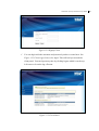
3.2.1.2 Logged client interaction with web system
Figure 3-3 logged Client interaction with web system
33
Web-Based System for Radio Planning in WRAP
Scenario: A logged user can access client panel and that gives user access to change password, write/view notes or logs, view help topics, and perform allowed calculations. The user
may logout anytime.
3.2.1.3 Calculation
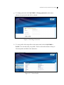
Calculation module is major part of the thesis. A user of the system needs good and clear
user interface for calculation. Out of many calculation tools in WRAP for web-based system,
part of coverage calculation is analyzed and designed. However, to make system full functional, we need to implement various tools such as map browsing tools, scale tool and other
conversion tool etc.
Map Interaction
Scenario: User can use map for many purposes, he/she can get coordinate positions on the
map, add markers, add new stations, can view map in different scales, and change map settings. When user changes map settings, which means user might want to see different kinds
of map such as relief map, landcover map, map with various vectors or image data etc. After
setting all required input parameters for the coverage calculation user can send command for
calculation to the system. And it must interpreted them into respective XML strings and send
to WRAP API server as command which will return back result parameters after server
completed processing.
Figure 3-4 Map Interaction
34
Web-Based System for Radio Planning in WRAP
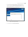
Coverage Calculation
Figure 3-5 Calculation of Coverage
Scenario: The use case shown in Figure 3-5 shows the necessary design parameters for the
web-based WRAP coverage calculation and its result. The command issues from the users in
order to calculate coverage are converted to respective XML strings which will be treated as
input for WRAP API server (see 3.2.2). The client can also view different result generated
by coverage calculations such as coverage presentation, information related to coverage and
layout of coverage on the map.
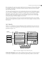
3.2.1.4 Admin to System interaction
Administrator of the system is super user who has the right to administrate another users as
well as system tools. The administrator has some special permission control users and system.
35
Web-Based System for Radio Planning in WRAP
Figure 3-6 Administrator to System interaction
However, the administrator cannot perform any calculation. The valid administrator can get
access to the admin panel. Administrator can view, edit user details and he/she may also
change the data of the users. In similar way, she/he can create, edit help topics, broadcast
message etc.
3.2.2 WRAP-API
WRAP API server is a machine which is responsible for providing WRAP services to response API message (see section 2.3.3). WRAP API servers are able to handle the entire task
that WRAP software can handle. It can connect through socket from remote places. For issuing command to the WRAP API server a remote client will send the XML strings known
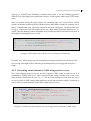
as API messages as shown in Listing 3:1 via sockets.
<?xml version="1.0" encoding="utf-8" ?>
<WRAP xmlns="WRAP:API:1.0" wrapXMLVer="0.1" reference="Kalle Anka"
visible="true">
<Project reference="Musse Pigg">
<New/>
</Project>
</WRAP>
Listing 3:1 Example XML strings request message (API messages)
36
Web-Based System for Radio Planning in WRAP
The message received from client to server are validated with XSD and then parse XML in
WRAP API server to generate sensible commands for WRAP process in WRAP API server
(see Figure 3-7 for detail working process).
XML string as results
Listing 3:2
Response Message
WRAP process
XML parser
XSD (Validator)
Socket connectors
Listing 3:1
Request Message
WRAP API server
Figure 3-7 Working of WRAP API server
WRAP API server gives the results in XML sting format (see Listing 3:2) which will be
transferred to the client system through same active socket. The interaction of this process is
analyzed in section 3.2.2.1
The example of API message XML strings is as shown in Listing 3:1
<?xml version="1.0" encoding="utf-8" ?>
<WRAP xmlns="WRAP:API:1.0" reference="Kalle Anka" wrapXMLVer="0.1">
<ProjectResult reference="Musse Pigg"/>
</WRAP>
Listing 3:2 Example of XML string result message
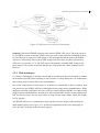
3.2.2.1 Interaction of WRAP API server with web system
37
Web-Based System for Radio Planning in WRAP
Figure 3-8 API servers to web server interaction
Scenario: Web-based WRAP connects to the remote WRAP API server. The web system is
UI for WRAP system on internet. While client uses web system tools the command needs to
be converting in to respective XML stings or API message that will be sent to the WRAP
API server via sockets. On arrival of XML string from web-client, it will be processed by
API server (see section 2.3.3). The API server with generate resulting XML string for the
given request. The results are parsed and data are converted to the visual elements in web
browser.
3.2.3 Web techniques
It is always challenging to develop system that is operating on one environment to another
environment especially from desktop to web, because of many differences in architectures
and working styles between these two environments.
One of the requirements of this project is to build web system that is able to connect from
web browser to the WRAP API server through network using socket communication. While
analyzing available techniques for web, a browser which supports HTML 4.x cannot really
support socket communication. In order to be able to participate in active socket communication for browser there are few ways such as using sockets from Adobe Flash, Silverlight,
JAVA Applets.
The WRAP API sever is constructed in such way that it need a unique socket session for
entire unique project (see Figure 3-9). So browser application needs to be single page to
solve the issue of unique socket for entire project.
38
Web-Based System for Radio Planning in WRAP
Browser 1
Socket 1
Socket 1
Project 1
Browser 2
Socket 2
Socket 2
Project 2
Browser n
Socket n
Socket n
Project n
Figure 3-9 Browser to WRAP API server communication
There can be number of browsers. Each browser can connect to server with its own unique
sockets, the accepted socket will open a project at server and entire calculations are made on
that socket. Various techniques can be used for that purpose such as using AJAX, JavaScript
frameworks like jQuery, building over all system in FLASH or using Silverlight.
Other web platform like .NET framework enable to use facilities of Microsoft libraries and
in same time can take full advantage of Ajax and other JavaScript functions.
3.2.4 Security
Along with rising popularity of web based applications, number and sophistication of attacks
against these applications have also grown. To secure web applications focus either on detection and blocking attacks using firewalls or using vulnerability analysis techniques to identify security problems is required.
There are numbers of factors on web that makes analysis of security complex such as use of
scripting languages, interaction with back-end database. The security for web-based WRAP
system can be divided in parts to assure, we are checking each possible option to make system secure right from the design process. However, making system free from all vulnerabilities is very hard to achieve.
For security in web-based WRAP, user needs to be classified as per their access permissions
such as public and private users. Public users can visit all public parts of system where as
private user will have identity for entering the system. Passwords which are needed to verify
the access will be validate at the web server. All the necessary security related validation will
be carried out on the server rather than client side.
Sessions will also help to maintain you identification while browsing the web system. Sessions can help to increase security in web based application by identifying activity of valid
users at different parts of the web application.
39
Web-Based System for Radio Planning in WRAP
40
Web-Based System for Radio Planning in WRAP
4 Design and Implementation
In this section we will discuss how system is designed and Implemented according to design
to fulfill requirement of the system.
4.1 System Architecture
The architecture of the Web-based WRAP is as shown in Figure 4-1. Web clients are normal
internet users who uses browser and have access to Web-based WRAP system.
Internet
Web Server
Virtual Link
WRAP API Server
Browser
User
Figure 4-1 Architecture of Web-based WRAP web client
All valid users must have their own login key which gives them access to the system. The
users can explore his personal section with access to permitted calculations performed in
WRAP API server.
When user tries to access calculation, the web interfaces of WRAP are connected to the
WRAP API server via sockets using DNS. The system will provide user access to calculation without understanding the complex techniques behind connection between web server
and WRAP API server. That means, for valid users, a virtual link between wrap API server
and user‟s browser has been established.
4.2 Software Design
41
Web-Based System for Radio Planning in WRAP
In design part, we will analyze how different part of system will work in order to get perfections in system as per the requirements.
User
Login
If Client
If Administrator
?
Client Panel
Administrator Panel
Personal settings
User Administration
Calculations
Settings & reports
Figure 4-2 Web-Based WRAP Users
There are basically two types of users in web-based WRAP such as administrative users and
WRAP clients. All users need to login in order to get access on the system. However, there
are respective control panels for different kinds of users. A control panel is control page with
tools and configurations that can be used to configure settings and access tools that are required.
4.2.1 Client system in Web-based WRAP
Web-based WRAP system has two types of users as discussed in section 4.2. Client of the
system is a user that has access to web-based WRAP. The design of client is shown in Figure 4-3. All users can access public page. If a user wants to get access to the WRAP system,
he/she has to register to gain the permission to access the panel. Valid users can always get
access to client panel from that he/she can change his personal settings like changing password, editing personal details, checking logs etc.
The logged user can access personal calculation. Besides this functionality, users must be
able to view his personal help topics, and create or edit logs.
42
Web-Based System for Radio Planning in WRAP
Figure 4-3 Design of Clients system of Web-based WRAP
43
Web-Based System for Radio Planning in WRAP
4.2.2 Administrator section
The admin panel can be accessed with valid administrative login credentials. Admin can
view users list. From user list, he/she has access to change details of users and can view the
projects details of particular user. In addition he can change software packages settings and
can create, edit and delete help topics. The help topics are list of questions with answers that
aims to help users for using the system. Moreover, the administrator can post as well as edit
important messages about systems such as important alerts, news and offers.
Figure 4-4 Design of Administrator in Web-Based WRAP
44
Web-Based System for Radio Planning in WRAP
4.2.3 Calculation system design
The basic design principle of Web-based WRAP software depends on fact that sockets
communication is necessary to exchange message between browser and WRAP API server.
Client System
UI
WRAP API server
Conversion between XML
message into visual component and vice versa.
XML string messages
Socket connectors
XML string messages
Figure 4-5 System concept of web-based WRAP for calculation
The UI of calculation system will mask the process of communication between browser and
WRAP API server. The UI of calculator is implemented in such way, that user will follow
simple steps of wizard to perform calculation. The commands send on UI will be converted
into respective XML strings which will be sent to the WRAP API server for processing. In
similar way the response from API server will be converted in order to present in UI.
4.2.4 Designing security system of WRAP
Security is one of the important parts of web-based WRAP. The design of security is as
shown in Figure 4-6.
User Interface is first target that an attacker will try to analyze. Hence, there must be clear
separation between public and private part of user interface to keep attackers away from private section. Moreover, every input field must be checked against possibility of misusing,
which can be done with validating data inputs.
45
Web-Based System for Radio Planning in WRAP
Security at Design
Authorization
Database security
Session management
The System
Figure 4-6 Security design for web-based WRAP
When the design is secure enough the application must be secured with authorized credentials to filter unauthorized users. The database must be handled in such a way that only valid
user can access permitted part of the database and system. In order to continue access on the
system users should also have to maintain sessions.
4.3 Implementation
In this chapter, we will discuss how the analyzed solution is implemented to gain respectable
resulting output. .NET framework 3.5 and ASP.NET 10 is chosen as the main platform for
implementation, because .NET can be used to connect systems, devices and people using
internet or an intranet as a backbone. .NET is being supported by range of Microsoft products, which make design, development and implementation of solutions lot easier than the
past. Many .NET functionalities are facilitated via XML web services. Web services are
small reusable applications or codes written in XML that allows data communication with
two components of the programs.
ASP.NET is a unified Web development model that includes the services necessary for
building enterprise-class web applications with a minimum of coding.
During this thesis, several components and tools were developed to make web-based WRAP
perform better, out of them some were very small design elements where as other are very
more complete systems. The Implementation consists of following parts
10
ASP.NET:[ www.asp.net]
46
Web-Based System for Radio Planning in WRAP
4.3.1 Setting up environment for Implementation
Installing and configuring IIS 7.0
Installing Visual studio 2008 professional
Installing MS-SQL server 2008, create required database
Create new solution in Visual Studio 2008, configure database connection
Download Openlayers 11 , jQuery 12 , Ajaxtoolkit 13 and other libraries and configure
them inside added project
Download and install Silverlight
Download and install GIMP 14
4.3.2 Implementation of User Interfaces (UI)
User interface is normally front impression to the client. There are four different interfaces
for this application such as public interface, client interface, administrator interface and calculation interface.
Various web development components such as XHTML, CSS, HTML, jQuery, ASP.NET,
JavaScript, AjaxToolkit are used to obtain attractive and user friendly interface. Graphic
designs that are required for attractive user interface are created with GIMP.
The client and administrator section has multiple pages for respective functions, where as
calculator page has single page, developed using Ajax, jQuery, Silverlight , CSS, JavaScript
to make all necessary functions available in that page.
11
Openlayers: “OpenLayers is a pure JavaScript library for displaying map data in most modern web browsers” [17].
12
jQuery: “jQuery is a fast and concise JavaScript Library that simplifies HTML document traversing, event handling,
animating, and Ajax interactions for rapid web development” [8].
13
Ajaxtoolkit: “The ASP.NET AJAX Control Toolkit is an open-source project built on top of the Microsoft ASP.NET
AJAX framework”[14].
14
GIMP: GIMP is the GNU Image Manipulation Program. It is a freely distributed piece of software for such tasks as
photo retouching, image composition and image authoring.
47
Web-Based System for Radio Planning in WRAP
Css dropdown menu
OpenLayer Map tools
jQuery Collapsible menu
OpenLayers map Viewer
Figure 4-7 UI of calculator in web-based wrap
As described by Figure 3-8 various web components are used to develop calculator interface. For example drop down menu is implemented in CSS to keep complexity of code relatively low. Whereas, map browser are developed using JavaScript framework called OpenLayers because they are opensource and in same time is very simple to use and jQuery collapsible menu is used to tools at the right hand side. To maintain security the client page has
sessions which will prevent the system against misuse.
4.3.3 Implementation of Client and Administrator pages.
Client and Administrator pages are ASP.NET pages, where controls are developed using C#
and which will communicate with MS SQL database (Figure 13-1) for transactions. The
Figure 14-1 shows the class diagram that is used to build process of client and administrator.
Where it shows the interface class “IData” which contains only the representation of methods and database connection class “dbconn” defines connection strings to connect to the
database and method which help to connect database. This client and admin page is different
than calculator interface since it uses database on the web-server. Moreover, the client and
admin page need use to prove their authorizations to access them.
4.3.4 Socket communication in web-based WRAP
Implementation of sockets in browser is one of the most important parts of this thesis. Normally browser do not support sockets but as discussed in section 3.1.2 we can implement
Flash or Silverlight to keep socket live throughout the project execution. For this thesis we
chose Silverlight 2.0, the socket in Silverlight is connected to WRAP API server until we
wish to terminate it or refresh or close active web page. Silverlight for this socket programming for this thesis is chosen because of its compatibility with many standard languages
48
Web-Based System for Radio Planning in WRAP
such as C#, VB.NET and JavaScript. Another main reason is we are building system on
ASP.NET so Silverlight is best option that can give us full support while using .NET framework.
Since we cannot refresh the page because on refreshing page new socket will be created
which will then have different socket ID than old one that makes it unable to continue calculation. To handle this issue, client side interfaces are built with jQuery, JavaScript and Ajax.
Listing 4:1 shows how the Silverlight classes are called when JavaScript functions are executed. Here the Button1 control is handled using JavaScript which will called to the class in
Silverlight containing this piece of code.
76
77
78
79
80
81
....
HtmlPage.RegisterCreateableType("resultType", typeof(HTMLResult));
HtmlPage.RegisterScriptableObject("MyControl",this);
HtmlElement _button =
HtmlPage.Document.GetElementById("Button1");
....
…
Listing 4:1 Silverlight class code access for calling from JavaScript
In similar way, XML strings (used as command) are transferred from web interface to API
server using Silverlight sockets when the given button click even is triggered using JavaScript.
4.3.5 Converting visual elements to XML strings and vice versa
The visual elements need to convert into the respective XML string in order to use it as
command for WRAP API server, these converted XML strings are then sent to the server
using sockets (described in Section 3.2.1.3 ) The received message or result from the server
are also in form of XML string format which are parsed and presented visually. JavaScript is
used to convert visual elements to the XML strings and vice versa.
106 ...
107 function _getStationList(listType) {
108
var _XML = '<?xml version="1.0" encoding="utf-8" ?><WRAP 109
xmlns="WRAP:API:1.0" wrapXMLVer="0.1" reference="' +
110
WRAPRef + '">';
111
_XML += '<Query type="stations" reference="Users">';
112
if (listType == "all") {
113
_XML += '<Name>*</Name>';
114 ...
Listing 4:2 JavaScript code examples for converting visual commands to XML string.
49
Web-Based System for Radio Planning in WRAP
The Listing 4:2 defines an example of JavaScript code for extracting all Stations available on
WRAP API server‟s database, this function generates XML strings which works as command for the server. In the Listing 4:2 line number 107 “listType” is passed as parameter
which actually is visual command to define types of station that user want to list on output.
4.3.6 Calculations in Web-based WRAP
For implementation, calculator functions and interface JavaScript, jQuery, HTML and CSS
are used. For map viewer in browser OpenLayers framework is used. Similarly, jQuery is
used to create various user interface component also. Web based WRAP use digital map to
interact with user visually as shown in Figure 5-4 The web client obtains snapshot of map
which are currently active for the *.wpr project on WRAP server linked with browser
through socket. The WRAP server returned requested map in form of Base64 15 encoded image. This part of image is handled by ASP.NET web services and presented the image inside
map viewer. The calculation in the web-based system gives number of required inputs that
are necessary to perform calculations. The necessary parameters mean parameters described
in Section 2.3.2. To implement calculation the input are converted into respective XML
string commands and invoke that command on the server to get valid result.
4.3.6.1 Implementation of OpenLayers for Map or Results veiwing
Listing 4:3 shows Openlayers implementation to display base64 image. Where “Line 231”,
generates required image data, which is valid for displaying image in web browser.
230 ...
231
var imagedat = "data:image/jpeg; base64," + ImgDat + "";
232
var newimg = (imagedat);
233
var options = { numZoomLevels: 2 };
234
graphic = new OpenLayers.Layer.Image(
235
'WRAP API map',
236
newimg,
237
new OpenLayers.Bounds(-500, -400, 500, 400),
238
new OpenLayers.Size(1000, 800),
239
options
240
);
241
map.removeLayer(graphicBase,graphic);
242
map.addLayers([graphic, graphicBase, vectors]);
243 ...
Listing 4:3 Openlayers Implementation for base64 map display
15
Base64: “A file format using 64 ASCII characters to encode the six bit binary data values 0-63.” [3]
50
Web-Based System for Radio Planning in WRAP
“Line 237”, shows the left top coordinates and right down coordinates. “Line 238”, sets the
size of display for image. Similarly “Line 241 and 242”, will remove any existing layers of
image and replace it with recent image.
4.3.7 Printing of results and Maps
Printing in web-based WRAP uses CSS media (see Listing 4:4) in separate CSS file. Printing
of output produced may need additional data than that is seen on screen. Hence, various hidden tables and text fields are implemented to resolve this issue. That means all the required
data will be there in the page but are not visible on the monitor.
001 @media print {
002 ...
179 ...
180 }
Listing 4:4 CSS for printing
4.3.8 File handling in web-based WRAP using WRAP API server
We already discussed WRAP application will save file in binary with extension *.wpr that
are also same in WRAP API server. The file handling in context of web means making web
application enable to open and save *.wpr files in WRAP API servers. There is not any API
message for listing the name of saved projects in server. Hence, we implemented parallel
database (see Figure 13-1) of saving project as per users‟ ID and in same time we will save
send command to API server to save file in same name. The architecture that is implemented
to solve this problem is as shown in Figure 4-8.
When user saves the project, the file name will be in format “userID_projectname.wpr” this
format applies for both database and WRAP API server but in web server only file name will
be saved. Web services are used to save file in database by verifying correct user and for
WRAP server, API message to save file with given name is sent. In similar way, when we
retrieve project or open project, the user will be able to see the list of project that he has
access. He can open the file of his choice from the list which will send command to API
server to open file of select name in list.
51
Web-Based System for Radio Planning in WRAP
API Command to save *.wpr in WRAP Server
Retrive projects and its contents
Save/Retrive
Project list
Web services
web server
WRAP API server
Figure 4-8 Architecture to retrieve project and its current contents for logged users.
4.3.9 Security in web-based WRAP
Authentication and Authorization is one of the major parts of securities that are implemented in web-based WRAP. Authentication will filter unwanted users by identifying valid
use, where as authorization will provide access right to valid clients. In web-based WRAP,
valid user posses login key, to obtain login key user need to register him followed by signup.
To filter web-bots, a user who is aimed to get access to WRAP need to register which will
give him a PIN code in his email, which can be used for signup process.
Input validation help to protect system form invalid data which may cause harm to the system. For validation we did range check if that is numeric input field otherwise, length check
and syntax checking.
Session management helps to keep record of user‟s activity. Only users having valid session
ID can access to different part of the private space of web system. In WRAP we used ASP‟s
session management scheme.
52
Web-Based System for Radio Planning in WRAP
5 System
Under the system we will analyze the currently built system.
5.1 Client System
In this section, we will discuss about the client system. Client for the web-based WRAP is a
valid user of WRAP.
5.1.1 Creating new users
As described in design Figure 3-1 the users may be client, who may or may not have valid
login to access the system.
Users
Email singup
link & PIN
Register for new user
Invalid
?
Valid
Send PIN code and Link
Sign up
Invalid
?
Ready to
login
Figure 5-1 User registration and sign up flow
Figure 5-1 shows registration process as implemented in web-based WRAP. All users or
public can access the public pages. User can get access to system through registration page
(see Figure 15-3), with valid data submission, system will send him/her a four digit alphanumeric verification code with in confirmation of registration in his/her email inbox. With
valid PIN and username, users can continue with sign up to set new password and get access
to the client panel (see Figure 15-4 Signup Client).
53
Web-Based System for Radio Planning in WRAP
5.1.2 Client Login
After registration and sign up, user can access to the client panel. In order to access the client
panel the user should use valid login username and password, the login interface is as shown
in Figure 5-2.
Figure 5-2 User login at WRAP web
5.1.3 Client panel
Client login is the gate way to access client panel (see Figure 15-5). Client panel is main
interface which act as hub of information and tools required to manage personal information
as well as project.
The following tasks are possible from the client panel:
o Profile: The profile is personal information of the logged users. The user can also
change his details from this page (see Figure 15-7).
o Log records: The log records are the list of all recorded notes from the logged user. This
can help him to leave notes so that he can remember what he was doing last time. The
notes can be saved in HTML format as well (see Figure 15-8).
o Change password: The logged user can change his password as per his requirement (see
Figure 15-6).
o Tools: The user can use various calculations from this panel. For this thesis, only part of
coverage calculations between links is implemented. We will evaluate this part further at
section 5.2.
o Projects: The user can view all his saved projects (see Figure 15-10)
o Write notes: the user can write notes and save them with suitable title so that he can sort
and find it later.(see Figure 15-8)
o Help topics: The user can view help topics added by the administrator (see Figure
15-11)
o Log off: This is used to log off from the system.
The details on this section are discussed at user manual, see section 15.1 .
54
Web-Based System for Radio Planning in WRAP
5.2 Calculation
The Figure 5-3 below shows the working process used for calculation in web-based WRAP.
The logged user has access to the calculation interface. The user can make visual tools to
send command parameters which will be converted in to XML strings (described in section
4.3.5). After WRAP API server process the command it will send back result in XML format
than that will present in to browser as output. Figure 3-8 gives the view of result generated
for coverage calculation.
Web db
Client-1
Internet
Internet
Web server
WRAP API
server
Client-2
:
:
Client-n
Loading calculation
page
Send Command
visually
Send result in Web
presentable form
Connect to server
Transfer command in
form of XML strings
Response message in
XML string
Log off
Disconnect from server
Figure 5-3 Working of WRAP web calculator system
55
Web-Based System for Radio Planning in WRAP
Relief map
Coverage area
Station
Geo-grid lines
Figure 5-4 visually presented result of Coverage calculation in Web-based WRAP
5.2.1 Coverage planning calculation
As per algorithm discussed in design section 3.2.1.3 in web-based WRAP. Figure 5-5 shows
the implemented output of placing markers on the map
Marker on the map
Marker tools
Figure 5-5 Markers for Calculation
The markers are vector diagram, which will be located on the map as per command issued
by the user. To generate marker, user must click on map first that will give the coordinates of
the clicked point, that will be used to set marker on click of add marker button shown as on
Figure 5-5. Transmitter (Tx) or Receiver (Rx) can be placed on the selected marker.
56
Web-Based System for Radio Planning in WRAP
Station lists are populated by sending get station API message to the WRAP server which in
response sends the list of stations as per the conditions set by the client. The client can
choose to list all available stations or list all stations on selected coverage area that he has
selected in map. Similarly, he can create his own station by modifying template stations data
(see Figure 15-21 Coverage Results).
Coverage calculation is done with wizard; one example of wizard cycle is as shown in Figure 15-20 . Result for the calculations is shown in Figure 15-21. The coverage wizards are
implemented using jQuery.
The details on this section are discussed at user manual, see section 15.2
5.3
System for Administrator
Admin users are those users who have special permission in system, admin user also uses
browser to access admin panel. The main task of admin user is to maintain and manage the
system. As described in design section 3.2.1.4 valid admin have to prove them with username, password and PIN code. Figure 5-6 shows the interface for the admin Login.
Figure 5-6 Administrative login
For successful users access to admin panel is granted, the view of admin panel is as shown in
Figure 15-24.
The admin has exclusive access to edit and delete parameters of users. In addition, admin
can create various help topics (see Figure 15-25) that will be displayed in the client (see
Figure 15-11) as well as admin will be able to broadcast messages about the system, alerts to
the users. The details on this section are discussed at user manual, see section 15.3.
57
Web-Based System for Radio Planning in WRAP
58
Web-Based System for Radio Planning in WRAP
6 Evaluation
In this section we will evaluate web-based WRAP. The evaluation process includes analyzing requirements and results as presented in user manual, compare them to see whether the
requirements are satisfied or not.
6.1 Evaluation of User Interface
Web-based WRAP has focused on simplifying complex functionality of calculation in
WRAP software into number of simple steps (see 15.2 in User Manual), so that a person
having very little knowledge of radio planning can also operate it. However, to perform calculation in web-based WRAP user needs basic knowledge of computer and internet browsers.
WRAP calculator is single page web application which uses AJAX to make system highly
interactive (see 15.2 in user manual). The users can perform various tasks without refreshing
the page, which gives them capacity to explore the calculation and also help them to feel
comfortable with the system. Section 15.2 of user manual mainly discussed about the calculation tool, where user can browse maps, place marker on map, select stations with different
parameters etc in single calculation page. Moreover, he can perform coverage calculation
and observe its result also in same page.
6.2 Evaluation of Functions
Web-based WRAP is divided into public and private pages, the public pages intend to show
contents with information of WRAP (see Figure 15-1), and where as private pages are secure and contain personal settings and information. Moreover, if the visitor likes to buy the
system he/she can choose for registration, followed by sign up process to buy it online.
The private pages have separate access for users and administrators. Each of them uses their
personal authorization parameters to access their respective pages. Client can manage his/her
tools and functionalities with his/her personal panel. Moreover, he/she has separate calculation panel from which he/she can perform calculations. Similarly, administrator has exclusive power to alter user settings as well as stuffs like managing help topics, alert messages
etc.
6.3 Evaluation of Tools
The web-based WRAP system runs well in popular browsers like Firefox and Internet Explorer. However, it requires the user to install Silverlight plug-in on the browser. The communication between browser and WRAP API server are required to get desired input and
output interaction. These input and output strings are in XML string format but the users do
not need to see them directly. The system will convert API messages into respective visual
commands and presentations.
59
Web-Based System for Radio Planning in WRAP
6.4 Performance Testing
We will take a case of the simple coverage calculation, for studying performance between
web-based WRAP and desktop version of WRAP. The following set of values is used as
example.
Example 1
i. Station parameters:
Station: GSM base station
Position: Longitude: 15°37'57.21" E, Latitude: 58°25'44.02" N
Frequency: 935.00 MHz.
Antenna: WRAP ND 2/vert.
EIRP: 12 dBW
Height (AGL.): 24 m
Azimuth: 0 deg
Tilt: 0 deg
ii. Coverage Calculation parameter
Calculation: Required Antenna Height
Clearance: 0%
Resolution: Average
While calculating coverage for the above example 1, we can see the result of execution timing for different radius of circle that defines calculation area. The differences in time of executions are as shown in Table 6.1.
Radius(km)
Desktop version(Time in seconds )
Web Version(Time in seconds)
1.06
1.87
2.3
10
2.12
2.26
30
4.18
4
50
5.46
7.54
100
14.98
24.6
Table 6.1 Performance comparison between Desktop and web-based WRAP
The graph from Table 6.1 is shown in Figure 6-1. We realized for smaller calculation areas,
both desktop version and web-based version of WRAP takes almost similar time to calculate.
However, when radius of coverage area is increased the gap between desktop version and
web version of WRAP also increased.
60
Web-Based System for Radio Planning in WRAP
30
25
Time (Sec.)
20
15
Desktop version
Web Version
10
5
0
0
20
40
60
Radius (in KM)
80
100
120
Figure 6-1 Performance analysis for different WRAP Versions.
The difference of execution time for calculation increases with the increase in coverage area.
Web-based system need to connect remote WRAP API server to perform calculation
whereas the desktop version of WRAP calculates locally, this makes web-based WRAP
perform slower than desktop version.
The outcome on the web-based WRAP will get slower when the volume of data generated at
calculation process are large. However, this will not affect the result of the system.
61
Web-Based System for Radio Planning in WRAP
62
Web-Based System for Radio Planning in WRAP
7 Conclusion and future work
7.1 Conclusion
Radio communication is growing rapidly along with additional features and complexities in
design. The web-based WRAP aims to participate in reducing complexity of radio planning
by proving online access to the users from any location and environment one can access
his/her calculation tools to present and analyze radio planning process. Currently, the system
works for the coverage calculations.
WRAP software contributes many years on developing user friendly radio and spectrum
planning tool, though it is expensive for small organizations, on this end web-based WRAP
has planned to benefit them. The web-based solution is developed by keeping these things in
mind and to make market of the WRAP web for those that only requires calculating in lower
scale and won‟t need to use all the complex functionality of the full version of WRAP and
even for the armatures and small companies
This thesis proposes development of web-based radio planning tool in WRAP. To convert
given requirements to desired output, software engineering process such as analysis, design
and implementation are followed in each step and the development is getting closer to solution. Finally, at implementation process implemented the idea that is discovered during analysis and design to get working solution. The evaluation process validates the system‟s performance as well as its usage as compared to the given requirements.
At conclusion, for very simple radio planning, web-based WRAP provides all necessary
function and yet with good performance.
7.2 Future work
In future the current web-based WRAP application, we can add more calculations functions
such as capacity calculation, frequency assignment, WiMAX calculation etc. to make application more useful for all types of users. The application can get mature with the implementation of new technologies which help WRAP to perform better and make secure.
We can also add more power to WRAP by making JavaScript API which will help to create
customized WRAP calculation interfaces with simple JavaScript functions and removes
complex task such as converting visual command to XML strings.
Secondly, we can also develop web-services which can be used by client to integrate WRAP
calculation in their web system. This will help client to develop their own radio-planning
application using WRAP API server and Web-Services.
63
Web-Based System for Radio Planning in WRAP
64
Web-Based System for Radio Planning in WRAP
8 References
[1].
Bohlin, Erik Preissel, Brigette , How Free is the Radio Spectrum, Emerald Group
Publishing Limited 2006 , ISBN: 9781845449506 9781845449513
[2].
CISION; What Web 3.0 will mean to you; July 2009
[3].
Dictionary.com, http://dictionary.reference.com/browse/base+64 (Last accessed 17th
Dec 2009)
[4].
Harry R. Anderson, Fixed Broadband Wireless System Design, John Wiley & Sons
Ltd., ISBN 0-470-84438-8
[5].
Holma, Harri, Antti; WCDMA for UMTS : Radio Access for Third Generation Mobile Communications (3rd Edition, 2005); ISBN: 9780470870969 9780470870976
[chapter 8]
[6].
Institute of Telecom Science (ITS), Colorado, http://www.its.bldrdoc.gov/fs1037/dir-016/_2398.htm (Last accessed 17th Dec 2009).
[7].
J.D. Meier, Alex Mackman, Blaine Wastell, Prashant Bansode, Andy Wigley, Kishore Gopalan, Security Checklist: ASP.NET 2.0, patterns & practices Developer
Center, Microsoft Corporation August 2005 [http://msdn.microsoft.com/enus/library/ms998249(loband).aspx]
[8].
jQuery, http://www.jquery.com
[9].
Jukka Lempiäinen, Matti Manninen, Radio interface system planning for
GSM/GPRS/UMTS
Kluwer Academic publishers, Springer, ISBN 0-7923-7516-5
[10]. K. E. Oliver, Introduction to Automatic Design of Wireless Networks, Crossroads:
The ACM Student Magazine, # Xrds11-4
[11]. Laiho Janna; Helsinki University of Technology; Radio Network Planning and Optimisation for WCDMA; Thesis for the degree of Doctor of Science in Technology.
[12]. Manner, Jennifer, Spectrum Wars: The Policy and Technology Debate.
Norwood, MA, USA: Artech House, Incorporated, 2003. P, Copyright 2003. Artech
House, Incorporated. All rights reserved.
[13]. Martin Fowler, UML Distilled , 3rd Edition, A brief guide to the standard Object
modeling Language, Addison-Wesley object technology series
[14]. Microsoft, http://www.asp.net/ajax/AjaxControlToolkit/Samples/ (Last accessed
17th Dec 2009)
[15]. Microsoft, ASP.NET, http://msdn.microsoft.com/en-us/library/ms644563.aspx (Last
accessed 17th Dec 2009)
65
Web-Based System for Radio Planning in WRAP
[16]. Microsoft, AJAX Application Architecture, http://msdn.microsoft.com/enus/magazine/cc163363.aspx, (Last accessed 17th Dec 2009)
[17]. OpenLayers, http://openlayers.org/ (Last accessed 17th Dec 2009)
[18]. Paulson L.D; Building rich web applications with Ajax; IEEE JNL; Computer Volume 38, Issue 10, Oct. 2005 Page(s):14 - 17 , Digital Object Identifier
10.1109/MC.2005.330
[19]. PhysicalGeography.net | GLOSSARY OF TERMS,
http://www.physicalgeography.net/glossary.html (Last accessed 17th Dec 2009)
[20]. Rolf Jakoby, Georg Bauer; Vehicular Technology Conference, 2008. VTC 2008Fall. IEEE 68th; A simple Prediction Model for Line of Sight Coverage in urban
scenario.
[21]. Ruzicka, Z.; Hanus, S.; IEEE; Radio Network Dimensioning in UMTS Network
Planning Process; Applied Electromagnetics and Communications, 2005. ICECom
2005. 18th International Conference on 12-14 Oct. 2005 Page(s):1 - 4 Digital Object
Identifier 0.1109/ICECOM.2005.204957
[22]. Security focus, http://www.securityfocus.com/infocus/1765, (Last accessed 17th
Dec 2009)
[23]. Shah, Shreeraj . Web 2.0 Security : Defending Ajax, RIA, and SOA,
Course Technology Released: 2007 , ISBN: 9781584505501 9781584506065
[24]. WRAP International AB, WRAP User‟s manual
66
Web-Based System for Radio Planning in WRAP
9 Appendix A (List of Abbreviation)
2D
Two Dimensioned
3D
Three Dimensioned
AGL
Above Ground Level
AJAX
Asynchronous JavaScript and XML
API
Application programming interface
ASL
Above Sea Level
ASP
Active Server Pages
CSS
Cascaded Style Sheet
DB
Database
DLL
Dynamic Linked Library
DNS
Domain Name Server
EIRP
Effective Isotropically Radiated Power
EM
ElectroMagnetic
FF
Fire Fox
GIS
Geographical Information System
GHz
Giga Hertz
HF
High Frequency
HTML
Hyper Text Markup Language
HTTP
HyperText Transfer Protocol
ID
Identification
IE
Internet Explorer
IEEE
Institute of Electrical and Electronics Engineers
IIS
Internet Information Services
IT
Information Technology
JS
JavaScript
JSON
JavaScript Object Notation
MHz
Mega Hertz
67
Web-Based System for Radio Planning in WRAP
MS
Microsoft
PIN
Personal Identification Number
QoS
Quality of Service
REST
Representational State Transfer
RF
Radio Frequency
RIA
Rich Internet Applications
Rx
Receivers
S/I
Signal/Interference
SOA
Service Oriented Architecture
SQL
Structured Query Language
Tx
Transmitter Antenna
UI
User Interface
XAML
Extensible Application Markup Language
XHTML
Extensible HyperText Markup Language
XML
eXtensible Markup Language
68
Web-Based System for Radio Planning in WRAP
10 Appendix B (List of Figures)
Figure 1-1 Conceptual block diagram of web-based WRAP ..............................................................3
Figure 2-1 Radio network planning process ......................................................................................5
Figure 2-2 The coverage planning process [9]. .................................................................................6
Figure 2-3 Network Optimization process .........................................................................................7
Figure 2-4 Link budget parameters shown in diagram [24] ...............................................................8
Figure 2-5 Topographic map [21]................................................................................................... 10
Figure 2-6 Raster topographic data (terrain height varies between 50-56 m) .................................. 10
Figure 2-7 Land coverage map of Östergotland, Sweden ................................................................. 11
Figure 2-8 Raster morphographic data ........................................................................................... 11
Figure 2-9 Radio communication Link ............................................................................................ 12
Figure 2-10 Fresnel zone around the propagation........................................................................... 13
Figure 2-11 WRAP software organization ....................................................................................... 14
Figure 2-12 Basic working of WRAP with database ........................................................................ 14
Figure 2-13 2D map viewers in different projections [24] ............................................................... 16
Figure 2-14 3D map viewer [24]..................................................................................................... 16
Figure 2-15 Profile viewer [24] ...................................................................................................... 17
Figure 2-16 2D map with result of coverage calculation [24].......................................................... 18
Figure 2-17 Classic vs. AJAX Web Model [16] ............................................................................... 26
Figure 2-18 web 2.0 higher-level architecture [23] ......................................................................... 27
Figure 3-1 Web-Based system users ................................................................................................ 32
Figure 3-2 Client registration process............................................................................................. 33
Figure 3-3 logged Client interaction with web system ..................................................................... 33
Figure 3-4 Map Interaction............................................................................................................. 34
Figure 3-5 Calculation of Coverage ................................................................................................ 35
Figure 3-6 Administrator to System interaction ............................................................................... 36
Figure 3-7 Working of WRAP API server ........................................................................................ 37
Figure 3-8 API servers to web server interaction ............................................................................ 38
Figure 3-9 Browser to WRAP API server communication ................................................................ 39
Figure 4-1 Architecture of Web-based WRAP web client ................................................................. 41
Figure 4-2 Web-Based WRAP Users .............................................................................................. 42
Figure 4-3 Design of Clients system of Web-based WRAP ............................................................... 43
Figure 4-4 Design of Administrator in Web-Based WRAP ............................................................... 44
Figure 4-5 System concept of web-based WRAP for calculation ...................................................... 45
Figure 4-6 Security design for web-based WRAP ............................................................................ 46
Figure 4-7 UI of calculator in web-based wrap ............................................................................... 48
Figure 4-8 Architecture to retrieve project and its current contents for logged users. ...................... 52
Figure 5-1 User registration and sign up flow ................................................................................. 53
Figure 5-2 User login at WRAP web ............................................................................................... 54
Figure 5-3 Working of WRAP web calculator system ...................................................................... 55
Figure 5-4 visually presented result of Coverage calculation in Web-based WRAP ......................... 56
Figure 5-5 Markers for Calculation ................................................................................................ 56
Figure 5-6 Administrative login ...................................................................................................... 57
69
Web-Based System for Radio Planning in WRAP
Figure 6-1 Performance analysis for different WRAP Versions. ...................................................... 61
Figure 13-1 Relation database diagram for Client/user management .............................................. 73
Figure 14-1 Class Diagram of Admin and Client System ................................................................. 75
Figure 15-1 web-based WRAP Client Start page ............................................................................. 77
Figure 15-2 Client Login Process ................................................................................................... 78
Figure 15-3 Client Registration ...................................................................................................... 79
Figure 15-4 Signup Client ............................................................................................................... 80
Figure 15-5 Client Panel ................................................................................................................ 80
Figure 15-6 Change Password ........................................................................................................ 81
Figure 15-7 Client Profile ............................................................................................................... 81
Figure 15-8 Write log Records/Notes .............................................................................................. 82
Figure 15-9 View Client Log Record ............................................................................................... 83
Figure 15-10 Saved Projects ........................................................................................................... 83
Figure 15-11 Display Help Topics .................................................................................................. 84
Figure 15-12 Interface of Web-based WRAP calculator .................................................................. 85
Figure 15-13 Interface to open WRAP projects ............................................................................... 86
Figure 15-14 Map view type ........................................................................................................... 86
Figure 15-15 Map settings .............................................................................................................. 87
Figure 15-16 Map Scale.................................................................................................................. 87
Figure 15-17 Marker tool to set marker on Map.............................................................................. 88
Figure 15-18 Create Template Station from Wizard ........................................................................ 88
Figure 15-19 Draw selection Area .................................................................................................. 89
Figure 15-20 Coverage Planning calculation Wizard ...................................................................... 90
Figure 15-21 Coverage Results ....................................................................................................... 91
Figure 15-22 Printing Map and calculation data ............................................................................ 91
Figure 15-23 Administrative login .................................................................................................. 92
Figure 15-24 Admin Panel .............................................................................................................. 93
Figure 15-25 Add Help Topics ........................................................................................................ 94
70
Web-Based System for Radio Planning in WRAP
11 Appendix C (List of Tables)
Table 2.1 Coverage calculation models and parameters [24] .......................................................... 22
Table 2.2 Resolutions used in WRAP [24] ....................................................................................... 23
Table 6.1 Performance comparison between Desktop and web-based WRAP................................... 60
71
Web-Based System for Radio Planning in WRAP
12 Appendix D (List of code segments)
Listing 3:1 Example XML strings request message (API messages) ................................................. 36
Listing 3:2 Example of XML string result message .......................................................................... 37
Listing 4:1 Silverlight class code access for calling from JavaScript ............................................... 49
Listing 4:2 JavaScript code examples for converting visual commands to XML string. .................... 49
Listing 4:3 Openlayers Implementation for base64 map display ...................................................... 50
Listing 4:4 CSS for printing ............................................................................................................ 51
72
Web-Based System for Radio Planning in WRAP
13 Appendix E (Relational Database)
Relational Database Diagrams used in web-based WRAP
user_register
user_id
company_name
contact_person
order_type
address
order_type_id
country
order_name
telephone
price
email
order_type
remarks
regcode
user_login *
user_id
username
pswd
userProject *
ID
username
projectname
savedate
user_Notes *
message_id
email
message
date
msgtitle
Figure 13-1 Relation database diagram for Client/user management
admin_login *
admin_message *
admin_id
id
username
messageHead
pswd
messageDetails
admincode
date
73
Web-Based System for Radio Planning in WRAP
14 Appendix F (Class diagrams)
74
Web-Based System for Radio Planning in WRAP
Figure 14-1 Class Diagram of Admin and Client System
75
Web-Based System for Radio Planning in WRAP
76
Web-Based System for Radio Planning in WRAP
15 Appendix G (User Manual)
15.1 Web client
a. Open a browser, enter the link of wrap online portal, the following screen will appear
Figure 15-1 web-based WRAP Client Start page
b.
Click on Login at the top left of this page to view the login box. The login box can
be hidden by click the same link.
77
Web-Based System for Radio Planning in WRAP
Figure 15-2 Client Login Process
c. Input valid username and password to the access client panel. If you don‟t have valid
username and password you can get one by registering. To register click on “Register
here” at the bottom of the login box. Fill the data on the page shown in Figure 15-3
and click on submit register. You must give valid data and email. The sign up process
needs you to check your email so that you can obtain PIN for that process.
78
Web-Based System for Radio Planning in WRAP
Figure 15-3 Client Registration
d. Open your email inbox and follow the instruction given on the email.
e. Enter your Username (same email that you used at the time of register), desired
password and the PIN that you got in your email. This will give you the status of active user.
79
Web-Based System for Radio Planning in WRAP
Figure 15-4 Signup Client
f. You can login with the username and password you have created now. See
Figure 15-2 Client Login Process for login. This will lead you toward the
client panel. You can logout any time by clicking logout which is on the top
left corner or from the log off menu.
Figure 15-5 Client Panel
80
Web-Based System for Radio Planning in WRAP
g. To change password click My WRAP > Change password on the menu,
choose new password and click on submit.
Figure 15-6 Change Password
h. To view profile click on profile on the menu at the left side My WRAP >
Profile. You can also edit your profile. Click on edit at the bottom of the profile description and follow the instruction.
Figure 15-7 Client Profile
81
Web-Based System for Radio Planning in WRAP
i.
You can create logs or notes that will help you to manage your project. To
write notes or logs click on My Projects>Write Notes & Events. You can
see the screen shown in Figure 15-8. Enter the title and write notes. You can
attach any pictures that describe your notes here as well.
Figure 15-8 Write log Records/Notes
j.
To view logs click on menu My Wrap>Log Records
82
Web-Based System for Radio Planning in WRAP
Figure 15-9 View Client Log Record
k. You can view your saved project by click in My Projects > saved Projects.
Figure 15-10 Saved Projects
83
Web-Based System for Radio Planning in WRAP
l.
Help Topics can be viewed by click in Help topics > help Topics
Figure 15-11 Display Help Topics
84
Web-Based System for Radio Planning in WRAP
15.2 WRAP calculator
m. To access calculator from the client panel click My Tools > coverage calculator.
That will forward to page shown in Figure 15-12
Figure 15-12 Interface of Web-based WRAP calculator
n. Projects
Files in WRAP are arranged as projects. You can open saved projects, create new
projects and save them as well. To access project on top menu of application click on
File > new Project for new project, File > Open Project to open project and File >
Save project to save the project.
85
Web-Based System for Radio Planning in WRAP
Figure 15-13 Interface to open WRAP projects
o. Map view
You can switch map view among 2D map, Profile view and 3D map.
Figure 15-14 Map view type
p. Map settings
Apart from view there are many map databases that we can choose. For map setting
in menu click View > Map Settings. A dialog will appear as shown in Figure 15-15.
We can choose the background type to show in map viewer. Apart from that we can
select vector overlays, as well as we can see image layers for that particular map.
86
Web-Based System for Radio Planning in WRAP
Figure 15-15 Map settings
q. Scale
The custom scales can be set using scale dialog. Map Scale can be changed by click
in View > Scale.
Figure 15-16 Map Scale
87
Web-Based System for Radio Planning in WRAP
r. Creating stations
Create markers that may be required to locate station‟s position on map
Figure 15-17 Marker tool to set marker on Map
Click View > Create New station to start the wizard and follow instructions to
create new station. On success of this command station templates are listed into the
select station list box at the right hand side of application.
1
2
3
Figure 15-18 Create Template Station from Wizard
88
Web-Based System for Radio Planning in WRAP
s. Select coverage area
Draw desired Polygon on the map using tool (1) as shown in Figure 15-19
Select the polygon drawn at step (i) using tool 2.
Follow instructions and you will see the data of polygon that has just drawn on
right hand side select that to use that area.
2
1
3
Figure 15-19 Draw selection Area
t. Coverage Planning
From menu click on Tools > Coverage calculations. For coverage calculation we have
to select at least one station.
89
Web-Based System for Radio Planning in WRAP
1
2
3
Figure 15-20 Coverage Planning calculation Wizard
As shown in Figure 15-20 , Dialog 1; we can define the coverage calculation‟s description as well as we can calculate coverage for required antenna height, received power
calculation or transmission loss.
Dialog 2; we can choose map area defined at (g), or circle around station.
Dialog 3; select resolution of map for display.
The coverage result will show at panel on the right hand side. It will show the result of
the coverage, select on Map column to show map with coverage plot, info will show
related information and presentation will show the presentation data for coverage (see
Figure 15-21 ).
90
Web-Based System for Radio Planning in WRAP
Figure 15-21 Coverage Results
u. Printing
To print the calculation data and map, click on the printer icon at the toolbar.
Figure 15-22 Printing Map and calculation data
91
Web-Based System for Radio Planning in WRAP
15.3 Administrators
Open Browser, enter the URL for administrator. This will show you login box for the
admin. Login with you valid user details and PIN.
Figure 15-23 Administrative login
The valid login will lead to the admin panel. The front page at the admin panel will
show the lists of users that have requested to use WRAP but didn‟t complete the signup process. The administrator can delete them anytime.
92
Web-Based System for Radio Planning in WRAP
Figure 15-24 Admin Panel
To view the details of system users or clients on the menu click Configurations > users. This will show the users details page. Click on details on the users list to view
the details of the selected user. The admin can change user‟s details and can also see
the list of projects that the particular users had created.
The administrator can create, edit and delete Broadcast messages. Go to menu and
click Message Control > New Broadcast message for creating a new message. Similarly, to edit or delete message. Click Message Control > Edit/View message.
To create help topics on menu click Help Topics > New Help Topics. Similarly, to
edit or delete help topics click Help Topics > View / Modify Help Topics.
93
Web-Based System for Radio Planning in WRAP
Figure 15-25 Add Help Topics
Click on Log off to log out from the system
94