1
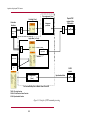
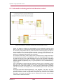
Application of high-speed TRIP
contacts
Document: V1.1
Budapest, February 2013
Application of high-speed TRIP contacts
User’s manual version information
Version
Datum
Preliminary
30.10.2011
V1.0
12.08.2012
V1.1
07.02.2013
Version 1.1
Modification
Compiled by
Preliminary version
Petri
Description of the assignment for the fast trip
contacts
Figure ‘Principle of TRIP command processing’
updated
Petri
Gunthner,
Csipke
2/20
Application of high-speed TRIP contacts
Contents
1 Relay output modules of the EuroProt+ system ......................................................................4
1.1
Types of the relay output modules of the EuroProt+ system ...................................... 4
1.2
Operating modes of the relay contacts ....................................................................... 4
2 Application of TRIP relays for commands of fast protection functions ....................................6
2.1
Aim of application of TRIP relays ................................................................................ 6
2.2
Control of the TRIP relays ........................................................................................... 6
2.2.1
Preparation of the circuit for the trip command .................................................... 6
2.2.2
The trip command generation .............................................................................. 6
2.3
The factory programming for relay control .................................................................. 6
2.4
Changing the TRIP command assignment ................................................................. 7
2.5
Fast operation of the relays ......................................................................................... 8
3 User application of the TRIP relays .........................................................................................9
3.1
Graphic editor for the signal logic.............................................................................. 10
3.2
The process of command generation ....................................................................... 10
4 Control of signal relay outputs .............................................................................................. 10
5 Examples 11
5.1
Application of the TRIP logic ..................................................................................... 11
5.2
Application of circuit breaker control block ................................................................ 12
5.3
Automatic reclosing and circuit breaker control ........................................................ 14
5.4
Closing the circuit breaker with synchro-check ......................................................... 16
5.5
Closing the circuit breaker with synchro-check and synchro-switch ......................... 18
Version 1.1
3/20
Application of high-speed TRIP contacts
1 Relay output modules of the EuroProt+ system
1.1 Types of the relay output modules of the EuroProt+
system
Basically there are two different types of relay output modules in the EuroProt+
devices:
TRIP relay output module for high-speed operation of the circuit breakers
Signal relay output module
1.2 Operating modes of the relay contacts
For operation of the relay output modules there are four different modes:
Application of TRIP relays for commands of fast protection functions
User application of the TRIP relays
Fast operation of any relay contacts (TRIP relays or signal relays)
Control of signal relay outputs
The procedures of command processing are shown in. This document describes the
details using the TRIP relay contacts as an example.
The left side of the Figure shows the available sources of the trip commands:
The function blocks, configured in the device,
The communication channels to the SCADA system,
Commands generated using the front panel LCD of the device,
Any other binary signals, e.g. signals from the binary inputs of the device.
The right side of the Figure shows one of the TRIP relays symbolically.
The Figure provides a survey of the configured trip command processing methods. In
the middle of the Figure, the locations indicated by “User” shows the possibilities for
the user to modify the procedures. All other parts are factory programmed.
Version 1.1
4/20
Application of high-speed TRIP contacts
Trip assignment (1 ms)
Physical TRIP
contact of the
TRIP module
Fast logic (1 ms)
Protection
functions
Instantaneous
Assignment
procedure
OR
OR
Delayed
Logic editor (>= 4 ms)
OR
Trip contact
Cmd OFF
Communication
LCD
CLOSE
contact
L1 assignment
(1 ms)
Synchronized close
Can be modified by User in Master View of EuroCAP
TRC94: Trip Logic function
CB1Pol: Circuit Breaker Control function
SYN25: Synchrocheck function
Figure 1-1 Principle of TRIP command processing
5/20
Application of high-speed TRIP contacts
2 Application of TRIP relays for commands of fast
protection functions
2.1 Aim of application of TRIP relays
The main aim of application of TRIP relays is to bypass the time delay of the
mechanical contacts. For this aim there is a „slow” mechanical contact and a „fast”
electronic switch in serial connection.
2.2 Control of the TRIP relays
The operation of the TRIP relays is performed in two steps:
Preparation of the circuit for the trip command
Trip command generation
2.2.1 Preparation of the circuit for the trip command
At the time when a protection function detects violation of the setting value of the
characteristic quantity, the preparation process closes the „slow” mechanical contact,
preparing the circuit for command generation.
2.2.2 The trip command generation
At the moment when the fast protection function – after some repeated checks, i.e.
the timeout of the internal time counter – decides to generate the trip command then
the „fast” electronic switch performs the operation, generating the trip command to the
circuit breaker. This command is generated via the „TRC94_ PhS” or via the
simplified „TRC94” trip logic function blocks.
NOTE: If the TRIP command is not received within the expected time delay, then the
command preparation resets after 50 ms. When the device is tested in the laboratory
e.g. for measuring the limits of the distance protection characteristic, this can result a
cyclic closing and opening of the mechanical contact and rattling can be heard. This
does not mean faulty operation of the device!
2.3 The factory programming for relay control
For the trip command of protection functions, where the requirement is the fast
operation (distance protection first zone, line differential protection, transformer
differential protection, fast overcurrent stage, synchronous switching, etc.) the
process of preparation and command generation is programmed in the form of „Fast
logic”.
The alignment of the TRIP command is the task of the “TRIP logic function block”. All
devices operating with TRIP binary output module, has a configured TRC 94
simplified, or a TRC 94_PhS TRIP logic function block. This converts e.g. the trip
command due to phase-to-phase fault to a three-phase trip command, or extends the
duration of the command according to the parameter setting. All these are described
in the dedicated document.
The fast TRIP commands are assigned to the TRIP relay output contacts according to
the factory configuration, but the user has a possibility to modify or extend this
assignment using the EuroCAP configuration software. The factory assignment is
described in the user manual of the given device configuration.
To ensure fast operation, this „Fast logic” is performed in each sampling cycle (1ms).
Version 1.1
6/20
Application of high-speed TRIP contacts
2.4 Changing the TRIP command assignment
The user has a possibility to modify or extend the TRIP command assignment using
the EuroCAP configuration software. The menu item to be started is shown in Figure
2-1.
Figure 2-1 Menu item for TRIP command assignment
As Figure 2-2 shows, the signal of type „TripLogic Output” (this is the command
generated by the „TRIP logic function block”) can be assigned to a „Trip Contact” type
relay output. The dialog window of the EuroCAP software selects these types of
signals only; the available signals however can be assigned freely.
Figure 2-2 Changing the TRIP command assignment
Version 1.1
7/20
Application of high-speed TRIP contacts
The assigned signal is the input of an OR gate. As it is described below, several other
signals can be directed to this OR gate. Using this method, also other TRIP modules
extended by the user can be applied to operate the TRIP coil of the circuit breaker.
2.5 Fast operation of the relays
If the aim is to operate the contacts by a signal in each sampling cycle (1 ms), then
the “Fast L1 contact option is to be applied. This option is provided by the EuroCAP
configuration software in the menu „Hardware configuration/ IO signals/ Binary
outputs/ Relay contacts/ Fast_L1 contacts”.
Figure 2-3 Configuring Fast L1 contacts
This menu offers the assignment of the appropriate binary signals to the relay
contacts. As Figure 2-4 shows, the signal can be of several types.
Version 1.1
8/20
Application of high-speed TRIP contacts
Figure 2-4 Fast L1 contact assignment
The processing of these fast signals is performed in a single step, the possibility for
command preparation in the first step and additionally the TRIP command generation
in the second step is not offered for the user. To perform this assignment, the
application of the EuroCap configuration program in “Master” level is needed.
The selected signal is the input of an OR gate. To this gate additional other signals
are connected, as it is described in the previous chapter, or in the description below.
IMPORTANT NOTE: The contacts of a TRIP hardware module are configured in the
factory as “Fast L1 contacts”, the user does not need to define them additionally!
3 User application of the TRIP relays
The contacts controlling the circuit breaker operation can be programmed also by the
user. Additionally to the command of the factory configured protection functions the
user can assign signals to the channels of the TRIP hardware module. The two steps
for the command generation however, as it is described in the paragraph above,
cannot be applied by the user.
In this case, the source of the signals can be:
Pre-configured TRIP commands
o
Received from the SCADA system via communication channels,
o
Generated by the user, applying the front panel LCD of the device,
Any additional binary signals, e.g. an external command received by the
binary input module of the device.
Version 1.1
9/20
Application of high-speed TRIP contacts
The pre-configured TRIP commands are aligned by the “CB control function block”,
the output of which is the “CmdOff” TRIP command. This one and several other
signals can be programmed by the user to the output TRIP contact of the device,
using the graphic logic editor of the EuroCAP configuration software.
Additionally the output signals of the „TRC94_ PhS” trip logic or those of the „TRC94”
simplified trip logic block can be programmed here. (These function-blocks are
described in separate documents.) The output signal of the graphic logic editor is the
„BOut_X” logic variable, where X is the identifier of the relay module and the contact,
e.g. BOut_E02.
3.1 Graphic editor for the signal logic
For the protection functions, the operation of which are not required being extreme
fast (in the range of one network period), the trip command must be assigned to the
trip contacts usually by the user. These logic assignments can be programmed also in
the factory, but the user can modify or extend them according to the requirements. To
do this, the graphic editor of the EuroCap configuration tool must be applied with
„Master” access rights.
3.2 The process of command generation
If a “simple” protection function generates a trip command then this logic signal is
present on the dedicated output of the function block (see the description of the
function blocks).
The operation of the logic connections edited in the graphic editor is performed
outside the sampling cycle, consequently, depending on the actual load of the
processor a random time delay of additional 2-4 ms can be measured.
The contacts of the TRIP hardware modules are operated by several sources parallel:
The high-speed factory configured fast protection functions,
The defined Fast L1 signals,
The graphically edited logic connections (programmed in the factory and editable also
by the user).
4 Control of signal relay outputs
If there is no special requirement to generate the signal with high speed, i.e. a time
delay of 2-4 ms can be tolerated between the intent to generate the signal and the
closing of the output contact then it is sufficient to apply normal signal relay contacts.
To perform this programming the graphic editor of the EuroCap configuration tool is to
be applied. To perform the programming the „Master” access level is needed.
Version 1.1
10/20
Application of high-speed TRIP contacts
5 Examples
5.1 Application of the TRIP logic
Figure 5-1 Example: A simple configuration to trip the circuit breaker
Figure 5-1 shows a simple configuration to trip the circuit breaker. In this Figure it is
supposed that the fast protection functions operate according to the factory
configuration and they control the TRIP contacts applying two steps of the preparation
and command generation phases. This part of the program is not visible. (The
description of the fast operating protection functions are listed in the configuration
description of the devices.)
The outputs of the TRC94_PhS trip logic block are assigned to the channels of the
TRIP hardware module. This assignment, which can be modified also by the user, is
made not here but in the “TRIP assignment” menu of the EuroCAP configuration
software. Consequently the Figure is complete; related to the outputs, the user needs
additional graphic programming only if e.g. the operation is to be visualized also by
signal relays.
If the configuration includes protection functions blocks the trip command of which
does not need fast contact operation then these commands must be additionally
directed to the TRIP relay outputs. To do this, the user collects these commands (with
OR connection) and connects them to the dedicated inputs of the TRC94_PhS
module.
This Figure shows the collected signals (E.g. “Trip_SinglePh”, “Trip_3Ph”, etc.) only.
As an example the „Trip_3Ph” signal collects the commands of all (not fast operating)
protection functions which can generate three-phase trip command. The detailed
description of the inputs and operation of the “TRC94_PhS” trip logic function block
can be found in another document.
Version 1.1
11/20
Application of high-speed TRIP contacts
5.2 Application of circuit breaker control block
Figure 5-2 Example: Application of circuit breaker control block
Figure 5-2 shows an example for the application of the circuit breaker control block
“CB3Pol”. In this Figure it is supposed that the fast protection functions operate
according to the factory configuration and they control the TRIP contacts applying two
steps of the preparation and command generation phases. This part of the program is
not visible. (The description of the fast operating protection functions are listed in the
configuration description of the devices.)
The outputs of the TRC94_PhS trip logic block are assigned to the channels of the
TRIP hardware module. This assignment, which can be modified also by the user, is
made not here but in the “TRIP assignment” menu of the EuroCAP configuration
software. Consequently the Figure is complete; related to the outputs, the user needs
additional graphic programming only if e.g. the operation is to be visualized also by
signal relays.
If the configuration includes protection functions blocks the trip command of which
does not need fast contact operation then these commands must be additionally
connected to the TRIP relay outputs. To do this, the user collects these commands
(with OR connection) and assigns them to the dedicated inputs of the TRC94_PhS
module.
This Figure shows the collected signals (E.g. “Trip_SinglePh”, “Trip_3Ph”, etc.) only.
As an example the „Trip_3ph” signal collects the commands of all (not fast operating)
protection functions which can generate three-phase trip command. The detailed
description of the inputs and operation of the “TRC94_PhS” trip logic function block
can be found in another document.
Version 1.1
12/20
Application of high-speed TRIP contacts
An extension to the example in Figure 5-2 is that in this configuration also the
„CB3pol” (circuit breaker control block) is applied. This block is needed if e.g. the front
panel LCD of the device can display an active control scheme. For this purpose the
signals „BIn_L…” in the Figure are the status signals of the circuit breaker poles,
connected to the dedicated binary inputs of the device. The signals „Local”/”Remote”
enable the local or remote control of the primary equipment. In the standard factory
configurations these signals are programmed in the factory, but they can be modified
also by the user.
If there is no synchro-check function activated in the device, connect the input
„SynOK” of the “CB3Pol” to logic TRUE state. Figure 5-2, the local command issued
via LCD of the device or the remote command received from the remote SCADA
system is processed by the „TRC94_PhS” module (Output „CmdOff”). This control is
programmed in the factory to “BOut_xx” variables. The user can perform any
modification in the graphic programming.
The close command is connected directly to a dedicated “BOut_xx” variable. (This
directs usually the fourth contact of the TRIP hardware module.)
The programming of the interlocking function must be performed by the user.
Version 1.1
13/20
Application of high-speed TRIP contacts
5.3 Automatic reclosing and circuit breaker control
Figure 5-3 Example: Automatic reclosing and circuit breaker control
Figure 5-3 shows an example for the application of the automatic reclosing control
block. In this Figure it is supposed that the fast protection functions operate according
to the factory configuration and they control the TRIP contacts applying two steps of
the preparation and command generation phases. This part of the program is not
visible in “Master” level. (The description of the fast operating protection functions are
listed in the configuration description of the devices.)
The outputs of the TRC94_PhS trip logic block are assigned to the output channels of
the TRIP hardware module. This assignment, which can be modified also by the user,
is made not here but in the “TRIP assignment” menu of the EuroCAP configuration
software. Consequently the Figure is complete; related to the outputs, the user needs
additional graphic programming only if e.g. the operation is to be visualized also by
signal relays.
If the configuration includes protection functions blocks the trip command of which
does not need fast contact operation then these commands must be additionally
assigned to the TRIP relay outputs. To do this, the user collects these commands
(with OR connection) and assigns them to the dedicated inputs of the TRC94_PhS
module.
This Figure shows the collected signals (E.g. “Trip_SinglePh”, “Trip_3Ph”, etc.) only.
As an example the „Trip_3ph” signal collects the commands of all (not fast operating)
protection functions which can generate three-phase trip command. The detailed
description of the inputs and operation of the “TRC94_PhS” trip logic function block
can be found in another document.
Version 1.1
14/20
Application of high-speed TRIP contacts
In this configuration also the „CB3pol” (circuit breaker control block) is applied. This
block is needed if e.g. the front panel LCD of the device can display an active control
scheme. For this purpose the signals „BIn_L…” in the Figure are the status signals of
the circuit breaker poles, connected to the dedicated binary inputs of the device. The
signals „Local”/”Remote” enable the local or remote control of the primary equipment.
In the standard factory configurations these signals are programmed in the factory,
but they can be modified also by the user.
If there is no synchro-check function activated in the device, connects the input
„SynOK” of the “CB3Pol” to logic TRUE state.
According to Figure 5-3, the local command issued via LCD of the device or the
remote command received from the remote SCADA system is processed by the
„TRC94_PhS” module (Output „CmdOff”). This control is programmed in the factory to
“BOut_xx” variables. The user can perform any modification in the graphic
programming.
The close command is connected directly to a dedicated “BOut_xx” variable. (This
directs usually the fourth contact of the TRIP hardware module.)
In Figure 5-3 the close command is connected directly to a dedicated output. (This is
usually the fourth contact of the TRIP hardware module.)
The programming of the interlocking function must be performed by the user.
An extension to the example in Figure 5-2 is the application of the „REC79_HV”
automatic reclosing function. The start signal „Trip_StartAR” can be programmed by
the user. The automatic reclosing function is started only if the preceding trip
command was performed by the circuit breaker, i.e. for example that the function is
not disabled. The AND gate on this Figure performs this checking.
The „REC79_HV” automatic reclosing function needs the status signal indicating
three-phase open state of the circuit breaker, connected to the „3PhTr” input of the
„REC79_HV” function block. This signal is generated by the „TRC94_PhS” module on
the output „Tr3Ph”.
If the automatic reclosing is to be disabled after a fault caused by a manual close
command, then the „CmdOn” output of the „CB3Pol” module must be connected to
the „ManCl” input of the „REC79_HV” automatic reclosing function.
If there is no synchro-check function configured in the device, connect the „SynRel”
input of the „REC79_HV” automatic reclosing function to logic TRUE state.
The evaluation of the status signals indicating the open state of the circuit breker
poles in OR gate is needed for the operation of the automatic reclosing function.
According to the scheme of Figure 5-3 the open state is indicated by at least one pole
open state of the circuit breaker. (For simplicity, this Figure shows a realization
without checking the FALSE signal of the closed states.)
Figure 5-3 supposes that the CB ready signal is not connected to the device;
accordingly the steady TRUE state signal is connected to the „CBRdy” input of the
„REC79_HV” automatic reclosing function. If the real signal is available, the signal
must be connected similarly.
The close command of the „REC79_HV” automatic reclosing function is connected
via OR gate to the dedicated close contact.
Version 1.1
15/20
Application of high-speed TRIP contacts
5.4 Closing the circuit breaker with synchro-check
Figure 5-4 Example: closing the circuit breaker with synchro-check
Figure 5-4 shows an example for the application of “SYN25” cynchro-check function
block. In this Figure it is supposed that the fast protection functions operate according
to the factory configuration and they control the TRIP contacts applying two steps of
the preparation and command generation phases. This part of the program is not
visible in “Master” level. (The description of the fast operating protection functions are
listed in the configuration description of the devices.)
The outputs of the TRC94_PhS trip logic block are assigned to the output channels of
the TRIP hardware module. This assignment, which can be modified also by the user,
is made not here but in the “TRIP assignment” menu of the EuroCAP configuration
software. Consequently the Figure is complete; related to the outputs, the user needs
additional graphic programming only if e.g. the operation is to be visualized also by
signal relays.
If the configuration includes protection functions blocks the trip command of which
does not need fast contact operation then these commands must be additionally
assigned to the TRIP relay outputs. To do this, the user collects these commands
(with OR connection) and assigns them to the dedicated inputs of the TRC94_PhS
module.
This Figure shows the collected signals (E.g. “Trip_SinglePh”, “Trip_3Ph”, etc.) only.
As an example the „Trip_3ph” signal collects the commands of all (not fast operating)
protection functions which can generate three-phase trip command. The detailed
description of the inputs and operation of the “TRC94_PhS” trip logic function block
can be found in another document.
In this configuration also the „CB3pol” (circuit breaker control block) is applied. This
block is needed if e.g. the front panel LCD of the device can display an active control
Version 1.1
16/20
Application of high-speed TRIP contacts
scheme. For this purpose the signals „BIn_L…” in the Figure are the status signals of
the circuit breaker poles, connected to the dedicated binary inputs of the device. The
signals „Local”/”Remote” enable the local or remote control of the primary equipment.
In the standard factory configurations these signals are programmed in the factory,
but they can be modified also by the user.
According to Figure 5-4, the local command issued via LCD of the device or the
remote command received from the remote SCADA system is processed by the
„TRC94_PhS” module (Output „CmdOff”). This control is programmed in the factory to
“BOut_xx” variables. The user can perform any modification in the graphic
programming.
The close command is connected directly to a dedicated “BOut_xx” variable. (This
directs usually the fourth contact of the TRIP hardware module.)
In Figure 5-4 the close command is connected directly to a dedicated output. (This is
usually the fourth contact of the TRIP hardware module.)
The programming of the interlocking function must be performed by the user.
Figure 5-4 includes the application of the „REC79_HV” automatic reclosing function.
The start signal „Trip_StartAR” can be programmed by the user. The automatic
reclosing function is started only if the preceding trip command was performed by the
circuit breaker, i.e. for example that the function is not disabled. The AND gate on this
Figure performs this checking.
The „REC79_HV” automatic reclosing function needs the status signal indicating
three-phase open state of the circuit breaker, connected to the „3PhTr” input of the
„REC79_HV” function block. This signal is generated by the „TRC94_PhS” module on
the output „Tr3Ph”.
If the automatic reclosing is to be disabled after a fault caused by a manual close
command, then the „CmdOn” output of the „CB3Pol” module must be connected to
the „ManCl” input of the „REC79_HV” automatic reclosing function.
The evaluation of the status signals indicating the open state of the circuit breaker
poles in OR gate is needed for the operation of the automatic reclosing function.
According to the scheme of Figure 5-4 the open state is indicated by at least one pole
open state of the circuit breaker. (For simplicity, this Figure shows a realization
without checking the FALSE signal of the closed states.)
Figure 5-4 supposes that the CB ready signal is not connected to the device;
accordingly the steady TRUE state signal is connected to the „CBRdy” input of the
„REC79_HV” automatic reclosing function. If the real signal is available, the signal
must be connected similarly.
The close command of the „REC79_HV” automatic reclosing function is connected
via OR gate to the dedicated close contact.
An extension to the example in Figure 5-3 is the close command to the circuit breaker
is generated by synchro-check. The enabling signal for the close command is
generated by the „SYN25” software module. This module is described in details in a
separate document. The needed input signals indicating the state of the voltage
transformers („VTSBlk” and „Bus1VTSBlk”), must be programmed graphically.
The output signal „RelA” of the „SYN25” software module enables the closing
operation of the „REC79_HV” automatic reclosing function via its „SynRel” input.
For manual close commands the output signal „RelM” of the „SYN25” software
module enables the closing operation of the „CB3pol” via its „SynOK” input.
Version 1.1
17/20
Application of high-speed TRIP contacts
5.5 Closing the circuit breaker with synchro-check and
synchro-switch
Figure 5-5 Example: closing the circuit breaker with synchro-check and synchroswitch
Figure 5-5 shows an example for the application of “SYN25” cynchro-check function
block with synchro switch extension. In this Figure it is supposed that the fast
protection functions operate according to the factory configuration and they control
the TRIP contacts applying two steps of the preparation and command generation
phases. This part of the program is not visible in “Master” level. (The description of
the fast operating protection functions are listed in the configuration description of the
devices.)
The outputs of the TRC94_PhS trip logic block are assigned to the output channels of
the TRIP hardware module. This assignment, which can be modified also by the user,
is made not here but in the “TRIP assignment” menu of the EuroCAP configuration
software. Consequently the Figure is complete; related to the outputs, the user needs
additional graphic programming only if e.g. the operation is to be visualized also by
signal relays.
If the configuration includes protection functions blocks the trip command of which
does not need fast contact operation then these commands must be additionally
assigned to the TRIP relay outputs. To do this, the user collects these commands
Version 1.1
18/20
Application of high-speed TRIP contacts
(with OR connection) and assigns them to the dedicated inputs of the TRC94_PhS
module.
This Figure shows the collected signals (E.g. “Trip_SinglePh”, “Trip_3Ph”, etc.) only.
As an example the „Trip_3ph” signal collects the commands of all (not fast operating)
protection functions which can generate three-phase trip command. The detailed
description of the inputs and operation of the “TRC94_PhS” trip logic function block
can be found in another document.
In this configuration also the „CB3pol” (circuit breaker control block) is applied. This
block is needed if e.g. the front panel LCD of the device can display an active control
scheme. For this purpose the signals „BIn_L…” in the Figure are the status signals of
the circuit breaker poles, connected to the dedicated binary inputs of the device. The
signals „Local”/”Remote” enable the local or remote control of the primary equipment.
In the standard factory configurations these signals are programmed in the factory,
but they can be modified also by the user.
According to Figure 5-5, the local command issued via LCD of the device or the
remote command received from the remote SCADA system is processed by the
„TRC94_PhS” module (Output „CmdOff”). This control is programmed in the factory to
“BOut_xx” variables. The user can perform any modification in the graphic
programming.
The close command is connected directly to a dedicated “BOut_xx” variable. (This
directs usually the fourth contact of the TRIP hardware module.)
In Figure 5-5 the close command is connected directly to a dedicated output. (This is
usually the fourth contact of the TRIP hardware module.)
The programming of the interlocking function must be performed by the user.
Figure 5-5 includes the application of the „REC79_HV” automatic reclosing function.
The start signal „Trip_StartAR” can be programmed by the user. The automatic
reclosing function is started only if the preceding trip command was performed by the
circuit breaker, i.e. for example that the function is not disabled. The AND gate on this
Figure performs this checking.
The „REC79_HV” automatic reclosing function needs the status signal indicating
three-phase open state of the circuit breaker, connected to the „3PhTr” input of the
„REC79_HV” function block. This signal is generated by the „TRC94_PhS” module on
the output „Tr3Ph”.
If the automatic reclosing is to be disabled after a fault caused by a manual close
command, then the „CmdOn” output of the „CB3Pol” module must be connected to
the „ManCl” input of the „REC79_HV” automatic reclosing function.
If there is no synchro-check function configured in the device, then connect the
„SynRel” input of the „REC79_HV” automatic reclosing function to logic TRUE state.
The evaluation of the status signals indicating the open state of the circuit breaker
poles in OR gate is needed for the operation of the automatic reclosing function.
According to the scheme of Figure 5-5 the open state is indicated by at least one pole
open state of the circuit breaker. (For simplicity, this Figure shows a realization
without checking the FALSE signal of the closed states.)
Figure 5-5 supposes that the CB ready signal is not connected to the device;
accordingly the steady TRUE state signal is connected to the „CBRdy” input of the
„REC79_HV” automatic reclosing function. If the real signal is available, the signal
must be connected similarly.
The close command of the „REC79_HV” automatic reclosing function is connected
via OR gate to the dedicated close contact.
In this application the close command to the circuit breaker is generated by synchrocheck. The enabling signal for the close command is generated by the „SYN25”
software module. This module is described in details in a separate document. The
Version 1.1
19/20
Application of high-speed TRIP contacts
needed input signals indicating the state of the voltage transformers („VTSBlk” and
„Bus1VTSBlk”), must be programmed graphically.
The output signal „RelA” of the „SYN25” software module enables the closing
operation of the „REC79_HV” automatic reclosing function via its „SynRel” input.
For manual close commands the output signal „RelM” of the „SYN25” software
module enables the closing operation of the „CB3pol” via its „SynOK” input.
An extension to the example in Figure 5-4 is the following: If there is no continuous
synchron state because the frequency at one side of the circuit breaker is different to
that of the other side, then the voltage vector of one side rotates continuously as
compared to the other one. In this case a synchronous switching is attempted to
restore the normal operation of the network.
The manual synchron switching mode is started by the signal on the „StSwM” input of
the SYN25 module. To do this the the „StartSW” output of the „Cb3Pol” module must
be connected here.
For automatic synchron switching mode the „ClReq” output of the „Rec79HV” module
must be connected to the „SwStA” input of the „SYN25” software module.
IMPORTANT NOTE: the close command is generated for both manual and automatic
switching at the output „SynSW” of the „SYN25” software module. It is advised not to
connect this output using the „slow” graphic programming, but the contact assigned to
the close command („BOutClose”) must be handled as fast operating „L1 contact”.
The „SynSW” signal must be programmed to this contact. This assignment is
performed using the EuroCap configuration tool in the menu „Hardware
configuration/Binary outputs/Relay contacts/Fast_L1 contacts”.
Version 1.1
20/20