1
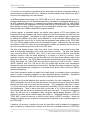
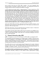
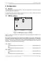
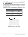
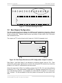
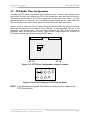
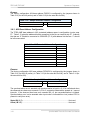
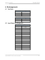
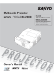
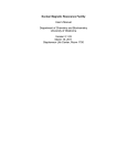
Spectracom Corporation
1
2
3
TPRO-VME/TSAT-VME
4
5
6
7
8
9
10
11
12
13
14
15
16
Figure 3-7: P5 Default Settings for IRQ5
3.4
Rate Outputs Configuration
Two jumper-selected pulse rate outputs are available on the front-panel J1 connector. Each of
these is a positive going pulse, nominally 1.5 µS in duration, with the rising edge synchronized
to the on-board clock. Separate output drivers are present for each output, even if the same
rate is selected for both.
The outputs are TTL levels, driven by the Q output of a 74LS123 integrated circuit.
P11
P13
P12
Front Panel
Figure 3-8: Rate Output Selection and P2 Configuration Jumper Locations
Rate Output 1 and Rate Output 2 are selected by connecting jumper wires on P13. Rate
outputs and various other signals can be routed to the rear-panel P2 connector by connecting
jumpers on P11 and P12, as described in the next section.
Select the output rate for Rate 1 by installing a jumper from P13 Pin 10 to one of the following
locations on P13. In the same manner, select Rate 2 by installing a jumper from P13 Pin 11 to
one of the following locations. It is acceptable to connect both Pin 10 and Pin 11 to the same
rate, if desired. It is also acceptable to leave the jumpers unconnected if the rate output is not
used.
Synchronizable Timecode Generator User Manual
3-7