1
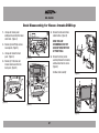
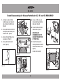
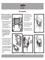
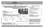
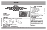
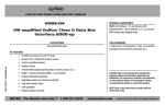
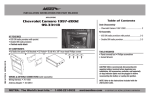
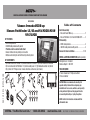
INSTALLATION INSTRUCTIONS FOR PART 99-7620B
APPLICATIONS
Nissan Armada 2008-up
Nissan Pathfinder LE, SE and SV 2008-2012
99-7620B
KIT FEATURES
• DDIN radio provision
• ISO DIN radio provision with pocket
• Painted scratch-resistant matte black
• Axxess interface to keep factory screen active
• Buttons and circuitry to control the factory climate system
REV. 12/1/2014 INST99-7620B
KIT COMPONENTS
• A) Radio brackets for Armada • B) Radio brackets for Pathfinder • C) Screen brackets for Armada
• D) Screen brackets for Pathfinder • E) Center control panel • F) (2) Outboard controls • G) Pocket
• H) (8) #8 x 3/8” Phillips screws • Axxess interface and harness (not shown)
A
F
B
G
C
D
E
Table of Contents
Dash Disassembly
–. Nissan Armada 2008-up....................................... 2
–. Nissan Pathfinder LE, SE and SV 2008-2012......... 3
Kit Assembly
–. DDIN radio provision............................................. 4
–. ISO DIN radio provision with pocket....................... 4
Axxess interface installation.............................5-10
WIRING & ANTENNA CONNECTIONS (sold separately)
Wiring Harness: • Included
Antenna Adapter: • 40-NI12
TOOLS REQUIRED
• Panel removal tool • Phillips screwdriver
• Torx screwdriver
CAUTION: Metra recommends disconnecting the
negative battery terminal before beginning any
installation. All accessories, switches, and especially
air bag indicator lights must be plugged in before
reconnecting the battery or cycling the ignition.
H
NOTE: Refer to the instructions included with the
aftermarket radio.
METRA. The World’s best kits.™
1-800-221-0932
metraonline.com
© COPYRIGHT 2014 METRA ELECTRONICS CORPORATION
99-7620B
Dash Disassembly for Nissan Armada 2008-up
1. Unsnap and remove power
outlet/pocket assembly from lower
center dash. (Figure A)
5. Remove the radio and climate
control buttons. (Figure D)
2. Remove (4) 8mm Phillips screws
now exposed. (Figure B)
3. Unsnap and remove the dash
panel. (Figure C)
6. Remove the factory screen
assembly. Remove the brackets
and black box from the screen.
(Figure E)
(Figure B)
4. Remove (4) T-20 screws and
remove radio chassis from the
dash panel. (Figure D)
(Figure A)
HAND TOOLS ARE
RECOMMENDED, FACTORY
DASH MAY BREAK WITH USE
OF POWER TOOLS.
Continue to kit assembly
(Figure D)
(Figure C)
(Figure E)
2
99-7620B
Dash Disassembly for Nissan Pathfinder LE, SE and SV 2008-2012
1. Push down on collar of shifter
handle to expose clip, remove the
clip and remove the shifter knob.
(Figure A)
5. Remove (4) T-20 screws and
remove radio chassis from the
dash panel. (Figure E)
6. Remove the radio and climate
control buttons. (Figure E)
2. Unsnap and remove the shifter trim
including the pocket/ switch panel
below the radio. (Figure B)
3. Remove (2) 8mm/ Phillips screws
now exposed. (Figure C)
(Figure B)
4. Unsnap and remove the dash
panel. (Figure D)
HAND TOOLS ARE
RECOMMENDED, FACTORY
DASH MAY BREAK WITH USE
OF POWER TOOLS.
7. Remove the factory screen
assembly. Remove the brackets
and black box from the screen.
(Figure F)
(Figure E)
Continue to kit assembly
(Figure C)
(Figure A)
(Figure F)
(Figure D)
3
99-7620B
Kit Assembly
NOTE: All accessories, switches, and
especially air bag indicator lights must
be plugged in before reconnecting the
battery or cycling the ignition.
4. For ISO DIN installations only,
mount the pocket to the bracket/
panel assembly with the
(4) #8 x 3/8” Phillips screws
supplied. (Figure D)
1. Using the model specific set of screen
brackets, mount the factory screen
and control box back into
the dash with the (4) #8 x 3/8”
Phillips screws supplied. (Figure A)
Note: It may be necessary to
file the inside edges of the top
two screen mount locations to
accommodate the screen.
(Figure A)
5. Slide the radio into the assembly
and secure with screws supplied
with the radio. (Figure E)
6. Continue to Wiring and Interface
Installation section of this manual.
(Figure A)
(Figure D)
2. Using factory hardware, mount the
center control panel and outboard
switches to the factory dash panel.
Leave the inner top mounting screws
out until the next step. (Figure B)
HAND TOOLS ARE RECOMMENDED
3. Mount the model specific radio
brackets to the factory dash panel.
(Figure C)
(Figure C)
(Figure B)
4
(Figure E)
99-7620B
Axxess Interface Installation
Table of Contents
FEATURES
• Retains factory screen
• Retains factory back up camera
• Retains factory AUX in
• Retains RSE
• Retains personalization features
• Ability to add aftermarket backup camera or additional video input
• Works in amplified or non-amplified models
• Prewired ASWC-1 harness included (ASWC-1 sold separately)
Models without factory navigation............................................................. 6
Models with factory navigation.................................................................. 8
Updating the 99-7620B................................................................................ 9
Screen operation....................................................................................... 10
INTERFACE COMPONENTS
• Interface
• 7620-MAIN harness
• 24-pin to 20-pin interface to display harness
• 12-pin harness with RCA jacks
• 7620-NAV harness
• 12-pin to 20-pin interface to display harness
• 32-pin harness with RCA jacks
• 14-pin to 14-pin interface to HVAC harness
• 10-pin to 10-pin HVAC to outboard switch harness (2)
TOOLS REQUIRED
• Cutting tool
• Crimping tool
• Tape
• Connectors (example: butt-connectors, bell caps, etc.)
5
99-7620B
Connections to be made
For models without factory navigation
If the vehicle has a factory installed BOSE sound system:
7620-MAIN Harness
From the 12-pin harness to the aftermarket radio:
From the 20-pin harness to the aftermarket radio:
• Connect the Blue/White wire to the amp turn on wire (this wire must be
connected to hear sound from the factory amplifier).
• Connect the Orange wire to the illumination wire.
(If the aftermarket radio has no illumination wire, tape off the Orange wire).
• Connect the White, Grey, Green, and Purple RCAs to the audio outputs.
Note: If the vehicle has a factory installed BOSE sound system tape up
and disregard the following wires:
• Connect the Black wire to the ground wire.
• Connect the Yellow wire to the 12-volt battery wire.
• Connect the Red wire to the accessory wire.
• White
• Connect the White wire to the left front positive speaker output.
• White/Black
• Connect the White/Black wire to the left front negative speaker output.
• Gray
• Connect the Gray wire to the right front positive speaker output.
• Gray/Black
• Connect the Gray/Black wire to the right front negative speaker output.
• Green
• Connect the Green wire to the left rear positive speaker output.
• Green/Black
• Connect the Green/Black wire to the left rear negative speaker output.
• Connect the Purple wire to the right rear positive speaker output.
• Purple
• Connect the Purple/Black wire to the right rear negative speaker output.
• Purple/Black
• White/Blue
6
99-7620B
Connections to be made
From the 32-pin harness to the aftermarket radio:
Plug in:
• Connect the Blue/Pink wire to the speed sense wire (if applicable).
Locate the factory wiring harness and antenna plug in the dash. All accessories,
switches, and especially air bag indicator lights must be plugged in before
reconnecting the battery or cycling the ignition. Mount the new radio assembly
into the dash and reassemble dash in reverse order of disassembly.
• If you wish to retain the factory AUX plug, connect the Red and White RCAs
with the “AUX INPUT” label to the AUX input (if applicable).
• If you wish to retain the factory installed DVD audio, connect the Red and
White RCAs with the “FROM DVD” label to an available source
(example: Video/Audio 1, AUX 1 or 2, etc.).
• HVAC center panel to outboard harnesses. Left side controller plugs to left side
of main board and right side controller plugs to right side of main board.
• Vehicle to interface harness
NOTE – This 16-pin plug must be connected for factory back-up camera
to function. There are two of this style plug available in the dash, use the
factory 16-pin plug that is grouped with the factory radio plugs and went
to the back of the factory radio chassis.
From the 16-pin harness to the aftermarket radio:
NOTE – This 16-pin plug must be connected for factory back-up camera to
function. There are two of this style plug available in the dash, use the factory
16-pin plug that is grouped with the factory radio plugs and went to the back
of the factory radio chassis.
• Aux in RCA to AUX input of aftermarket radio (if applicable)
• If you wish to show the factory installed DVD video on your aftermarket video
screen, plug the Yellow RCA into the “Video” input of aftermarket radio.
• Rear DVD (if applicable)
• HVAC center panel to interface harness
From the 22-pin harness to the aftermarket radio:
• If you wish to add an aftermarket backup camera or external video source,
plug the Yellow RCA into the desired source.
ASWC-1 (if installing)
After the interface is initialized, plug the ASWC-1 into the 12-pin harness of
the 7620 harnesses and refer to the ASWC-1 instructions.
7
99-7620B
Connections to be made
For models with factory navigation
7620-NAV Harness
From the 20-pin harness to the aftermarket radio:
From the 40-pin harness to the aftermarket radio:
• Connect the Orange wire to the illumination wire.
(If the aftermarket radio has no illumination wire, tape off the Orange wire).
• Connect the Blue/Pink wire to the speed sense wire (if applicable).
• Connect the Black wire to the ground wire.
From the 32-pin harness to the aftermarket radio:
• Connect the Yellow wire to the 12-volt battery wire.
• If you wish to retain the factory AUX plug, connect the Red and White RCAs
with the “AUX INPUT” label to the AUX input (if applicable).
• Connect the Red wire to the accessory wire.
• If you wish to retain the factory installed DVD audio, connect the Red and
White RCAs with the “FROM DVD” label to an available source
(example: Video/Audio 1 or 2, AUX 1 or 2, etc.).
• Connect the White wire to the left front positive speaker output.
• Connect the White/Black wire to the left front negative speaker output.
• Connect the Gray wire to the right front positive speaker output.
Note: In factory NAV vehicles – Factory back-up camera is retained
without use of the interface. AUX video-in is not available.
• Connect the Gray/Black wire to the right front negative speaker output.
• Connect the Green wire to the left rear positive speaker output.
• Connect the Green/Black wire to the left rear negative speaker output.
• Connect the Purple wire to the right rear positive speaker output.
• Connect the Purple/Black wire to the right rear negative speaker output.
8
99-7620B
Connections to be made
Plug in:
Updating the 99-7620B
Locate the factory wiring harness and antenna plug in the dash. All accessories,
switches, and especially air bag indicator lights must be plugged in before
reconnecting the battery or cycling the ignition. Mount the new radio assembly
into the dash and reassemble dash in reverse order of disassembly.
• Download and install the WebXXpress software update from axxessinterfaces.com.
• Connect the USB-MINI-CAB update cable (sold separately) between the 99-7620B and the computer. The cable will connect into the port on the rear of the kit labeled “A”.
• HVAC center panel to outboard harnesses. Left side controller plugs to left side
of main board and right side controller plugs to right side of main board.
• Vehicle to interface harness
Note: The 99-7620B will need to be powered up to be updated.
• Aux in RCA to AUX input of aftermarket radio (if applicable)
• From the Start Menu of the computer, click on “USB Bootloader”, and then
click “Update Board”. The software will begin to download at this point.
• Rear DVD (if applicable)
Note: If 30 seconds elapses before you finish this step, you will need
to remove power from the 99-7620B, then reapply power, and then
start the update process again.
Note: Please note which firmware downloaded to the interface.
This will help in troubleshooting, if need be.
• HVAC center panel to interface harness
ASWC-1 (if installing)
After the interface is initialized, plug the ASWC-1 into the 12-pin harness of
the 7620 harnesses and refer to the ASWC-1 instructions.
9
99-7620B
Screen operation
Settings:
Vehicle selection:
All button functions are retained and are controlled in the same
manner that factory buttons were controlled.
(example: Tire Pressure, Fuel Economy, Brightness, Clock Setting, etc).
• The included interface is designed to auto-detect what vehicle it is in.
In the settings menu, there is an option of forcing the
vehicle type to the interface.
Note: The 2 blanks on the main center climate panel are not used.
10
• Go to - SETTINGS>MISCELLANEOUS>SELECT VEHICLE
99-7620B
Screen operation
Back up camera/AUX video input:
NOTE:
• VIDEO input can also be turned off.
• Blank button on right outboard controller can be used to
activate AUX video in.
• AUX video will work in PARK only.
• Reverse Camera Lines
• Go to – SETTINGS>MISCELLANEOUS> REVERSE CAM LINES
• On or off.
Note: By default, back-up lines for camera are set to off.
Screen operation continues on back cover.
• Factory equipped back-up cameras will continue to function without
additional wiring or control. The interface is shipped in this mode.
• The interface’s video input is set for any other external AUX Video input.
If aftermarket camera is installed, settings need to be changed.
• Go to – SETTINGS> MISCELLANEOUS>CAMERA INPUT>
AFTERMARKET CAMERA
Aftermarket camera video is activated from the vehicle’s
reverse signal sent to the Axxess interface.
11
INSTALLATION INSTRUCTIONS FOR PART 99-7620B
Screen operation
(continued from page 11)
System INFO:
REV. 12/1/2014 INST99-7620B
KNOWLEDGE IS POWER
Enhance your installation and fabrication skills by
enrolling in the most recognized and respected
mobile electronics school in our industry.
Log onto www.installerinstitute.com or call
800-354-6782 for more information and take steps
toward a better tomorrow.
• To access the current software of this product after it has been installed.
• Go to - SETTINGS>MISCELLANEOUS>SYSTEM INFORMATION
• Please have this information available when
calling tech support for assistance.
METRA. The World’s best kits.™
1-800-221-0932
Metra recommends MECP
certified technicians
metraonline.com
© COPYRIGHT 2014 METRA ELECTRONICS CORPORATION
INSTRUCCIONES DE INSTALACIÓN PARA LA PIEZA 99-7620B
Aplicaciones
Nissan Armada 2008 y mas
Nissan Pathfinder LE, SE y SV 2008-2012
99-7620B
Características del kit
• Provisión de radio DDIN
• Provisión de radio ISO DIN con cavidad
• Pintura negra mate resistente a rayaduras
• Interfase Axxess para mantener activa la pantalla de fábrica
• Botones y circuitos para controlar el sistema de clima de fábrica
REV. 12/1/2014 INST99-7620B
F
B
G
C
D
E
CABLEADO Y CONEXIONES DE ANTENA
(Se venden por separado)
Arnés de cables: • se incluye
Adaptador de antena: • 40-NI12
Herramientas requeridas
• Herramienta para quitar paneles
• Destornillador Phillips • Destornillador Torx
PRECAUCIÓN: Metra recomienda desconectar el terminal
negativo de la batería antes de comenzar cualquier
instalación. Todos los accesorios, interruptores y,
especialmente, las luces indicadoras de airbag deben
estar enchufados antes de volver a conectar la batería o
comenzar el ciclo de ignición.
Nota: Remítase a las instrucciones incluidas con el radio
de posventa.
H
METRA. The World’s best kits.™
Desmontaje del tablero
–. Nissan Armada 2008-up....................................... 2
–. Nissan Pathfinder LE, SE and SV 2008-2012......... 3
Ensamble del kit
–. Provisión de radio DDIN........................................... 4
–. Provisión de radio ISO DIN con cavidad...................... 4
Instalación de la interfase Axxess....................5-10
Componentes del kit
• A) Soportes de radio para Armada • B) Soportes de radio para Pathfinder • C) Soportes de pantalla para
Armada • D) Soportes de pantalla para Pathfinder • E) Panel de control central • F) (2) controles en la parte
exterior • G) Cavidad • H) (8) tornillos Phillips #8 de 3/8” • Interfase y arnés Axxess (no se muestra)
A
Indice
1-800-221-0932
metraonline.com
© COPYRIGHT 2014 METRA ELECTRONICS CORPORATION
99-7620B
Desmontaje del tablero para Nissan Armada 2008 y mas
5. Quite los botones del radio y del
control de clima. (Figura D)
1. Suelte a presión y quite el
ensamble de tomacorriente/
cavidad del tablero central inferior.
(Figura A)
2. Quite los (4) tornillos Phillips de
8 mm que quedan expuestos.
(Figura B)
3. Suelte a presión y quite el panel
del tablero. (Figura C)
(Figura B)
SE RECOMIENDA USAR
HERRAMIENTAS DE MANOEL TABLERO DE FÁBRICA
PODRÍA ROMPERSE SI SE USAN
HERRAMIENTAS ELÉCTRICAS.
6. Quite el ensamble de la pantalla de
fábrica. Quite los soportes y la caja
negra de la pantalla. (Figura E)
4. Quite los (4) tornillos T-20 y quite
el chasís del radio del panel del
tablero. (Figura D)
Continúe con el ensamble del kit
(Figura D)
(Figura C)
(Figura A)
(Figura E)
2
99-7620B
Desmontaje del tablero para Nissan Pathfinder LE, SE y SV 2008-2012
4. Suelte a presión y quite el panel
del tablero. (Figura D)
1. Presione hacia abajo el collar de
la palanca de velocidades para
exponer el gancho, quite el gancho
y quite la palanca de velocidades.
(Figura A)
2. Suelte a presión y quite la moldura
de la palanca de velocidades,
incluyendo la cavidad/el panel
de interruptores debajo del radio.
(Figura B)
5. Quite los (4) tornillos T-20 y quite
el chasís del radio del panel del
tablero. (Figura E)
6. Quite los botones del radio y del
control de clima. (Figura E)
(Figura B)
3. Quite los (2) tornillos Phillips de
8 mm que quedan expuestos.
(Figura C)
SE RECOMIENDA USAR
HERRAMIENTAS DE MANOEL TABLERO DE FÁBRICA
PODRÍA ROMPERSE SI SE USAN
HERRAMIENTAS ELÉCTRICAS.
(Figura E)
7. Quite el ensamble de la pantalla de
fábrica. Quite los soportes y la caja
negra de la pantalla. (Figura F)
(Figura C)
Continúe con el ensamble del kit
(Figura A)
(Figura F)
(Figura D)
3
99-7620B
Ensamble del kit
NOTA: Todos los accesorios, interruptores y
especialmente las luces del indicador de las
bolsas de aire deben estar conectados antes
de reconectar la batería o ciclar la ignición.
1. Usando el conjunto específico de soportes
de pantalla para el modelo en cuestión,
monte la pantalla de fábrica y la caja de
control de nuevo en el tablero con los (4)
tornillo Phillips #8 x 3/8” suministrados.
(Figura A)
Nota: Pudiera ser necesario limar los
bordes interiores de los dos sitios de
montaje de pantalla superiores para
dar cabida a la pantalla. (Figura A)
2. Usando la tornillería de fábrica, monte el
panel de control central y los interruptores
exteriores en el panel del tablero de
fábrica. Deje los tornillos de montaje
superiores interiores fuera hasta el
siguiente paso. (Figura B)
SE RECOMIENDA USAR
HERRAMIENTAS DE MANO
3. Monte los soportes de radio específicos
para el modelo en el panel del tablero de
fábrica. (Figura C)
4. Para instalaciones ISO DIN únicamente,
monte la cavidad en el ensamble del
soporte/panel con los (4) tornillos
Phillips #8 x 3/8” suministrados.
(Figura D)
5. Deslice el radio en el conjunto del
soporte y sujételo con los tornillos
suministrados con el radio. (Figura E)
6. Pase a la sección de Cableado e
Interfase de este manual.
(Figura A)
(Figura D)
(Figura B)
(Figura C)
4
(Figura E)
99-7620B
Instalación de la interfase Axxess
Indica
CARACTERÍSTICAS
• Retiene la pantalla de fábrica
• Retiene la cámara de reversa de fábrica
• Retiene la entrada AUX de fábrica
• Retiene RSE
• Retiene las funciones de personalización
• Capacidad de añadir cámara de reversa de mercado secundario y entrada
adicional de video
• Funciona en modelos amplificados o no amplificados
• Arnés ASWC-1 pre cableado incluido (el ASWC-1 se vende por separado)
Vehículos equipados sin navegación.......................................................... 6
Vehículos equipados con navegación........................................................ 8
Actualización de la 99-7620B..................................................................... 9
Operación de la pantalla........................................................................... 10
HERRAMIENTAS REQUERIDAS
• Herramienta de corte
• Pelacables
• Cinta
• Conectores (ejemplo: conectores de extremo, de campana, etc.)
COMPONENTES DE LA INTERFASE
• Interfase
• Arnés 7620-MAIN
• Arnés de interfase a pantalla de 24 pins a 20 pins
• Arnés de 12 pins con conectores RCA
• Arnés 7620-NAV
• Arnés de interfase a pantalla de 12 pins a 20 pins
• Arnés de 32 pins con conectores RCA
• Arnés de interfase a HVAC de 14 pins a 14 pins
• Arnés de HVAC a interruptor exterior de 10 pins a 10 pins
5
99-7620B
Conexiones que se deben hacer
Vehículos equipados sin navegación
Si el vehículo tiene un sistema de sonido BOSE instalado de fábrica:
Arnés de 7620-MAIN
Del arnés de 12 pins al radio de mercado secundario:
Del arnés de 20 pins al radio de mercado secundario:
• Conecte el cable azul/blanco al cable de encendido del amplificador (este
cable debe estar conectado para escuchar sonido del amplificador de fábrica).
• Conecte el cable anaranjado con el cable de iluminación. (Si el radio de mercado
secundario no tiene cable de iluminación, encinte el cable anaranjado).
• Conecte los cables RCA blanco, gris, verde y púrpura a las salidas de audio.
Nota: Si el vehículo tiene un sistema de sonido BOSE instalado de fábrica,
encinte e ignore los siguientes cables:
• Conecte el cable negro al cable de tierra.
• Conecte el cable amarillo al cable de la batería de 12 voltios.
• Blanco
• Conecte el cable rojo al cable de accesorios
• Blanco/Negro
• Conecte el cable blanco a la salida positiva de la bocina izquierda del frente.
• Gris
• Conecte el cable blanco/negro a la salida negativa de la bocina izquierda del frente.
• Gris/Negro
• Conecte el cable gris a la salida positiva de la bocina derecha del frente.
• Conecte el cable gris/negro a la salida negativa de la bocina derecha del frente.
• Verde
• Conecte el cable verde a la salida de la bocina positiva izquierda de atrás.
• Verde/Negro
• Conecte el cable verde/negro a la salida negativa de la bocina izquierda de atrás.
• Morado
• Conecte el cable púrpura a la salida positiva de la bocina derecha de atrás.
• Morado/Negro
• Conecte el cable púrpura/negro a la salida negativa de la bocina derecha de atrás.
• Blanco/azul
6
99-7620B
Conexiones que se deben hacer
Del arnés de 32 pins al radio de mercado secundario:
Conexión:
• Conecte el cable azul/rosa al cable del sensor de velocidad o (si aplica).
Ubique el arnés de cableado de fábrica y el conector de la antena en el tablero.
Todos los accesorios, interruptores y especialmente las luces del indicador
de las bolsas de aire deben estar conectados antes de reconectar la batería
o ciclar la ignición. Monte el conjunto del radio en el tablero y vuelva a armar el
tablero al revés de como lo desarmó.
• Si desea retener el conector AUX de fábrica, conecte los cables RCA rojo y
blanco rotulados “AUX INPUT” a la entrada AUX (si aplica).
• Si desea retener el audio de DVD instalado, conecte los cables RCA rojo y
blanco rotulados “FROM DVD” a una fuente disponible
(ejemplo: Video/Audio 1, AUX 1 o 2, etc.).
• El panel central de HVAC a los arneses exteriores. Los conectores de control del
lado izquierdo al lado izquierdo del tablero principal y los del lado derecho al
lado derecho del tablero principal.
Del arnés de 16 pins al radio de mercado secundario:
NOTA - Este conector de 16 pins debe conectarse para que la cámara de
reversa de fábrica funcione. Existen dos conectores de este tipo en el tablero,
use el conector de 16 pins de fábrica que está agrupado con los conectores
del radio de fábrica y que iba a la parte posterior del chasís del radio de
fábrica.
• Vehículo a arnés de interfase
NOTA - Este conector de 16 pins debe conectarse para que la cámara de
reversa de fábrica funcione. Existen dos conectores de este tipo en el
tablero, use el conector de 16 pins de fábrica que está agrupado con los
conectores del radio de fábrica y que iba a la parte posterior del chasís
del radio de fábrica.
• Si desea mostrar el video del DVD instalado de fábrica en su pantalla de video
de mercado secundario, conecte el cable RCA amarillo en la entrada “Video”
del radio de mercado secundario.
• Cable RCA de entrada auxiliar a la entrada AUX del radio de mercado
secundario (si aplica).
Del arnés de 22 pins al radio de mercado secundario:
• Panel central de HVAC a los arneses de interfase.
• DVD trasero (si aplica)
• Si desea agregar una cámara de reversa de mercado secundario o una fuente
de video externa, conecte el cable amarillo RCA en la fuente deseada.
ASWC-1 (si se instala)
Después de inicializar la interfase, conecte el ASWC-1 en el arnés de 12 pins del
arnés 7620 y consulte las instrucciones de ASWC-1.
7
99-7620B
Conexiones que se deben hacer
Vehículos equipados con navegación
Arnés de 7620-NAV
Del arnés de 20 pins al radio de mercado secundario:
Del arnés de 40 pins al radio de mercado secundario:
• Conecte el cable anaranjado con el cable de iluminación. (Si el radio de mercado
secundario no tiene cable de iluminación, encinte el cable anaranjado).
• Conecte el cable azul/rosa al cable del sensor de velocidad o (si aplica).
• Conecte el cable negro al cable de tierra.
Del arnés de 32 pins al radio de mercado secundario:
• Conecte el cable amarillo al cable de la batería de 12 voltios.
• Si desea retener el conector AUX de fábrica, conecte los cables RCA rojo y
blanco rotulados “AUX INPUT” a la entrada AUX (si aplica).
• Conecte el cable blanco a la salida positiva de la bocina izquierda del frente.
• Si desea retener el audio de DVD instalado, conecte los cables RCA rojo y
blanco rotulados “FROM DVD” a una fuente disponible
(ejemplo: Video/Audio 1 o 2, AUX 1 o 2, etc.).
• Conecte el cable blanco/negro a la salida negativa de la bocina izquierda del frente.
• Conecte el cable gris a la salida positiva de la bocina derecha del frente.
• Conecte el cable gris/negro a la salida negativa de la bocina derecha del frente.
• Conecte el cable verde a la salida de la bocina positiva izquierda de atrás.
Nota: En vehículos con NAV de fábrica - La cámara de reversa de fábrica se
retiene sin el uso de la interfase. No hay entrada de video AUX disponible.
• Conecte el cable verde/negro a la salida negativa de la bocina izquierda de atrás.
• Conecte el cable púrpura a la salida positiva de la bocina derecha de atrás.
• Conecte el cable púrpura/negro a la salida negativa de la bocina derecha de atrás.
8
99-7620B
Conexiones que se deben hacer
Conexión:
Actualización de la 99-7620B
Ubique el arnés de cableado de fábrica y el conector de la antena en el tablero.
Todos los accesorios, interruptores y especialmente las luces del indicador
de las bolsas de aire deben estar conectados antes de reconectar la batería
o ciclar la ignición. Monte el conjunto del radio en el tablero y vuelva a armar el
tablero al revés de como lo desarmó.
• Descargar e instalar la actualización de software de WebXXpress
axxessinterfaces.com.
• Conecte el cable de actualización USB-MINI-CAB (se vende por separado) entre
el 99-7620B y el ordenador. El cable se conectará en el puerto la parte posterior
del kit de marcado “A”.
• El panel central de HVAC a los arneses exteriores. Los conectores de control del
lado izquierdo al lado izquierdo del tablero principal y los del lado derecho al
lado derecho del tablero principal.
Nota: El 99-7620B deberá encenderse para actualizarse.
• En el menú Inicio del ordenador, haga clic en “USB Bootloader”, y luego haga
clic en “Update Board”. El software comenzará a descargar en este punto.
• Vehículo a arnés de interfase
• Cable RCA de entrada auxiliar a la entrada AUX del radio de mercado
secundario (si aplica).
• DVD trasero (si aplica)
• Panel central de HVAC a los arneses de interfase.
ASWC-1 (si se instala)
Después de inicializar la interfase, conecte el ASWC-1 en el arnés de 12 pins del
arnés 7620 y consulte las instrucciones de ASWC-1.
9
Nota: Si 30 segundos que transcurre antes de que termine este paso, se
necesitarán para desconectar la alimentación del 99-7620B, vuelva a
aplicar el poder, y luego iniciar el proceso de actualización de nuevo.
Nota: Tenga en cuenta que el firmware descargado en la interfaz. Esto le
ayudará en la solución de problemas, si es necesario.
99-7620B
Operación de la pantalla
Ajustes:
Selección de vehículo:
Se retienen todas las funciones de los botones y se controlan de la misma
manera que se controlaban los botones de fábrica. (ejemplo: Presión de
llantas, consumo de combustible, intensidad de la luz, ajuste del reloj, etc.)
• La interfase incluida está diseñada para auto detectar en qué vehículo se
encuentra. En el menú de ajustes hay una opción para forzar el tipo de
vehículo a la interfase.
Nota: Los 2 espacios ciegos del panel principal de clima central no se usan.
10
• Vaya a - AJUSTES > MISCELÁNEOS > SELECCIONAR VEHÍCULO.
99-7620B
Operación de la pantalla
Cámara de reversa/entrada de video AUX:
NOTA:
• La entrada de VIDEO también puede apagarse.
• El botón ciego en el control exterior derecho puede usarse para activar la
entrada de video AUX.
• El video AUX funcionará únicamente cuando el vehículo esté en
ESTACIONAR (PARK).
• Líneas de la cámara de reversa
• Vaya a – AJUSTES > MISCELÁNEOS > LÍNEAS DE CÁMARA DE REVERSA.
• Encendido o apagado.
Nota: De manera pre determinada, las líneas de reversa de la
cámara están apagadas.
• Las cámaras de reversa equipadas de fábrica seguirán funcionando sin
cableado o control adicional. La interfase se envía en este modo.
• La entrada de video de la interfase está configurada para cualquier otra
entrada de video AUX. Si se instala una cámara de mercado secundario,
deberán cambiarse los ajustes.
• Vaya a – AJUSTES > MISCELÁNEOS > ENTRADA DE CÁMARA > El video de la cámara de mercado secundario se activa desde la señal de reversa del vehículo enviada a la interfase Axxess.
Operación de la pantalla continúa en la contraportada.
11
INSTRUCCIONES DE INSTALACIÓN PARA LA PIEZA 99-7620B
Operación de la pantalla
(Viene de la página 11)
INFORMACIÓN del sistema:
REV. 12/1/2014 INST99-7620B
EL
CONOCIMIENTO
ESOWER
PODER
K
NOWLEDGE
IS P
Mejore sus habilidades de instalación y fabricación
Enhance your installation and fabrication skills by
enrolling
in the en
most
recognized
and respected
inscribiéndose
la escuela
de dispositivos
electrónicos
mobile
school
in our industry.
móvileselectronics
más reconocida
y respetada
de nuestra industria.
Log
onto www.installerinstitute.com
or call
Regístrese
en www.installerinstitute.com
o llame al
800-354-6782 for more information and take steps
800-354-6782 para obtener más información y avance
toward a better tomorrow.
• Para acceder al software actual de este producto después de que se haya
instalado.
• Vaya a - AJUSTES > MISCELÁNEOS > INFORMACIÓN DEL SISTEMA.
Metra recomienda técnicos
con certificación del Programa
de Certificación en Electrónica
Móvil (Mobile Electronics
Certification Program, MECP).
• Tenga esta información disponible cuando llame a soporte técnico para
solicitar asistencia
METRA. The World’s best kits.™
1-800-221-0932
hacia un futuro mejor.
metraonline.com
© COPYRIGHT 2014 METRA ELECTRONICS CORPORATION