1
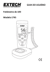
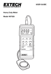
USER GUIDE LED Light Meter Model LT45 Introduction Congratulations on your purchase of the Extech LT45 LED Light Meter that measures light from LED lamps in addition to fluorescent, metal halide, high‐pressure sodium and incandescent sources. The LT45 is capable of measuring the illumination of white, red, yellow, green, blue, and purple LEDs up to 400,000 Lux (40,000 Fc). The LT45 can also calculate luminous intensity (CD) using a distance‐to‐the‐light value programmed by the user in meters or feet units. The LT45 can store up to 99 readings for later recall and includes Overload indication, Battery status icon, Data hold, Maximum/Average/Minimum (MAX/MIN) tracking, push‐button Zero calibration adjustment, Auto Power off (with disable function), and auto ranging features. This instrument is shipped fully tested and calibrated and, with proper use, will provide years of reliable service. Please visit our website (www.extech.com) to check for the latest version of this User Guide, Product Updates, and Customer Support. Features Overload Indication: LCD screen will show “OL” at the upper left‐hand corner Battery strength status indication Display Update Rate: 2.5 times per second Spectral response near CIE luminous spectral efficiency ratings Cosine Angle corrected Conforms to JIS C 1609:1993 and CNS 5119 general class A Specifications Measures the intensity of illumination of white, red, yellow, green, blue, and purple LED light and all visible light in Lux or foot‐candles Calculates Luminous Intensity (CD) Data hold freezes displayed reading Maximum/Average/Minimum Memory Hold Zero adjustment Auto power off with disable function Automatic range adjust optimizes accuracy and resolution Manually store/recall up to 99 readings Complete with light sensor, protective sensor cover, and coiled cable expandable to 59” (1.5m), 9V battery, and hard shell case 2 LT45-en-EU_V1.5 9/14 Safety Do not operate the meter in environments where the following are present: explosive gases (or materials), combustible gases (or materials), steam, or dust. Please replace the battery immediately when the battery symbol Do not touch the meter’s circuit board for any reason as static electricity or contamination could damage the sensitive components. For Indoor use only. This instrument was designed for pollution degree 2. Operation Altitude: Up to 2000m (7000’). appears on the LCD. Meter Description 1. Display (LCD) 2. Lux/Fc/CD unit select button 3. MEM/READ button (for 99 reading memory) 4. Up arrow button and MAX/MIN/AVG button 5. Power and Auto Power OFF control button 6. Zero Calibration button 7. Data Hold and Light source select button 8. Down arrow button 9. Coiled sensor connection cable 10. Photo detector Note: The battery and tripod mount are located on the back of the meter 3 LT45-en-EU_V1.5 9/14 Operation Power ON‐OFF Momentarily press the Power button to power the meter. To power the meter OFF, momentarily press the Power button again. Taking Measurements 1. Switch the meter ON 2. Remove the sensor’s protective cover to expose the light sensor dome. The display should switch ON, if not check that fresh batteries are installed. 3. The meter measures the intensity of the light (illuminance) that strikes the sensor dome in foot candles and lux units (1 fc = 10.76 lux) displaying the measured value on the LCD. 4. Use the LUX/FC/CD button to select Lux or Foot candle units (CD, luminous intensity, is explained in the dedicated section ‘Luminous Intensity’). When ‘OL’ is displayed, the measurement exceeds the meter’s range capability. 5. Position the meter and light source so that the light strikes the sensor dome perpendicularly. Although the meter compensates for an incidence angle, optimum performance is achieved with a smaller incidence angle. 6. The meter’s LCD can show a value up to 3999 on the large digits and when more digits are needed to represent the reading two additional (smaller) digits appear to the right of the larger digits, e.g. 399900. LUX/FC/CD Units Momentary presses of the LUX/FC/CD button toggles Lux and FC (foot‐candles) units. Press and hold the button to enter the CD (luminous intensity) mode. Refer to ‘Luminous Intensity’ section for further information. Auto Power OFF To save battery life the meter powers down automatically after approximately 5 minutes of inactivity (no button presses). Enable/Disable Auto Power Off With the meter ON, press and hold the Power button until the APO clock symbol switches OFF (the Auto Power OFF utility is now disabled and the user must manually switch the meter off). To re‐enable the Auto Power OFF utility, repeat this process. The Clock symbol will switch ON when the Auto Power OFF utility is re‐enabled. Zero Calibration 1. Ensure that the protective cover is attached to the light sensor. 2. Power the meter and the LCD should display ‘0’. 3. Momenarily press the “ZERO” button and the ADJ (adjusting) icon will switch ON indicating that the zero adjustment (calibration) is working. When the calibration is finished, the ADJ icon will switch OFF and the meter will return to the normal operating mode. 4. If the protective cap is not covering the sensor when the ZERO calibration is started the LCD display will read “CAP”. In this case, please cover the sensor with the cap and restart this procedure. 4 LT45-en-EU_V1.5 9/14 MAX/AVG/MIN Memory Mode The meter can record the maximum, minimum, and average readings as described below: button and the meter will begin to track the 1. Momentarily press the MAX/AVG/MIN maximum/average/minimum measurements; the “MIN” icon will display on the LCD indicating that the meter is now displaying the minimum reading. The reading will not change until a lower reading is registered. button again to switch from “MIN” to “MAX” where the meter will show the 2. Press the maximum measurement value. The “MAX” icon will be displayed on the LCD. button again to change the mode from “MAX” to “AVG”, where the meter will 3. Press the button was first pressed. The “AVG” show the average of the readings taken since the icon will be displayed. 4. Press the button again to switch from “AVG” back to “MIN”. To exit this mode, press and hold the button for at least 2 seconds. The MAX/AVG/MIN icons should all be switched OFF when the unit returns to the normal operating mode. Memory Record/Read Mode 1. Momentarily press the Mem/Read button to store a reading. The LCD will display a small ‘M’ icon on the lower left‐hand area of the LCD along with the memory location number (1 to 99) representing the storage location for the recorded reading. Up to 99 readings can be stored. 2. To review (read) the stored readings, press and hold the Mem/Read button until the ‘MEM’ icon appears at the top of the LCD. Now use the arrow buttons to scroll through the stored readings. The small ‘M’ icon and the memory location counter (1 to 99) will be shown on the lower left‐hand corner of the LCD while the main display digits show the stored reading for the selected memory location. 3. To store an average (AVG) reading, first access the AVG mode (See MIN/MAX/AVG section of this guide) and while an average reading is displaying (AVG icon switched ON), momentarily press the Mem/Read button for one second. The LCD will display ‘AVG M’ and the memory location number (1 to 99) indicating that an average reading has been stored in the numbered memory location. 4. When a stored reading is an AVG value, the screen will display ‘AVG’ on the lower left‐hand corner. 5. Momentarily press the Mem/Read button to exit the Memory mode and return to the normal operating mode. 6. To clear all 99 memory locations: With the meter switched OFF, press and hold the Mem/Read and On/Off buttons simultaneously for two seconds. The meter will switch ON and the screen will display “CLr” indicating that all of the 99 memory locations have been erased. Data Hold Press the Hold button to freeze the displayed reading (the ‘HOLD’ icon will switch ON). Press the button again to release the held reading (the ‘HOLD’ icon will switch OFF). 5 LT45-en-EU_V1.5 9/14 Luminous Intensity (CD) Measurements 1. Press the On/Off button to turn power ON. 2. Press and hold the LX/FC/CD button until the meter’s unit designator switches to CD. 3. Use the arrow buttons to select ft (feet) or m (meter) units to represent the distance the sensor will be from the light source. 4. Momentarily press the LX/FC/CD button; the smaller digits (lower‐right hand corner of LCD) will switch ON, these digits represent the distance to the light source. 5. Use the arrow buttons to set the distance from the center of the lamp to the measurement base level. Press and hold an arrow button to scroll quickly. 6. Momentarily press the LX/FC/CD button. 7. Remove the protective sensor cap and place the sensor perpendicular to the light at the programmed distance. 8. Read the Luminous Intensity calculation on the meter’s LCD display. 9. Press and hold the LX/FC/CD button to exit this mode. Luminous Intensity = illumination (Lx) x distance (ft2 or m2) The programmable distance range is 0.01 ~ 30.47 m (0.01 ~ 99.99 ft.) Light Source (L.S.) Selection There are 10 light source selections (L0 – L9) each having a unique calibration correction factor (multiplier). See the Light Source Factors list below. The multipliers for locations L0 through L6 are fixed for the lighting types listed. Locations L7 through L9 are extra locations that the user can customize (with a multiplier from 0.001 to 1.999). To change the light source (L.S.) selection: 1. Press and hold the Hold/LS button for 2 seconds. The light source code, at the bottom center of the LCD, will flash. Use the arrow buttons to select L0 through L9. The location’s multiplier (correction factor) will be shown to the right of the Lx value (L8…1000, for example). 2. To customize a location, select L7, L8 or L9 and, once selected, momentarily press the Hold/LS button to enter the multiplier programming mode. Now use the arrow keys to change the multiplier. Press and hold an arrow button to scroll faster. 3. When finished, press and hold the Hold/LS button for at least 1 second to confirm the edit and exit this mode. Light Source Factors L0: Standard light source: 1.00. L1: LED white daylight: 0.99. L2: LED RED light: 0.516. L3: LED AMBER (YELLOW) light: 0.815. L4: LED GREEN light: 1.216. L5: LED BLUE light: 1.475. L6: LED PURPLE light: 1.148. L7~L9: Programmable User Custom Locations (preset to 1.00) 6 LT45-en-EU_V1.5 9/14 Measurement Considerations and User Tips For maximum accuracy allow the light being measured to fall directly on the sensor as perpendicular as possible with a minimal angle of incidence. When the meter is not in use, please keep the protective cap in place, covering the light sensor. This will prolong the life of the sensor. When the meter is to be stored for long periods, please remove the battery and store it separately. Batteries can leak and cause damage to the meter’s components. Avoid areas of high temperature and humidity when using this instrument. Battery Replacement and Maintenance Cleaning and storage 1. The white plastic sensor dome should be cleaned with a damp cloth when necessary. Use only a mild soap if needed. Do not use solvents, abrasives, or harsh detergents to clean the dome. 2. Store the meter in an area with moderate temperature and relative humidity. Battery Replacement When the battery power decreases to a critical level, the battery symbol will appear as empty on the LCD. Replace the 9V battery located in the rear battery compartment. The battery compartment slides easily downward for removal (in the direction of the printed arrow on the rear of the meter). Ensure that the compartment cover is securely fastened before using the meter. Never dispose of used batteries or rechargeable batteries in household waste. As consumers, users are legally required to take used batteries to appropriate collection sites, the retail store where the batteries were purchased, or wherever batteries are sold. Disposal: Do not dispose of this instrument in household waste. The user is obligated to take end‐of‐life devices to a designated collection point for the disposal of electrical and electronic equipment. Battery Safety Reminders o Please dispose of batteries responsibly; observe local, state, national regulations. o Never dispose of batteries in a fire; batteries may explode or leak. 7 LT45-en-EU_V1.5 9/14 Specifications Sampling rate 2.5 times per second (digital display) Display 6‐digit LCD with battery icon, measurement overload, and other function indicators Sensor (detector) Silicon photodiode with spectral response filter and cosine correction Ranges and Resolution Lux: 399.9, 3999, *39999, *399999 Foot‐candles: 39.99, 399.9, 3999, *39999 *Above 3999, the LCD uses smaller digits on the right side (1 Fc = 10.76 Lux) Auto‐range The meter automatically ranges the display Accuracy ± (3% of reading + 3 digits) up to 500 Lux ± (3%) above 500 Lux o Calibrated to standard incandescent lamp 2856 K at an o ambient temperature of 23 C ±6% + 3 digits for other visible light sources ○ Angle deviation from cosine characteristics 30 ±2% ○ ±6% ○ ±25% 60 80 LED Types Operating conditions Storage Temperature/RH Battery status indication Power supply Auto Power OFF Dimensions Weight Meter measures white, red, yellow, green, blue, purple LED light o o Temperature: 5 to 40 C (41 to 104 F); Humidity: < 80% RH o o ‐10 to 60 C (14 to 140 F); Humidity: < 70% RH Battery symbol appears empty when battery voltage reaches critical level 9V battery Meter powers down after 5 minutes of inactivity (can be defeated) Meter: 38 x 55 x 130mm (1.5 x 2.2 x 5.1”) Sensor: 25 x 44 x 80mm (9.8 x 2.2 x 3.1”) Cable length: 1.5m (4.9 ft.) Approx. 250g (8.8 oz.) with battery installed 8 LT45-en-EU_V1.5 9/14 Appendix Typical Light Levels Lux 20‐75 75‐150 Foot Candles 2‐7 7‐15 150‐300 15‐30 300‐750 750‐1,500 1,500‐3,000 75‐100 100‐200 30‐75 75‐150 150‐300 7‐10 10‐20 200‐750 20‐75 Lux Factories Emergency Stairs, Warehouse Exit/Entrance Passages 100‐150 150‐200 Packing Work 200‐300 Visual Work: Production Line Typesetting: Inspection Work Electronic Assembly, Drafting Office Indoor Emergency Stairs Corridor Stairs 300‐500 500‐1,500 1,000‐2,000 75‐150 150‐300 Conference, Reception Room 750‐1,500 75‐150 Clerical Work 1,500‐2,000 150‐2000 Typing, Drafting Store 75‐150 7‐15 Indoors 150‐200 15‐20 Corridor/Stairs 200‐300 20‐30 Reception 300‐500 500‐750 750‐1,500 1,500‐3,000 300‐750 750‐1,500 30‐75 75‐100 100‐150 30‐50 50‐75 75‐150 Display Stand Elevator Show Window, Packing Table 150‐300 Storefront, Show Window 150‐200 200‐750 750‐1,500 5,000‐10,000 Foot Candles 10‐15 15‐20 Home Washing Recreational Activities 20‐30 Drawing Room, Table 30‐50 Makeup 50‐150 Reading, Study 100‐200 Sewing Restaurant 7‐15 Corridor Stairs 15‐30 Entrance, Wash Room 30‐75 Cooking Room, Dining Table 75‐150 Show Window Hospital 3‐7 Emergency Stairs 7‐10 Stairs 10‐15 Sick Room, Warehouse 15‐20 Waiting Room 20‐75 Medical Exam Room 75‐150 Operating Room 500‐1000 Eye Inspection Spectral Sensitivity Peak sensitivity wavelength: 550nm RELATIVE SENSITIVITY (%) LT45 WAVELENGTH (nm) Copyright © 2014 FLIR Systems, Inc. All rights reserved including the right of reproduction in whole or in part in any form www.extech.com 9 LT45-en-EU_V1.5 9/14