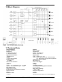
1
PSI Audio R&B 8A
Router and Bass-management
User Manual & Technical Datasheet
Functions
-
Easy switching between 3 Monitoring systems
Use of one multichannel speakers system in multichannel, satellite+sub or stereo modes
Subwoofer usable as bass extension or LFE
Standby/Mute and switching modes controlled by an standard double footswitch
Standby control for the unused PSI Audio speakers
Key features
-
Full analog transparent system without internal channels mixing
Integrated into the subwoofer PSI Audio A225-M as an option
Optional display providing standby and preparation modes
True balanced outputs adapted for balanced or unbalanced inputs
Internal input gains adjustments
Compatible with any monitors brand.
UANPA10 V3.1
PSI Audio R&B - User Manual
1
TABLE OF CONTENTS
1
INTRODUCTION................................................................................................................................................. 3
2
SAFETY INSTRUCTION.................................................................................................................................... 3
2.1
2.2
3
WARNINGS ....................................................................................................................................................... 3
SERVICE............................................................................................................................................................ 4
GENERAL OVERVIEW ..................................................................................................................................... 4
3.1
BEFORE YOU START .......................................................................................................................................... 4
4
QUICK START..................................................................................................................................................... 5
5
OPERATION ........................................................................................................................................................ 6
5.1
5.2
5.3
5.4
6
AUDIO SIGNAL INPUT CONNECTOR .................................................................................................................. 6
FOOTSWITCH .................................................................................................................................................... 6
ROLL-OFF ......................................................................................................................................................... 6
GLOBAL GAIN ................................................................................................................................................... 6
SETTINGS............................................................................................................................................................. 7
6.1
FACTORY SETTINGS .......................................................................................................................................... 7
6.2
PSC (PHANTOM STANDBY CONTROL).............................................................................................................. 7
6.3
HI-LFE UPMIX ................................................................................................................................................. 8
6.4
PREPARATION C USED ...................................................................................................................................... 8
THE C PREPARATION IS ACTIVATED BY THE SECOND (RIGHT) FOOTSWITCH. ACTIVATING THE FOOTSWITCH ENABLES
YOU TO SWITCH SUCCESSIVELY BETWEEN A, B AND C PREPARATION, THEN BACK TO A, B… AND SO FORTH. ........... 8
FOR AB COMPARISONS, THE SWITCH 8 “PREP. C USED” WILL BE OFF. ....................................................................... 8
6.5
PREPARATION A : 1...8 VIA 1...8 (SYSTEM 7.1)................................................................................................. 8
6.6
PREPARATION B : 1,2 (L+R) VIA 1,2, 4 (SAT+SUB) .......................................................................................... 8
6.7
PREPARATION C : 1,2 (L+R) VIA 7,8 (LIII AND RIII)....................................................................................... 8
7
POSSIBLE ADAPTATIONS BY A QUALIFIED TECHNICIAN .................................................................. 8
7.1
7.2
7.3
INTRODUCTION ................................................................................................................................................. 8
CONFIGURATIONS ............................................................................................................................................. 8
USUAL CONFIGURATIONS ................................................................................................................................. 9
8
C.E. & ROHS CONFORMITIES...................................................................................................................... 10
9
WARRANTY....................................................................................................................................................... 10
10
BLOCK DIAGRAM ........................................................................................................................................... 11
11
TECHNICAL DATA .......................................................................................................................................... 11
UANPA10 V3.1
PSI Audio R&B - User Manual
2
1 Introduction
Thank you very much, and congratulations on your decision to purchase a professional Router and Bassmangement (R&B) system from PSI Audio. The R&B, here after called “device”, can be either integrated
into a subwoofer PSI Audio sub A225-M or available as a stand-alone product. The following instructions
can be applied for both products.
Following carefully the instructions in this manual will ensure that your device will give you many years of
reliable and trouble free operation.
For the latest information, help or advice, please contact your local PSI Audio representative or PSI Audio
directly.
Relec S.A.
Rue des Petits Champs 11 a+b
CH-1400 YVERDON (Switzerland)
Tel : +41 (0)24 426 0420
Tel : +41 (0)24 426 0451
E
[email protected]
W
www.psiaudio.com
2 Safety Instruction
This symbol alerts the user to the presence of electrical
power within the product that may be of sufficient
magnitude to constitute a risk of electric shock.
This symbol alerts the user to important operating and
maintenance (servicing) instructions or warnings.
2.1
Warnings
•
Please read and follow the instructions of this manual carefully before using your system.
•
Please do not open the device - risk of electric shock inside.
•
Make sure not to expose the device to any form of liquids. For cleaning purposes use only a dry
cloth. In order to prevent spills, do not place any containers containing liquid on the device. Do not
use the device close to water as this may create a shock hazard.
•
Check your AC voltage and make sure that the voltage setting and fuse on the rear of the chassis
are set correctly.
•
Do not operate the device in a confined environment (i.e. in a flight case) The rear panel of the
speaker must not be covered and permit appropriate circulation and ventilation of air for cooling
purposes. Make sure all ventilation openings are free of any obstacles.
•
Do not operate or install this device near any kind of heat source.
UANPA10 V3.1
PSI Audio R&B - User Manual
3
2.2
Service
The device contains no user-serviceable parts. All service must be performed by
qualified personnel. The primary fuse must be replaced by exactly the same type and
rating. The unit must not be opened by the user – risk of a severe electric shock. The
device can be configured for many applications. Factory settings are related to most
common uses of the device.
Servicing is required when:
• changing the factory settings
• the device has been damaged in some way, such as when the power-supply cord or plug is
damaged.
• the device has suffered from exposure to rain or moisture
• liquid has been spilled into the device.
• objects have been dropped into the device
• the device does not work correctly.
Spare part supply:
•
For ordering, please contact your authorized dealer, mentioning your device/loudspeaker
model and serial number (see point 3.3.).
3 General Overview
3.1
Before you start
Special care have been taken in the packaging of your PSI Audio equipment. Before you start to
install it, please check that the following parts are included:
- If the R&B device is originally mounted into a subwoofer, you shall also get in the package:
• PSI AUDIO R&B User Manual (this manual)
- If the R&B device is delivered to be integrated into a subwoofer, you shall also get in the package:
• PSI AUDIO R&B User Manual (this manual)
• 3 separate power supply cables to connect the R&B PCB to the subwoofer.
• 1 sticker A6 with the Factory settings that you can stick inside the amplifier chamber of your
subwoofer as a reminder.
UANPA10 V3.1
PSI Audio R&B - User Manual
4
4 Quick Start
We recommend that you spend some time to set up your monitoring speaker system with your Router
and Bass-management system.
Setting it up naturally takes a certain amount of time. However, in case you need to get started quickly,
please follow the quick set up guide. The rest of this manual will assist you in setting up your loudspeaker
system and calibrate it according to your listening environment.
• Check that the voltage value on the AC power selector is set correctly (according to your local AC
power supply). If this is not the case, it will be necessary to adjust main power with the following
procedure. Carefully squeeze the two latches on either side of the fuse plug and pull the fuse
holder out of its socket. Now replace the fuse for the different voltage setting with the correct value
fuse according to the required voltage. The correct value of the fuse is printed next to the On-Off
switch of your device. Pull out the grey plastic cap which holds the fuse and turn it 180° so it shows
the correct voltage setting through the outer window when placed back in its position. Now you can
carefully push the complete fuse holder back in to its place above the mains connector.
• Connect the audio source(s) (line signal) from your mixer, preamplifier or other equipment to the
XLR connector input.
• Control the compatibility of the PSI Audio R&B with your monitors. If you use monitors of the PSI
Audio M series, a standby phantom voltage (PSC – phantom standby control) is provided by the
R&B. This voltage is immediately stopped when you switch on the remote dual footswitch. If some
monitors do not feature the PSC technology, your router can be configured accordingly by a
qualified technician without any additional device. Your router is therefore compatible with the vast
majority of audio monitors of the market.
• Verify that the Roll-Off potentiometers of the satellite monitor and of the Router are in a factory
settings configuration. The Roll-off of the satellite monitor is turned fully clockwise in order to
provide a flat frequency response to start with. The Roll-off of the R&B device is turned fully
counter-clockwise.
• Connect the mains cable with power whilst paying attention to the warnings mentioned under the
chapter safety instructions.
• Verify that no audio signal is been sent to the device and turn the power switch to ON. The green
led on the front panel will now illuminate.
• If you work with the Satellite + Subwoofer listening mode, the roll-off must be adjusted to get the
right tonal balance with or without the subwoofer. This also implies a right placement of the
subwoofer as well as a calibration of the level of the subwoofer.
Please refer to the User Manual of the subwoofer “chapter 6. Installation p. 7 to 11” for more detail
about the subwoofer calibration.
When you switch on the device with the factory settings, the R&B is in A preparation mode.
You can mute your system when you press on the first (left) button of your remote footswitch.
UANPA10 V3.1
PSI Audio R&B - User Manual
5
5 Operation
5.1
Audio Signal Input Connector
The female XLR connector on the rear panel provides a balanced analog input with the following
wiring conventions :
1 = Chassis (Ground)
2 = + Hot
3 = - Cold
When using the device with unbalanced sources, the following wiring conventions may be used
Cable
XLR
1
2
3
RCA/ Chinch
5.2
Shield/Screen
Footswitch
The first button (left) of the remote dual footswitch enables to command the standby function of the
R&B and of the Monitors according to the configuration of the factory settings. The A, B and C
preparations determine how to route the inputs to the outputs of the R&B and the bass-management.
The configuration determines if each monitor is compatible with the Phantom Standby Control (PSC)
technology. It also determines the function of the Hi-LFE upmix, as well as the C preparation.
5.3
Roll-off
The roll-off potentiometer enables to decrease the low frequencies of the monitors for a
Satellite+Subwoofer preparation. The roll-off is not active for other types of preparations.
The calibration of the sub level should be done by comparing a stereo preparation with a satellite +
subwoofer preparation. The signal used for the calibration should contain low frequencies (about
70Hz – lows of a cello). Adjust the level of the subwoofer, then the Roll off of the R&B so that you get
the same tonal balance on both preparation (with and without the subwoofer). This calibration is also
valid for the use of the subwoofer as an LFE in a surround system.
5.4
Global gain
The global gain is usually set at 0dB (LFE +10dB). In case of weaker signals (non-professional
systems), the input gains can be recalibrated by a qualified technician.
UANPA10 V3.1
PSI Audio R&B - User Manual
6
6 Settings
6.1
Factory settings
The following settings can all be adapted by a qualified technician (see chapter 7).
The factory settings set the global gain at 0dB. The roll-off are set at -10dB.
Here is the procedure to integrate the R&B board into the subwoofer:
1) Lay the subwoofer on the side and make sure the power cable is not connected.
2) Open the 3 screws of the left side of the subwoofer amplifier board and open the back panel like
a door.
3) Remove the blank cover at the back of your subwoofer (this blank panel made to integrate the
R&B board only exists from the PSI Audio subwoofer A225-M V5. Please contact us at
[email protected] if you own an older version to get a quote for an upgrade).
4) Stick the A6 sticker labelled “Factory Settings” inside the amplifier chamber of your subwoofer as
a help and reminder.
5) Install the R&B board and screw the right side of the board
6) Before you screw the panels on the subwoofer, interconnect the R&B board to the subwoofer
with the 3 power supply cables. There are three slots, make sure to connect the power supply
cable with the black connector (ground) in the centre slot. The other two (+V2 and –V2) shall be
indifferently placed of both sides of it.
7) You can now configure your R&B board according to your needs (see chapter 7 here below)
8) Screw your R&B and your subwoofer board. The installation of the R&B board is now done, you
are now ready to interconnect your source to the device and then from your device to your
speakers.
6.2
PSC (Phantom Standby Control)
The PSC is activated for outputs 1 to 6 and allows to put the unused channel in standby mode with
PSC equipped monitors.
PSC are not activated for outputs 7 and 8, in order to switch on a Monitor system that does not
feature the PSC technology.
UANPA10 V3.1
PSI Audio R&B - User Manual
7
6.3
Hi-LFE Upmix
If by accident, the LFE signal contains frequencies above 120Hz, those frequencies would be
reduced by 6dB and reinjected in the outputs 1 and 2 to be easily detected.
6.4
Preparation C used
The C preparation is activated by the second (right) footswitch. Activating the footswitch enables you
to switch successively between A, B and C preparation, then back to A, B… and so forth.
For AB comparisons, the Switch 8 “prep. C used” will be OFF.
6.5
Preparation A : 1...8 via 1...8 (system 7.1)
This listening mode is adapted for multichannel monitoring 5.1 and 7.1. The inputs 1, 2, 3 and 5, 6, 7,
8 via 1, 2, 3 and 5, 6, 7, 8 without modifications. The input 4 (LFE) is amplified by 10dB via output 4.
At the same time, it is reduced by 6dB with a high-pass at 120Hz and remixed via output 1 and 2.
6.6
Preparation B : 1,2 (L+R) via 1,2, 4 (sat+sub)
This system is particularly efficient when space is an issue and high SPL are required for recording.
Low frequencies of inputs 1 and 2 are reduced by the “Roll off”, the signal is directed respectively via
output 1 and 2. The sum of the channel 1 and 2 are sent via output 4, the PSI sub A225 makes the
complementary response from 24Hz.
6.7
Preparation C : 1,2 (L+R) via 7,8 (LIII and RIII)
This system enables to compare a third system. The inputs 1 and 2 are directed respectively via
output 7 and 8 without changes.
7 Possible adaptations by a qualified technician
7.1
Introduction
For all changes of configuration, such as configuration changes, the power cable must be
disconnected.
Unscrew the two screws on the left side of the R&B seen from the serigraphy back panel. The back
panel opens likes a door and should not be opened more than the 90° right angle.
At the centre on the low part of the PCB are 4 groups of 8 switches
- The superior group manages the configurations
- The second group manages the preparation A
- The third group manages the preparation B
- The forth group manages the preparation C
7.2
Configurations
Switch 1 = ON
A voltage of 5V is active at the outputs 1 and 2 for mute for the monitors that feature the PSC
technology. If the monitors do not feature PSC technology, the Switch 1 = OFF
Switch 2 = ON
Same for output 3
Switch 3 = ON
Same for output 4
Switch 4 = ON
Same for outputs 5 and 6
Switch 5 = ON
Same for outputs 7 and 8
UANPA10 V3.1
PSI Audio R&B - User Manual
8
Switch 6 = ON
The monitors unused will automatically turn in standby mode (red LED).
If the monitors must always to be always be on (green LED) the switch 6 = OFF
Switch 7 = ON
On Multichannel recordings, high frequencies on the input 4 (LFE) must absolutely be avoided. For
controlling, in order to be sure that those frequencies could be heard, all the frequencies above
120Hz are reduced by 6dB and remixed in the outputs 1 and 2. If all channels must be independent,
the switch 7 = OFF.
Switch 8 = ON
The R&B enables to switch successively between preparations A, B and C. To restrict the
comparisons to AB only, the switch 8 = OFF
7.3
Usual configurations
Important notice : when the R&B is integrated into the PSI Audio A225-M, the XLR output 4 of the R&B board
must be connected to the XLR input of the A225-M with a short balanced cable.
UANPA10 V3.1
PSI Audio R&B - User Manual
9
8 C.E. & RoHS Conformities
Beyond the tests of all components, the PSI Audio products have been tested and calibrated according to
the highest quality standards.
The PSI Audio products have been tested according to EU directives and amendments:
Low voltage directive (LVD), 2006/95/EC
Electromagnetic compatibility directive (EMC), 2004/108/EC
The relevant technical standards are:
EN 60065:
1998 Audio, video and similar apparatus – Safety requirements (Class 1)
EN 55103-1/E1:
1996 Product Standard – Emission
Audio, Video and audio-visual apparatus for professional use
EN 55103-2/E1:
1996 Product Standard – Immunity
Audio, Video and audio-visual apparatus for professional use
This product is manufactured according to the European directive 2002/95/EC
9 Warranty
Our products are guaranteed during 2 years against any manufacturing defect. Fair or wrong wear and
tear are not covered by the warranty. We kindly remind the user that unauthorised servicing can void the
warranty. In order to provide a quality service, we ask the user to always join the warranty card for each
servicing.
For servicing, the expenses and the risks of transport are the responsibility of the customer.
For any other provision, the Swiss Code of Obligations, Articles 197 to 210 will apply.
For any legal action, reference will apply to the Court of Yverdon (Switzerland) only.
UANPA10 V3.1
PSI Audio R&B - User Manual
10
10 Block Diagram
11 Technical Data
Input Impedance:
8 x Sym, 10kOhms
Response:
± 0.1dB (20Hz-20kHz)
± 1 dB (5Hz-100kHz)
Signal to Noise Ratio:
-96 dBu pond A
CMRR:
> -55 dB (20Hz-20kHz)
Dynamic range:
> 118 dBA
Interchannel isolation:
> 90 dBA
Gain:
Inputs 1..3,5..8 : 0dB intern. adj. -2..+12dB
Inputs 4 : 0/+10dB intern. adj. -2..+12dB
Max Output Level:
28Vpp <0.001% THD
if PSC used: 5V DC Phantom in standby
Input Overload:
24 Vpp
Distortion THD:
<0.001%
UANPA10 V3.1
System:
8 IN => 8 OUT
Connectors:
IN/OUT XLR Balanced
Remote Jack 6.35 3p
Signal input:
XLR : 1=GND, 2=(+), 3=(-)
JACK : Ring : GND=Power ON, OPEN=Standby
Tip : GND,OPEN change=Next Preparation
Dimensions W x H x D mm:
280 x 220 x 60
Gross / Net Weight:
0.95 kg
Voltage:
115/230V (50-60Hz)
Consumption Standby-Quiescent-Max:
1.4 - 14 - 20 W
Mean / Max Humidity:
< 75% / < 90%
External Temperature:
5 - 40°C
Remote:
Standard dual foot switch (ex: FS-202 Stageline)
PSI Audio R&B - User Manual
11
UANPA10 V3.1
PSI Audio R&B - User Manual
12