1
Cat. No. W414-E1-01
SYSMAC
SYSMAC
WS02-CXPC1-EV3
CX-Programmer Ver.3.1
Operation Manual
Revised November 2002
OMRON
CX-Programmer – Operation Manual
About this Manual (W414):
This manual describes the operation of the CX-Programmer and consists of the following three parts.
•
Part 1: CX-Programmer
This part describes the CX-Programmer software that is a PLC
Programming Device, and also provides the overall precautions and the
version upgrades information.
•
Part 2: CX-Server PLC Tools
This part describes the CX-Server PLC Tools software, which is a
collection of the following components:
PLC Memory, IO Table, PLC Setup, Data Trace/Time Chart Monitor, PLC
Error, Memory Card, PLC-Clock, and CX-Net Network Configuration.
(including Data Link Editor and Routing Table)
•
Part 3: CX-Server Runtime
This part describes the CX-Server software that is a communications
middleware.
Note: References within each part are references to the pages or chapters within that part.
CX-Programmer
PART1:
CX-Programmer
OMRON
PART1: CX-Programmer
Notice
OMRON products are manufactured for use according to proper procedures by a qualified operator and
only for the purposes described in this manual.
The following conventions are used to indicate and classify precautions in this manual. Always heed the
information provided in them. Failure to heed precautions can result in injury to people or damage to the
product.
DANGER! Indicates information that, if not heeded, is likely to result in loss of life or
serious injury.
WARNING Indicates information that, if not heeded, could possibly result in loss of life or
serious injury.
Caution
Indicates information that, if not heeded, could result in relatively serious or
minor injury, damage to the product, or faulty operation.
OMRON Product References
All OMRON products are capitalised in this manual. The word “Unit” is also capitalised when it refers to
an OMRON product, regardless of whether or not it appears in the proper name of the product.
The abbreviation “PLC” means Programmable Logic Controller and is not used as an abbreviation for
anything else.
CX-Programmer_Page (i)
OMRON
PART1: CX-Programmer
Visual Aids
The following headings appear in the left column of the manual to help you locate different types of
information.
Indicates information of particular interest for efficient and convenient operation of the product.
1, 2, 3…
Indicates lists of one sort or another, such as procedures, checklists etc.
Represents a shortcut on the Toolbar to one of the options available on the menu of the same
window.
OMRON Electronics LLC 2002-2003
All rights reserved. No part of this publication may be reproduced, stored in a retrieval system, or
transmitted, in any form, or by any means, mechanical, electronic, photocopying, recording, or otherwise,
without the prior written permission of OMRON.
All copyright and trademarks acknowledged.
No patent liability is assumed with respect to the use of the information contained herein. Moreover,
because OMRON is constantly striving to improve its high-quality products, the information contained in
this manual is subject to change without notice. Every precaution has been taken in the preparation of this
manual. Nevertheless, OMRON assumes no responsibility for errors or omissions. Neither is any liability
assumed for damages resulting from the use of the information contained in this publication.
CX-Programmer_Page (ii)
OMRON
PART1: CX-Programmer
About this Part
This part describes the CX-Programmer application and its ability to create and maintain programs for use
with OMRON SYSMAC CS, CV and C PLCs. It does not provide detailed information concerning the
PLCs themselves, for this information the commercial manual for the device must be consulted.
This part contains the following chapters:
•
Precautions. This portion describes general precautions for using the CX-Programmer (including
CX-Server PLC Tools).
•
Version Upgrade Information. This portion describes the changes that have been made from
version 3.0 to version 3.1 of the CX-Programmer.
•
Chapter 1 Introduction. This chapter describes the CX-Programmer software in general terms and
also provides details of the operating environment and minimum configuration necessary for the
satisfactory operation of CX-Programmer.
•
Chapter 2 Quick Start Guide. This chapter describes the basic features of CX-Programmer together
with a simple tutorial for fimiliarisation purposes.
•
Chapter 3 Project Referernce. This describes the features common to two or more parts of CXProgrammer.
•
Chapter 4 Reference. This chapter introduces the features contained in the Project workspace and
discusses their associated commands and features.
•
Chapter 5 Advanced Topics. This chapter discusses the more advanced topics in relation to CXProgrammer.
Appendix A Toolbars and Keyboard Shortcuts. This appendix summerises the toolbar and keyboard
shortcuts available from CX-Programmer.
A Glossary of Terms and Index are also provided.
•
CX-Programmer_Page (iii)
OMRON
PART1: CX-Programmer
Precautions
Intended Audience
This manual is intended for the following personnel, who must also have
knowledge of electrical systems (an electrical engineer or the equivalent).
• Personnel in charge of installing FA systems.
• Personnel in charge of designing FA systems.
• Personnel in charge of managing FA systems and facilities.
General Precautions
The user must operate the product according to the performance
specifications described in the operation manuals.
Please exercise particular care and consult your FA experts before using
the product under conditions which are not described in the manual or
applying the product to nuclear control systems, railroad systems, aviation
systems, vehicles, combustion systems, medical equipment, amusement
machines, safety equipment, and other systems, machines, and equipment
that may have a serious influence on lives and property if used improperly.
Make sure that the ratings and performance characteristics of the product
are sufficient for the systems, machines, and equipment, and be sure to
provide the systems, machines, and equipment with double safety
mechanisms.
This manual provides information for programming and operating the Unit.
Be sure to read this manual before attempting to use the Unit and keep this
manual close at hand for reference during operation.
WARNING
It is extremely important that a PLC and all PLC Units be used for the
specified purpose and under the specified conditions, especially in
applications that can directly or indirectly affect human life.
Safety Precautions
WARNING
Confirm safety sufficiently before transferring I/O memory area status from
the CX-Programmer to the PLC. The devices connected to Output Units
may malfunction, regardless of the operating mode of the CPU Unit.
Caution is required in respect to the following functions.
• Transferring from the CX-Programmer to real I/O (CIO Area) in the CPU
Unit using the PLC Memory window.
• Transferring from file memory to real I/O (CIO Area) in the CPU Unit
using the Memory Card window.
Caution
Confirm safety at the destination node before transferring a program to
another node or changing contents of the I/O memory area. Doing either of
these without confirming safety may result in injury.
Caution
Execute online edit only after confirming that no adverse effects will be
caused by extending the cycle time. Otherwise, the input signals may not
be readable.
CX-Programmer_Page (iv)
OMRON
PART1: CX-Programmer
Caution
Confirm safety sufficiently before monitoring power flow and present value
status in the Ladder Section window or when monitoring present values in
the Watch window. If force-set/reset or set/reset operations are
inadvertently performed by pressing short-cut keys, the devices connected
to Output Units may malfunction, regardless of the operating mode of the
CPU Unit.
Application Precaution
Observe the following precautions when using the CX-Programmer.
• Observe the following precautions before starting the CX-Programmer.
• Exit all applications not directly related to the CX-Programmer.
Particularly exit any software such as screen savers, virus checkers,
email or other communications software, and schedulers or other
applications that start up periodically or automatically.
• Disable sharing hard disks, printers, or other devices with other
computers on any network.
• With some notebook computers, the RS-232C port is allocated to a
modem or a infrared line by default. Following the instructions in
documentation for your computer and enable using the RS-232C port
as a normal serial port.
• With some notebook computers, the default settings for saving
energy do not supply the rated power to the RS-232C port. There
may be both Windows settings for saving energy, as well as setting
for specific computer utilities and BIOS. Following the instructions in
documentation for your computer, disable all energy saving settings.
• Do not turn OFF the power supply to the PLC or disconnect the
connecting cable while the CX-Programmer is online with the PLC. The
computer may malfunction.s
• With the CS/CJ-series PLCs, when creating an AUTOEXEC.IOM file
from the CX-Programmer to automatically transfer data at startup, set the
first write address to D20000 and be sure that the size of data written
does not exceed the size of the DM Area. When the data file is read from
the Memory Card at startup, data will be written in the CPU Unit starting
at D20000 even if another address was set when the AUTOEXEC.IOM
file was created. Also, if the DM Area is exceeded (which is possible
when the CX-Programmer is used), the remaining data will be written to
the EM Area. Refer to information on file operations in the CS/CJ-series
Programming Manual for details.
• Confirm that no adverse effect will occur in the system before attempting
any of the following. Not doing so may result in an unexpected operation.
Changing the operating mode of the PLC.
• Force-setting/force-resetting any bit in memory.
• Changing the present value of any word or any set value in memory.
• Check the user program for proper execution before actually running it
on the Unit. Not checking the program may result in an unexpected
operation.
• Precaution on Using Indirect DM and EM Addresses in Comparison
Instructions:
When indirect DM or EM addresses are used as operands in comparison
instructions, the top portion of the comparison instruction will be
displayed in yellow when it is being monitored. At that time the power
flow will not be monitored to the right of such comparison instructions.
The contact and coil status, and present values of operands in special
instructions will be displayed normally.
CX-Programmer_Page (v)
OMRON
PART1: CX-Programmer
• The user program and parameter area data in CS1-H CPU Units is
backed up in the built-in flash memory. The BKUP indicator will light on
the front of the CPU Unit when the backup operation is in progress. Do
not turn OFF the power supply to the CPU Unit when the BKUP indicator
is lit. The data will not be backed up if power is turned OFF.
To display the status of writing to flash memory on the CX-Programmer,
place a checkmark by Display dialog to show PLC Memory Backup
Status on the PLC properties and then select Windows | PLC Memory
Backup Status from the Windows menu.
• Precaution in Changing the PLC Type
On the CX-Programmer, you can change the PLC (device) type or CPU
type. When these are changed, however, only the data for the ladder
program and the symbol tables are changed. The following data will be
initialized and must be reset.
• PLC Setup
• Expansion instructions
• I/O tables
• PLC memory
Particularly the PLC Setup has a large impact on PLC system operation.
Be careful to reset all require settings after changing the PLC type.
If expansion instruction allocations are not reset, program errors could
occur, preventing the PLC from running. Always restore the expansion
instruction allocates to the previous settings after changing the PLC
type.
CX-Programmer_Page (vi)
OMRON
PART1: CX-Programmer
Observe the following precautions when using the CX-Net.
• Do not change the operating mode of the CPU Unit without first
confirming that operation of the controlled system will not be affect.
• Do not run the user program on the PLC until its operation has been
checked sufficiently.
• The data link mode (manual setting or automatic setting) and data link
method are determined according to the data link setting in the startup
node. In the startup node, set a data link table in the case of manual
setting and data link automatic setting parameters in the case of
automatic setting. If the settings are incorrect, the data link will not start.
• Check the following items before starting data links. If incorrect data link
tables or parameters are set, injury may result due to unexpected
operation of the system. Even if the correct data link tables and
parameters have been set, do not start or stop data links before verifying
that there will be no adverse influence on the system.
(1) Manually Set Data Links
Check the data link tables in each node participating in the data link to
see that they are correct.
Be sure that data link tables are deleted from nodes that are not
participating in the data links.
(2) Automatically Set Data Links
Be sure that the correct DM parameters have been set in the data link
startup node.
• CPU Bus Units will be automatically restarted when routing tables are
transferred from a Programming Device to the CPU Unit. Resetting is
required to use the new tables. Confirm that restarting the CPU Bus
Units will not adversely affect system operation before transferring
routing tables.
CX-Programmer_Page (vii)
OMRON
PART1: CX-Programmer
Version Upgrade Information
The following tables outline the changes that have been made from version 3.0 to version 3.1 of the CXProgrammer.
Q Program Editing Functions
Improvements to Global Reparacement Operation
Previous version (Ver. 3.0)
New version (Ver. 3.1)
Changes between normally open
contacts and normally closed contacts
could be performed only with the / key.
They could not be performed globally.
If Change All is selected from the Edit menu and a checkmark is placed in the
checkbox for Invert open/close bit before performing a global replacement for the
PLC, all specified operands that are normally open contacts will be changed to
normally closed contacts and all normally closed contacts will be changed to
normally open contacts. Refer to Chapter 3 of PART 1 for details (page 41).
Global replacements for addresses
applied to both the ladder programs and
symbol data.
If the check box for symbols (including I/O comments) is cleared before an
address is replaced globally, the symbols table and I/O comments will not be
changed and only addresses in the ladder program will be changed.
If the check box for symbols (including I/O comments) is selected before an
address is replaced globally, the replacement operation will be the same as the
previous version.
Drawing or Deleting a Connecting Line by Dragging from the Start Point to the End Point
Previous version (Ver. 3.0)
New version (Ver. 3.1)
Connecting lines could be input from the
keyboard, icons, or menus. (They could
not be input by dragging with the
mouse.)
Connecting lines can be drawn by clicking the Line Connect Mode icon and
then clicking the starting point and dragging to the end point. Connecting lines
can also be deleted by dragging after clicking the Line Delete Mode icon.
Note: A line can also be drawn by dragging on a line that is not connected on
one end. Refer to Chapter 3 of PART 1 for details (page 21).
Operand at the Cursor Position Appears as Default for Find or Replace Operations
Previous version (Ver. 3.0)
New version (Ver. 3.1)
When performing a Find or Replace
operation, the previous contents of the
previous Find and Replace fields are
displayed regardless of the position of
the cursor.
When a Find or Replace operation is performed, the Bit Addresses, Addresses,
Values, Symbol Names, or Mnemonics (i.e., in the Look at field for each) at the
position of the cursor is displayed in the Find what field. Refer to Chapter 3 of
PART 1 for details (page 38-39).
Note: If the Look at field is a Symbol comments or Program comments, the Find
what field will be blank.
History of Previous Find or Replace Settings
Previous version (Ver. 3.0)
New version (Ver. 3.1)
No history of previous settings was
displayed for Find or Replace operations.
Histories of previous find and replace settings are displayed in pull-down menus
for the Find what field and Replace with field. Refer to Chapter 3 of PART 1 for
details (page 38-39).
Size Changes for Go to Commented Rung Window
Previous version (Ver. 3.0)
New version (Ver. 3.1)
The size of the Go to Commented
Rung window was fixed when jumping to
rung comments. (This window was
previously a dialog box.)
The size of the Go to Commented Rung window displayed when Edit | Go to |
Commented Rung is selected can be changed. Refer to Chapter 3 of PART 1
for details (page 48).
CX-Programmer_Page (viii)
OMRON
PART1: CX-Programmer
Guidance Displays for SYSMAC Support Software or SYSWIN Shortcut Keys
Previous version (Ver. 3.0)
New version (Ver. 3.1)
Shortcut keys could be allocated for CXProgrammer functions for SYSMAC
Support Software operations and
SYSWIN operations, but guidance could
not be displayed.
Guidance can be displayed for CX-Programmer functions for SYSMAC Support
Software operations and SYSWIN operations by selecting Function Key
Guidance from the View menu. The CX-Programmer shortcut key allocations for
all keys can be displayed by selecting Information Window from the View
menu. Refer to Chapter 1 of PART 1 for details (page 5).
Q Online Functions
Q Monitor Functions
Display Form Setting for Operands for Special Instructions when Monitoring in Ladder
Section Windows
Previous version (Ver. 3.0)
New version (Ver. 3.1)
When monitoring on the Ladder Section
window, the symbol data type was given
priority as the display format for
operands for special instructions.
For example, the data type for the MOV
instruction is CHANNEL, so the display
was always 4-digit hexadecimal.
The data type for MOVL is also
CHANNEL so the display was always 8digit hexadecimal.
Also, for an unnamed symbol the data
type is CHANNEL so the display was
always 4-digit hexadecimal.
The display format for the present values of operands of special instructions
when monitoring on the Ladder Section Window can be selected from the
following data types. The same display format must be used globally.
To select the display format, click the desired button or select Monitoring Data
Type from the View menu.
• Decimal
• Signed Decimal
• Monitor in Hex
The default display formats will be as follows if none of the above display
formats is selected.
• Named symbol will be monitored in the symbol data type.
• Unnamed symbol will be monitored in the operand data type.
• Two-word operations, such as for the MOVL instruction, will be monitored in
2-word hexadecimal.
• For present values displayed in formats other than hexadecimal, “D” is
attached for 2-word data and “L” is attached for 4-word data. Refer to
Chapter 3 of PART 1 for details (page 74).
Improvement in Operation to Change PVs for Special Instructions
Previous version (Ver. 3.0)
New version (Ver. 3.1)
Present values were changed from the
menus.
Present values can be changed by pressing the Enter key on an operand that is
being monitored, or by double-clicking it.
Start Address Setting when Monitoring Present Values in I/O Memory
(Continuous Address Monitoring)
Previous version (Ver. 3.0)
New version (Ver. 3.1)
The address to monitor in the PLC
Memory Window could not be specified
(either the screen had to be scrolled or
individual addresses had to be monitored
in Watch windows).
Also, with floating-point or doubleprecision floating-point binary, monitoring
was possible only from addresses
divisible by 2 or 4.
The start address to be monitored can be specified to monitor consecutive
addresses in the PLC Memory Window. Refer to Chapter 2 of PART 2 for
details (page 10-11).
CX-Programmer_Page (ix)
OMRON
PART1: CX-Programmer
Monitoring Bit Status and Word Contents when Monitoring Present Values in I/O Memory
Previous version (Ver. 3.0)
New version (Ver. 3.1)
Bit status displays in the PLC Memory
Window had to be performed in word
units.
When the binary word display format is selected for the PLC Memory Window,
bit status is displayed both for individual bits and as hexadecimal word values.
Refer to Chapter 2 of PART 2 for details (page 10-11).
Simple Transfer of Data to the PLC when Monitoring Present Values in I/O Memory
Previous version (Ver. 3.0)
New version (Ver. 3.1)
To transfer data changed in I/O memory
while monitoring, the monitor status had
to be cleared and then PLC | Transfer |
To PLC had to be selected, the range
specified, and the transfer specified in
the PLC Memory Window.
Individual cells being monitoring in the PLC Memory Window can be selected
and the Set | Value command or the Set Value button can be used to display
the Set Present Value dialog box. Data can be input into this dialog box for
individual I/O memory address and then the OK button can be clicked to
directly change the value in the PLC.
When binary values are being displayed, the menus and buttons can be used to
Set, Reset, Force On, Force Off, or Force Cancel individual bits. Refer to
Chapter 2 of PART 2 for details (page 10).
Q Clear All Memory Areas Function
All Clear Operation for CPU Unit Memory (User Program, Parameter Area, and I/O Memory)
Previous version (Ver. 3.0)
New version (Ver. 3.1)
Unless a memory error actually occurred in the PLC
the CPU Unit memory clear operation (see note) could
not be performed from the Error Log. Also there was no
function (all clear) to initialize the CPU Unit memory.
Note: The CX-Programmer had to be placed online,
PLC | Edit Error Log had to be selected to display the
Errors window, and then the Clear All button had to be
clicked.
The user program, Parameter Area, and I/O Memory in the CPU
Unit can be cleared to initialize the CPU Unit by selecting Clear
All Memory Areas from the CX-Programmer's PLC menu or
selecting Clear All Memory Areas from the Options menu of
the PLC Errors dialog box.
These operations are possible even if a memory error has not
occurred in the PLC (the same as they are for a Programming
Console). Refer to Chapter 4 of PART 1 (page 78) and Refer to
Chapter 6 of PART 2 (page 10-11) for details.
Q On-line Editing
Power Flow Monitoring during Online Editing
Previous version (Ver. 3.0)
New version (Ver. 3.1)
The power flow could not be monitored
during online editing.
The power flow is displayed during online editing in monitoring status.
I/O Comment Changes during Online Editing
Previous version (Ver. 3.0)
New version (Ver. 3.1)
Changes to I/O comments made during
online editing could not be saved in the
CPU Unit (see note).
If changes were made, the symbol table
file had to be transferred to file memory
in a CS-, CJ-, CVM1, or CV-series PLC
or to the I/O comment area in UM (user
memory) in a C-series PLC.
Note: New I/O comments could be
added to the symbol table in CXProgrammer.
I/O comments can be changed during online editing in Ladder diagram view,
in the Symbol Table, or in I/O Comment View.
If I/O comments have been changed when online editing is ended, a
confirmation message will appear asking if the symbol table file should be
transferred to file memory in a CS-, CJ-, CVM1, or CV-series PLC or to the I/O
comment area in the allocated UM (user memory) in a C-series PLC.
Refer to Chapter 2 of PART 1 for details (page 24).
Note 1: Symbol table names and addresses cannot be changed during online
editing.
Note 2: I/O comments with symbol names cannot be transferred to the I/O
comment area in UM (User Memory) in C-series PLCs.
CX-Programmer_Page (x)
OMRON
PART1: CX-Programmer
Q Verification
Program Verification Offline or Online
Previous version (Ver. 3.0)
New version (Ver. 3.1)
Program verification was possible only
between the current project and the PLC.
Program verification is possible offline between the current project and a
closed project file. (Select Compare Program from the File menu and select
the file to be compared.) The results of verification can be saved to a file in
CSV format. Refer to Chapter 2 of PART 1 for details (page 23).
Added or omitted instructions were not
displayed in verification results (if added
or omitted instructions were
encountered, the verification results for
the rest of the program would show that
the programs were completely different).
Verification results are displayed by section and mnemonic, including added
or omitted instructions. Jumping is also possible from mnemonic verification
results to the corresponding locations in ladder view. Refer to Chapter 2 of
PART 1 for details (page 23).
Displaying Dialog Box for Verification or Transfer when Going Online
Previous version (Ver. 3.0)
New version (Ver. 3.1)
Nothing was displayed before going
online.
If a checkmark is placed in the Prohibit the online operations until the PC and
PLC data matches checkbox on the PLCs tab page that appears when Tools
| Options is selected, an Online Action dialog box to select either verifying or
transferring data will be displayed. Depending on the selection, before going
online, the program will be verified between the CX-Programmer and the PLC,
the program will be transferred to the PLC, or the program will be transferred
from the PLC. Refer to Chapter 4 of PART 1 for details (page 71).
Q Unit Online Replacement
Unit Online Replacement for CS1D or CVM1D PLCs
Previous version (Ver. 3.0)
New version (Ver. 3.1)
Unit online replacement for CS1D or
CVM1D CPU Units was possible only
from a Programming Console and was
not possible from the CX-Programmer.
(C2000H I/O Unit online replacement
was possible.)
With a CS1D or CVM1D CPU Unit, hot swapping (i.e., online replacement) is
possible during operation for Basic I/O Units and, for the CS1D, Special I/O
Units and CPU Bus Units as well. Open the I/O tables for the project, select the
Unit to be replaced, and select Hot Swap from the Options menu. Click the
Start Hot Swap button, remove the old Unit, mount the new Unit and click the
End Hot Swap button. Perform this operation for each Unit to be replaced.
Refer to Chapter 3 of PART 2 for details (page 24).
Note: Online replacement is possible for a CS1D or CVM1D CPU Unit in any
operating mode. Use the following settings in the Change PLC dialog box.
CPU Unit being used
PLC type selection list
CPU Unit model
CS1D
CS1H-H
CPU65 or CPU67
CVM1D
CVM1-V2
CPU21
CX-Programmer_Page (xi)
OMRON
PART1: CX-Programmer
Q I/O Table Editing Functions
Specifying Slot Start Address when Editing I/O Tables for Slots Other than First Rack Slots
Previous version (Ver. 3.0)
New version (Ver. 3.1)
For CS- and CJ-series PLCs, the start
address for each Rack could be set (but
the start address could not be set for
each slot).
For CS1-H, CJ1-H, CJ1M, and CS1D CPU Units in the CS- and CJ-series PLCs,
Options | Rack/Slot Start Address can be selected during I/O table editing to
set the start address for a specific Rack and slot (in addition to the start address
for each Rack).
This can be used, for example, to allocate fixed addresses to Input Units and
Output Units. Refer to Chapter 3 of PART 2 for details (page 25).
Note: The start address information set for Racks and slots can be downloaded
and uploaded for the CPU Unit.
Previous version (Ver. 3.0)
New version (Ver. 3.1)
When editing I/O tables, unit number,
number of allocated unit numbers,
number of input words, number of output
words had to be set for Special I/O Units
and CPU Bus Units, and the unit
numbers and number of allocated unit
numbers were displayed in the I/O Table
window, but the number of input words
and the number of output words were not
displayed in the I/O Table window.
When editing I/O tables, the number of input words and number of output words
are displayed in the I/O Table window for Special I/O Units and CPU Bus Units
that have been set (Out: , In: ). Refer to Chapter 3 of PART 2 for details
(page 25).
Q Other Changes
Data Transfer and Verification for a ROM Writer
Previous version (Ver. 3.0)
New version (Ver. 3.1)
Transfer and verification were
not possible for a ROM Writer.
With the C-series PLCs, any of the following methods can be used for data transfer and
verification with a ROM Writer.
• Using the CX-Programmer, transfer the program from the computer to the ROM
Writer.
• Transfer program from the ROM Writer to a CX-Programmer project.
• Verify programs between CX-Programmer and ROM Writer.
• Create Intel Hex format files from CX-Programmer programs.
• Input from an Intel Hex format file to the CX-Programmer project.
Refer to Chapter 4 of PART 1 for details (page 79).
Note: The data transferred for each PLC is listed below.
PLC
Data
C1000H/2000H
Program, I/O tables, SYSMAC NET data link tables, battery
error detection method
C200H
Program, I/O tables, Fixed DM, battery error detection method
C200HS
Program, I/O tables, PLC Setup, Expansion DM, expansion
instructions
CQM1, CQM1H
Program, PLC Setup, expansion instructions
C200HX/HG/HE (-Z)
Program, I/O tables, PLC Setup , Expansion DM, expansion
instructions
CX-Programmer_Page (xii)
OMRON
PART1: CX-Programmer
CX-Net (Network Configuration) Functions
Q CX-Net
Menus Changed
Previous version (Ver. 3.0)
New version (Ver. 3.1)
Unit Status and
Communications Unit Setup
were on the PLC menu.
Operations for Communication units were separated from those for the PLCs and
Unit Status/Error Log and Communications Unit Setup were moved to the
Network menu.
Both Setup and Edit appeared
on the Routing Tables and Data
Link menus.
Setup and Edit were placed together on a Setup menu on the Routing Tables
and Data Link menus.
When Setup is selected online, the Routing Table or Data Link Component
window is displayed.
When Setup is selected offline, a dialog box with the following selections is
displayed before the Routing Table or Data Link Component window is
displayed.
Routing tables: FINS Local, FINS Network, or SYSMAC NET
Data links tables: Controller Link, SYSMAC LINK, SYSMAC NET
Exporting Communications Unit Status and Error Log in CSV Format
Previous version (Ver. 3.0)
New version (Ver. 3.1)
Unit status and the error log can
be monitored in a window but
cannot be saved as files. (The
error log data must be read and
then manipulated manually.)
Unit status and error log data for Communications Units (Controller Link Units and
SYSMAC LINK Units) can be written to files in CSV format.
This allows network errors to be analyzed from CSV files.
Refer to Chapter 8 of PART 2 for details (page 57).
Displaying Communications Unit Error Logs for C-series PLCs
Previous version (Ver. 3.0)
New version (Ver. 3.1)
For C-series PLCs, the error log
displayed when PLC | Unit
Status was selected was the
CPU Unit error log. (A
Communications Unit error log
could not be read or cleared.)
For C-series PLCs, the error log for a Communications Unit (Controller Link Units
and SYSMAC LINK Units) can be displayed and cleared using PLC | Unit
Status/Error Log. Refer to Chapter 8 of PART 2 for details (page 57).
Save As Operation for CX-Net Projects
Previous version (Ver. 3.0)
New version (Ver. 3.1)
An open project could not be
saved under a new file name.
(The file name could be set only
when a new project was created.
Select Save As from the Project menu to save a project open in CX-Net under any
desired name. Refer to Chapter 8 of PART 2 for details (page 53).
CX-Programmer_Page (xiii)
OMRON
PART1: CX-Programmer
Q Data Links
Changes in Edit Node Window for Manually Set Data Link Tables
Previous version (Ver. 3.0)
New version (Ver. 3.1)
In the Edit Node window for
manually set data link tables, the
start and end address for
refreshing (send and receive)
with other nodes were displayed
only for the local node.
In the Edit Node window for manually set data links tables, the start address, end
address, and data size for refreshing (send and receive) with other nodes are
displayed for both the local node and the remote (partner) nodes. Refer to Chapter
10 of PART 2 for details (page 70).
Area 1 and area 2 could not be
accessed simultaneously for
manually set data link tables in
the Edit Node window.
Area 1 and area 2 can be accessed side-by-side for manually set data link tables in
the Edit Node window. Refer to Chapter 10 of PART 2 for details (page 70).
With manually set data link
tables in the Edit Node window,
an Area Specify dialog box
must be displayed to input
values.
With manually set data link tables in the Edit Node window, values can be keyed
directly into the tables.
Also, a function bar that can be used to input values is displayed below with
window. Refer to Chapter 10 of PART 2 for details (page 70).
Reading and Writing Manually Set Data Link Tables in CSV Format
Previous version (Ver. 3.0)
New version (Ver. 3.1)
Data link tables could be read
and written only as data link
table files (binary files).
Manually set data link table can be read and written as CSV-format files. Refer to
Chapter 10 of PART 2 for details (page 87).
Note: CSV-format files are created using the Excel template stored in the CD.
Q Routing Tables
Registering CPU Unit Serial Ports (Peripheral and RS-232C) in a Local Network Table (Serial
Expansion Routing Tables)
Previous version (Ver. 3.0)
New version (Ver. 3.1)
Only the unit number and
network address were set in the
local network table in the routing
tables for Communications Units.
A CS/CJ-series CPU Unit serial port (peripheral or RS-232C) can be set in the local
network table in the routing tables instead of the Communications Unit's unit
number. (Unit 252 (COMM) and Unit 253 (PRPHL))
This enables screen data to be sent from the NS-Designer (ver. 3) via a network to
an NS-series PT connected to a serial port.
Refer to the PT user's manual for details.
No Network Type Setting or Display for Routing Tables
Previous version (Ver. 3.0)
New version (Ver. 3.1)
When the local network table in
the routing tables were set, the
local network type and the
network type were displayed on
the main view.
The local network type is not set in the local network table in the routing tables for
CS-, CJ-, and CV-series PLCs and the network type is not displayed on the main
view.
Changes in Routing Table Operation
(Transferring Routing Tables from the Table View Tab Page)
Previous version (Ver. 3.0)
New version (Ver. 3.1)
Routing table transfers and
similar operations could not be
performed from the Table View
tab page. (The OK button had to
be clicked to return to the Main
View tab page first.)
Node changes, routing table transfers, and other operations are possible from the
Table View tab page.
CX-Programmer_Page (xiv)
OMRON
PART1: CX-Programmer
Detailed Information Displays when Verifying Routing Tables
Previous version (Ver. 3.0)
New version (Ver. 3.1)
Details were not displayed when
verifying routing tables, making it
difficult to find errors.
Detailed results are displayed after verifying routing tables.
CX-Programmer_Page (xv)
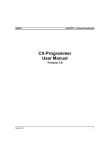
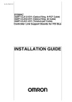
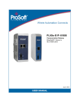
1 to 1 Type
1 to 1 Type Settings
No.
(1)
(2)
(3)
(1)
(2)
(3)
(4)
(4)
(6)
(5)
Slave node
(1) Area and Start Word
1a
1a
1a
1a
1b
1b
1c
1d
1c
2
3
4
(2) Master, Common Send Words
(3) Master, Individual Send Words
(Same as (3).)
1d
(Same as (3).)
(4) Slave, Send Words
Master,
Individual Send
Words
Slave, Send
Words
(5)
Nodes
(6)
Status
3
4
(Same as (4).)
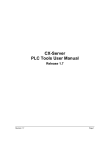
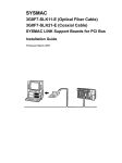
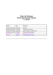
Chain Type
Chain Type Settings
No.
(1)
(2)
(1)
(2)
(3)
Item
Link Area and Start
Word
Master, Common
Send Words
(4)
Each Node,
Receive and Send
Nodes
(5)
Status
(3)
(5)
(4)
(4) Participating nodes
Slave node
Master node
1a
1a
1a
1a
1b
1b
2
3
2
3
4
(2) Master, Common Send Words
(3) Each Node, Received and Sent
Set the send size of the data to send
from the master node to all slave
nodes. The same size of data is sent
to all nodes.
Set the send size for the master node
to sent individually to each slave
node.
Set the send size of the data sent
from each slave node to the master
node.
Set the nodes participating in the data
links.
Set the start word to store data link
status. (If 0 words is set, the default
area will be used.)
2
(Same as (4).)
(1) Area and Start Word
Description of function
Set the area and start data link word.
Features of 1 to 1 Type 1:N Allocation
● Data communications are 1:1 between the master node and slave nodes.
● All slave nodes receive part of the data sent by the master node. In addition,
each slave node receives unique data from the master node (see a to d in
figure).
● The master node receives all data sent by the slaves. The data sizes are
fixed for all nodes.
● Slaves do not send or receive data with other slaves.
● One area is selected from the bit-access areas (e.g., CIO Area) or
word-access areas (e.g., DM Area).
● Data link areas are allocated in ascending order of node addresses.
● Data link participation can be specified for each node.
(5) Participating nodes
Master node
Item
Link Area and
Start Word
Master,
Common Send
Words
2
(Same as (3).)
3
(Same as (3).)
Description of function
Set the area and the start data link
word.
Set the send size of the data to send
from the master node to all slave
nodes. The same size of data is sent
to all nodes.
Set the send size of data for each
node to send to the next node.
Set the nodes participating in the data
links.
Set the start word to store data link
status. (If 0 words is set, the default
area will be used.)
Features of Chain Type 1:N Allocation
● Data communications are 1:1 between the master node and slave nodes.
● All slave nodes receive part of the data sent by the master node (1a in figure).
● The master node receives all data sent by the slaves. The data sizes are fixed
for all nodes.
● Each slave nodes receives data from the previous node and then sends data
to the next node. Data is thus passed in ascending order of the nodes
participating in the data link.
● One area is selected from the bit-access areas (e.g., CIO Area) or
word-access areas (e.g., DM Area).
● Data link areas are allocated in ascending order of node addresses.
● Data link participation can be specified for each node.
4
(Same as (3).)
5. Click the Write Button to transfer the automatic data link setting.
●Adding Nodes while Data Links Are Running
Previous version (version 3.1)
Data link tables could not be
downloaded when data link
were running.
New version (version 3.2)
Nodes can be added while data links are running if both the following Units/Boards and
Repeater Units (CS1W-RPT01) are used.
Applicable models:
Controller Link Units Controller Support Boards
CS1W-CLK21-V1
CS1W-CLK12-V1
CS1W-CLK52-V1
CJ1W-CLK21-V1
3G8F7-CLK21-V1 (-EV1)
3G8F7-CLK12-V1 (-EV1)
3G8F7-CLK52-V1 (-EV1)
Note: Refer to the Controller Link Operation Manual for the procedure to add nodes and
details on changing data link tables while data links are running.
●Up to 62 Nodes for Wired Controller Link Units
Previous version (version 3.1)
Only a maximum of 32 nodes
could be used with Wired
Controller Link Units.
New version (version 3.2)
A maximum of 62 nodes can now be used with Wired Controller Link Units.
Applicable
models:
CS1W-CLK21-V1
CJ1W-CLK21-V1
3G8F7-CLK21-V1 (-EV1)
Note: A CS1W-RPT01 Repeater Unit must be purchased separately to use 62 Controller
Link Units. Refer to the Controller Link Operation Manual for details.
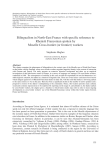
●Displaying Data Link Table Information for Data Link Table Verification
Previous version (version 3.1)
Data link table verification
results were displayed in a
simple list in an Error List
Dialog Box.
New version (version 3.2)
When inconsistencies are detected in data link
verification, the number of inconsistent (failed)
nodes is displayed, and both the data link
settings within the selected PLC and those with
the inconsistencies indicated between pointed
parentheses (< >). (The size of the dialog box
can be changed.) Also, if reading is not possible
for verification, the reasons are displayed.
The results can be pasted as text after clicking a
Copy Button.
●100Base-TX for Ethernet Units
Previous version (version 3.1)
New version (version 3.2)
Only 10Base-T and 10Base-5 were
supported in Unit settings (CPU Bus Unit
setups).
100Base-TX is also supported for Ethernet Unit in the Unit settings (CPU Bus
Unit setups).
Applicable models: CS1W-ETN21, CJ1W-ETN21
●Importing DM/EM Data Files from Previous Support Software
Previous version (version 3.1)
DM/EM data files created with
the SYSMAC Support
Software (SSS) or CV Support
Software (CVSS) could not be
imported from the PLC
Memory Window.
(Importing was possible only
from the File Menu or the File
Conversion Utility.)
New version (version 3.2)
DM/EM data files created with the SYSMAC Support Software (SSS) or CV Support Software
(CVSS) can be imported from the PLC Memory Window.
The following DM/EM data files can be imported.
Support Software
DM/EM data file type (file
name extension)
Memory area
Method used on the SSS/CVSS
SSS
.SP6
.SL4
.DMD
DM
DM
DM
.EDM
EM
.IOM
DM
.IOM
EM
DM data save (All DM)
DM data save (Partial DM save)
DM data save (Bank No.: Base
selected.)
DM data save (Bank No: 0 on
selected.)
File data save (Partial save, Bank
No.: Base selected.)
File data save (Partial save, Bank
No: 0 on selected.)
CVSS
Certain Terms and Conditions of Sale
1. Offer; Acceptance. These terms and conditions (these "Terms") are deemed
part of all catalogs, manuals or other documents, whether electronic or in writing, relating to the sale of goods or services (collectively, the "Goods") by
Omron Electronics LLC and its subsidiary companies ("Seller"). Seller hereby
objects to any terms or conditions proposed in Buyer's purchase order or other
documents which are inconsistent with, or in addition to, these Terms. Please
contact your Omron representative to confirm any additional terms for sales
from your Omron company.
2. Prices. All prices stated are current, subject to change without notice by
Seller. Buyer agrees to pay the price in effect at time of shipment.
3. Discounts. Cash discounts, if any, will apply only on the net amount of
invoices sent to Buyer after deducting transportation charges, taxes and
duties, and will be allowed only if (i) the invoice is paid according to Seller's
payment terms and (ii) Buyer has no past due amounts owing to Seller.
4. Orders. Seller will accept no order less than $200 net billing.
5. Governmental Approvals. Buyer shall be responsible for, and shall bear all
costs involved in, obtaining any government approvals required for the importation or sale of the Goods.
6. Taxes. All taxes, duties and other governmental charges (other than general
real property and income taxes), including any interest or penalties thereon,
imposed directly or indirectly on Seller or required to be collected directly or
indirectly by Seller for the manufacture, production, sale, delivery, importation,
consumption or use of the Goods sold hereunder (including customs duties
and sales, excise, use, turnover and license taxes) shall be charged to and
remitted by Buyer to Seller.
7. Financial. If the financial position of Buyer at any time becomes unsatisfactory
to Seller, Seller reserves the right to stop shipments or require satisfactory
security or payment in advance. If Buyer fails to make payment or otherwise
comply with these Terms or any related agreement, Seller may (without liability
and in addition to other remedies) cancel any unshipped portion of Goods sold
hereunder and stop any Goods in transit until Buyer pays all amounts, including amounts payable hereunder, whether or not then due, which are owing to it
by Buyer. Buyer shall in any event remain liable for all unpaid accounts.
8. Cancellation; Etc. Orders are not subject to rescheduling or cancellation
unless Buyer indemnifies Seller fully against all costs or expenses arising in
connection therewith.
9. Force Majeure. Seller shall not be liable for any delay or failure in delivery
resulting from causes beyond its control, including earthquakes, fires, floods,
strikes or other labor disputes, shortage of labor or materials, accidents to
machinery, acts of sabotage, riots, delay in or lack of transportation or the
requirements of any government authority.
10. Shipping; Delivery. Unless otherwise expressly agreed in writing by Seller:
a. Shipments shall be by a carrier selected by Seller;
b. Such carrier shall act as the agent of Buyer and delivery to such carrier
shall constitute delivery to Buyer;
c. All sales and shipments of Goods shall be FOB shipping point (unless otherwise stated in writing by Seller), at which point title to and all risk of loss of
the Goods shall pass from Seller to Buyer, provided that Seller shall retain a
security interest in the Goods until the full purchase price is paid by Buyer;
d. Delivery and shipping dates are estimates only.
e. Seller will package Goods as it deems proper for protection against normal
handling and extra charges apply to special conditions.
11. Claims. Any claim by Buyer against Seller for shortage or damage to the
Goods occurring before delivery to the carrier must be presented in writing to
Seller within 30 days of receipt of shipment and include the original transportation bill signed by the carrier noting that the carrier received the Goods from
Seller in the condition claimed.
12. Warranties. (a) Exclusive Warranty. Seller's exclusive warranty is that the
Goods will be free from defects in materials and workmanship for a period of
twelve months from the date of sale by Seller (or such other period expressed
in writing by Seller). Seller disclaims all other warranties, express or implied.
(b) Limitations. SELLER MAKES NO WARRANTY OR REPRESENTATION,
EXPRESS OR IMPLIED, ABOUT NON-INFRINGEMENT, MERCHANTABILITY OR FITNESS FOR A PARTICULAR PURPOSE OF THE GOODS.
BUYER ACKNOWLEDGES THAT IT ALONE HAS DETERMINED THAT THE
GOODS WILL SUITABLY MEET THE REQUIREMENTS OF THEIR
INTENDED USE. Seller further disclaims all warranties and responsibility of
any type for claims or expenses based on infringement by the Goods or otherwise of any intellectual property right. (c) Buyer Remedy. Seller's sole obligation hereunder shall be to replace (in the form originally shipped with Buyer
responsible for labor charges for removal or replacement thereof) the noncomplying Good or, at Seller's election, to repay or credit Buyer an amount
equal to the purchase price of the Good; provided that in no event shall Seller
be responsible for warranty, repair, indemnity or any other claims or expenses
regarding the Goods unless Seller's analysis confirms that the Goods were
properly handled, stored, installed and maintained and not subject to contamination, abuse, misuse or inappropriate modification. Return of any goods by
Buyer must be approved in writing by Seller before shipment. Seller shall not
be liable for the suitability or unsuitability or the results from the use of Goods
in combination with any electrical or electronic components, circuits, system
assemblies or any other materials or substances or environments. Any
advice, recommendations or information given orally or in writing, are not to be
construed as an amendment or addition to the above warranty.
13. Damage Limits; Etc. SELLER SHALL NOT BE LIABLE FOR SPECIAL, INDIRECT OR CONSEQUENTIAL DAMAGES, LOSS OF PROFITS OR PRODUCTION OR COMMERCIAL LOSS IN ANY WAY CONNECTED WITH THE
GOODS, WHETHER SUCH CLAIM IS BASED IN CONTRACT, WARRANTY,
NEGLIGENCE OR STRICT LIABILITY. Further, in no event shall liability of
Seller exceed the individual price of the Good on which liability is asserted.
14. Indemnities. Buyer shall indemnify and hold harmless Seller, its affiliates and
its employees from and against all liabilities, losses, claims, costs and
expenses (including attorney's fees and expenses) related to any claim, investigation, litigation or proceeding (whether or not Seller is a party) which arises
or is alleged to arise from Buyer's acts or omissions under these Terms or in
any way with respect to the Goods. Without limiting the foregoing, Buyer (at
its own expense) shall indemnify and hold harmless Seller and defend or settle
any action brought against Seller to the extent that it is based on a claim that
any Good made to Buyer specifications infringed intellectual property rights of
another party.
15. Property; Confidentiality. The intellectual property embodied in the Goods is
the exclusive property of Seller and its affiliates and Buyer shall not attempt to
duplicate it in any way without the written permission of Seller. Notwithstanding any charges to Buyer for engineering or tooling, all engineering and tooling
shall remain the exclusive property of Seller. All information and materials
supplied by Seller to Buyer relating to the Goods are confidential and proprietary, and Buyer shall limit distribution thereof to its trusted employees and
strictly prevent disclosure to any third party.
16. Miscellaneous. (a) Waiver. No failure or delay by Seller in exercising any right
and no course of dealing between Buyer and Seller shall operate as a waiver
of rights by Seller. (b) Assignment. Buyer may not assign its rights hereunder
without Seller's written consent. (c) Amendment. These Terms constitute the
entire agreement between Buyer and Seller relating to the Goods, and no provision may be changed or waived unless in writing signed by the parties.
(d) Severability. If any provision hereof is rendered ineffective or invalid, such
provision shall not invalidate any other provision. (e) Setoff. Buyer shall have
no right to set off any amounts against the amount owing in respect of this
invoice. (f) As used herein, "including" means "including without limitation".
Certain Precautions on Specifications and Use
1. Suitability of Use. Seller shall not be responsible for conformity with any standards, codes or regulations which apply to the combination of the Good in the
Buyer's application or use of the Good. At Buyer's request, Seller will provide
applicable third party certification documents identifying ratings and limitations
of use which apply to the Good. This information by itself is not sufficient for a
complete determination of the suitability of the Good in combination with the
end product, machine, system, or other application or use. The following are
some examples of applications for which particular attention must be given.
This is not intended to be an exhaustive list of all possible uses of this Good,
nor is it intended to imply that the uses listed may be suitable for this Good:
(i) Outdoor use, uses involving potential chemical contamination or electrical
interference, or conditions or uses not described in this document.
(ii) Energy control systems, combustion systems, railroad systems, aviation
systems, medical equipment, amusement machines, vehicles, safety
equipment, and installations subject to separate industry or government
regulations.
(iii) Systems, machines and equipment that could present a risk to life or
property. Please know and observe all prohibitions of use applicable to
this Good.
NEVER USE THE PRODUCT FOR AN APPLICATION INVOLVING SERIOUS
RISK TO LIFE OR PROPERTY WITHOUT ENSURING THAT THE SYSTEM
AS A WHOLE HAS BEEN DESIGNED TO ADDRESS THE RISKS, AND THAT
THE SELLER'S PRODUCT IS PROPERLY RATED AND INSTALLED FOR
THE INTENDED USE WITHIN THE OVERALL EQUIPMENT OR SYSTEM.
2. Programmable Products. Seller shall not be responsible for the user's programming of a programmable Good, or any consequence thereof.
3. Performance Data. Performance data given in this catalog is provided as a
guide for the user in determining suitability and does not constitute a warranty.
It may represent the result of Seller's test conditions, and the user must correlate it to actual application requirements. Actual performance is subject to the
Seller's Warranty and Limitations of Liability.
4. Change in Specifications. Product specifications and accessories may be
changed at any time based on improvements and other reasons. It is our practice to change part numbers when published ratings or features are changed,
or when significant construction changes are made. However, some specifications of the Good may be changed without any notice. When in doubt, special
part numbers may be assigned to fix or establish key specifications for your
application. Please consult with your Seller's representative at any time to confirm actual specifications of purchased Good.
5. Errors and Omissions. The information in this catalog has been carefully
checked and is believed to be accurate; however, no responsibility is assumed
for clerical, typographical or proofreading errors, or omissions.
OMRON
PART1: CX-Programmer
TABLE OF CONTENTS
Precautions......................................................................................................... iv
CHAPTER 1 Technical Specifications............................................................. 1
CX-Programmer Software .....................................................................................................................................1
About this Manual .................................................................................................................................................1
CX-Programmer Features ......................................................................................................................................1
System Requirements ............................................................................................................................................3
Installation ...........................................................................................................................................................3
Help and How to Access it ....................................................................................................................................4
Technical Support ..................................................................................................................................................6
CHAPTER 2 Quick Start Guide ...................................................................... 9
Starting CX-Programmer .......................................................................................................................................9
Licensing ...........................................................................................................................................................9
Introducing CX-Programmer Projects .................................................................................................................10
The CX-Programmer Environment......................................................................................................................10
Using CX-Programmer ........................................................................................................................................16
Summary .........................................................................................................................................................24
CHAPTER 3 Project Reference ..................................................................... 25
Project Workspace ...............................................................................................................................................25
Program Sections .................................................................................................................................................25
Cross-Reference Report.......................................................................................................................................28
Address Reference Tool.......................................................................................................................................28
Output Window ...................................................................................................................................................29
Watch Window ....................................................................................................................................................30
Options and Preferences ......................................................................................................................................31
Finding and Replacing .........................................................................................................................................37
Properties .........................................................................................................................................................41
Using Microsoft Windows Features in CX-Programmer.....................................................................................43
CHAPTER 4 Reference ................................................................................... 51
PLCs and Projects................................................................................................................................................51
Symbols
.........................................................................................................................................................52
Program Editing...................................................................................................................................................60
Memory View......................................................................................................................................................67
Mnemonic Program Editing.................................................................................................................................68
Working On-line ..................................................................................................................................................68
Flash ROM Backup .............................................................................................................................................77
Data Trace/Time Chart Monitoring .....................................................................................................................79
CX-Net Network Configuration Tool..................................................................................................................79
IO Table
.........................................................................................................................................................79
CHAPTER 5 Advanced Topics....................................................................... 81
Writing More Maintainable Programs .................................................................................................................81
Copying Information between Projects................................................................................................................81
Using CX-Programmer with Other Applications.................................................................................................82
Converting Programs between PLC Types ..........................................................................................................84
Applying a Password to the PLC Programs.........................................................................................................85
APPENDIX A Toolbars and Keyboard Shortcuts ....................................... 87
Standard Toolbar .................................................................................................................................................87
Diagram Toolbar..................................................................................................................................................88
Insert Toolbar.......................................................................................................................................................88
Symbol Table Toolbar .........................................................................................................................................88
PLC Toolbar ........................................................................................................................................................89
Program Toolbar..................................................................................................................................................89
Views Toolbar .....................................................................................................................................................90
CX-Programmer_Page (xvii)
OMRON
PART1: CX-Programmer
Keyboard Shortcuts ......................................................................................... 91
Default CX-Programmer Keyboard mapping ......................................................................................................91
Default SYSMAC Support Soft Keyboard mapping ...........................................................................................93
GLOSSARY OF TERMS................................................................................ 95
CX-Programmer_Page (xviii)
PART 1: CX-Programmer
CHAPTER 1 – Technical Specification
OMRON
CHAPTER 1
Technical Specifications
This chapter describes the CX-Programmer software in general terms and provides details of the operating
environment and minimum configuration necessary for the satisfactory operation of CX-Programmer.
CX-Programmer Software
CX-Programmer is a PLC programming tool for the creation, testing and maintenance of programs associated
with Omron CS/CJ-series PLCs, CV-series PLCs and C-series PLCs. It provides facilities for the support of
PLC device and address information and for communications with OMRON PLCs and their supported network
types.
CX-Programmer operates on IBM compatible personal computers with Pentium or better central processors,
including Pentium II. It runs in a Microsoft Windows environment (Microsoft Windows 95, 98, Millennium,
2000 or XP and NT4.0 with Service Pack 5 or later).
About this Manual
This User Manual acts as a reference for CX-Programmer by describing its various concepts and abilities, and
by leading the user through the basics of CX-Programmer programming. It also provides a detailed reference
for all of the CX-Programmer functions.
Separate OMRON manuals describe the PLC programming structure and instruction set in detail. A separate
OMRON manual describes the common features to PLC programming used by software other than CXProgrammer.
CX-Programmer comes with a context sensitive on-line help system which is designed to
complement this manual and to provide a quick reference at any point while using CXProgrammer when the manual is not to hand. This general help system uses a fast ‘hypertext
system’ which allows progressively more information about any topic to be obtained by
selecting keywords within the descriptive text.
Throughout this manual it is assumed that the reader has a working knowledge of Microsoft Windows, and
knows how to:
♦
Use the keyboard and mouse.
♦
Select options from Microsoft Windows menus.
♦
Operate dialogue boxes.
♦
Locate, open and save data files.
♦
Edit, cut and paste text.
♦ Use the Microsoft Windows desktop environment.
If Microsoft Windows has not been used before, it is recommended that the reader spends some time working
with it using the Microsoft documentation before using CX-Programmer.
This manual also assumes that a working knowledge of OMRON PLC devices has been obtained.
CX-Programmer Features
CX-Programmer is a support tool for the programming of OMRON PLCs and for maintenance of their device
settings. It supersedes the OMRON applications SYSWIN and SYSMAC-CPT.
The following list describes important features that were present in CX-Programmer 2.1.
♦
Support for new PLCs – Full support has been added for the, CS1G-H, CS1H-H and CJ1G, CJ1G-H, CJ1HH series PLCs and the D/S Gateway PLC (CPM2*-S*).
♦
Flash ROM backup – Flash ROM backup is supported for the PLCs incorporating this feature.
♦
Find and Replace – Enhanced and extended Find and Replace functionality. The GUI has been enhanced to
include the scope of the search i.e. whether the Section, Global symbol and/or the Local symbol will be
affected by the search.
CX-Programmer _Page 1
PART 1: CX-Programmer
CHAPTER 1 – Technical Specification
OMRON
♦
Upload/Download – The Upload/Download functionality has been updated to include the CV/CVM1,
CS1/CJ1, CJ1H/H-H and CS1G/H-H PLCs to avoid searching section markers on the initial dialog Upload.
♦
The range of the Send/Rec. instruction has been extended to include the PLCs CS1/CJ1, CS1G/H-H and
CJ1G/H-H
♦
Operation – The levels of operation have been extended to include Junior, Demo and Trial versions of the
product.
♦
Symbol Sorting – The symbol sort for number data types has been enhanced and is now sorted separately
from other data types in the symbol table view.
♦
Direct import file range extended to include CPT, SP1 and COD files.
Version 3.0 of CX-Programmer offers the following enhancements.
♦
Support for new PLCs – Full support has been added for the, CJ1M, and CS1D series PLCs.
♦
Changed the sizes and positions of dialogs for editing Contact/Coil/Instruction, Find and Replace, and
Commented Rung.
♦
Auto Online, Work Online Simulator - Enhanced the online functionality making it easier to connect to
PLCs and debug programs.
♦
Combine and Split rungs - The combine and split functions have been added making it easy to add and
divide rungs.
♦
Watch Window - The watch window has been enhanced to enable addresses to be entered directly on the
watch sheet.
♦
Key Mapping - The data of Keyboard Mapping can be saved to a file (*.mac) and loaded into a CXProgrammer.
♦
Section/Rung Manager - A function to edit a structure of Program is supported. Sections, Rungs and
comments can be edited on this dialog.
♦
I/O Comment view - A View to edit comments of addresses is now supported.
CX-Programmer supports the following PLCs.
Series
Model
CPU Types
CJ-Series
CJ1G
CJ-Series
CJ1G-H
CPU 42, CPU 43, CPU 44, CPU 45
CJ-Series
CJ1H-H
CPU 65, CPU 66
CPU 44, CPU 45
CJ-Series
CJ1M
CPU 12, CPU 13, CPU 22, CPU 23
CS-Series
CS1G
CS1G-H
CPU 42, CPU 43, CPU 44, CPU 45
CS-Series
CS1H
CS1H-H
CPU 63, CPU 64, CPU 65, CPU 66, CPU 67
CV-Series
CV1000
CPU 01
CV-Series
CV2000
CPU 01
CV- Series
CV500
CPU 01
CV- Series
CVM1
CPU 01, CPU 11
CV- Series
CVM1-V2
C- Series
C1000H
CPU 01
C- Series
C2000H
CPU 01
C- Series
C200H
CPU 01, CPU 02, CPU 03, CPU 11, CPU 21,
CPU 22, CPU 23, CPU 31
CPU 01, CPU 11, CPU 21
C- Series
C200HE
CPU 11, CPU 32, CPU 42
C- Series
C200HE-Z
CPU 11, CPU 32, CPU 42
C- Series
C200HG
CPU 33, CPU 43, CPU 53, CPU 63
C- Series
C200HG-Z
CPU 33, CPU 43, CPU 53, CPU 63
C- Series
C200HS
CX-Programmer _Page 2
CPU 01, CPU 03, CPU 21, CPU 23, CPU 31,
CPU 33
PART 1: CX-Programmer
CHAPTER 1 – Technical Specification
OMRON
Series
Model
C- Series
C200HX
CPU Types
C- Series
C200HX-Z
CPU 34, CPU 44, CPU 54, CPU 64, CPU 65,
CPU 85
C- Series
CPM1
(CPM1A)
CPU 10, CPU 20, CPU 30, CPU 40
C-Series
CPM2*
CPM2*-S*
–
C- Series
CQM1
C- Series
CQM1H
IDSC
–
CPU 34, CPU 44, CPU 54, CPU 64
CPU 11, CPU 21, CPU 41, CPU 42, CPU 43,
CPU 44, CPU 45
CPU 11, CPU 21, CPU 51, CPU 61
–
SRM1
SRM1
C01, C02
SRM1
SRM1-V2
C01, C02
Note:
The CVM1-V1 PLC for types CPU01 and CPU11 cannot be specifically selected. Use the
non V2 types.
Refer to the CX-Server PLC Tools User Manual for information regarding available communication types.
System Requirements
CX-Programmer operates IBM PC-AT compatible or NEC PC-98 compatible computers with Pentium II class
or better. central processor. It runs in a Microsoft Windows environment (Microsoft Windows 95, 98,
Millennium, 2000 or XP and NT4.0 with Service Pack 5 or later).
Note:
CX-Programmer is not guaranteed to be compatible with computers running Windows
emulation (for example, Apple Macintosh).
The following configurations are the minimum system requirements for running CX-Programmer in Microsoft
Windows 95, 98, Millennium, 2000 or XP and NT4.0 with Service Pack 5 or later).
Minimum System Requirements
Minimum Specification
Recommended Minimum Specification
Operating
System
CPU
Type
Memory
(RAM)
HDD
Space
Display
CPU
Type
Memory
(RAM)
HDD
Space
Display
Windows 95
Pentium
Class
32Mb
100Mb
800x600
Pentium
Class II
64Mb
150Mb
1024x768
Windows 98
Windows NT
(with SP 5)
SVGA
133MHz
Windows
2000
Pentium
Class
Windows ME
150MHz
Windows XP
Home
Pentium
Class II
Windows XP
Professional
300MHz
SVGA
200MHz
64Mb
100Mb
800x600
SVGA
Pentium
Class
64Mb
150Mb
1024x768
SVGA
200MHz
128Mb
100Mb
800x600
SVGA
Pentium
Class II
256Mb
150Mb
1024x768
SVGA
600MHz
Use of a mouse is highly recommended, although all operations can be performed using the keyboard. Refer to
Appendix C for a list of keyboard shortcut commands.
The amount of RAM and hard disk space used depends upon the size of the PLC programs written –
approximately 1K per step.
Installation
This chapter describes the procedures involved in the installation of CX-Programmer on a standard workstation
running Microsoft Windows 95, 98, Millennium, 2000 or XP and NT4.0 with Service Pack 5 or later.
CX-Programmer _Page 3
PART 1: CX-Programmer
CHAPTER 1 – Technical Specification
OMRON
The software is supplied on CD-ROM and is installed easily from within Microsoft Windows. The installation
can be terminated at any point during the installation process.
During the installation process, the Software Licence Agreement will be displayed. This informs you of
Omron’s terms and conditions concerning the software licensing of CX-Programmer. These must be read and
agreed with before continuing.
1, 2, 3…
1.
Insert the CD in the appropriate CD-ROM drive. If autorun is set, you will automatically
be taken to the Install screen. If not, select Start then the Run option from the Start
pushbutton on the Microsoft Windows taskbar.
2.
Click the Browse pushbutton to select the setup file from the CD-ROM drive.
3.
Click the OK pushbutton to initiate the installation. Follow the on-screen instructions.
Entering a Licence Number
During the installation, a licence number must be entered. The licence number is supplied with the purchase of
CX-Programmer. There are eight different licence number types representing eight different modes of
installation. Upgrade licence numbers are available on request.
The eight installation modes are:
Full (1 User)
Installation providing full functionality support for all PLCs.
The licence is restricted to a single user installation.
Full (3 User)
Installation providing full functionality support for all PLCs.
The licence is restricted to a three user installation.
Full (10 User)
Installation providing full functionality support for all PLCs.
The licence is restricted to a ten user installation.
Multiple User
Installation providing full functionality support for all PLCs.
The licence is restricted to a multiple user installation.
Junior
Installation providing full functionality support for the junior range PLCs only
CPM1 (CPM1A), CPM2*, SRM1, SRM1-V2.
The licence is restricted to a single user installation.
Multiple User
(Junior)
Installation providing full functionality support for the junior range PLCs only
CPM1 (CPM1A), CPM2*, SRM1, SRM1-V2.
The licence is restricted to a multiple user installation.
Trial
Installation providing full functionality support for all PLCs. Its use is limited to 30 days
from time of installation.
The licence is restricted to a single user installation.
Demonstration
Installation providing limited functionality support for all PLCs. Full system operation is
provided but projects can not be saved or printed.
If no licence number is entered then CX-Programmer is automatically installed in demonstration mode.
If CX-Server was included in the installation then on completion of the CX-Programmer installation a number
of dialogs will prompt for information concerning the installation of CX-Server and its components.
Help and How to Access it
CX-Programmer comes with a detailed context-sensitive help system. At any time while using the software, it
is possible to get help on the particular point that is currently being worked on, or on general aspects of CXProgrammer. This system is intended to complement the manual, by providing an on-line reference to specific
functions of the software. The manual is designed to provide tutorial information and discuss the various
facilities offered by CX-Programmer.
♦
Help topics (available from the Help menu);
♦
Instruction Reference (available from the Help menu and from the instruction entry dialogue);
♦
Context sensitive help;
♦
About (available from the Help menu);
♦
Status Bar.
CX-Programmer _Page 4
PART 1: CX-Programmer
CHAPTER 1 – Technical Specification
OMRON
Help Topics
Select the Help Topics option on the Help menu. The Help system provides a standard look-up dialogue under
the Contents tab showing the contents of the CX-Programmer Help file. Double-click on an item to read the
associated information.
Index
Use the following procedure to retrieve on-line help from the Index tab of the Help Topics dialogue.
1, 2, 3…
1.
Select the Help Topics option from the Help menu.
2.
Select the Index tab.
3.
Enter a text query into the first step field. The second step field is refreshed according to
the query entered in the first step field.
4.
Select an entry in the second step field and select the Display pushbutton, or double-click
on the index entry.
5.
If an entry is linked to two or more topics, the names of the topics are displayed in the
Topics Found dialogue. Select a topic and choose the Display pushbutton or double-click
on the topic.
Find
Use the following procedure to retrieve on-line help from the Find tab of the Help Topics dialogue.
1, 2, 3…
1.
Select the Help Topics option from the Help menu.
2.
Select the Find tab.
3.
Enter a text query into the first step field. The second step field is refreshed according to
the query entered in the first step field. Previous text queries can be retrieved by selecting
from the drop-down list in the first step field.
4.
Select a word that matches the query – some words may be automatically selected. More
than one word can be selected by pressing Shift and selecting another word to extend the
selection or by pressing Ctrl and selecting another word to add to the selection. The third
step field is refreshed according to the word or words selected. The number of topics
found is shown at the bottom of the dialogue.
5.
Select a topic from the third step field and select the Display pushbutton, or double-click
on the topic from the third step field. Select the Clear pushbutton to restart the Find
operation.
The Find operation can be enhanced by the use of the Options pushbutton and Rebuild push-button. Refer to
Microsoft Windows documentation for further information.
Instruction Reference
CX-Programmer supports additional help for CS/CJ-series PLCs, CV-series PLCs and C-series PLCs. All valid
instructions relating to PLC programming can be retrieved by selecting Instruction Reference from the Help
menu, followed by either CS/CJ-Series, CV-Series or C-Series. Individual help topics are displayed.
Keyboard Mapping Reference
CX-Programmer supports a function to customise the keyboard mapping, and provides default keyboard
mapping files for CX-Programmer, SYSWIN and SYSMAC Support Software. A list of each keyboard
mapping file is displayed.
Note:
Guidance can be displayed for CX-Programmer functions for SYSMAC Support Software
operations and SYSWIN operations by selecting Function Key Guidance from the View
menu. The CX-Programmer shortcut key allocations for all keys can be displayed by selecting
Information Window from the View menu.
Context Sensitive Help
CX-Programmer supports the use of context sensitive help. The relevant on-line help topic is provided
automatically by selecting the current area of the display responsible for carrying out those actions. Select the
F1 function key to retrieve context sensitive help. Some dialogs include a Help pushbutton when F1 cannot be
accessed.
CX-Programmer _Page 5
PART 1: CX-Programmer
CHAPTER 1 – Technical Specification
OMRON
It is also possible to retrieve context sensitive help by selecting the Help button from the
toolbar and selecting an area of the display to retrieve help.
About CX-Programmer
CX-Programmer includes an About button accessible from the toolbar. The About CXProgrammer dialogue supplies technical reference information about the application such as
version and copyright information. It also contains essential version number information that
is required for obtaining technical support.
Status Bar
The status bar is displayed at the bottom of many of the CX-Programmer display and tool windows. It provides
several helpful pieces of information while programming:
♦
Instant Help. A brief message appears in the status bar as menu commands and buttons are selected.
♦
On-line Status. This shows the on-line or off-line status of the PLC. If connection to a PLC is lost, the
status bar will indicate this by flashing.
♦
Network and Node number. This shows the network number and the node number of the current PLC,
which the cursor is pointing at. When connected to a simulator, Simulator will be displayed instead.
♦
PLC Operating Mode. When connected to a PLC, this shows the current PLC mode. Connection errors are
also displayed here.
♦
Connected PLC and CPU Type.
referenced in the status bar.
♦
PLC Cycle Time. This shows the current cycle time of the PLC when connected.
♦
Cursor Position. This shows the position of the cursor within the program.
♦
On-line Edit Buffer Size. This shows the size remaining in the on-line edit buffer when connected to a PLC
and editing on-line.
The currently connected PLC and associated CPU can always be
♦ PLC memory backup. This shows the status of the PLC memory backup.
The CX-Programmer status bar can be enabled and disabled by selecting the Status Bar option from the View
menu.
Technical Support
If the installation instructions for this application have been followed (refer to Chapter 1 - Installation), no
difficulties should be encountered. However, if there is a problem, contact Customer Services.
If a problem occurs, check that it does not relate to a fault outside CX-Programmer, for instance, with CXServer components. Check the following:
♦
The computer is working correctly.
♦
The PLC is working correctly.
♦
The communications system is set up correctly.
♦ The errors are cleared in the PLC.
When Customer Services need to be contacted, keep the following details to hand. A clear and concise
description of the problem is required, together with the exact text of any error messages.
Note:
CX-Programmer _Page 6
Use the About dialogue to obtain the version number of the application (the four-fielded
version listed against the ‘CX-P.exe’ entry in the bottom list).
PART 1: CX-Programmer
CHAPTER 1 – Technical Specification
OMRON
Customer Services Request Form
Version number of CXProgrammer:
Serial number of the software:
Operating
number:
system
and
version
Language of operating system:
PLC type, model and CPU details:
Type of communications in use:
Serial
SYSMAC LINK
SYSMAC NET
Controller Link
Ethernet
Toolbus
Nature of the problem:
Steps taken to reproduce problem:
Other comments:
Refer to the CX-Server PLC Tools User Manual for support details regarding CX-Server components.
CX-Programmer _Page 7
PART 1: CX-Programmer
CHAPTER 2 – Quick Start Guide
OMRON
CHAPTER 2
Quick Start Guide
This chapter describes the basic features of CX-Programmer together with a simple tutorial for familiarisation
purposes; detail is to be found in Chapter 3 - Project Reference and Chapter 4 - Reference.
As this chapter proceeds, important concepts about CX-Programmer are introduced by this
symbol.
Starting CX-Programmer
CX-Programmer is activated from the Start button in the Microsoft Windows taskbar. Once
activated, CX-Programmer is displayed.
CX-Programmer provides the facility to create a project file in which as many PLCs as required can be included.
For each PLC, ladder program(s), addressing and network details, pre-set PLC memory, IO table, expansion
instructions (if applicable) and programming symbols can be defined.
Licensing
CX-Programmer uses a licence number system in order to activate the programme in one of four modes of
operation. The licence number for the mode of operation purchased is shown on the CD case.
Junior Mode
To use CX-Programmer in Junior mode, a licence number is required. Using this mode provides full
functionality but restricts programming to the CPM1(CPM1A), CPM2*, SRM1 and SRM1-V2 PLCs only.
Trial Mode
A licence number is required to run CX-Programmer in Trial mode. Full functionality is provided is this mode
but operation is restricted to 30 days from the time installation.
Demo Mode
A licence number is not required to run CX-Programmer in Demo mode. Full system operation is provided but
projects can not be saved or printed.
CX-Programmer _Page 9
PART 1: CX-Programmer
CHAPTER 2 – Quick Start Guide
OMRON
Full Version
To access the Full Version of CX-Programmer, the appropriate licence number must be entered.
The licence number may be input at the time of installation or later. To enter an upgrade licence number or reenter the existing number after installation, follow these steps:
1, 2, 3…
1.
Start CX-Programmer, as described above.
2.
Click the help button in the toolbar or from the Help menu select the About CXProgrammer option.
3.
In the ‘About CX-Programmer’ dialog click the Licence button.
4.
A dialogue is displayed that allows a new licence number to be entered. Read the warning
message, enter the appropriate licence number and click OK.
5.
When a correct licence number is entered, CX-Programmer must be restarted to gain full
functionality.
Introducing CX-Programmer Projects
The information within a CX-Programmer project consists of ladder program(s), operands,
required PLC memory contents, IO tables, expansion instructions (if applicable) and symbols.
Each CX-Programmer project file is separate and is a single document.
CX-Programmer can only open a single project at a time. However, it is possible to deal with
many project files by using CX-Programmer at once.
A CX- Programmer project has a .CXP or .CXT file extension. (Normally the .CXP file is
used, and is a compressed version of the .CXT file).
Once the project itself is created the desired PLC and symbol information can be defined. For a full discussion
of PLCs, refer to the CX-Server - PLC Tools User Manual.
The CX-Programmer Environment
This chapter describes how to manipulate the different views of the main window. Use this
chapter to develop an understanding with the layout of CX-Programmer and to customise it
according to specific requirements.
CX-Programmer _Page 10
PART 1: CX-Programmer
CHAPTER 2 – Quick Start Guide
OMRON
The views available are controlled via the options supplied by the View menu.
The project workspace. Select the Toggle Project Workspace button from the toolbar to
activate this view. Deselect the Toggle Project Workspace button from the toolbar to
deactivate this view.
The Output window. Select the Toggle Output Window button from the toolbar to activate
this view. Deselect the Toggle Output Window button from the toolbar to deactivate this
view.
The Watch window. Select the Toggle Watch Window button from the toolbar to activate this
view. Deselect the Toggle Watch Window button from the toolbar to deactivate this view.
The Cross Reference Report. Select the Cross Reference Report button from the toolbar to
activate this view.
The local symbol table. Select the View Local Symbols button from the toolbar to activate
this view.
The Diagram Workspace. Select the View Diagram button from the toolbar to activate this
view.
The Mnemonics view. Select the View Mnemonics button from the toolbar to activate this
view.
The Address Reference tool. Select the Show Address Reference Tool button from the
toolbar to activate this view.
The I/O Comment view. Select the I/O Comment view button from the toolbar to activate this
view.
The Properties dialogue. Select the Show Properties button from the toolbar to activate this
view.
The Monitor in HEX. Select the Monitor in HEX button from the toolbar to activate this
function.
All windows in the CX-Programmer main window can be minimised, maximised or closed.
Refer to standard Microsoft Windows documentation for further information.
Each window has an associated context menu obtained by clicking the right-mouse button. These options show
the functions relevant to the point where the right-mouse button was pressed.
The status bar displays instant help, Network and Node numbers of current PLC, PLC on-line status, PLC mode,
connected PLC and PLC type, PLC cycle time, on-line edit buffer size and current cursor position depending on
which view is displayed.
To exit CX-Programmer, select Exit from the File menu.
Refer to Chapter 3 - Project Reference for further information.
Project Workspace
The project workspace displays the project as a hierarchical tree structure showing related
PLC and program details. Select the Toggle Project Workspace button from the toolbar to
activate this view. Deselect the Toggle Project Workspace button from the toolbar to
deactivate this view.
CX-Programmer _Page 11
PART 1: CX-Programmer
CHAPTER 2 – Quick Start Guide
OMRON
A description of each object in the hierarchy and their associated context menus is provided as follows:
PLC. Refer to the CX-Server PLC Tools User Manual for details.
Global Symbol Table. Refer to Chapter –2 Introducing Symbols and the Symbol Table for
details.
IO Table. Refer to the CX-Server PLC Tools User Manual for details.
PLC Settings. Refer to the CX-Server PLC Tools User Manual for details.
Memory Card. Refer to the CX-Server PLC Tools User Manual for details. The Memory
Card object can only be selected when the PLC is on-line.
Error Log. Refer to the CX-Server PLC Tools User Manual for details. The Error Log object
can only be selected when the PLC is on-line.
PLC Memory. Refer to the CX-Server PLC Tools User Manual for details.
Program. Refer to Chapter –2 Using CX-Programme for details.
Local Symbol Table. Refer to Chapter –2 Introducing Symbols and the Symbol Table for
details.
Sections. Refer to Chapter – 2 Program Sections.
Collapse/Expand. The hierarchy can be collapsed or expanded to show either a partial view or
full view of the project workspace tree.
Diagram Workspace
The Diagram Workspace can display a Ladder program, the symbol table of that program, the Mnemonics view
and the I/O Comment view. The details displayed depend upon the selection made in the project workspace.
When a new project is created or a new PLC added to a project, an empty Ladder program is automatically
displayed on the right-hand side to the project workspace. The symbol table, the Mnemonics view and the I/O
Comment view must be explicitly selected to be displayed. All views can be opened at the same time and can
be selected via options associated with the Window menu.
The Ladder program graphically represents the PLC power flow from left to right and the program sequence
from top to bottom.
PLC program instructions can be entered as a graphical representation in Ladder form. Programs can be created,
edited and monitored in this view.
Follow the examples provided to develop an understanding of the Diagram Workspace.
Select the View Diagram button from the toolbar. The Ladder program window is displayed
in the Diagram Workspace.
CX-Programmer _Page 12
PART 1: CX-Programmer
CHAPTER 2 – Quick Start Guide
OMRON
The following items are standard features of the Ladder program area:
♦
Cursor. A rectangular block showing the current position within the rung. The location of the cursor is
displayed in the status bar.
♦
Rung. A logical unit of a ladder program. A rung can encompass one or more rows and columns. All
rungs are numbered.
♦
Bus-bars. The left bus-bar provides a graphical representation of the power supply bus-bar. The right busbar contains the output region: to align objects to the right bus-bar. The right bus-bar is selectable for
display. If shown, the ladder rungs are justified so that the outputs of the rungs are organised along it.
♦
Grid Dots. Dots that display at the connection points of each cell. To display the grid, select the Grid
button from the toolbar.
♦
Rung Margin Area. The area to the left of the Left bus-bar. The rung number and step number for each
rung are shown here (rung number on the left).
♦
Automatic Error Detection. A bar is displayed to the left of the currently selected rung area. As elements
and instructions are added to the rung, the additions are automatically checked to see if they are valid. The
colour of the bar indicates the validity of the program: red highlights an error, whilst green indicates a
correct entry. In addition, elements of the text on the ladder are drawn in this error colour if a problem
exists.
The colour and display preferences of the above features can be amended by selecting Options from the Tools
menu.
More than one element in a rung can be selected by pressing the mouse button down on an element and, keeping
the left-mouse button depressed, dragging a highlight over other elements in the rung. Selected elements can
then be moved as a block.
Mnemonics View
The Mnemonics view is a formatted editor for programming in mnemonic instructions. This view is made up of
a table of six columns containing the rung number, step number, instruction, operands, value and comment.
Mnemonic instructions are a ‘low-level’ view of a PLC program, whilst ladder is higher. Since the ladder
program is just a higher level representation of the mnemonic instructions, it is possible to type in mnemonics
and see the ladder program update.
Select the View Mnemonics button from the toolbar. The Mnemonics view is displayed in the
Diagram Workspace.
CX-Programmer _Page 13
PART 1: CX-Programmer
CHAPTER 2 – Quick Start Guide
1, 2, 3…
OMRON
1.
To program in mnemonics, open the mnemonic view and place the cursor on the desired
instruction.
2.
Press ENTER – this will enter the editing mode.
3.
Edit or type the new instruction lines. A mnemonic instruction consists of an instruction
name followed by a set of operands separated by spaces (e.g. ‘MOV #1 A2’).
4.
Either press ENTER to move to the next line, or press ‘down’ or ‘up’ on the keyboard to
move to another line – the updated line is still kept.
The newly entered information is separated out over the columns in the table.
5.
When finished with editing, press ‘Esc’ to come out of editing mode.
Whilst entering a program in the mnemonics view, the ladder view shows the instructions in the new rung as
statement list. Once enough instructions have been entered to enable its drawing in ladder format it is redrawn.
Instructions can be transferred to and from the Mnemonics view using the standard Microsoft Windows Cut or
Copy and paste functions. For example, it is possible to paste a large amount of program from a text editor.
Refer to Chapter 3 - Project Reference for further information.
Introducing Symbols and the Symbol Table
PLC addresses, which are used as operands in a PLC program, can be assigned a symbolic name and/or a
comment for the purpose of reference during programming. An address with a name or comment is known as a
Symbol.
A symbol table is an editable list of symbol definitions – the names, addresses and comments. This list also
provides information on the following:
♦
Rack location. If the address is contained within the PLC IO table, this shows the address’ rack location.
♦
Usage. If the address is contained within the PLC IO table, this shows the physical hardware type (i.e.
‘Input’ or ‘Output’) which is mapped to the address. If no hardware is mapped, ‘Work’ is shown, meaning
that the symbol is for general use.
It is possible to indicate the physical format of the data that is stored at an address. This additional data typing
facility enables CX-Programmer to check whether the address is used consistently within programs. In the
symbol tables, an icon is shown next to a symbol that indicates its data type. The Data Type set is as follows:
Data Type
Data Type Description
BOOL
Address of a binary bit - a logical Boolean on or off state. This type is
typically used for contacts or coils.
CHANNEL
This is a special data type, for backward compatibility. It is an address (nonbit) to data of any type (unsigned or signed, one or more words), so can be
used in place of any of the above data-types except NUMBER and BOOL.
The data type is weak, and so checking is limited (e.g. CX-Programmer
cannot check if the address is being used for BCD or binary values).
DINT
Address of a signed, double binary word.
INT
Address of a signed, single binary word.
LINT
Address of a signed, quad binary word.
NUMBER
A literal numeric value - not an address. The value can be signed, or floating
point. NUMBERs are used for any literal value or for timer/counter identifiers
(for TIM/CNT, only unsigned integer values are allowed).
Floating point values are only suitable within IEEE REAL type operands.
CX-Programmer _Page 14
Icon
PART 1: CX-Programmer
CHAPTER 2 – Quick Start Guide
OMRON
Note: When used as BCD number operands, the value is treated as if it
were entered in decimal with a ‘#’ on the front. E.g. using a NUMBER ‘1234’
is equivalent to typing ‘#1234’ as the operand, so that the decimal
interpretation is made of the value.
The value of a NUMBER data type is assumed to be decimal, unless it is
prefixed with '#' for a hexadecimal value.
Note: NUMBERs entered in hexadecimal are converted to decimal for BCD
operands (e.g. a NUMBER defined as ‘#10’ will appear as ‘#16’ for a BCD
operand).
REAL
Address of a double word floating point value (IEEE format - use the UDINT
type for the BCD, FDIV format).
LREAL
Address of a long word floating point value (IEEE format - use the ULINT
type for the BCD format).
UDINT
Address of an unsigned, double binary word.
UDINT_BCD
Address of an unsigned, double BCD word.
UINT
Address of an unsigned, single binary word.
UINT_BCD
Address of an unsigned, single BCD word
ULINT
Address of an unsigned, quad binary word.
ULINT_BCD
Address of an unsigned, quad BCD word.
Each program within a PLC has a ‘local’ symbol table that consists of symbols that are for use specifically in
that program. Each PLC within a project has a ‘global’ symbol table that consists of symbols that can be used in
any of its programs. When a PLC is added to a project, its global symbol table is filled with a pre-set list of
symbols, dependant upon PLC type.
Each symbol name must be unique within its table. However, it is possible to use the same name in a local and
a global table – in this case, the local symbol takes precedence over the global symbol of the same name.
The symbol table allows these names to be entered and edited directly. Each symbol name
must be unique. Use the following procedure to activate the symbol tables.
1, 2, 3…
1.
Double-click on the symbol table object beneath the PLC in the project workspace. The
global (i.e. PLC’s) symbol table is displayed containing global symbols.
CX-Programmer _Page 15
PART 1: CX-Programmer
CHAPTER 2 – Quick Start Guide
OMRON
Double-click on the symbol table object beneath a program in the project. The program’s
local symbol table is displayed.
Using CX-Programmer
This chapter contains an example tutorial and also describes basic procedures which should be
considered before performing any programming task on the computer and preparing ladder
programs with CX-Programmer, and how to use the various tools to improve productivity.
CX-Programmer offers many methods of working with its tools: in general, instructions are
given for using the toolbar icon in the first instance.
The following tutorial has been based on a CS1H PLC. The choice of PLC made here affects a number of other
parameters that may need to be set up. For example, the CV-series requires setting up the IO table, and using
the Settings object in the Project hierarchy to establish specific PLC characteristics.
When planning a PLC programming project, various items need to be considered and set up within CXProgrammer before beginning to lay down program instructions. For example, it is important for CXProgrammer to know the model and configuration of the PLC to be programmed, so that it can establish the
correct program checking and communications for that PLC. Programming should be targeted at the PLC that is
to be used. It is possible to change the PLC type at any time - the program(s) are then converted. However,
since the conversion may not be perfect, it is best to set the correct PLC type at the beginning.
Before programming, it is recommended that a checklist of the important program aspects be
constructed, including its structure and PLC parameters. To start a new project in CXProgrammer, follow these steps in addition to the basic procedure outlined in your PLC
programming manual:
CX-Programmer _Page 16
PART 1: CX-Programmer
CHAPTER 2 – Quick Start Guide
OMRON
Step
Include
Determine PLC essential parameters
PLC series, PLC type, CPU (where applicable),
communications interface, choice of editor and project type.
Determine allocation of PLC memory
Where applicable. For example, C-series PLCs require
working out the balance required between program memory
and expansion data memory.
Determine PLC setup parameters
PLC configuration data.
Create appropriate IO Table
List all related IO devices and addresses. Some C-series
PLCs do not support this function.
Decide how to input and edit the program
CX-Programmer offers two languages: ladder and mnemonic.
A mixture may be used.
Starting a New Project
Once the project requirements have been worked out on paper, the first step is to create a project and define the
device entries for that project. A project can have multiple PLCs. CS/CJ-series PLCs are multi-tasking and can
therefore have more than one program associated with them in the project; CV-series PLCs and C-series PLCs
can only have one program associated with the device.
Use the following procedure to create a new project.
1, 2, 3…
1.
Select the New button from the toolbar.
2.
Define the device entries for the project. Refer to the CX-Server PLC Tools User Manual
for further information. For this tutorial, set the PLC type as CS1H with CPU type
CPU67.
3.
Save the project. Select the Save Project button from the toolbar. The Save CXProgrammer File dialogue is displayed.
4.
Type a valid file name in the File Name field. Select the Save pushbutton to save the new
project. Select the Cancel pushbutton to abort the operation.
When a new PLC is added to a project, the following empty tables are created:
♦
♦
♦
♦
♦
Empty local symbol table;
Global symbol table containing pre-set symbols;
IO Table;
PLC Memory data;
PLC Settings data.
The project workspace is populated with the contents of the newly created project and a Ladder program is
displayed in the Diagram Workspace ready for programming to begin.
A description of each object in the project hierarchy is provided in Chapter 4 - Reference.
Within the Ladder program, the current position is indicated by a highlighted rectangular block, known as the
cursor. Using the mouse or the arrow keys, the cursor can be positioned at any point within the diagram. An
element can be placed at the current cursor position by either selecting it from the Insert menu, selecting it from
the toolbar or by pressing its assigned shortcut key. An element can be placed in any empty grid position, or
may overwrite a horizontal element.
Task and program types depend on the PLC type, defined in the program properties.
Use the following procedure to change properties for a program at any time.
1, 2, 3…
Note:
1.
Click on the Program object in the project workspace.
2.
Select the Show Properties button from the toolbar. The Program Properties dialogue is
displayed.
3.
Select a Task type setting from the Task Type field. Since this program is written for a
cyclic task, set this to ‘Cyclic Task 00’. The icon to the left of the program name changes
to reflect the task type, and the task number is shown on the right of the program name.
4.
Set the Operation Start setting so the program starts on PLC start-up.
Programs that have their tasks assignment set to “unassigned” are effectively excluded from
the project. This means that the program will not be compiled or downloaded to the PLC.
CX-Programmer _Page 17
PART 1: CX-Programmer
CHAPTER 2 – Quick Start Guide
OMRON
Writing a Ladder Program
The following program sequences a set of traffic lights. The sequence is a standard British
sequence of the following order:
• Red light only;
• Red and Amber lights together;
• Green light only;
• Amber light only.
Writing a ladder program consists of:
•
•
•
•
•
•
•
Creating symbols;
Creating the ladder program;
Compiling (automatically checking) the program;
Transferring the program to and from a PLC;
Comparing the program with the PLC program;
Monitoring the program during execution;
Performing an on-line edit (if necessary).
Creating Symbols
An important step in creating a Ladder Program is the definition of those PLC data areas that are to be
referenced by the program. It is possible to skip this step, and use addresses directly within the program. It is
better, however, to create symbolic names for the addresses so that the programs become more readable and
maintainable.
Use the following procedure to create symbols.
1, 2, 3…
1.
Click in the Diagram Window and select the View Local Symbols button from the
toolbar.
2.
Select the New Symbol button from the toolbar.
displayed.
3.
Enter ‘AmberLight’ in the Name field.
4.
Set the Address or value field to ’10.01’.
5.
Leave the Data type field set to ‘BOOL’ to indicate a bit (binary) value.
6.
Type ‘Prepare to go / stop’ in the Comment field.
7.
Select the OK pushbutton to proceed.
The Insert Symbol dialogue is
Repeat this procedure for each of the other entries in the following table:
Name
Address
Data Type
Comment
RedLight
10.00
BOOL
Stop.
GreenLight
10.02
BOOL
Go.
RedLightTimer
1
NUMBER
Timer for the red light period.
AmberLightTimer
2
NUMBER
Timer for the amber light period.
GreenLightTimer
3
NUMBER
Timer for the green light period.
AmberOnlyTimer
4
NUMBER
Timer for the amber only period.
RedTimerDone
T0001
BOOL
AmberTimerDone
T0002
BOOL
GreenTimerDone
T0003
BOOL
AmberOnlyTimerDone
T0004
BOOL
48
NUMBER
TimeInterval
Note:
CX-Programmer _Page 18
Speed at which the sequence works (ticks).
It is important to use the standard form of addresses in CX-Programmer. Depending upon
their defined type, addresses may have two components – a channel and a bit number. In the
above example, the symbol ‘RedLight’ is defined as type ‘BOOL’. Entering the address ‘10’
PART 1: CX-Programmer
CHAPTER 2 – Quick Start Guide
OMRON
is interpreted by CX-Programmer as ‘0.10’. If it had been intended as bit zero at address 50, it
would have been necessary to enter it as ‘5000’ or (more easily) ‘50.00’.
Note:
Note:
Symbols of NUMBER type have been used to indicate the timer numbers used in the PLC.
Whilst it is possible to type numbers directly into the program ‘TIM’ instruction operands, it is
more readable to define symbols which can have a name and comment. CX-Programmer
allows numbers to be defined as symbols, as well as addresses.
It is possible to create symbols whilst creating the PLC programs – when entering ladder
contact/coil and instruction information. It is not necessary to use the symbol table to create
symbols.
Creating a Ladder Program
A PLC can be programmed using either the Ladder or Mnemonic programming languages. The Ladder program
is created in the Diagram View of the Diagram Window.
Use the following procedure to create a ladder program.
1, 2, 3…
1.
Ensure the Ladder program is displayed in the Diagram Workspace.
2.
Give the rung a comment by using the Properties box (move the cursor to the rung
margin and access the properties box from the context menu.
Note: A rung comment placeholder can be inserted into the compiled code (if the
Include Comment Instructions property of the PLC is set), and the comment itself can
then be saved to a file or file-card. All comments are saved in the project file.
3.
Place a New Closed Contact at the start of the rung – select the New Closed Contact
button from the toolbar and click in the top left cell. The New Closed Contact dialogue is
displayed.
4.
Enter or select ‘AmberOnlyTimerDone’ from the combo and select the OK pushbutton.
When a comment dialog is displayed, select the OK pushbutton again.
Note that the rung margin now shows a red mark down its side. This is to indicate that the
rung is incomplete – the marker bar shows whenever the rung has an error.
5.
Place an Instruction by selecting the New PLC Instruction button from the toolbar and
clicking next to the Contact. The New Instruction dialogue is displayed.
6.
Enter the instruction ‘TIM’ and the two operands, ‘RedLightTimer’ and ‘TimeInterval’, in
the edit box with a space between each word.
Note: The value of the symbol ‘RedLightTimer’ is used for the operand – the number ‘1’.
In CX-Programmer, it is necessary to use a NUMBER for the first operand of a TIM/CNT
instruction. It is not allowed to use a timer/counter address (i.e. T001 is not allowed).
7.
Select the OK pushbutton to accept the settings in the New Instruction dialogue. When a
comment dialog is displayed, select the OK pushbutton again.
Note that the rung margin no longer shows a red mark down its side. There is no error
within the rung.
8.
Give the instruction a comment by using the Properties box (place the cursor over the
instruction title and bring up the properties). Enter the text ‘Red light on only’ and press
return.
9.
Place a New Contact at the start of the next rung. (Either like before, or by moving the
cursor to the start of the rung and using the Insert/Contact/Normally Open menu
command, or by pressing the shortcut key displayed for that menu command – usually
‘C’). The New Contact dialogue is displayed.
10. Enter or select ‘RedTimerDone’ from the combo and select the OK pushbutton. When a
comment dialog is displayed, select the OK pushbutton again.
11. Place an instruction next to the Contact and display the New Instruction dialogue. (Either
like before, or by using the Insert/Instruction menu command, or by pressing the shortcut
key for that command – usually ‘I’). Enter the instruction ‘TIM’ and the two operands,
‘AmberLightTimer’ and ‘TimeInterval’, in the Instruction edit box.
12. Select the OK pushbutton to accept the settings in the New Instruction dialogue. When a
comment dialog is displayed, select the OK pushbutton again.
13. Give the instruction a comment of ‘Red and amber lights on together’.
CX-Programmer _Page 19
PART 1: CX-Programmer
CHAPTER 2 – Quick Start Guide
OMRON
14. Place a New Contact at the start of the next rung to display the New Contact dialogue.
15. Select ‘AmberTimerDone’ from the combo and select the OK pushbutton. When a
comment dialog is displayed, select the OK pushbutton again.
16. Place an instruction next to the Contact and display the New Instruction dialogue. Enter
the instruction ‘TIM’ and the two operands ‘GreenLightTimer’ and ‘TimeInterval’ in the
edit box. When a comment dialog is displayed, select the OK pushbutton again.
17. Select the OK pushbutton to accept the settings in the New Instruction dialogue. When a
comment dialog is displayed, select the OK pushbutton again.
18. Give the instruction the comment ‘Green light on only’.
19. Place a New Contact at the start of the next rung to display the New Contact dialogue.
20. Select ‘GreenTimerDone’ from the combo and select the OK pushbutton. When a
comment dialog is displayed, select the OK pushbutton again.
21. Place an instruction next to the Contact and display the New Instruction dialogue. Enter
the instruction ’TIM’ and the two operands ‘AmberOnlyTimer’ and ‘TimeInterval’ in the
edit box.
22. Select the OK pushbutton to accept the settings in the New Instruction dialogue. When a
comment dialog is displayed, select the OK pushbutton again.
23. Give the instruction a comment of ‘Amber light on only’.
The Ladder Program should resemble that illustrated (depending upon the display options chosen).
Use the following procedure to place an output for each of the traffic lights into the program.
1, 2, 3…
1.
Ensure the Ladder program is displayed in the Diagram Workspace.
2.
Place a New Contact at the start of the next rung and assign it to symbol ‘RedTimerDone’
(select the symbol name from the combo on the New Contact dialogue.
CX-Programmer _Page 20
PART 1: CX-Programmer
CHAPTER 2 – Quick Start Guide
OMRON
3.
Place a New Closed Contact to the right of the Red and Amber Timer and assign it to
symbol ‘GreenTimerDone’.
4.
Place a Coil by selecting the New Coil button from the toolbar next to the Green Light
Timer. Select ‘RedLight’ from the combo and select the OK pushbutton.
5.
On the next rung below, place a contact to the left. Assign it to use ‘AmberTimerDone’.
6.
To the right of the contact, place a closed contact, and assign it to ‘GreenTimerDone’.
7.
To the right of the second contact, place a coil and assign it to ‘RedLight’.
8.
On the next rung, place a contact on the left, and assign it to ‘AmberTimerDone’.
9.
To the right of the contact, place a closed contact and assign it to ‘GreenTimerDone’.
10. To the right of the second contact, place a coil and assign it to ‘AmberLight’.
11. Press return when the selected cell is on the right of the rung. This will create a new line.
12. Below the left ‘AmberTimerDone’ contact (but on the same rung), place a New Closed
Contact and assign it to the symbol ‘RedTimerDone’
13. Place a new Vertical by selecting the New Vertical button from the toolbar between the
‘GreenTimerDone’ Contact and the ‘AmberLight’ Coil.
Connect this to the
‘RedTimerDone’ by placing New Horizontal connections to join to the Vertical by
selecting the New Horizontal button from the toolbar.
and
Note: Connecting lines can be drawn by clicking the Line Connect Mode button
then clicking the starting point and dragging to the end point. Connecting lines can also be
deleted by dragging after clicking the Line Delete Mode button
by dragging on a line that is not connected on one end.
. A line can also be drawn
14. Place a New Contact at the start of the next rung and assign it to symbol
‘GreenTimerDone’ via the New Contact dialogue.
15. Place a Coil next to the contact and assign it to symbol ‘GreenLight’.
The output rungs of the Ladder program should resemble those shown below.
Use the following procedure to examine the ladder program.
1, 2, 3…
1.
Ensure the Ladder program is displayed in the Diagram Workspace.
2.
Switch to symbol table by selecting the View Local Symbols button from the toolbar.
Open the Address Reference Tool by selecting the Show Address Reference Tool button
from the toolbar.
CX-Programmer _Page 21
PART 1: CX-Programmer
CHAPTER 2 – Quick Start Guide
3.
OMRON
Examine each symbol’s usage in the program by selecting a symbol whilst displaying the
Address Reference Tool, or moving around the diagram with the cursor.
The Ladder Program can also be viewed and edited in Mnemonics view. Block Programs can be entered in
either Mnemonics view or by showing a rung in statement list within the ladder editor..
Select the View Mnemonics button from the toolbar to display the Mnemonics view. To enter
mnemonics directly into the ladder editor, select Show as Statement List for the relevant
rung.
Compiling the Program
The program undergoes continual verification during its creation and any subsequent editing; this applies to both
on-line and offline programming. Errors appear in red in the ladder diagram. If a rung contains an error, a red
line appears down the left-hand side of the Ladder rung. This can happen, for example, when has element has
been placed on the diagram window but has not been assigned a symbol or address.
Use the following procedure to compile the program.
1, 2, 3…
1.
To list any errors in the program, select the Compile Program button from the toolbar.
The output (for example, compilation progress or error details) is displayed in the Compile
tab of the Output Window.
Downloading the Program to a PLC
The project contains details of the type and model of the PLC for which the program is intended. Before a
program can be downloaded, this information should be reviewed to ensure that it is correct and that it matches
the PLC actually being used. The appropriate communications interface type should also be selected for the
connected PLC. Other parameters, for example PLC Setup may need to be specified before connecting to the
PLC and running a program. Refer to Chapter 4 - Reference and to the CX-Server PLC Tools User Manual
concerning the definition of the project’s IO Table, PLC Settings, Memory Card and Error Log.
Use the following procedure to transfer the program to the PLC.
1, 2, 3…
1.
Save the current project by selecting the Save Project button from the toolbar. If the
project has not been saved before, the Save CX-Programmer File dialogue is displayed.
Enter a file name in the File name field and select the Save pushbutton to complete the
save operation.
2.
Connect to the PLC by selecting the Work On-line button from the toolbar. A
confirmation dialogue is displayed: select the Yes pushbutton to connect. Since ordinary
editing is not allowed when on-line, the program becomes greyed.
3.
Select the program object in the project workspace.
4.
Set the PLC operating mode to Program by selecting the Program Mode button from the
toolbar. If this step is ignored, CX-Programmer automatically places the PLC in this
mode.
5.
Select the Download button from the toolbar.
displayed.
6.
Set the Programs field and select the OK pushbutton.
The Download Options dialogue is
Uploading the Program from a PLC
Use the following procedure to transfer the program from the PLC.
1, 2, 3…
1.
Select the PLC object in the project workspace.
2.
Select the Upload button from the toolbar. The Upload Options dialogue is displayed.
3.
Set the Programs field and select the OK pushbutton.
Comparing the Project Program/s with the PLC Program/s
A project program can be compared with the program in the PLC. Use the following procedure to compare the
project program and the program on the PLC.
1, 2, 3…
1.
CX-Programmer _Page 22
Select the PLC object in the project workspace.
PART 1: CX-Programmer
CHAPTER 2 – Quick Start Guide
OMRON
2.
Select the Compare with PLC button from the toolbar. The Compare Options dialogue
is displayed.
3.
Set the Programs field and select the OK pushbutton.
displayed.
The Compare dialogue is
Details regarding comparisons between computer and PLC programs are displayed in the Compile tab of the
Output Window.
Offline Program Verification
Program verification is possible offline between the current project and a closed project file. (Select Compare
Program from the File menu and select the file to be compared.) The results of verification can be saved to a
file in CSV format.
Two methods can be used to display the comparison results.
• Overview display: Program lists are displayed of the compare programs.
• Mnemonic display: The specified program is displayed in mnemonic form with differences displayed in colour.
The comparison results are displayed by section and mnemonic, including added or omitted instructions. You
can also jump from the mnemonic comparison results to the corresponding position in ladder view. The
comparison results can be saved in a file by selecting Save As from the File menu in the Compare Result
dialog box. If the file is saved from the overview display, the comparison results for all programs will be saved
in CSV format. If the file is saved from the mnemonic display, the comparison results for the currently displayed
program will be saved in CSV format.
The following abbreviations will be displayed between program addresses and mnemonics and will be saved in
the CSV file.
*: Mismatch, D: Difference, M: Moved, N: Missing
Monitoring a Program During Execution
Once the program has been downloaded, it can be monitored in the Diagram Workspace (which acts a mimic
display) during execution. When CX-Programmer goes on-line to a PLC, the Toggle PLC Monitoring button
also toggles on and starts to monitor the program. If the program is not monitored, use the following procedure
to monitor the program.
1, 2, 3…
1.
Select the PLC object in the project workspace.
2.
Select the Toggle PLC Monitoring button from the toolbar.
3.
As the program executes, data and power-flow can be followed in the Ladder program;
for example, connections are selected and values are incremented.
Note:
Individual PLC data elements can be monitored via the Watch Window. This window allows
monitoring of addresses from multiple PLCs at the same time.
Note:
The values are monitored in a format according to the data-type of the symbol which is being
used for the operand, or the data-type of the instruction operand itself. To always monitor in a
single, hexadecimal format, turn on the Monitor In Hex option from the toolbar.
CX-Programmer _Page 23
PART 1: CX-Programmer
CHAPTER 2 – Quick Start Guide
OMRON
On-line Edit
Although the downloaded program has been greyed to prevent direct editing, the Ladder program can be
amended by explicitly selecting the On-line Edit feature.
It is usual to have the PLC operating in Monitor mode while using on-line editing functions. On-line editing is
not possible in Run mode.
Use the following procedure to edit the program on-line.
1, 2, 3…
1.
Select the rungs to be edited by dragging the mouse and selecting the required rungs.
2.
Select the Compare with PLC button from the toolbar to ensure that the edited area is
the same as in the PLC.
3.
Select the On-line Edit Rungs button from the toolbar. The background to the rung
changes to show that it is now an editable area. The rungs outside this area cannot be
altered but elements can be copied from these rungs into the editable rungs.
4.
Edit the rungs as appropriate.
5.
Select the Go to online-edit rung to go back to the top of the on-line editing rung.
6.
When satisfied with the results, select the Send On-line edit Changes button from the
toolbar. The editing is checked and transferred to the PLC.
7.
Once these changes have been ‘sent’ to the PLC, the editable area becomes read-only
once more. The on-line edit can be cancelled at any point prior to committing the
changes by selecting the Cancel On-line Edit button from the toolbar.
Note 1: A symbol address or type cannot be edited on-line.
Note 2: I/O comments can be changed during online editing in Ladder diagram view, in the Symbol
Table, or in I/O Comment View. If I/O comments have been changed when online editing is
ended, a confirmation message will appear asking if the symbol table file should be transferred
to file memory in a CS-, CJ-, CVM1, or CV-series PLC or to the I/O comment area in the
allocated UM (user memory) in a C-series PLC.
Symbol table names and addresses cannot be changed during online editing.
I/O comments with symbol names cannot be transferred to the I/O comment area in UM (User
Memory) in C-series PLCs.
Attaching Comments
An attached comment is a comment associated with an element of a program (i.e. contact, coil or instruction).
The comment is entered through the Properties dialogue box of the element by selecting the Properties option
from the context menu of the item.
When a comment has been entered against an element, a circle will appear at the top-right corner of the element.
This circle contains a number that uniquely identifies the comment within the rung. The comment itself will
appear to the right of the circle for output instructions (subject to the chosen ladder-information options), or it
will appear in the Rung’s Annotation List.
Summary
In this chapter, the programmer has been introduced to the following concepts:
• Starting the CX-Programmer application.
• CX-Programmer and projects. The CX-Programmer environment, including the project
workspace, Diagram Workspace, Mnemonics view and symbol tables.
• Getting started with CX-Programmer.
• Setting up a Ladder program.
• Writing a Ladder program.
CX-Programmer _Page 24
PART 1: CX-Programmer
CHAPTER 3 – Project Reference
OMRON
CHAPTER 3
Project Reference
This chapter describes the different views available; the features common to the objects displayed in the Project
Window and standard Microsoft Windows procedures that are also common to these components.
Project Workspace
The project workspace displays the project as a hierarchical tree structure showing related
PLC and program details. Select the Toggle Project Workspace button from the toolbar to
display the project workspace and remove the project workspace from the display.
A description of each object in the Project Tree Workspace and their associated context sensitive menus is
provided in Chapter 4 - Reference.
Double clicking on an object opens it either in the Diagram Workspace or in a new window. Selecting an object
and clicking the right-mouse button displays the associated context sensitive menu.
The hierarchy can be collapsed or expanded to show either a partial view or full view of the
project tree.
More than one Ladder Diagram symbol table or Mnemonics View can be displayed. Select the appropriate
window from the list of open windows from the Window menu.
Program Sections
For the easier management of large programs, a program can be divided into a number of definable, named
sections. A section is like a chapter in a book – the PLC scans the sections in order.
A list of the sections in a program is displayed in the project workspace under the program name. There is also
a section list view showing the Start and End steps, which can be opened in the workspace window by clicking
on a program name.
It is possible to reorder and/or rename the sections from this list or from the project workspace. It is important
to remember however that when reordering or deleting sections, keep the ’END’ section at the end of the
program.
Program sections can be reordered using the mouse to drag and drop sections up or down in the section list.
When using the keyboard, the 'Move Up' or 'Move Down' commands from the context menu of a section on the
project workspace are used.
Sections in a specific program can also be used to store frequently used algorithms which can then be copied to
other programs, using a section as a kind of library.
CX-Programmer _Page 25
PART 1: CX-Programmer
CHAPTER 3 – Project Reference
OMRON
Use the following procedures to insert, rename, move or delete a section in a program.
1, 2, 3…
1.
Inserting a new program section
(a) Select the program name in the Project tree.
(b) Click the Insert pushbutton in the toolbar or from the Insert menu select Section.
The new section will be added to the bottom of the section list before the ‘END’
section.
Note that if previous sections have been renamed the new section will be named
Section1, if not, it will be given the next section number.
2.
Renaming a program section
(a) Select the section to be renamed and click the right mouse button. From the context
menu select Properties.
(b) In the Properties dialogue enter the new name for the section and then close the
dialogue. The new section name will be displayed in the section list.
3.
Moving a program section
(a) Select the program section to be moved, and from the Edit menu select Cut. Move
to the location of the program (the program item on the project workspace) for the
section to be placed, and select Paste from the Edit menu. Then using the mouse
drag and drop the section in the appropriate position in the section list.
(b) Instead of using the Edit commands, it is possible to drag and drop the section. Drag
the section to the program item where it is required.
Note that when the section is dropped, it will reposition its self immediately below the
cursor. To drag a section to the top of the list, it must be dropped on the program item
itself.
A section may be moved to another program, or just within the same program, in which
case it changes the execution sequence of the sections.
(b) When using the keyboard the 'Move Up' or 'Move Down' commands from the
context menu of a section in the project workspace are used. Each command will
move the selected section up or down one position at a time.
4.
Copying a program section
(a) Select the section to be copied, and from the Edit menu select Copy. Move to the
location of the program (the program item on the project workspace) for the copy to
be placed, and select Paste from the edit menu.
CX-Programmer _Page 26
PART 1: CX-Programmer
CHAPTER 3 – Project Reference
OMRON
(b) Instead of using the Edit commands, it is possible to drag and drop the section in a
similar way to moving it. However, if the ‘Ctrl’ key is held down before dropping
the section (on the program item), then a copy operation will take place.
5.
Replacing a program section
(a) To replace a section, copy or move the required section on top of the one to be
replaced. A confirmation is then requested.
6.
Deleting a program section
(a) Select the section to be deleted, and from the Edit menu select Delete.
Section/Rung Manager
CX-Programmer allows all six functions described above to be done from the Section/Rung Manager dialogue
for sections and commented rungs of the programs.
Use the following procedure to edit the section and rung comments on the Section/Rung Manager dialogue.
1, 2, 3…
1.
Select the Section/Rung Manager button from the toolbar.
2.
From the Program field select the program to be edited
3.
All sections in the selected program are displayed on the Section field. The rung
numbers and the rung comments of the selected section are displayed on the Rung
Comment field.
4.
Use the buttons on the right to edit rung/s (i.e. Insert, Cut, Copy, Paste, and Delete). To
edit the rung comment, select the rung and press the Edit Comment button.
5.
Change the rung comment using the Edit Rung Comment dialogue. Press the Enter key
to close the dialog and to reflect the changes. To create a new paragraph, use the key
combination Ctrl+Enter.
6.
Select the section/s and use the buttons on the right of the dialogue to edit them (i.e.
Insert, Cut, Copy, Paste, and Delete). To edit the section name and/or comments, press
the Rename button.
7.
Change the section name and/or the comment using the Rename Section dialogue. Press
the Enter key to close the dialog and to reflect the changes. To create a new paragraph,
use the key combination Ctrl+Enter.
Downloading / Uploading
CX-Programmer can also use a PLC instruction to store the section markers in the PLC when the program is
downloaded. This will allow CX-Programmer to upload a single section for online-editing. It will also allow
CX-Programmer to upload the program complete with section breaks.
A single program section may be uploaded for online-editing (reducing the transfer time to a minimum).
However, it may not be downloaded since it is only a program segment. To download a program section, it is
necessary to copy it into a complete program.
CX-Programmer _Page 27
PART 1: CX-Programmer
CHAPTER 3 – Project Reference
OMRON
Cross-Reference Report
The Cross-Reference Report allows the symbol usage within different memory areas to be examined. It can be
used for checking the values being set by instructions when the program is not behaving as expected. It can also
allow the programmer to make efficient use of memory resources.
Use the following procedure to generate a cross-reference report.
1, 2, 3…
1.
Select the Cross-Reference Report button from the toolbar to open the Cross-Reference
Report.
2.
Select a usage from the Report type field, either Detailed Usage, Usage Overview or
Usage Overview Including Unused.
3.
Select an area from the Memory Area field. When changing options, reselect from the
Memory Area field to refresh the report.
4.
Select the Generate pushbutton to activate the report. In addition to the address report
information, the amount of free program memory in the PLC is displayed in the Free UM
field. The total program memory size of the PLC is displayed in the Total UM field.
The Detailed Usage option within the Report type field displays information about the usage of any address
used within the PLC program(s). The program name, step number, instruction type, the start address of the
operand and symbol details relating to each usage are shown.
The Usage Overview option within the Report type field displays an overall summary of the usage for the
selected memory area, showing only the addresses that are in use. For each used address, a usage count is
displayed. The ‘D’ symbol denotes that the address has a symbol assigned to it.
The Usage Overview Including Unused option within the Report type field displays the usage overview of the
memory area, including addresses that are not used.
A cross-reference report can be printed. Use the following procedure to print a cross-reference report.
1, 2, 3…
1.
Select the Cross-Reference Report button from the toolbar to open the Cross-Reference
Report.
2.
Generate an appropriate cross-reference report.
3.
Select the Print pushbutton. A standard Microsoft Windows Print dialogue defines
printer settings and allows print parameters to be entered.
Address Reference Tool
The Address Reference Tool shows how and where a PLC address is used within the program set of a PLC.
CX-Programmer _Page 28
PART 1: CX-Programmer
CHAPTER 3 – Project Reference
OMRON
Use the following procedure to use the Address Reference Tool.
1, 2, 3…
1.
Open a Ladder program by double-clicking the program object in the project workspace.
2.
Select a cell in the Ladder program.
3.
Select the Address Reference Tool button from the toolbar. The Address Reference
Tool window is displayed in the Diagram Workspace. The Address Reference Tool
displays a list of references made to the address selected in the Ladder program.
4.
With the Address Reference Tool still open, another selection can be made in the Ladder
program; the Address Reference Tool is refreshed accordingly.
The Address Reference Tool is displayed in front of other windows. Only one Address Reference Tool can be
opened at a time. The window can be ‘docked’ within the main CX-Programmer window.
Note:
It may be necessary to show the address reference tool in order to use the commands Go to
Next Output, Go to Next Input and Go to Next Address Reference, depending upon the
diagram options chosen (see page 32).
Output Window
The Output window is usually displayed at the foot of the main window. Select the Toggle
Output Window button from the toolbar to display the Output window. Select the Toggle
Output Window button from the toolbar or press an ESC key to remove the Output window
from the display.
The Output Window has three different views:
♦
Compile. The Compile tab displays the output produced from program compilation. Selecting an error
highlights the source of the problem in the Ladder Diagram. The Compile tab also displays other
information, for example, warnings and connection messages.
♦
Find Report. The Find Report tab displays the output produced from a search of project files for a
particular entry. Refer to Chapter – 3 Finding and Replacing
♦
Transfer. The Transfer tab view displays the results of file or program loading.
CX-Programmer _Page 29
PART 1: CX-Programmer
CHAPTER 3 – Project Reference
OMRON
To clear the view, select Clear from the context sensitive menu.
To go to the source of errors indicated in the Compile or Find Report tabs, double-click the message in the
output window. It is also possible to use the Next Reference command from the Edit menu – this jumps to the
location of the next message on the output window, whichever tab is on show. The location jumped to is
highlighted in the Diagram Workspace. Note that is possible to quickly move through the location of the
messages by continually using the Next Reference command.
Note:
Whenever compilations, PLC conversions, find reports, or file loading is displayed on the
Output window, it automatically opens to show the results even if the window is closed. To
close the Output window, simply press the ESC key.
Watch Window
The Watch window allows the contents of specified PLC addresses in more than one PLC to be monitored at the
same time. The Watch window is usually displayed at the foot of the main window. It displays the value of the
contents of PLC memory during program execution. The watch window also supports drag and drop enabling
elements from the ladder view or the symbol table to be dropped on to the watch window. Watched items can
also be added directly on the sheets or via a dialog box, and can be grouped into different sheets.
Use the following procedure to use the Watch window.
1, 2, 3…
1.
Open the Watch window by selecting the Toggle Watch Window button from the
toolbar View – Windows option.
2.
Enter an address directly in the Address column on the watch sheet. Press the Enter key
to set the address. Press Esc to cancel the address.
3.
The PLC name, the symbol name, and/or the data type/format may be selected on the
Edit Dialog. To display this dialogue, double-click on the cell of the Watch window, or
select Edit from the context sensitive menu. Select the Browse pushbutton to locate a
symbol, if required.
Note that a local symbol may be entered by typing in the program and symbol name,
separated by a '.' character (this symbol 'path' is also shown in the watch window for
local symbols).
4.
Select the OK pushbutton to complete the operation. Select the Cancel pushbutton to
abort the operation.
The PLC name is added to the Watch window. During program execution, the changing value of this address is
displayed. Values can be set in this window to a specific value to test program execution. Watch items can be
monitored either on the Watch window (for any number of watch items) or on the Set New Value dialogue (for
one watch item). On the Set New Value dialogue, the value can be monitored in Binary number (except for data
type: BOOL/ASCII and area type DM/EM/TIM/CNT). Each bit can be Force Set/Reset/Cancel and Set/Reset.
When pause monitoring is taking place, items in the watch window are monitored as normal until the trigger
point is reached or the user triggers manually. At this time, the monitoring is stopped and the value field of all
CX-Programmer _Page 30
PART 1: CX-Programmer
CHAPTER 3 – Project Reference
OMRON
items within the watch window is cleared. When either monitoring or pause monitoring is re-started, the value
field of all the items within the watch window is refreshed with the current value.
Dragging and Dropping Items
Symbols, ladder elements and symbol tables (from the project tree view) may be dragged and dropped into the
watch window. These items may be dragged individually or in block form. It is not possible to drag elements
into the watch window from the mnemonic editor, or entire sections from the project tree view. Items may not
be dragged from the watch window i.e. it is only a drag and drop target and not a source.
It is not possible to view items that are of a Number type. Items that are of a Number type and are dropped into
the watch window will not be displayed and an error message for each item is displayed in the transfer output
window.
Pasting Items
Pasting items into the watch window is similar to the drag and drop mechanism. The items that may be pasted
are symbols, ladder elements and symbol tables (from the project tree view).
It is not possible to view items that are of a Number type. Items that are of a Number type and are pasted into
the watch window will not be displayed and an error message for each item in the transfer output window.
Items can be cut or copied within the watch window (i.e. cut or copy items to another sheet).
Differential Monitoring
It is possible to initiate differential monitoring from the PLC | Monitor option or from the watch window via a
pop-up menu item,. This will display a dialog where the user may select the type of transition trigger required
for the currently selected item in the watch window. The dialog will then show a count of how many times this
transition has occurred until the user closes the dialog.
This facility is only available when the PLC for the currently selected item is in run or monitor mode.
Options and Preferences
A number of options and preferences can be set by selecting Options from the Tools menu.
Diagrams
The Diagrams tab allows settings to be applied to the Diagram Workspace upon entry to CX-Programmer.
Use the following procedure to change the settings applied to the Diagram Workspace.
1, 2, 3…
1.
Select the Diagrams tab within the Options dialogue.
2.
Set the Show rung and step numbers to view the rung and step numbers at the left of the
ladder display, in the rung margin. Deselecting gives a smaller rung margin.
3.
Setting the Show rung dividers will draw a line at the bottom of each rung, showing its
boundary.
CX-Programmer _Page 31
PART 1: CX-Programmer
CHAPTER 3 – Project Reference
OMRON
4.
Setting the Show grid by default will place a dot pattern around each cell on the ladder
diagram. This pattern can aid element placement, but may be removed for a clearer
display.
5.
If the Show rung annotation lists is set then the list of comments which are within the
rung (both attached comments associated with particular elements within the rung, and
unattached comments) will be listed below the rung comment. Note that this option can
be quickly changed via the View Rung Annotations button on the toolbar.
6.
If the Monitor in hex is set then the online monitoring format of values within PLC
addresses will always be shown in hexadecimal. This may be toggled from the toolbar.
7.
Setting the Allow Address Referencing without Window option allows use of the Go to
Input, Go to Output, Go to Next Address Reference and Go to Previous Jump Point
commands when the address reference tool is not on show. If this option is not set, then
the tool must be visible to use these commands. Note that when address referencing is
active, a small delay may be experienced when moving around a diagram, depending
upon the size of the PLC program/s.
8.
Setting the Show actual I/O bit in XY will change the prefix of addresses ‘I:’ and ‘Q:’,
which are mapped to either an input unit or an output unit, to ‘X:’ and ‘Y:’.
9.
Setting Check duplicated output and TIM/CNT No. executes a check for an output and
timer/counter, whether the address is already used in the program or not. The result may
be displayed on the Output window.
Note that addresses used as SET and RESET instructions will not be checked, since these
are frequently used in pair.
10. Setting Synchronise ladder and mnemonic cursors allows the position of the cursor in the
mnemonic view to move to the same step number as the cursor in the ladder view moves.
11. View to show when split – enables two different views to be shown within the editing
window. It is possible to choose to see a part of the editing in mnemonic mode and the
other in ladder, or to see the local symbol table of the program in one view.
12. Setting the Show right bus-bar will show the right bus-bar with the ladder rungs justified
to fill the space between the left and right bus-bars. The output instructions will appear
aligned along the right bus-bar, as long as the rung can be drawn within the number of
cells to the right bus-bar. If the Expands to Widest Rung option is chosen, then the right
bus-bar position for a section is automatically set to the widest rung in the program
section. Note that this may result in slower performance on a large section when editing
or adding rungs, since if a rung is expanded beyond the current width, the section will be
reformatted.
If no right bus-bar is shown, the rungs are justified to the left, minimising space.
13. Setting Show in simple dialog mode allows Contact, Coil or Instruction dialogues to open
in small sizes. The Show with comment dialog option allows dialogues to display for
entering comments in simple dialogue mode.
14. Select the OK pushbutton to apply the settings and close the dialogue. Select the Apply
pushbutton to change the settings but remain in the dialogue. Select the Cancel
pushbutton to abort the operation.
PLCs
The PLC tab provides a default PLC and CPU which appears when adding a new PLC to a project.
Use the following procedure to change PLC preferences.
1, 2, 3…
1.
Select the PLC tab within the Options dialogue.
2.
Set the Confirm all operations affecting the PLC setting to receive a confirmation
message for computer to PLC communications.
3.
Select the default PLC from the PLC Type field. When set CX-Programmer will show a
confirmation dialogue when an operation being carried out may affect the running of a
PLC.
CX-Programmer _Page 32
PART 1: CX-Programmer
CHAPTER 3 – Project Reference
OMRON
4.
Select the default CPU from the CPU field. When a new PLC is created, these details
will be used to initialise it. A PLC type and CPU combination may be selected, or the
Use Current PLC button can be pressed, to set the details to that of the currently selected
PLC in the project.
5.
Set the Use Section marker instruction option to select whether, by default for a new
PLC, section divisions are to be downloaded or not. If set, an extra instruction is hidden
in the program for each section division. This allows upload options such as the upload
of a single section. It also allows the section structure to be retained upon upload. If the
option is turned off for a PLC, then the section structure will not be downloaded, and
upload will not retain the structure.
Note that this option can be enabled / disabled per PLC in the PLC properties dialogue.
6.
The Use Comments instruction option determines, by default for a new PLC, whether
program comments (rung comments and annotations) are to include a CMT instruction in
the PLC. CMT instructions are used during upload so that comments in a comment file
can be linked back to the program properly. If this is not set for a PLC then it is not
possible to upload comments, but compiled programs will be smaller since CMT
instructions are not generated.
Note that certain PLC types do not have CMT instructions, and this option will have no
effect for those PLCs.
Note that this option can be enabled / disabled per PLC in the PLC properties dialogue.
7.
Set the Automatically Transfer Program to Simulator option to allow program to be
transferred automatically after on-line to the Simulator.
8.
Select the OK pushbutton to apply the settings and close the dialogue. Select the Apply
pushbutton to change the settings but remain in the dialogue. Select the Cancel
pushbutton to abort the operation.
Symbols
The Symbols tab allows settings to be applied to the symbol table during a work session. Use the following
procedure to change Symbol preferences.
1, 2, 3…
1.
Select the Symbols tab within the Options dialogue.
2.
Check the Confirm changes in linked global symbols setting to ensure a confirmation
dialogue is displayed before changes are applied to global symbols.
3.
Check the Paste rungs to another PLC with unaddressed symbols option to allow rungs
to paste to another program with symbols unaddressed. The symbols will need to be
addressed after copying to another program.
4.
Select the OK pushbutton to apply the settings and close the dialogue. Select the Apply
pushbutton to change the settings but remain in the dialogue. Select the Cancel
pushbutton to abort the operation.
Auto Generation
The Automatically generate symbol names option determines whether ‘unnamed’ symbols (i.e. symbols that are
created with an address and comment but no name) are automatically assigned symbol names using the
“AutoGen_” prefix, or whether the symbol name is just left blank.
When the option is checked on the following rules apply:
1.
When an ‘unnamed’ symbol is created it will automatically be assigned a name, based on the address (e.g.
an ‘unnamed’ symbol with address 7.15 will be called “AutoGen_7_15”).
2.
When the option is checked on it will be possible to reference “AutoGen_” symbols like any other symbols
(Hence, using Find/Replace, Watch Window etc).
Appearance
The Appearance tab allows the colours and font displayed within the CX-Programmer environment to be
customised.
Use the following procedure to change preferences associated with the CX-Programmer appearance.
CX-Programmer _Page 33
PART 1: CX-Programmer
CHAPTER 3 – Project Reference
1, 2, 3…
OMRON
1.
Select the Appearance tab within the Options dialogue.
2.
Select the item to be changed from the Item field, or select the item to change in the
sample diagram.
3.
Select the colour to be applied to the item. The Foreground and Background Colour may
be changed by clicking on the example colour box, or using the 'Custom...' button. A
sample of the result is displayed in the Sample field. Note that many items do not have
both a foreground and background colour.
4.
Check the default option in order to use a suitable system colour. These colours will
change according to the ‘Appearance’ display settings of Windows.
Click the Reset All button to reset all the colours back to the system defaults.
Click the Ladder Font button to set the font used for the entire display of ladder programming windows,
including rungs which are being shown in statement list in the ladder window. When a font is selected, the
ladder display re-scales to use the new font.
Click the Mnemonic Font button to set the font used for the entire display of mnemonic programming windows.
The Cell Width slider allows the width of the cells to be changed on the ladder window, giving more or less
space for text to be displayed. Depending upon the typical size of symbol names, it may be necessary to change
the horizontal size of the ladder cells to show them better. At its minimum setting, only a few characters are
shown in a line, but a large number of cells can shown.
Click the OK pushbutton to apply the settings and close the dialogue. Select the Apply pushbutton to change
the settings but remain in the dialogue. Select the Cancel pushbutton to abort the operation.
Ladder Information
The elements of a ladder display - contacts, coils, instructions and instruction operands - can display a
configurable set of information. The more information is displayed, the larger each cell of a ladder diagram
becomes. Ideally, only the necessary information should be shown so that the maximum number of cells can be
seen on the screen.
The name and comment parts of the operand information can be individually shown or hidden using the Show
checkboxes.
CX-Programmer _Page 34
OMRON
PART 1: CX-Programmer
CHAPTER 3 – Project Reference
Name
When this option is selected it is possible to set the number of lines to be shown for a symbol name, and whether
they are shown above or below the element (i.e. above or below a contact or coil).
Address
The If name empty option will only show the address of an operand if there is no symbol attached to the
address, or if the symbol is unnamed. The After name option shows the address after the name, separated by a
comma. The Above and Below options show the address on a separate line, above or below the element
respectively.
Comment
When this option is selected it is possible to set the number of lines to be shown for a comment, and whether
they are shown above or below the element (i.e. above or below a contact or coil).
Instructions
A range of options are given to determine the information and format of data within instructions.
The Show data with option allows a choice of where monitoring data will be shown within the operand box of
an instruction. It can be shown below the name, address or comment of the symbol. It can also share the line of
the name, address or comment, so that the monitoring data is shown before the information on the same line.
This allows the size of the instruction box to be minimised.
Show on right for output instructions
A range of information can be shown on the right of output instructions (i.e. coils and right-hand instructions
such as 'MOV').
The Symbol Comment of the symbol used within the operand can be shown. If this option is set, the comment
is no longer shown inside an output instruction or coil cell.
The Attached Comment (comment property of the instruction element on the diagram) can be shown.
The Instruction Description (shorthand description of the instruction, the same as that shown in the Instruction
dialogue) can be shown.
The Operand Description (shorthand description of the operand purpose, the same as that shown in the
Instruction dialogue) can be shown.
Note that it may not be possible to fit all of the requested information on the right of the instruction - the height
of a cell is not determined by these choices. The 'Attached comment' is always shown first (i.e. highest priority),
followed by the 'Symbol Comment' and then the descriptions.
CX-Programmer _Page 35
PART 1: CX-Programmer
CHAPTER 3 – Project Reference
OMRON
Show Program / Section Comments
When the Show option is checked, every first rung in a section will show the Program Comments and Section
Comments at the top of the ladder program. Double-click the comments to edit them.
General
The General tab provides settings that allow the CX-Programmer environment to be customised.
Use the following procedure to change the environment of CX-Programmer.
1, 2, 3…
1.
Select the General tab within the Options dialogue.
2.
Select the IME auto start option to use 2byte coded characters, if installed.
3.
The Window Environment options to set the window style when project is created or
opened.
(a) When the Previous window environment option is selected, CX-Programmer will
either create a new project using the window settings selected when CXProgrammer was last closed, or open a project using the settings of last saved.
(b) When the Show ladder only option is selected, the project will be opened with only
the ladder view, all the other windows will be hidden.
(c) When the Show Window option is selected, a window to show when a project is
opened can be set. The selections of windows are Workspace, Output, Watch, and
Address Reference Tool.
4.
Select Compatible with SYSMAC Support Software, SYSWIN, SYSMAC-CPT to keep the
program compatible with the other support software when compiling it.
5.
Set the Max.No.of Windows option to limit the number of windows to open.
6.
Select the OK pushbutton to apply the settings and close the dialogue. Select the Apply
pushbutton to change the settings but remain in the dialogue. Select the Cancel
pushbutton to abort the operation.
Magnification
The magnification level (i.e. zoom) of the Diagram view can be adjusted to display more or less information as
required. If the diagram is zoomed out then the font becomes smaller and more diagram elements can be seen.
Use the following procedure to set magnification levels.
1, 2, 3…
1.
Open the Diagram Workspace.
2.
Select the Zoom In button or the Zoom Out button from the toolbar to change the
Diagram Workspace.
CX-Programmer _Page 36
PART 1: CX-Programmer
CHAPTER 3 – Project Reference
OMRON
3.
Select the Zoom to Fit button to change the size of the program width to the length of
the Diagram view.
Finding and Replacing
CX-Programmer provides facilities for finding references to particular text, and replacing text with other text.
There are also powerful replacement options, such as moving a range of addresses to another starting point. The
Search and Replace functionality consists of two dialogs, depending on which operation is being executed. The
Find dialog is opened from the EDIT | Find menu option or the key combination Ctrl+F. The Replace dialog is
opened from the EDIT | Replace menu option or by pressing Ctrl+H.
It is possible to find and replace text from various places: the project workspace, diagram workspace (ladder or
mnemonic views), a symbol table, and an I/O Comment view.
When using the Find and Replace feature from the project workspace, the operation searches the chosen object,
including any objects within it. For example, when finding text from a program within the project workspace,
the local symbol table for that program is also searched. When beginning a search from the project object itself,
everything within the project is searched.
It is also possible to limit the search to a single program window, symbol table, or I/O Comment view by
beginning the search when the relevant ladder, symbol table, or I/O comment window is active.
When Change All is selected from the Edit menu option, the Change All dialogue to replace Addresses within
the PLC will be opened. Enter the Find what and Replace with text as described in Using Find and Replace in
this chapter, the replacement of the text will be applied throughout the entire PLC.
Rules for Finding
Symbols may only have their details replaced when in the symbol table. An attempt to replace a symbol name
or address whilst in the Ladder View will result in the generation of a new contact which will appear in error.
Symbol comments may only be replaced whilst in the Symbol Table, and so the option to replace comments are
not allowed by disabling the replace buttons.
When doing a text search information will only be found in a step, regardless of whether it is being filtered from
the view or not. For example in the Symbol Name is not being displayed but the symbol is found to have a
match, the symbol will still be highlighted.
Tree searching is the same as a normal search, in so much as the same rules are applied to Address, Value and
Text searching as if carried out in a single view. For each branch of the tree the following search criteria is
applied.
♦
Find in Project: finds occurrences in all PLC’s, Symbol Tables and Programs.
♦
Find in PLC: finds occurrences in all Symbol Tables and Programs.
♦
Find in Global Symbol Table: finds occurrences in this Global Symbol Table only.
♦
Find in Program: finds occurrences in Local Symbol Table and all Sections.
♦
Find in Local Symbol Table: finds occurrences in this Local Symbol Table.
♦
Find in Section: finds occurrences in this Section.
♦
Find in area: finds occurrences in I/O Comment view.
Other find features supported include: Multi-byte character sets (MBCS), Multiple instances in a rung,
Statement List (SL) – as standard Ladder View and while online to a PLC.
Find
The Find dialogue allows various types of search to be carried out inside a window, from the project workspace
and while online to a PLC. Select How to Input pushbutton to show examples.
CX-Programmer _Page 37
PART 1: CX-Programmer
CHAPTER 3 – Project Reference
OMRON
Use the following procedure to execute a find.
1, 2, 3…
1.
Select an object in the project workspace to begin the search.
2.
Select the Find button from the toolbar or select the Find option from the Edit menu.
3.
Select the required Look At entry from the drop down menu. This allows a choice to be
made of the type of item being searched/replaced. The choices are as follows:
Bit Addresses – searches for addresses within program operands and symbols in the Bit
unit. No period is needed to enter an address. This will not find CHANNEL addresses
and values set into operands (such as ‘&’ or ‘#’ operands), but will find TIM/CNT
numbers (by setting a T/C address).
Addresses - searches for addresses within program operands and symbols. This will not
find values set into operands (such as ‘&’ or ‘#’ operands), but will find TIM/CNT
numbers (by setting a T/C address).
Values - searches for numeric values within program operands and NUMBER data-type
symbols. This also finds timer/counter numbers in TIM/CNT instructions.
Mnemonics - searches through a program by examining the entire statement list line of
each step. Using this, it is possible to search for a combination of a particular instruction
and operand together. It is possible to change the instruction.
Symbol Names - searches for names of program symbols (local and global).
Symbol Comments - searches for comments of program symbols (local and global).
Program Comments - searches for comments within a program. This includes the
comment made against a rung, or its set of annotations (comments made against a
particular element in the program, or comments from comment boxes in project files
from previous versions of CX-Programmer).
4.
Enter the text or item to be found in the Find What field.
The pull-down list on the Find What field can be used to enter the contents used for
previous find operations.
5.
Select the search criteria from the available options.
6.
Select either the PLC or Current view to set the scope of the search. Click Find Next
to begin the search. The result of the search is displayed in the box below Scope. This
displays the match found, and where in the string the it was found. The view also
changes to where the result is located. Select Cancel to abort the operation.
7.
Click Report instead to produce a report of all occurrences of the search. Once this
report is generated, shown on the ‘Find Report’ tab of the output window, it is possible to
move to a particular occurrence by double-clicking the report line.
Note: During a search matches are described by a context descriptor string above the
lower scope box. The information contained in this string will include Step, Operand,
and Step Mnemonic information.
CX-Programmer _Page 38
PART 1: CX-Programmer
CHAPTER 3 – Project Reference
OMRON
Using Find and Replace
Type of search
The search takes place within programs and symbol tables, depending upon the currently selected item on the
Project Workspace or the currently selected window. If for example the focus is on the Project Workspace
when the search is started then all searchable items within the workspace will be searched in tree order. When
the search is started from a section, or from the tree set at either section or symbol table level then only that item
will be searched. If the search is started at program level then only the local symbol table and the sections
relating to that program level then only the local symbol table and the sections relating to that program are
searched. When the search is started at PLC level then global, local and all sections will be searched. If the
search is started at the project level than all PLCs and their global and local symbol tables and sections will be
searched.
Note that if search is started when the focus is on the I/O Comment view, the search will occur only on this view.
Finding and Replacing Text
This applies to the 'Look At:' choices of 'Mnemonics', 'Symbol Names', 'Symbol Comments' and 'Program
Comments'. Select How to Input pushbutton to show examples.
1.
Select the Replace button from the toolbar or press Ctrl+H to open the Replace dialogue.
2.
In the Look At: field select the area to be searched. Select either 'Mnemonics', 'Symbol
Names', 'Symbol Comments' or 'Program Comments'.
3.
In the Find what field, enter the text to be searched for.
4.
In the Replacement field, enter the replacement text.
The pull-down list on the Find What field can be used to enter the contents used for
previous find operations, and the pull-down list on the Replace with field can be used to
enter the contents used for previous replace operations.
5.
Select either PLC or Current view to set the scope of the find and replace. Click Find
Next to find and display the next assurance of the match, click Replace to replace the
match or Replace All to replace all matches. The result of the find and replace is
displayed in the box below Scope. The box displays the match found, and where in the
string the match was found.
Note: The first click of the Replace button can also be used to find the next occurrence.
Two clicks will find the next occurrence and perform the replace.
CX-Programmer _Page 39
PART 1: CX-Programmer
CHAPTER 3 – Project Reference
OMRON
Normally, a match will only be found if text within the item matches exactly what is being searched for. Note,
however, a 'wildcard' can be used of '*' to search for partial matches. The '*' wildcard indicates that any
following characters are to be ignored in a single word when searching for a match. Note that the wildcard
operates on each word separately. e.g. to search for mnemonic lines for the ‘MOV(0221)’ instruction where the
second operand is D1, the following search can be made – “MOV* * D1”.
In addition, it is possible to search for 'Whole Word Only' - a match will only be found if an entire word matches
the text typed. If this option is not selected, then a match will be found if a word contains the text typed, and
any text may be in front or behind the 'Find What' text in the same word. For this search a match will normally
be found regardless of case. If an exact match is required, select the 'Match case' option.
Wild Card Searching
A wildcard can be used in the search and replacement text. This will have the effect of using the text which the
corresponding wildcard in the find string became. e.g. Using a ‘Find what’ of ‘ab*’ and a replace of ‘tr*’ will
change ‘about’ into ‘trout’ and ‘abort’ into ‘trort’.
Mnemonics Searching
The Mnemonic search is the same as the normal text search, except it can be used to retrieve almost any
information about the symbol or step it may be contained in (except rung comments). A Mnemonic search is
able to retrieve all the information of Address, Value and Symbol Name searches. Matches found using a
Mnemonic search though will only display information in the Mnemonic line of an Instruction Step, and will not
track to the exact operand that the match may belong in.
The entire line of mnemonic is search so it is possible to specify any string that may occur in a mnemonic, e.g.
an instruction followed by an operand.
Rung Comment Searching
Rung Comments are treated the same as any other text based search, but can not be accessed in the symbol table.
Finding and Replacing Addresses
This search and replace operates the same as for the Text but applies only to the 'Look At' choice of 'Bit
Addresses' and 'Addresses'.
The choice of 'Bit Addresses' is only available when searching and replacing for only addresses of BOOL type.
No period is needed when entering the addresses in the 'Find What' field in this case. e.g. ‘1000’ will search for
address '10.00’ only.
For the choice of 'Addresses', type in the address or addresses which are to be found in the 'Find What' field. A
range of addresses may be input by using a dash ('-' or minus) between two addresses. e.g. 'A100-A200' will
find addresses 'A100' 'A110' and 'A200'.
When a CHANNEL address has been entered, a choice of 'Include BOOLs' is available. If this is checked, then
bit addresses within the channel will also be matched. e.g. If a 'find' of A100 is input, and 'Include BOOLs' is
selected, then addresses 'A100', 'A100.00' and 'A100.15' will be matched.
Moving Addresses: It is possible to move a range of addresses. To do this, enter a range in the 'Find What'
field, and enter a new start address for the start of the range in the 'Replace' field. Note that a dash must be
included at the end of the 'Replace' field, indicating that a new range is given. e.g. 'Find What' of 'A100-A200'
and 'Replace With' of 'B100-' will move the range of addresses 'A100-A200' inclusive to a new start address of
'B100'. 'A100' will move to 'B100', and 'A101' will move to 'B101' etc. If the 'Include BOOLs' option is
selected, then bit addresses will be moved along with channel addresses (e.g. 'A100.0' will move to 'B100.0'
etc), otherwise bit addresses will not be affected.
Finding and Replacing Values
This search and replace operates the same as for Text but applies only to the 'Look At' choice of 'Values'.
When operating on values, it is necessary to choose whether floating point or integer numbers are to be
manipulated. Numbers used in program operands are either floating point or integer type. e.g. Numbers used
in TIM/CNT instructions to indicate the timer/counter are integers. Any operand value starting '+', '-' or
containing a decimal point is a floating point value. A value beginning in ‘#’ is a hexadecimal integer value.
Note:
CX-Programmer _Page 40
BCD operands are shown in the programming windows with a ‘#’ on the front, but are
decimal values. When searching for a value in the find dialogue, a ‘#’ prefix means
hexadecimal. Therefore, a find of ‘#10’ will actually match a BCD operand of ‘#16’. A
PART 1: CX-Programmer
CHAPTER 3 – Project Reference
OMRON
replacement of ‘#10’ will actually show as ‘#16’ back in the program display for a BCD
operand.
It is possible to move a range of integers to a new starting point, using the same method as 'Moving Addresses'.
Changing TIM/CNT Operands
It is possible to change the first operand of a TIM/CNT instruction easily, at the same time as changing the
address used for its status bit. To do this, use the ‘Address’ look-at type, and type in the address of the status
bit/s to operate on (e.g. T0001). This will also find the first operand of a timer/counter instruction (e.g. If
T0001 is looked for, then ‘1’ will also be found in the TIM instructions).
Therefore, it is possible to change a range of TIM numbers to another offset.
Finding and Replacing Symbols
It is possible to perform a replace on 'Symbol Names' within a program, but this only updates the program, so
that the new name is inserted as the operand. The replacement within the program does not affect the
underlying symbol definition.
When a symbol name is updated in the symbol table, the programs using the symbol will also be updated to use
the new name.
Note:
It is not possible to change the definition of a symbol from within a program. i.e. A symbol's
comment or name cannot be changed unless the replace is happening within the symbol table.
Imorovements to Global Replacement Operation
Changes between normally open contacts and normally closed contacts can be performed for specified addresses
using the Change All operation.
If Change All is selected from the Edit menu and a checkmark is placed in the checkbox for Invert open/close
bit before performing a global replacement for the PLC, all specified operands that are normally open contacts
will be changed to normally closed contacts and all normally closed contacts will be changed to normally open
contacts.
Note:
If the check box for symbols (including I/O comments) is cleared before an address is replaced
globally, the symbols table and I/O comments will not be changed and only addresses in the
ladder program will be changed. If the check box for symbols (including I/O comments) is
selected before an address is replaced globally, the replacement operation will be the same as
the previous version of the software (version 3.0).
Finding and Replacing Symbols in the I/O Comment View
Symbol comments can be searched and replaced on the I/O Comment view. Use the I/O Comment view to
replace comments of TIM/CNT instructions (for both BOOL and CHANNEL types) and to update those
changes to all symbol tables and programs.
F3 Searching
When the search dialog is closed search is possible using the F3 key. The same search criteria is used except
that the search will never progress beyond the scope of the focus. Hence, a single view focus will never open
another view whereas if the scope is a program level then the search will continue for the scope covered by that
of a normal search.
Properties
Each window or object in CX-Programmer has associated Properties that can be displayed. The method of
displaying the tool is the same.
The following Properties are available:
♦
Project;
♦
PLC;
♦
Program;
♦
Section.
CX-Programmer _Page 41
PART 1: CX-Programmer
CHAPTER 3 – Project Reference
OMRON
A Pin feature is available for all Properties. Select the Pin button from the Properties dialogue
to keep the dialogue on top of other windows.
Use the following procedure to view properties.
1, 2, 3…
1.
Select the required object from the project workspace.
2.
Select the Show Properties button from the toolbar.
displayed.
The Properties dialogue is
If another object or window is selected whilst a Properties dialogue is open, the dialogue changes appearance to
reflect the properties for the newly selected item or area.
Project Properties
The Project Properties dialogue allows the name of the project to be altered and a link to an external CX-Server
file to be created.
Use the following procedure to view project properties.
1, 2, 3…
1.
Select the Project object in the project workspace.
2.
Select the Show Properties button from the toolbar. The Project Properties dialogue is
displayed.
3.
Enter a name for the project in the Name field.
4.
Select the New File pushbutton. The Create New CX-Server File dialogue is displayed.
Enter the file name in the File name field and select the OK pushbutton. The dialogue
closes and the CX-Server file name is now displayed in the Path field of the General tab
in the Project Properties dialogue.
5.
To remove the link, select the Unlink pushbutton.
6.
Apply a project comment in the Comments tab.
7.
Select the Close button from the title bar to close the Project Properties dialogue.
CX-Programmer supports a mechanism for sharing symbol definitions with other, compliant applications. This
could allow, for example, the symbols declared within CX-Programmer to be linked to a SCADA package so
that the definitions and changes of addresses are synchronised.
Note:
The sharing is not active – changes in the shared symbols are not instantly broadcast to the
other applications.
A CX-Server file is used as the medium for transferring symbol definitions between applications. Refer to
Chapter 5 - Advanced Topics for details regarding linking symbols to CX-Server components.
PLC Properties
The PLC Properties dialogue allows a PLC’s settings to be configured and connected. Its connections can also
be verified.
Use the following procedure to view PLC properties.
1, 2, 3…
1.
Select the PLC object in the project workspace.
2.
Select the Work On-line button from the toolbar to connect to the PLC.
3.
Select the Show Properties button from the toolbar. The PLC Properties dialogue is
displayed.
4.
Select the Verify pushbutton to test the connection between PLC and computer against
the information supplied in the Name and Type field. Select the OK pushbutton in the
displayed confirmation dialogue.
5.
The PLC operating mode can be changed from within the PLC Properties dialogue.
Select the appropriate Mode setting and select the Yes pushbutton to confirm the
operation. Select the No pushbutton to abort the operation.
6.
Select the Close button from the title bar to close the PLC Properties dialogue.
Password protection, displayed from the Protection tab of the PLC Properties dialogue, is described in Chapter
5 - Advanced Topics.
CX-Programmer _Page 42
PART 1: CX-Programmer
CHAPTER 3 – Project Reference
OMRON
Program Properties
The Program Properties dialogue allows a PLC name to be entered or amended and for tasking PLCs, allows
their tasking type to be defined (CS/CJ-series PLCs only). The icon to the left of the project workspace changes
according to the task type selected. Cyclic tasks represent the main program. The task can also be set to start on
start-up of the PLC.
Use the following procedure to change properties for a program at any time.
1, 2, 3…
1.
Click on the Program object in the project workspace.
2.
Select the Show Properties button from the toolbar. The Program Properties dialogue is
displayed.
3.
Select a Task type setting from the Task Type field. The icon to the left of the program
name changes to reflect the task type.
4.
Set the Operation Start setting so the program starts on PLC start-up.
5.
Select the Close button from the title bar to close the PLC Properties dialogue.
Using Microsoft Windows Features in CX-Programmer
Standard Microsoft Windows procedures can be used within the CX-Programmer environment.
Opening and Saving Projects
Maintaining project files on disk is achieved in the same way as in other Microsoft Windows applications.
Various types of file are used for CX-Programmer projects:
♦
‘.CXP’. The project file itself;
♦
‘.OPT’. A file containing the preferences for the project;
♦
‘.BAK’. A backup copy of the project file;
♦
‘.CXT’. A text-based format supported by CX-Programmer for both opening and saving. The .CXT file
format is used for file conversions.
♦
‘.MAC’. A file containing the keyboard mapping made on the Keyboard Mapping (Shortcut Keys) dialogue.
♦ ‘.CXO’. A file containing the settings made on the Options dialogue and the Watch window.
Opening and saving operations are similar to other Microsoft Windows applications; however, each time an
existing project is opened it is recompiled (a progress marker is displayed during this loading and compilation
process).
Note:
1, 2, 3…
LSS, project files require conversion to the correct format and must be imported via the File
Conversion tool; refer to Chapter 5 - Advanced Topics for further information.
1. Select the Open button from the toolbar. The Open CX-Programmer File dialogue is
displayed.
2.
Choose the file type that is to be imported in the Files of type field.
3.
Select the file that is to be opened from the File name field, or type in the name. Note that
the file type is determined by the suffix (i.e. the part of the name following the ‘.’).
4.
Select the Open pushbutton to open the file. A progress indicator is displayed as the
program(s) associated with the project are compiled.
5.
Recently opened files can be opened directly from the File menu.
6.
Select the Close command from the file menu to close an existing open project.
Select the Save Project button from the toolbar to save the project. This should be performed
on a regular basis. Select the Save As option from the File menu to save an existing project
with another name.
SYSWIN/CVSS/SSS/CPT File Loading
SYSWIN, CVSS, SSS, CPT project and library files can be directly opened from within CX-Programmer, by
choosing the file types of ‘.SWP’ or ‘.SWL’, ‘.COD’, ‘.SP1’ and ‘.CPT’ respectively in the ‘File Open’
dialogue. In each case, a ‘.CXT’ file is created in the same location as the original file, and CX-Programmer
opens this.
CX-Programmer _Page 43
PART 1: CX-Programmer
CHAPTER 3 – Project Reference
OMRON
It is not possible to save a CX-Programmer project as a SYSWIN, CVSS, SSS or CPT file.
Printing Project Details
Periodic hard copy printing may be necessary during project development. CX-Programmer provides printouts
of the following items:
♦
Ladder program;
♦
Global symbol table;
♦
Local symbol table;
♦
Cross Reference Table;
♦
Cross Reference Report;
♦ I/O Comment view.
Use the following procedure to print project details.
1, 2, 3…
1.
Select Page Setup from the File menu.
2.
Select the Margins tab and enter the desired top, bottom and edge margins in the Top
field, Bottom field, Left field, Right field, Header field and Footer field.
3.
Select the Header or Footer tab. Enter text in the Left, Centre and Right fields.
Predefined text can be entered by selecting the Insert Field pushbutton – Date, Time,
Title, Filename, Page Number, etc.
4.
Select the Pen and Paper tab and select the Set Font pushbutton to select the desired
font in which the header and footer are to be printed.
5.
Select the Print Setup pushbutton to correctly set up printer settings. Refer to the
associated Printers Operating Manual for further information.
6.
Select the Print Utility Settings tab and select the Print Utility Settings pushbutton to
set the layout for printing ladder programs and Cross Reference Table. Press Help
pushbutton on the Print Layout Settings dialogue for more information.
7.
Select the OK pushbutton and close the Print Layout Settings dialogue.
8.
Select the OK pushbutton of the Page Setup dialogue to continue.
9.
Select the Print Preview button from the toolbar, if required. The Preview dialogue is
displayed. The Target Print Rung dialogue is displayed when ladder programs are print
previewed or printed. Select the number of rungs to print/print preview.
The following functions can be accessed.
Select the Next Page pushbutton or Prev Page pushbutton to navigate through the
pages of the printout.
Select the Two Page pushbutton to view two pages of the printout at once. This
pushbutton then changes to the One Page pushbutton to revert.
Select the Zoom In or Zoom Out pushbuttons to magnify or expand the view of
the printout.
Select the Close pushbutton to close the dialogue.
10. Select the Print button from the toolbar. A standard Microsoft Windows Print dialogue
defines printer settings and allows print parameters to be entered.
Manipulating Views
Each view in the main window (including the windows displayed when an object in the Project tree has been
opened) has an associated context sensitive menu, displayed by clicking the right-mouse button. Certain
common options on these menus control the positioning and display of the associated view. There are
restrictions on the positioning of some windows.
♦
♦
♦
Float. The selected window expands to full screen width. Select the Float option to expand the window.
Dock. Moves the window left, right, to the top, or to the bottom. Select the Dock option to return the view
to its previous size.
Hide. All views can be hidden except the Diagram window (although all can be closed). Select the
associated icon from the Toolbars option from the View menu to redisplay the view.
CX-Programmer _Page 44
PART 1: CX-Programmer
CHAPTER 3 – Project Reference
OMRON
♦
Expand All. Expands the project hierarchy to show all components. This option is only available from the
project workspace context sensitive menu (i.e. ensure that a component has not been selected).
Windows that have not been maximised display the following bar at the top or side of the window. Selecting
these buttons allow the window to be moved or closed respectively.
Cut, Copy and Paste
A variety of items can be copied and pasted to different locations in a project, between projects or even
applications:
Individual items can be copied, cut and pasted within, or between a Ladder program(s), Mnemonics view(s) and
symbol tables: for example, text, contacts and coils.
♦
Symbols. Individual symbol entries can be copied/moved between symbols tables (both global and local) or
a whole table can be copied/moved to another program by selecting the table and then selecting the program
to be copied. Symbol entries can also be copied or moved as text to another application.
♦
Programs / Sections. A complete program or section can be copied to another PLC (or within the same
PLC if multi-tasking) by selecting the program in the project workspace and then pasting it into the PLC.
Individual aspects of a program can be copied by selecting an area from the Ladder Diagram and pasting
into the Ladder Diagram of another program. When copying a program, the symbols used within it are also
copied to the new location. If symbols of the same name are found in the local symbol table of the
destination PLC / program, then they are left alone. Otherwise, the required symbols are added.
♦
PLCs. A complete PLC definition can be copied in the project tree by selecting a PLC, selecting the project
name and performing a paste operation (all associated components of the PLC, for example IO Table and
Memory are copied).
Standard Microsoft Windows drag and drop procedures can also be applied. CX-Programmer
automatically prevents invalid drag and drop operations by displaying a ‘No Entry’ icon.
Use the following procedure to copy or move information within CX-Programmer.
1, 2, 3…
1.
Select an item, or items, in a window. More than one item can often be selected by
pressing Shift and selecting another item to extend the selection, or by pressing Ctrl
and selecting another item to add to the selection.
2.
Select the Copy button from the toolbar to copy the item, or the Cut button from the
toolbar to move the item.
3.
Select an area to move the items to (e.g. another window, or another place on the
project workspace tree).
4.
Select the Paste button from the toolbar to paste the item. A Paste operation can be
performed several times without copying again.
Drag and Drop
In places where it is possible to perform a cut/copy/paste operation, it is usually possible to perform a drag/drop
operation. Using the mouse, click on an item and hold the mouse button down. Drag the mouse to another
location which is to receive the item, and release the mouse button. The item should be dropped.
The effect of the drop operation is shown by the mouse cursor. If a ‘+’ is shown at the bottom of the cursor,
then the drop will have the effect of duplicating the item being dragged. If not, then the item will be moved.
Symbol References Drag/Drop
It is possible to drag symbols from the symbol tables into the ladder window. This has the effect of setting an
operand of an instruction on the ladder window. When dragging into an empty cell, it is possible to create a new
contact or coil with the given symbol as the operand. To create a coil, hold down ‘Shift’ at the time of the drop,
otherwise a contact will be created.
It is possible to drag symbols into the watch window which will add references to them to the list of monitored
addresses. A ladder element (contact/coil/instruction operand) may also be dropped into the watch window.
CX-Programmer _Page 45
PART 1: CX-Programmer
CHAPTER 3 – Project Reference
OMRON
Undoing and Redoing an Operation
An item in the Diagram Workspace can be restored to an earlier state. Select the Undo button
from the toolbar to undo the last action. Select the Redo button from the toolbar to re-apply an
action.
Note:
The action of going on-line and offline to/from a PLC empties the memory of undo operations
for that PLC, so that it is not possible to undo operations which were made previously.
Deleting Items
Most items within a project can be deleted – although restrictions apply when the PLC is on-line. A project
cannot be deleted. The following rules apply to deleting an object:
♦
If a PLC is deleted all associated items are deleted. Individual components (apart from the program(s)), for
example an IO Table cannot be deleted separately.
♦
A PLC cannot be deleted if it is currently opened for communications or if it is acting as a gateway PLC.
♦
If a program is deleted, its associated (local) symbol table is deleted.
♦
A global or local symbol table cannot be deleted except as part of a PLC deletion (both types of table) or
program deletion (local symbols).
♦
PLC pre-set symbols in the global symbol table cannot be deleted. Entries in the local symbol table can be
deleted.
♦ All entries in the Ladder program and Mnemonics view can be deleted (provided the PLC is offline).
Use the following procedure to delete an object.
1, 2, 3…
1.
Select the object in the project workspace or items in the Diagram Workspace.
2.
Select Delete from the context sensitive menu. A confirmation dialogue is displayed
when deleting PLCs and programs.
3.
Select the Yes pushbutton to confirm the deletion. Select the No pushbutton to abort the
operation.
Renaming an Object
A number of objects in the project file can be renamed (unless the PLC is on-line):
♦
Project, Program, and Section. These can be renamed by simply typing a new name over the existing one
in the project workspace tree. They can also be changed via their Properties dialogue available from their
context sensitive menu.
♦
PLC. The name of the PLC can be changed by entering a new name in the Change PLC dialogue supplied
by the CX-Server application, available from its context sensitive menu. Refer to the CX-Server PLC Tools
User Manual for further information.
♦
Individual objects including symbols. These names can be changed by displaying the appropriate Edit
dialogue.
Note:
CX-Server components, for example the IO Table, cannot be renamed.
Field Descriptions
The global and local symbols tables display information in tabular form. The fields are identified by column
headers; these columns can be resized and information displayed according to preference.
To resize column width, select the required field division and drag to the desired width. The tabulated
information can also be sorted by selecting the appropriate field division. The manner in which the information
is displayed can be altered by selecting the appropriate icon.
Select the Large Icons button from the toolbar to display content as large icons.
Select the Small Icons button from the toolbar to display content as small icons.
Select the List button from the toolbar to display content as a list.
CX-Programmer _Page 46
PART 1: CX-Programmer
CHAPTER 3 – Project Reference
OMRON
Select the Details button from the toolbar to display content with associated details.
Next Reference
The Next Reference command works with the Output Window. It jumps the program display to the point
referred to on the next line of the output window.
The command works according to which tab the output window is showing (compile, find report or transfer).
Go To
The Go To options are available in Mnemonic and Ladder Diagram views and enable jumps to a required
location in the program.
Rung / Step Number
It is possible to jump the display to show a particular location in a program or section. A location can be
specified by either its rung or step number.
The Go To dialogue allows a choice of specifying the rung or step number. The range of valid rung or step
numbers is shown. Use the key combination Ctrl+G to display this dialogue.
Note:
When the dialogue has been accessed from a program level (i.e. when viewing the program
section list, or from the program level on the project workspace), it is possible to jump to any
point within the whole program. However, since rung numbering is per section, only steps
may be used for referencing in this case. The step range will show the entire range within the
program.
The dialogue also has a rung browse function, accessed from the Browse button. The browser lists the sections
within the program and the commented rungs within each section. A rung may be chosen for viewing from this
list.
When the dialogue Go To button is pressed, the requested location is brought into view.
Commented Rung
The Commented Rung dialogue shows a list of rungs within sections that have been given comment properties.
Use the shortcut key L to display this dialogue. The first line of a rung’s comment is shown in a numbered list
(the numbers start from 1 and do not indicate the rung number).
A list of sections is given above (when the function is accessed from the program scope).
CX-Programmer _Page 47
PART 1: CX-Programmer
CHAPTER 3 – Project Reference
OMRON
When a rung is chosen, the program section is immediately shown at the chosen position.
Note:
The size of the Go to Commented Rung window displayed when Edit | Go to | Commented
Rung is selected can be changed.
Next Address Reference / Input / Output / Previous
The address reference tool allows easy navigation to the location of other places in the program where an
address has been used. These commands may be used when the address reference tool is on show, or even
without it if the diagram options ‘Allow Address-Referencing without Window’ option is set.
When the diagram cursor is above a contact (or coil), it is possible to jump directly to a coil (or contact) that is
using the same address. Use the ‘Space’ key to jump to the next coil (or contact) and ‘Shift’ + ‘Space’ key to
jump backwards.
The Go to Next Address Reference command moves the selected line down one, so that the program shows the
next reference of the current address. Use the shortcut key N to jump to the next address reference.
The Go to Next Input command moves the selected line on the tool to the next line referring to an input
instruction (e.g. contact). If an input is not found on lines below the currently selected reference, then the
search will begin at the top of the list.
The Go to Next Output command moves the selected line on the tool to the next line referring to an output
instruction (e.g. coil, or 'MOV' instruction). If an output is not found on lines below the currently selected
reference, then the search will begin at the top of the list.
The navigation tool remembers a history of the places that have been jumped from - the Go to Previous Jump
Point command moves back to the last point from which a jump was made from. Use the shortcut key B to
jump to the previous jump point.
Select All
Rather than selecting items in a window individually, it is possible to select the window and then Select All
from the Edit menu.
Toolbars – Viewing, Hiding and Customising Toolbars
The Customise dialogue allows a set of toolbars to be chosen for display. It also allows new toolbars to be
created. A full description of each toolbar is provided in Appendix A, Toolbars and Keystrokes.
Use the following procedure to add or remove a toolbar from the CX-Programmer environment.
CX-Programmer _Page 48
PART 1: CX-Programmer
CHAPTER 3 – Project Reference
OMRON
1, 2, 3…
1.
Select Toolbars from the View menu. From the Toolbars dialogue select the Toolbars
tab.
2.
Select the toolbars from the Toolbars: field to be viewed the toolbar in the CXProgrammer environment. Deselect the setting to remove the toolbar from the display.
3.
Check the Show Tooltips setting to ON to display the tooltip associated with the toolbar
buttons.
4.
Check the Cool Look setting to ON to remove the box around each toolbar button.
5.
Check the Large Buttons setting to ON to increase the size of the toolbar buttons.
6.
Click the OK button to accept the settings or the Cancel button to abort the operation.
Customising a Toolbar
Toolbars can be customised by dragging and dropping buttons from a selected category or from toolbar to
toolbar.
Use the following procedure to add, remove or move toolbar buttons.
CX-Programmer _Page 49
PART 1: CX-Programmer
CHAPTER 3 – Project Reference
1, 2, 3…
OMRON
1.
From the View menu select the Toolbars option, then from the Toolbars dialogue select
the Commands tab.
2.
From the list of Categories select the type of buttons to be viewed. The buttons associated
with that category are then displayed.
3.
Click on the selected button and drag and drop it in the appropriate position in the selected
toolbar.
4.
To remove a button from a toolbar, select the category that contains the button to be
removed then select the toolbar button and drag and drop it back to the button box.
5.
To move a button from one toolbar to another, select the button to be moved then drag
and drop it in position in the selected toolbar.
Creating a New Toolbar
New toolbars can be created and then customised by moving buttons from an existing toolbar or by adding
buttons using the customising feature. Toolbars created in this way can also be deleted. Note however that
although all the buttons can be removed from a default toolbar the toolbar it’s self can not be deleted.
Use the following procedure to create or delete a customised toolbar.
1, 2, 3…
1.
Select Toolbar from the View menu. The Toolbars dialogue is displayed.
2.
Click the New button. This displays the New Toolbar dialogue.
3.
Enter a name for the new toolbar and click OK. The new toolbar will then be added
to the list of toolbars and displayed on the screen. It can then be repositioned if
necessary by dragging and dropping.
4.
To move a button from an existing toolbar to the new one, select the button to be
moved and drag and drop it in position in the new toolbar.
5.
If a particular button is not visible click the Commands tab and from the list of
Categories select the type of buttons to be viewed
6.
Click on the selected button and drag and drop it in position in the new toolbar.
7.
To delete a customised toolbar select it from the list of toolbars and click the Delete
button.
CX-Programmer _Page 50
PART 1: CX-Programmer
CHAPTER 4 – Reference
OMRON
CHAPTER 4
Reference
This chapter introduces the objects contained in the project workspace and discusses their associated commands
and features.
The following components, which are available either from the project hierarchy or from main menu, form part
of the CX-Server software.
♦
PLC Memory. Refer to the Chapter on PLC Memory Components of the CX-Server PLC Tools User
Manual;
♦
IO Table. Refer to the Chapter on IO Table Component of the CX-Server PLC Tools User Manual;
♦
PLC Settings. Refer to the Chapter on PLC Setup Component of the CX-Server PLC Tools User Manual;
♦
Data Trace/Time Chart Monitor. Refer to the Chapter on Data Trace/Time Chart Monitor Component of
the CX-Server PLC Tools User Manual;
♦
Error Log. Refer to the Chapter on PLC Error Component of the CX-Server PLC Tools User Manual;
♦
Clock. Refer to the CX-Server PLC Tools User Manual.
♦
Memory Card. Refer to the Chapter on Memory Card Component of the CX-Server PLC Tools User
Manual.
PLCs and Projects
A project file contains one or more PLCs that are (potentially) connected to the computer. These PLCs do not
really have to be connected unless communications with them are to occur. A full description of the
communications possibilities for C-series PLCs, CV-series PLCs and CS/CJ-series PLCs is provided in the CXServer PLC Tools User Manual.
The PLCs selected also affect which setup procedures need to be performed. For example, the CV-series and
CS/CJ-series require setting up the IO Table via the IO Table object in the project workspace and using the PLC
settings object to establish specific PLC characteristics.
Connection to the PLC requires the specification of the type of communications interface to be used to connect
to the PLC. Two methods of communication are available: serial communications and network communications.
Serial and network communications can be made using communication types although these are dependent upon
the type of communicating PLC.
Adding a PLC to the Project
CX-Programmer supports multiple PLC and multiple program support. When a project is initially configured, it
contains one PLC and one program. Additional PLCs and programs can be added.
Use the following procedure to add a PLC to a project.
1, 2, 3…
1.
Select the Project object in the project workspace.
2.
From the Insert menu select PLC or right click on the project folder and select Insert
PLC. The Change PLC dialogue is displayed, part of the CX-Server application.
3.
Set up the PLC as required. Refer to the CX-Server PLC Tools User Manual for further
information.
The project workspace is updated with a new PLC entry plus its associated global symbol table, IO Table,
Settings, Memory data and Program where applicable. An empty Ladder program is also displayed in the
Diagram Workspace.
The initial project, program and PLC settings are made whilst the PLC is offline. In order to test the program,
examine memory or monitor PLC operations, communications must first be established with the PLC. Refer to
Chapter - 4 Working On-line.
Changing a PLC in a Project
To change a PLC, double-click on the PLC object in the project workspace. The Change PLC dialogue is
displayed. Refer to the CX-Server PLC Tools User Manual for further information.
CX-Programmer _Page 51
PART 1: CX-Programmer
CHAPTER 4 – Reference
OMRON
Programs written for one type of PLC may not be fully compatible with another type of PLC. In this event, CXProgrammer attempts to change addresses and mnemonic instructions from the source PLC type to equivalent
addresses and instructions on the new type of PLC. It is not possible to convert a program that contains errors.
Any addresses and instructions that cannot be directly replaced are listed in the Compile tab of the Output
window. Refer to Chapter 5 - Advanced Topics for further information.
Deleting a PLC from the Project
Use the following procedure to delete a PLC.
1, 2, 3…
1.
Select the PLC object in the project workspace.
2.
Select Delete from the context sensitive menu. A confirmation dialogue is displayed.
3.
Select the Yes pushbutton to remove the PLC. Select the No pushbutton to abort the
operation.
When a PLC is deleted, all associated information including the Ladder program/s are deleted from the project.
Symbols
Traditionally, PLC programmers have used numbers and addresses for operands within their programs. Without
further documentation, the program becomes very difficult to read and maintain, since addresses have no
obvious meaning.
Some packages have allowed the user to give comments to the addresses, so that the program has some readable
documentation. CX-Programmer supports this feature.
However, it is more powerful to use symbolic programming, where names are used instead of addresses. A
symbol is a named variable that can have an address or number. The name of the symbol is then used during
programming. This helps the readability and maintainability of the program. For example, it is possible to
change the address of a symbol, which changes the program to use the new address automatically.
Furthermore, CX-Programmer allows symbols to be defined for either a PLC or a program. This allows a
programmer to keep the definitions of the symbols for a particular program private from other programs within
the PLC. The symbols that are to be used in more than one program (global symbols) are then defined for the
PLC. Program symbols (local symbols) are kept in a local symbol table. PLC symbols are kept in a global
symbol table for the PLC.
Data Types
In addition to an address or number, a symbol has a data type. This describes the physical format of the data
that is held within the symbol, including its size.
Since a symbol’s format is known, CX-Programmer is able to monitor the contents of the symbol in the correct
way. More importantly, CX-Programmer checks that the symbol is not used in an inappropriate manner.
For example, a symbol can be defined with a data type of ‘UINT_BCD’, which means that the data within the
address is unsigned, single word integer of BCD format. CX-Programmer checks that the symbol is used only
for BCD type instructions, and issues a warning if it is not.
The available data types are listed below An icon is associated with each type, which indicates the internal
format of the type. The icon is shown in the symbol tables.
Name
Size
Signed
Format
Notes
BOOL
1 bit
–
Binary
Address of a logical binary value (Bit).
Used for contacts and coils.
CHANNEL
1 or
more
words
-
Any
Address of a non-bit value (i.e. a single
word or longer value, unsigned or signed).
This type is used for backward
compatibility. If a non-bit address is given a
comment, the resulting symbol is given a
‘CHANNEL’ type.
DINT
2 words
Yes
Binary
Address of a double integer
INT
1 word
Yes
Binary
Address of an integer
CX-Programmer _Page 52
PART 1: CX-Programmer
CHAPTER 4 – Reference
OMRON
Name
Size
Signed
Format
Notes
LINT
4 words
Yes
Binary
Address of a long integer
NUMBER
–
Yes
Decimal
A literal value - not an address. ‘NUMBER’
type symbols can be used for numeric
operands which are usually prefixed with
‘#’,‘&’, ‘+’ or ‘-‘. They can be used in BCD
or binary instructions. For BCD usage, the
value is treated as if entered in hex (e.g.
the number ‘1234’ has the same effect as
entering ‘#1234’ in the operand).
A floating-point value can be entered (e.g.
‘3.1416’). An engineering format number
can be entered (e.g. ‘-1.1e4’).
A decimal value is assumed. A
hexadecimal value can be entered using a
prefix of ‘#’.
REAL
2 words
Yes
IEEE
Address of a floating-point number. The
format is the 32-bit IEEE format. For the
special OMRON floating point format (FDIV
instruction) use the UDINT_BCD type.
LREAL
4 words
Yes
IEEE
Address of a floating-point number. The
format is the 64-bit IEEE format.
UDINT
2 words
No
Binary
Address of an unsigned double integer
UDINT_BCD
2 words
No
BCD
Address of an unsigned double BCD
integer
UINT
1 word
No
Binary
Address of an unsigned integer
UINT_BCD
1 word
No
BCD
Address of an unsigned BCD integer
ULINT
4 words
No
Binary
Address of an unsigned long integer
ULINT_BCD
4 words
No
BCD
Address of an unsigned long BCD integer
Data Types and Timer / Counters
Information for a timer/counter on a PLC consists of three parts – a status bit, a pre-set-value and the current
value. Different data-types are used to refer to these different parts. These three parts can set to different
comments, but to set the same comment for all three parts, use I/O Comment view to input a comment - Refer to
Chapter 3 – Project Reference I/O Comment View for further information. When there is no comment in the
symbol with a NUMBER or a UINT data-type, the comment of the symbol with a BOOL data-type will be
shown on the right of the right-busbar instead.
1.
Define a symbol with a BOOL data-type to refer to the status value (e.g. a symbol with address/value
‘TIM1’ and data-type BOOL). This may be used for contacts.
2.
Define a symbol with a NUMBER data-type to refer to the timer as a whole (e.g. a symbol with
address/value ‘1’ and data-type NUMBER). This can be used in timer/counter instructions (e.g. ‘TIM’).
3.
Define a symbol with a UINT data-type to refer to the set-value part of the timer/counter (e.g. a symbol
with address ‘TIM1’ and data-type UINT). This can be used in instructions to read/write the set-value of
the timer.
Global Symbols
The PLC global symbol table is initially filled with some pre-set symbols, which depend upon the PLC type.
For example, the symbol ‘P_1s’ (1 second pulse) is created for many PLC types. All pre-set symbols have the
prefix ‘P_’ and they may not be removed or edited.
A global symbol table contains the PLC’s symbols – these symbols can be referenced by any program in the
PLC. Any unnamed symbols (IO comment - just addresses given a comment) are contained within the global
table - they may not be placed in a local symbol table.
Note:
Global symbols are only global for a particular PLC. It is not possible to share symbol
definitions between PLCs on the project workspace.
CX-Programmer _Page 53
PART 1: CX-Programmer
CHAPTER 4 – Reference
OMRON
Local Symbols
These symbols are specific to a particular program, and cannot be referenced by any other. It is recommended
that symbols are defined locally to a program unless the address is being used in multiple programs. This makes
the project more manageable and maintainable.
A program’s local symbol table is created empty. The local symbol table can be viewed by
selecting the View Local Symbol button from the toolbar.
It is possible to define a symbol at a local level with the same name as a symbol at global level. This is
considered an override of the symbol definition. The program uses the symbol definition from its local level.
This is a powerful feature, but can be achieved by mistake, so CX-Programmer issues a warning when
validating symbols if this is done.
Copying and Pasting Symbols
It is possible to cut, copy and paste symbols from one symbol table to another. It is also possible to move
symbols between tables by using drag/drop. Note that pre-set symbols can not be removed, but they may be
overridden.
For advanced users, it is possible to paste symbols from another application into a symbol table. This can be
done from any application that supports a text format – for example a spreadsheet. Refer to Chapter 5 Advanced Topics for further information.
Use the following procedure to copy or move symbols.
1, 2, 3…
1.
Select a symbol, or symbols in the symbol table. More than one symbol can be selected
by pressing Shift and selecting another item to extend the selection or by pressing Ctrl and
selecting another item to add to the selection.
2.
Select the Copy button from the toolbar to copy the item, or the Cut button from the
toolbar to move the item.
3.
Select a symbol table to move the items.
4.
Select the Paste button from the toolbar to paste the symbol or symbols. A Paste
operation can be performed several times without copying again.
Note:
If a program or part of a program (i.e. selected rungs or sections) are copied between
programs, then the symbols used within the program are copied to the new program.
Validating Symbols
The Validate Symbols can be selected from the context sensitive menu. When Validate Symbol (Selected Item)
is selected, the symbol table, where the cursor is, will be checked. Validate Symbol (ALL) will check all the
symbol tables in the PLC, where the cursor is.
The option performs the following validation checks.
1, 2, 3…
1.
The data of each symbol in the selected symbol table outputs a warning message in the
output window if any invalid symbols are found.
2.
Each symbol for duplicate addresses, in the selected symbol table, and outputs a warning
message (including the symbol names) in the output window if any are found.
3.
To see if any symbols, in the selected local symbol table, are overriding symbols defined
in the global symbol table and outputs a warning message in the output window if any are
found.
4.
To see if any duplicated symbol names are defined in the symbol tables, and if any are
found they are output into the output window.
5.
To see if any Auto-Allocated addresses have been created that do not have addresses
assigned to them and if any are found they are output into the output window as an error.
Delete Unused Symbols
Any defined symbols in the symbol tables (both Global and Local) that are not used in the program, can be
deleted by selecting Delete Unused Symbols from the menu. Select areas to delete symbols in the Select area to
delete dialog. For symbols used in the Watch window, PLC Memory component, or Datatrace/Timechart
Monitor component, will not be counted as used symbols. Therefore, these symbols will be deleted from the
symbol tables.
CX-Programmer _Page 54
PART 1: CX-Programmer
CHAPTER 4 – Reference
OMRON
Sharing Symbols with Other Applications
Some OMRON applications may be able to share symbol definitions with other packages. CX-Programmer
supports this feature.
In order to allow sharing of symbols, it is necessary to link a CX-Server file with the project, which holds a copy
of the desired symbols. This is set up using the Project Properties dialogue. Once this is done, it is necessary to
indicate which symbols are to be shared. Only global symbols may be linked with other applications. Refer to
Chapter 5 - Advanced Topics for further information.
Adding Symbols
It is possible to add a symbol from several places – from the project workspace, within a symbol table or a
program window. In each case, the Insert Symbol dialogue is used.
Use the following procedure to add a symbol.
1, 2, 3…
1.
From the Insert menu select Symbol or right click on the symbols folder and select
Insert Symbol. The New Symbol dialogue is displayed.
2.
Enter a symbol name.
3.
Enter an address or value in the Address or Value field. For a value (NUMBER data type
symbol), type in a decimal value, or prefix the value with a ‘#’ for hexadecimal. A
positive or negative floating point value may also be entered. Leave the field blank if the
address is to be automatically allocated.
4.
Select a data type in the Data Type field. For a numeric value rather than address, select
the data type ‘Number’.
5.
Enter a comment, if required, in the Comment field.
6.
For global symbols, indicate whether to share the symbol definition with the project’s
linked CX-Server file by setting the Link the Definition to a CX-Server file field.
7.
Select the OK pushbutton to accept the settings. Select the Cancel pushbutton to abort
the operation.
Auto Generation of Symbols
It is possible to create symbols without giving them a name, but certain restrictions apply:
♦
♦
♦
This can only be done in the Global Symbol table.
An address and comment must given.
The data type must be BOOL or CHANNEL.
These are called unnamed symbols, and normally they would appear in the symbol table or ladder diagram with
no name.
However, an option is provided to automatically generate a symbol name for unnamed symbols. The
Tools|Options|Symbols dialog contains a checkbox marked ‘Automatically Generate Symbol Names’. If this
option is selected then names are automatically generated for unnamed symbols, and these names have a
standard format of AutoGen_[Address], where ‘Address’ is replaced with the symbol’s address. If two or more
symbols of this type have the same address, a (Copy Of #) is suffixed, where # is a unique number.
CX-Programmer _Page 55
PART 1: CX-Programmer
CHAPTER 4 – Reference
OMRON
Find and Replace
If the ‘Automatically Generate Symbol Name’ option is selected then the ‘unnamed’ symbols can be found in a
Find and Replace operation which searches for Symbol Names. If the checkbox is left unchecked symbols will
not be found in the Find or Replace.
Copying and Pasting
When copying ladder objects and pasting to another ladder, the results depend upon the ‘Automatically Generate
Symbol Name’ checkbox. If it is checked, then the auto-generated symbol name is pasted (but without the
address). If it is unchecked, then the address only is pasted.
Unnamed Symbols
Unnamed symbols, like normal symbols, can be created in the Global Symbol Table, via the New Contact
dialogue (when a contact is entered on the Ladder) or via the Operand field of the Instruction dialogue (when an
Instruction is entered on the Ladder).
Editing Symbols
It is possible to edit symbols by double clicking symbols from the symbol table, or from an operand within a
program. The dialogue works in the same way as the Insert Symbol dialogue.
When a symbol’s address or comment is altered, the program or programs using it automatically use the new
address and show the new comment.
When a symbol is renamed, the program will automatically use the new name. If an override symbol is deleted,
the program attaches to the global definition.
When a symbol is deleted from the symbol table any operands that are currently linked to that symbol will be relinked to new symbols. The symbols are searched for using the order of precedence rule. If a new match is
found then the operand will be linked to the new symbol. If however no match is found then the operand reverts
to the physical address of the deleted symbol.
Pasting Symbols with Errors
In the following example only two of the Symbols are correct the others are not, attempting to insert all these
Symbols into a symbol table will generate errors.
AmberLight
BOOL
10.01
- Correct Symbol
AmberLight
BOOL
10.01
- Duplicate Name
AmberOnlyTimerDone
BOOL
T0004
- Correct Symbol
GreenLight
BOOL
999999
- Incorrect Address
GreenTimerDone
UNKNOWN
- Incorrect Type
The following error dialog will be displayed if the above symbols are pasted into the symbol table
CX-Programmer _Page 56
PART 1: CX-Programmer
CHAPTER 4 – Reference
OMRON
It is now possible to edit the Symbol entries to correct the errors. The new corrections will appear in the
‘New ?’ column or to mark them for deletion.
Selecting OK will commit the Symbols, with changes, to the Symbol Table for checking and inserting.
Selecting Cancel will delete all the symbols in the error.
Removing Symbols
Symbols may be removed by deleting them from the symbol table.
Generally, when a symbol is removed, the program and programs using it then use the address or value of the
removed symbol.
The exception is for symbols with automatically allocated addresses – in these cases, the program shows the
name of the removed symbol in the places where it was used. It is then easy to see where an address needs to be
assigned in the program.
If the removed symbol was an override of a global symbol, then the program uses the global symbol of the same
name, which may have a different address or value.
Automatic Allocation
Automatic Allocation is a facility that enables symbols to be automatically assigned an address. This is useful
for ‘work’ type symbols, where the actual address is not important, providing it is unique (i.e. it is not mapped to
input or output hardware). To use this feature, it is necessary to set the memory ranges from which to allocate
these addresses. Each PLC is set separately.
The main features of auto allocation are:
♦
♦
♦
♦
♦
♦
Multiple address allocation areas
Prioritising address allocation areas
Address allocation of symbols according to type
Consideration of addresses that have already been used
Different Auto allocation areas for each PLC
It is available to both global and local symbols
Setting Up Automatic Allocation
The PLC Automatic Memory Allocation dialog is opened from the toolbar by selecting PLC | Automatic
Allocation.
CX-Programmer _Page 57
PART 1: CX-Programmer
CHAPTER 4 – Reference
OMRON
Use the following procedure to apply automatic allocation.
1, 2, 3…
1.
Select (tick) the Enable automatic allocation for this PLC option.
A list of memory ranges may be entered for the PLC. The list is ordered, so that the first
area in the list is allocated first.
2.
Use the Add... button to add an area to the allocation list. A dialog is shown to input the
details for the area:
3.
Type in the Start address and Size (channels) to define the address range in the PLC for
CX-Programmer to allocate from.
4.
Choose one or more data types which are to be allocated in this area. By default, all
applicable data types will be allocated from within this area. A restriction can be made,
so that for example, a separate memory area can be set to allocate BOOLs and
CHANNELs.
5.
Use the Remove button to remove the selected allocation range from the list.
6.
Use the Move Up and Move Down buttons to move a selected range up and down in the
priority order for the PLC.
Allocation of Symbols
Symbols can be defined to use automatic allocation simply by leaving their addresses blank. CX-Programmer
then allocates the symbol address during compilation. The actual address allocated is shown against the symbol,
but the address is marked as ‘Auto’ to show that the address has not been assigned by the user.
CX-Programmer allocates addresses within PLCs by trying to find space in the PLCs allocation areas (set as
above). The areas are searched in order, and addresses are only allocated within a particular range if its data type
is allowed within the range.
If automatic allocation is changed for a PLC (an allocation area is changed, or an area is removed), then all
automatically-allocated addresses for the PLC are reallocated.
If automatic allocation is removed for the PLC (i.e. the Enable automatic allocation for this PLC option is
removed), then any symbols which have been auto-allocated have their address removed.
Adding and editing Automatic Allocation areas
Selecting the Edit or Add button on the Automatic Allocation dialog opens the Memory Range dialog. This
dialog is used to either edit an existing auto allocation area or add a new one.
CX-Programmer _Page 58
OMRON
PART 1: CX-Programmer
CHAPTER 4 – Reference
Enter the Start Address, the Size in channels (16 bit words) then select the Data types that can be allocated in
that area. On pressing the OK button, the address range is checked for validity and an appropriate error message
in a message box is displayed. On closing the message box the user is returned to this dialog and the first field
that is considered to be in error.
Note that it is not possible to select types until the restricted radio button has been selected otherwise the type
selection list box is greyed out. The type selection list box is a multiple selection list box.
Limitations
Timer/Counter memory areas are not available for address auto allocation.
It is not possible to have bit types in an area that is only word addressable.
The length of the address range must be less than or equal to the size of that memory area.
It is not possible to have auto allocation areas that overlap other areas.
The length of the address range must be greater than zero.
Copying Auto Allocated Symbols
When symbols are copied, any symbol with a fixed address is marked as being used if it occurs within an auto
allocated area. Auto allocated symbols that are copied across from one PLC to another will be assigned new
addresses within the auto allocation areas allowed on the PLC they are being transferred to. These symbols will
be assigned in alphabetical order rather than the order that they are copied across. If they have been assigned an
address by the PLC that they are being transferred from, they will not necessarily keep the same address.
Instructions
When contacts, coils, instructions and any symbols (auto allocated or not) are deleted, the address space they
occupied is freed for use by other elements as and when they are entered. Existing symbols that are auto
allocated but without an address are not updated and either needs to be re-entered or the auto allocation areas
need to be edited. Automatically allocated symbols are only allocated addresses when they are first entered or
when the auto allocation ranges are added/edited.
Rules for Auto Allocation
When the OK button is pressed and there are auto allocation areas to use, each of the programs is searched in the
order it appears in the tree. Each program is searched first for contacts, coils and instructions with fixed
addresses. If any of these fixed addresses are within an auto allocation area then those addresses are marked as
used and cannot be further auto allocated to other symbols. After this, non auto allocated symbols (symbols
with fixed addresses) within each program are checked. If any of these fixed symbols are within an auto
allocation area, then those symbol addresses are marked as used and cannot be further auto allocated to other
symbols. Finally, auto allocated symbols are allocated an address from the remaining addresses in an auto
allocation area, whether they already have an address or not. The symbols are allocated according to their
alphabetical order in the symbol table.
From then on, anytime that user enters a new contact, coil, instruction or symbol with a fixed address, then that
address is immediately marked as being used if it occurs within an auto allocation area. Any symbols that the
user enters that don’t have a fixed address are immediately auto allocated an address if available. The exception
to this is if symbols are entered directly as operands in the instruction dialog. These symbols cannot be auto
allocated. If these symbols are to be auto allocated they should entered either in the symbol table first, or by
using the browse button on the instruction dialog.
CX-Programmer _Page 59
PART 1: CX-Programmer
CHAPTER 4 – Reference
OMRON
Program Editing
A number of procedures can be performed from within the Ladder program but it depends upon whether an
instruction, contact, coil, or workspace has been selected.
To view the Ladder program, select the View Diagram button from the toolbar.
The following elements can be selected from the Diagram toolbar and placed directly into the
Ladder program.
New Open Contact. Once the Contact has been entered, the name or address for that contact
needs to be entered. Refer to Chapter – 4 Contact and Coil Editing for further information.
New Closed Contact. Once the Contact has been entered, the name or address for that contact
needs to be entered. Refer to Chapter – 4 Contact and Coil Editing for further information.
New Open Contact OR. Once the Contact has been entered, the name or address for that
contact needs to be entered. Refer to Chapter – 4 Contact and Coil Editing for further
information.
New Closed Contact OR. Once the Contact has been entered, the name or address for that
contact needs to be entered. Refer to Chapter – 4 Contact and Coil Editing for further
information.
Vertical. The New Vertical button from the toolbar connects elements in the Ladder program
vertically.
Horizontal. The New Horizontal button from the toolbar connects elements in the Ladder
program horizontally.
New Open Coil. Once the Coil has been entered, the name or address for that contact needs to
be entered, refer to Chapter – 4 Contact and Coil Editing for further information.
New Closed Coil. Once the Coil has been entered, the name or address for that contact needs
to be entered, refer Chapter – 4 Contact and Coil Editing for further information.
Instruction. Once the graphical instruction has been placed on the diagram, the actual
instruction must be selected, refer to Chapter – 4 Contact and Coil Editing for further
information.
Note that both a rung and elements of a program can be given comments within the ladder
display, by using Properties.
Use the following procedure to create a Ladder program.
1, 2, 3…
1.
Select the PLC object in the project workspace.
2.
From the Insert menu select the Program option to start a new program. A
ladder editing window will open.
3.
Select the Program object in the project workspace. Select the Program
object once more so it becomes an editable field. Enter a name for the
program.
4.
Select one of the above objects from the Diagram toolbar and place on the
Ladder program. The icon image remains selected until another element is
clicked on the toolbar.
5.
Items can be individually selected by selecting the Selection Mode button
from the toolbar.
6.
Rungs can be selected by clicking the rung margin within the Ladder
program.
Some objects (excluding the rung and text comments, and the vertical and horizontals) have associated dialogs
allowing address or instruction information to be entered. Double-click on the object to redisplay the Edit
dialogue, this is dependent upon the selection.
The Auto Error Detection bar to the left of the rung indicates the validity of the entries.
It is possible to design a network and get the geometry right before entering specific symbol or address
information.
CX-Programmer _Page 60
PART 1: CX-Programmer
CHAPTER 4 – Reference
OMRON
A Grid can be toggled on or off using by selecting the Grid button from the toolbar. When the
Grid is on, dots are displayed at the connection points of each cell in the program.
Program steps (graphically represented) are entered in a row or ladder ‘rung’ between the left (power supply)
and right (output) bus-bars.
Additional rows and columns can be inserted into the Ladder program via the Insert Row option and Insert
Column option from the context sensitive menu. Rows and columns can also be removed by selecting Delete
Row option and Delete Column option from the context sensitive menu.
By inserting Vertical Up or Vertical Down, rungs cannot be combined into one. To do this, select the rungs to
be combined and select Combine from the context sensitive menu. When a rung needs to be divided, select
Split from the context sensitive menu to divide the rung into two.
Inserting a Program
A program is set up when the project is initially configured. For CS/CJ-series PLCs and CV-series PLCs, it is
possible to add multiple programs.
Use the following procedure to insert a program.
1, 2, 3…
1.
To insert a new program, select the PLC object in the project workspace.
2.
From the Insert menu select the Program option. An empty Ladder program is placed in
the Diagram Workspace.
3.
The task type associated with the program must be assigned (not for C-Series PLCs).
Select the program object in the project workspace and select the Show Properties button
from the toolbar. The Program Properties dialogue is displayed.
4.
From the General tab, select an option from the Task Type field.
5.
Select the Close button from the title bar to close the Program Properties dialogue.
The project is updated, showing a new program inserted at the bottom of the hierarchy together with an empty
local symbol table. Task types available are as follows (the icon is displayed next to the Program object in the
project workspace, and the task number is shown in brackets to the right).
Task Type
Icon
Task Type
Unassigned
Scheduled Interrupt
Interrupt Task
IO Interrupt
Power Off
Cyclic Task
Icon
Power On
Contact and Coil Editing
The Edit Contact dialogue or Edit Coil dialogue allows the name or address of the contact or coil to be entered
or selected from a list of global and local symbols. The name or address can also be defined as a new symbol
from this dialogue and inserted into the local or global symbol table.
The dialog can be displayed in two forms, either: simple dialog mode or detailed dialog mode. The default
mode can be set in the Diagram tab in the Options dialogue. To change the simple dialog mode to a detailed
dialog mode, select Detail pushbutton.
Use the following procedure to edit contacts or coils in simple dialog mode.
1, 2, 3…
1.
Double-click on the required contact in the Ladder program. The Edit Contact dialogue
or Edit Coil dialogue is displayed.
CX-Programmer _Page 61
PART 1: CX-Programmer
CHAPTER 4 – Reference
OMRON
2.
Enter a name or address for the contact or coil. This can be typed in directly or selected
from the field.
Note: Check the Show with comment dialog option in the Diagram tab of the Options
dialogue to display a comment dialogue. The dialogue is displayed after the OK
pushbutton is selected on the Contact or Coil dialogue.
3.
Select the OK pushbutton to complete the operation. Select the Cancel pushbutton to
abort the operation.
Use the following procedure to edit contacts or coils in detailed dialog mode.
1, 2, 3…
1.
Double-click on the required contact in the Ladder program. The Edit Contact dialogue
or Edit Coil dialogue is displayed.
2.
Enter a name or address for the contact or coil. This can be typed in directly or selected
from the field. Select the Edit Symbol pushbutton to amend an existing symbol if
required.
To enter a symbol with an automatically allocated address, enter the name and leave the
address empty. To enter an unnamed symbol, enter an address and a comment.
3.
The Differentiation status of the operand bit can be set to prevent it from being turned
ON for more than one cycle after the execution condition goes from ON to OFF (Down)
or OFF to ON (Up). Select the Up option for OFF to ON or the Down option for ON to
OFF.
4.
Select the Immediate Refresh option if the operand is to be updated as soon as the
instruction has been executed.
5.
When adding a new symbol, select Global to add a symbol to the PLCs symbol table.
Select Link to the CX-Server file to share the symbol definition with other applications
(named, global symbols only)
6.
Select the OK pushbutton to complete the operation. Select the Cancel pushbutton to
abort the operation.
Note:
The Differentiation option and Immediate Refresh setting can also be set from the contact or
coil context sensitive menu by selecting the element in the Ladder program and clicking the
right-mouse button. A symbol is placed in the Ladder program to indicate that these options
have been set: ‘!’ for Immediate refresh, ‘^’ for Differentiate up; ‘v’ for Differentiate down.
Invert (NOT)
The Invert (NOT) setting allows the normal state of a contact or coil (open or closed) to be reversed. Select
Invert (NOT) from the context sensitive menu, whilst the contact or coil is selected.
Forced Bits
The state of an address can be ‘forced’ regardless of its physical state. This is useful when testing certain
conditions or rungs in the Ladder program. A bit can be forced on (value changed to 1) or forced off (value
changed to 0), the value of the bit can also be cleared. The following rules apply:
♦
Bit references that are read-only cannot be forced;
♦ Word references may not be forced.
Forcing is only allowed when the PLC is in Debug or Monitor mode (not Run mode).
CX-Programmer _Page 62
PART 1: CX-Programmer
CHAPTER 4 – Reference
OMRON
Use the following procedure to force bits.
1, 2, 3…
1.
Obtain the Ladder program and select the element to be forced.
2.
Select Force from the context sensitive menu, followed by On, Off or Cancel.
Select Force from the context sensitive menu, followed by Cancel All to cancel all forced bits so that current
values are free to be changed by the PLC program.
Once an element has been forced, a symbol is placed in the Ladder program to indicate that its status has been
forced.
♦
Set. Set is available from the contact or coil context sensitive menu. The bit can be set to 1 or 0 by
selecting the Set option from the contact or coil context sensitive menu followed by Value, To 1 or To 0.
♦
Differentiate. Differentiate is available from the contact or coil context sensitive menu, performing the
same functions as that within the Edit Contact dialogue. Select Differentiate from the context sensitive
menu, followed by Up or Down.
♦
Immediate. Immediate Refresh is available from the contact or coil context sensitive menu, performing the
same functions as that within the Edit Contact dialogue. Select Immediate Refresh from the context
sensitive menu.
♦
Differential Monitor. Differential Monitor is for bits that are not accessible for conventional monitoring
(for instance, values changing too rapidly), but which can be monitored via the Differential Monitor
dialogue. The dialogue permits the selection of a particular bit to monitor, whether it is monitored against
its falling or rising edge, and whether sound should be used when the bit value changes.
Use the following procedure to apply the differential monitor.
1, 2, 3…
1.
Select the Program object in the project workspace to display the Ladder program in the
Diagram Workspace.
2.
Select the Work On-line button from the toolbar. A confirmation message is displayed:
select the Yes pushbutton to connect to the PLC.
3.
Select the Run Mode button from the toolbar. Differential monitoring can only be
accomplished in this PLC operating modes and Monitor mode.
4.
Select the contact or coil to monitor.
5.
Select the Differential Monitor button from the toolbar.
dialogue is displayed.
6.
The address associated with the contact or coil selection is displayed in the Address field.
Select an Edge option.
7.
Select the Sound setting to retrieve audio whilst monitoring.
8.
Select the Start pushbutton to start monitoring. The Start pushbutton becomes a Stop
pushbutton.
9.
Select the Stop pushbutton to cancel monitoring. Select the Close pushbutton to exit the
dialogue.
The Differential Monitor
10. Select the Toggle PLC Monitoring button from the toolbar to stop monitoring.
Instruction Editing
The Edit Instruction dialogue allows an instruction to be selected and entered into the Ladder program.
CX-Programmer _Page 63
PART 1: CX-Programmer
CHAPTER 4 – Reference
OMRON
The dialog can be displayed in two forms, either: simple dialog mode or detailed dialog mode. The default
mode can be set in the Diagram tab in the Options dialogue. To change the simple dialog mode to a detailed
dialog mode, select Detail pushbutton.
Use the following procedure to edit instructions in simple dialog mode.
1, 2, 3…
1.
Double-click on the instruction field in the Ladder program.
dialogue is displayed.
The Edit Instruction
2.
Enter an instruction, either by name or by number. When a correct number has been
entered (of the correct number of digits for the PLC type), the instruction name is
automatically substituted. To insert an instruction with immediate Refresh properties,
apply an exclamation mark (‘!’) to the beginning of the instruction. To insert a
differentiated instruction, apply a ‘@’ symbol to differentiate up or a ‘%’ symbol to
differentiate down at the beginning of the instruction. When the Show with comment
dialog option is selected in the Options dialog, a comment dialog will appear after
entering an address or a symbol name.
Note: Check the Show with comment dialog option in the Diagram tab of the Options
dialogue to display a comment dialogue. The dialogue is displayed after the OK
pushbutton is selected on the Contact or Coil dialogue.
3.
Enter operands in the same text box with a space between the instruction and each
operand (see below for more details about entering operands).
4.
Select the OK pushbutton to complete the operation. Select the Cancel pushbutton to
abort the operation.
Use the following procedure to edit instructions in detailed dialog mode.
1, 2, 3…
1.
Double-click on the instruction field in the Ladder program.
dialogue is displayed.
The Edit Instruction
2.
Enter an instruction, either by name or by number. When a correct number has been
entered (of the correct number of digits for the PLC type), the instruction name is
automatically substituted. To insert an instruction with Immediate Refresh properties,
apply an exclamation mark (‘!’) to the beginning of the instruction. To insert a
differentiated instruction, apply a ‘@’ symbol to differentiate up or a ‘%’ symbol to
differentiate down at the beginning of the instruction.
Alternatively, click the Find Instruction pushbutton. The Find Instruction dialogue is
displayed providing a list of possible instructions. Those instructions not available for the
selected PLC are displayed in brackets. Select an Instruction by using the Groups and
Instruction fields and select the OK pushbutton to return to the Edit Instruction dialogue.
The Availability pushbutton on the Find Instruction dialogue displays the PLC
Instruction Support dialogue that lists all PLCs for which the selected instruction in the
Find Instruction dialogue is available. Select the Close pushbutton to remove the PLC
Instruction Support dialogue.
CX-Programmer _Page 64
PART 1: CX-Programmer
CHAPTER 4 – Reference
OMRON
The Expansion Table pushbutton on the Edit Instruction dialogue displays the Expansion
Instruction Mapping dialogue and is only available to certain PLCs. This dialogue allows
certain instructions to be assigned to an expansion slot.
Select an Expansion Slot, select an Instruction and select the Set pushbutton. To remove
an instruction, select the Expansion Slot and select the Remove pushbutton.
Alternatively, select the Set Defaults pushbutton to apply default instruction assignments.
Select the OK pushbutton to return to the Edit Instruction dialogue.
3.
If required, use the Instruction Help button, which shows a help topic for the chosen
instruction.
4.
Enter the instruction operands (see below).
5.
Select the OK pushbutton from the Edit Instruction dialogue to complete the operation.
Select the Cancel pushbutton to abort the operation.
Modifiers can be set for contact instructions (LD, AND, OR and NOT) – either differentiate up or differentiate
down. Contact and coil instructions OUT and OUT NOT can be set to immediate update. The availability of
modifiers depends upon the type of PLC being used.
Non-differentiated instructions execute each time they are scanned, but differentiated instructions execute only
once after their execution condition switches from OFF to ON or from ON to OFF.
Entering Operands
An instruction operand can either be entered as a symbol, address or literal value. When entering an operand in
the detailed dialog mode, the dialogue shows the valid address ranges and types of operands that are allowed.
When entering an operand, a prefix character may be used to add a meaning:
*
An indirect address (the contents of the given address are used as the address to find the data). Can be
used in front of a symbol name.
#
A hexadecimal value. Also used for operands which must take a BCD number.
&
A decimal or BCD-format number.
+ or -
A signed, decimal, floating point value.
Note that a symbol can hold a value – the NUMBER data type is used.
It is possible to search for a symbol from the operand box by pressing the ‘…’ button to its right (or by pressing
F2). This presents a dialogue which allows a symbol to be selected or created.
Symbol Information
Whenever CX-Programmer finds a symbol associated with the typed operand, (except number types) symbol
information is displayed in this box. The name, address/value and comment are shown, together with the data
type of the symbol and its scope, global or local.
Adding Comments to a Program
It is recommended that commenting be used as part of good programming practice. When Show
Program/Section Comments is selected on the Ladder Information tab of Options dialogue, the comment of the
program and section will be shown at the top of the ladder diagram view. Double-click the comments to edit.
Comments should be added to rungs as they are written, so that it is easier to understand their
functions when reviewing the program later. Select the Properties of the rung to apply a
comment to a ladder rung.
Select the Properties of
a program element
(contact/coil/instruction) to set a text comment to the element of the Ladder program.
Text can be added as comments to the Ladder program either as notes that are not compiled or as rung
comments that are compiled with the code (setting the Use Comment Instructions property of a PLC). Rung
comments are typically used for introducing and explaining chapters of code.
Comments can also be entered against symbol names and addresses via the elements associated edit or
properties dialogs. Symbol comments are downloaded to the Memory Card, if one is present or to allocated EM
memory.
CX-Programmer _Page 65
PART 1: CX-Programmer
CHAPTER 4 – Reference
Note:
OMRON
Unlike the Ladder programs for most PLCs, the Ladder programs for CV-series PLCs show a
step offset number for the rung comment (this is because this series has a rung comment
instruction).
I/O Comment View
In the I/O Comment View, you can enter comments by addresses of selected area type. This view is for users
who prefer to use addresses and comments when creating a ladder program. Therefore, for users who use
symbols for ladder programming, Symbol Table will be preferable to enter comments. If there are any
comments already defined in the symbol table, these will also be displayed in the I/O Comment view. When
either I/O Comment or Symbol Table view, is edited, the changes will be reflected in the other view. This view
can only be edited whilst offline. The pre-defined symbols will be greyed out and cannot be edited.
Use the following procedure to edit the address comments on I/O Comment window.
1, 2, 3…
1.
Open the I/O Comment view by selecting the I/O Comment button from the toolbar Edit
option.
2.
Select the appropriate memory area in which the comments are to be edited from the Area
Type.
3.
Enter an address in the Start Address and press Enter key.
4.
With the selected comment now highlighted click the right mouse button and select the
appropriate function. i.e. Edit, Cut, Copy, Paste or Delete. To move to another comment
field, enter the appropriate Start Address and press Enter or use the scroll function.
Note that when comments are deleted, symbol(s) defined without a name will also be
deleted from the symbol table. For symbol(s) defined with a name on the symbol table,
only comment will be deleted.
Note that when editing comments of TIM/CNT Instructions, use I/O Comment view in
order to link comments for all BOOL, CHANNEL, and NUMBER type of TIM/CNT
instructions. When TIM/CNT comments are entered in this view, the comments for all
types of the TIM/CNT instruction will display the same comments.
Block Programs
CX-Programmer supports the ability to enter a rung in statement list format – useful for block programs.
The statement list view of a rung can be used instead of the Mnemonics editor but does not support program
monitoring.
Use the following procedure to edit a rung in statement list format.
1, 2, 3…
1.
Select a rung. Choose the Show as Rung Statement List option from the context menu
of the rung.
The rung is shown in statement list format.
Move the cursor to a line on the list, and press ‘Enter’. It is then possible to edit the
instructions. Move up and down with the cursor keys, and amend the text.
There is no restriction on the length of a statement list program apart from that which
Windows may apply.
2.
CX-Programmer _Page 66
Entries in the statement list block are compiled continuously and the rung may be shown
in error (the error bar on the rung margin).
PART 1: CX-Programmer
CHAPTER 4 – Reference
OMRON
3.
To complete the editing, press ‘Escape’ which will exit from editing mode.
4.
It may be possible to show the rung back in ladder format. Choose the Show as Rung
Ladder option to toggle back to ladder format. It may not be possible to show the
instructions in a ladder form.
Compile
When a program is completed, a full program check is performed and object code is produced.
In addition to allowing the inclusion of multiple programs in a PLC, CX-Programmer also allows all programs
to be compiled at the same time. Individual programs can also be selected and compiled separately. Use the
following procedure to compile programs.
1, 2, 3…
1.
Select the PLC object in the project workspace.
2.
Select the Compile PLC Programs button from the toolbar. Alternatively, select the
Compile Program button from the toolbar to compile one program.
A dialogue is displayed showing the compilation status. The results are shown in the Compile tab of the Output
window.
Note: For a CS/CJ-series PLC, a check is made for duplicates of SBN, MCRO and BPRG numbers.
The checks that are performed during compilation can be set by selecting Program Check Options option from
the PLC menu. The Program Check Options dialogue is displayed.
It is possible to choose between three levels of checking (‘A’ is the most strict, ‘C’ is the least strict), or to
define a custom set of checks. Select the appropriate Check Level setting.
For the Custom setting, the Checks field is enabled, allowing each individual check to be set or cleared. The
scroll bar reveals further checks. Select the OK pushbutton to complete the operation. Select the Cancel
pushbutton to abort the operation.
Memory View
Use the Memory View to check the amount of Used and Free program memory in the PLC together with the
Total program memory size of the PLC. To show the correct amount of the program memory sizes of the
connected PLC, upload the program from the PLC in advance.
The program memory sizes of CS/CJ series PLCs will be shown in Steps and Words for other PLCs.
CX-Programmer _Page 67
PART 1: CX-Programmer
CHAPTER 4 – Reference
OMRON
Mnemonic Program Editing
The mnemonic view of a program allows mnemonic instructions to be typed directly. This feature is for
advanced users who wish to bypass the more structured programming available in the Ladder program.
Select the View Mnemonics button from the toolbar. The Mnemonics view is displayed in the
Diagram Workspace.
Whenever mnemonic instructions are entered, the Ladder program of the program is updated. When a complete
rung has been formed by the entered mnemonics, CX-Programmer normalises the new mnemonics and redraws
the rung.
It is possible that during the entry of the mnemonics, the rung can not be drawn in ladder form. In this case, it is
shown as a statement list box on the Ladder program.
In order to enter a comment for a rung into the Mnemonics view, enter the character ‘`’ followed by the text.
This type of comment must go at the start of a rung’s mnemonics.
In order to enter a comment against a ladder element, enter a comment statement following it - enter the
characters ‘//’ followed by the text.
In order to enter a rung annotation (unattached comment), enter the instruction type ‘A’ followed by the text.
This type of comment must be at the end of a rung’s mnemonics.
Working On-line
CX-Programmer permits the connection of the PLC to the computer through the project, and
subsequent additional features once the PLC is ‘on-line. Select the Work On-line button from
the toolbar to connect to the PLC.
Auto Online to a PLC
When maintaining a PLC, CX-Programmer can start monitoring the program of the connected PLC with a
toolbar button, after CX-Programmer is started. A PC must be connected to a PLC.
Use the following procedure to go on-line to the PLC automatically.
1, 2, 3…
1.
Select the Auto Online button from the toolbar. A dialogue is displayed showing the
PLC type and the network settings of the connected PLC, which CX-Programmer is
searching.
When CX-Programmer successfully finds the PLC information, it
automatically goes on-line and transfers all the data from the PLC, for example,
programs, expansion function (if available), PLC settings, IO table (if available), symbol
tables and comments.
2.
Select the Select Serial Port option from the PLC Auto Online menu to change the serial
port when Auto Online. The default serial port is set to COM1.
Work Online to a Simulator
A program can be monitored or debugged by using a simulator rather than connecting to a PLC.
Use the following procedure to go on-line to a simulator.
1, 2, 3…
1.
CX-Programmer _Page 68
Select the Program object in the project workspace to display the Ladder program in the
Diagram Workspace.
PART 1: CX-Programmer
CHAPTER 4 – Reference
OMRON
2.
Select the Work Online Simulator button from the toolbar. The simulator starts and
CX-Programmer goes on-line. The Download Options dialogue is displayed allowing
individual components to be selected for transfer to the PLC, for example, programs, PLC
settings, IO table, symbol tables, and comments.
Note: When a program is on-line to a Simulator, the program will not be able to connect
to a PLC and other programs will not be able to go on-line to this Simulator.
Note: CX-Simulator must be installed to operate this function.
supported for CS/CJ-series PLCs.
3.
Set the settings as required and select the OK pushbutton.
downloaded vary according to PLC series.
CX-Simulator is
The items that can be
Select the Work Online Simulator button again to go offline with the Simulator.
Select the Exit Simulator option from the PLC menu to close the simulator.
PLC Operating Mode
The PLC can be set to one of four operating modes: Program, Debug (for CV-series PLCs only), Monitor and
Run.
♦
Program Mode.
programs/data.
♦
Debug Mode. This mode is available on CV-series PLCs and enables basic debugging of user programs.
♦
Monitor Mode. This mode allows a running program to be edited and monitored while connected during
development. On-line editing must be performed in this mode.
In this mode, the PLC does not execute its program/s.
It is used to download
♦
Run Mode. This mode sets the PLC to execute the current program as a live operation. This mode is
generally used for final testing, after a program has been thoroughly tested and debugged. CX-Programmer
cannot write to the PLC while it is in this mode.
Some software operations are possible only in certain modes.
Use the following procedure to change the PLC operating mode.
1, 2, 3…
1.
Select the PLC object from the project workspace.
2.
Select the Work On-line button from the toolbar. A confirmation message is displayed:
select the Yes pushbutton to connect to the PLC.
3.
Select the Program Mode button, the Debug Mode button, the Monitor Mode button or
the Run Mode button from the toolbar.
Monitor in RungWrap
Monitor in RungWrap allows you to monitor long rungs, which exceeds the right bus-bar, in the length of the
initial position number of the right bus-bar.
This function is used when CX-Programmer is on-line. While online-editing rungs, the RungWrap will be
released and after online-edit is finished, the rungs will be shown as RungWrap again.
CX-Programmer should meet all the following conditions of monitoring rungs in RungWrap.
♦
Monitor in RungWrap menu is toggled ON.
♦
Show right bus-bar is checked ON (in Options dialog).
♦
The number of Initial position (cells) is set to more than three (do not set Expands to widest rung) in
Options dialog.
♦
The length of rungs in the diagram is exceeding the right bus-bar.
♦
CX-Programmer is online to a PLC.
♦
The program is shown as Ladder diagram (not in Mnemonics view or shown as Statement List).
♦
No error is found in the program. (Left bus-bar is not shown in red.)
♦
The program is not online-editing.
Note: When the right bus-bar is not displayed or the number of initial position of the right bus-bar is
less than two, programs cannot be monitored in RungWrap.
CX-Programmer _Page 69
PART 1: CX-Programmer
CHAPTER 4 – Reference
OMRON
Use the following procedure to show the rungs in RungWrap.
1, 2, 3…
1.
Select the PLC object from the project workspace.
2.
Select the Work On-line button from the toolbar. A confirmation message is displayed:
select the Yes pushbutton to connect to the PLC.
3.
Select the Monitor in RungWrap button from the toolbar. The rungs are cut into the size
of the right bus-bar and arranged to show long rungs in the view.
Programming On-line
Once a program has been created and the project and PLC settings are satisfactory, the PLC can be connected to
allow on-line operations to be performed.
It is usual to have the PLC running in Monitor mode while using on-line editing functions. On-line editing is
not possible in Run mode.
Use the following procedure to program whilst on-line.
1, 2, 3…
1.
Select the PLC object in the project workplace.
2.
Select the Work On-line button from the toolbar (see note). A confirmation message is
displayed: select the Yes pushbutton to connect to the PLC. The icon in the project
workspace changes. The background colour of the Ladder program changes to show that
it is now an editable area.
3.
Select the On-line Edit Rungs button from the toolbar. The selected area is compared
against the same area on the PLC to ensure that they are the same. On-line edit cannot
continue until the versions are identical. More than one rung can be selected by keeping
the left-mouse button depressed and dragging the mouse over the required rungs.
4.
The background colour of the selected rungs changes to show that it is now an editable
area. Whilst surrounding rungs cannot be edited, they or individual items within these
rungs, can be copied into the editable area.
Note:
If a checkmark has been placed by Prohibit the online operations until the PC and PLC data
matches, the following Online Action dialog box will appear so that you can select either
verifying or transferring data will be displayed.
• If Compare with PLC is selected, the program will be verified between the CXProgrammer and the PLC before going online.
• If Transfer from PLC is selected, the program will be uploaded from the PLC
CX-Programmer _Page 70
PART 1: CX-Programmer
CHAPTER 4 – Reference
OMRON
before going online.
• If Transfer to PLC is selected, the program will be downloaded to the PLC before
going online.
On-line editing can now take place, as it would be accomplished offline. The final END instruction cannot be
edited on-line.
Once normal editing is completed, select the Send On-line Edit Changes button from the
toolbar. The changes are committed to the PLC. If the changes are successful, the edited area
of the Ladder program returns to read-only mode.
The on-line edit can be cancelled at any point prior to committing the changes by selecting the
Cancel On-line Edit Changes button from the toolbar. The program is restored to prior to
starting on-line editing.
Select Go to on-line edit rung to go to the top of the on-line editing rung.
Working on rungs while the PLC is connected, and being able to easily change the program is one of the
quickest ways to complete and check a project. With the PLC running in Monitor mode it is possible to make
changes as if the PLC were not connected. The difference is that once a rung has been completed, it can be
downloaded to the PLC while the program is running.
When performing on-line editing, all rungs must be complete and valid before they can be transferred, whereas
in offline editing, an invalid rung and program can be saved at any time.
Uploading Program/s from the PLC
A program can be uploaded from the currently connected PLC into the open project. All associated program
data (for example symbol details and IO table) are uploaded.
Use the following procedure to transfer a program from the PLC.
1, 2, 3…
1.
Select the PLC object in the project workspace.
2.
Select the Work On-line button from the toolbar. A confirmation message is displayed;
select the Yes pushbutton to connect to the PLC.
CX-Programmer _Page 71
PART 1: CX-Programmer
CHAPTER 4 – Reference
3.
OMRON
Select the Transfer from PLC button from the toolbar. A warning dialogue is displayed
indicating that the current program in the project is overwritten.
The Upload Options dialogue is displayed allowing individual components to be selected
for transfer from the PLC, for example, programs, expansion functions (if available),
memory allocation, settings, IO table and memory.
Note: It is possible to upload a single program or section for online-editing, if section
markers have been included in the program. When a single section has been uploaded, it
can only be online-edited, or copied to another, complete program.
Note: It is possible to load symbol definitions from the PLC, if it has a file-card
(CS/CJ/CV PLCs), file memory or comment memory. Loading symbols from comment
memory is for backward compatibility with the OMRON SSS package: the symbols
contained in the memory will be unnamed, global symbols.
Note: When Start Auto Decompiling is checked CX-Programmer automatically starts to
decompile after uploading the program from the PLC.
4.
Set the settings as required and select the OK pushbutton.
5.
The Uploading dialogue indicates the success (or not) of the transfer operation. Any
errors are written to the Error Log. Select the OK pushbutton to complete the operation.
Downloading Program/s to the PLC
Programs can be downloaded to the PLC from the project when the PLC is in Program mode. If the PLC is not
already in this mode, CX-Programmer changes the mode automatically.
Use the following procedure to transfer a program to the PLC.
1, 2, 3…
1.
Select the PLC object in the project workspace.
2.
Select the Work On-line button from the toolbar. A confirmation message is displayed;
select the Yes pushbutton to connect to the PLC.
Select the Transfer To PLC button from the toolbar. The Download Options dialogue is
displayed allowing the download of programs, settings and IO table individually or
together.
Note: It is possible to save symbol definitions to the PLC, if it has a file-card (CS/CJ/CV
PLCs), file memory or comment memory. Saving symbols to comment memory is for
backward compatibility with the OMRON SSS package: only global symbols without
names are downloaded.
3.
Set the settings as required and select the OK pushbutton.
downloaded vary according to PLC series.
The items that can be
The program is compiled and then a confirmation dialogue is displayed. The Ladder program is greyed-out,
preventing any further editing. The operating mode and the cycle time of the task is displayed in the status bar.
It is not possible to download a single program or selection of programs to the PLC – all programs are
downloaded together. However, any programs which have ‘unassigned’ tasks (set in the program properties)
will not be included.
Cancelling the program Transfer
While transferring a program to or from a PLC it is possible to cancel the transfer by clicking the Transfer
button. However depending on when the button is pressed different functionality will occur.
If the Cancel button is pressed before or during the Memory Clear phase the memory clear will be completed
but the data transfer will not take place. If the button is pressed during the Transfer phase the transfer will be
stopped and the PLC memory will be cleared. The transfer will not be completed.
Comparing Programs
The project PLC program data can be compared with the data inside the PLC.
The following comparisons may be performed, depending on PLC type:
♦
Program step number and instructions;
♦
PLC data;
♦
Expansion Instruction Table (CQM1, C200HE, C200HG, C200HS and C200HX only);
CX-Programmer _Page 72
PART 1: CX-Programmer
CHAPTER 4 – Reference
OMRON
♦ UM allocation data (CQM1, C200HE, C200HG, C200HS and C200HX only).
Use the following procedure to compare programs on the computer and on the PLC.
1, 2, 3…
1.
Select the PLC object in the project workspace.
2.
Select the Work On-line button from the toolbar. A confirmation message is displayed;
select the Yes pushbutton to connect to the PLC.
3.
Select the Compare with PLC button from the toolbar. The Compare Options dialogue
is displayed allowing comparisons of programs, settings and IO table individually or
together.
4.
Set the settings as required and select the OK pushbutton. The items that can be
downloaded vary according to PLC series.
Details regarding comparisons between computer and PLC programs are displayed in the Compare Result dialog
box.
The results of verification can be saved to a file in CSV format.
Two methods can be used to display the comparison results.
• Overview display: Program lists are displayed of the compare programs.
• Mnemonic display: The specified program is displayed in mnemonic form with differences displayed in colour.
The comparison results are displayed by section and mnemonic, including added instructions. You can also
jump from the mnemonic comparison results to the corresponding position in ladder view. The comparison
results can be saved in a file by selecting Save As from the File menu in the Compare Result dialog box. If the
file is saved from the overview display, the comparison results for all programs will be saved in CSV format. If
the file is saved from the mnemonic display, the comparison results for the currently displayed program will be
saved in CSV format.
The following abbreviations will be displayed between program addresses and mnemonics and will be in the
CSV file.
*: Mismatch, D: Difference, M: Moved, N: Missing
Transferring Programs, Symbols, Comments and Index
to and from File / File-card
It is possible to write a combination of program code, program comments and symbol definitions to a set of files.
It is possible to read these files back.
If a file-card can be attached directly to the computer (via a PCMCIA controller, for example), then it can be
used as a disk device like a floppy drive, and files may be directly transferred with it.
1, 2, 3…
Note:
1.
Select the PLC object in the project workspace.
2.
Select the Transfer/To File or Transfer/From File options from the PLC menu. Or
select Load Comment/Program or Save Comment/Program options from the File
menu. A dialogue is presented which allows the filename/s to be set or browsed. Choose
whether to include Programs, Comments, Symbols or Index in the transfer on this
dialogue.
For programs, a short Comment may also be given for inclusion in the file.
When loading comments, text within the program comments (for the project’s PLC) are
overwritten. When loading symbols, the local and global symbols for the PLC and programs
are first emptied.
If the file-card cannot be attached directly to the computer
When the file-card cannot be attached to the computer, it is possible to transfer comments and symbols to the
PLC file-card directly using the Transfer to PLC option above. To write the program to the file-card, use the
above steps to produce the program file on one of the computer’s disks. It is then possible to transfer the file
between the disk drive and the file-card on a PLC using the CX-Server memory-card component – please refer
to the CX-Server PLC Tools user-manual.
CX-Programmer _Page 73
PART 1: CX-Programmer
CHAPTER 4 – Reference
OMRON
Program Monitoring
Program monitoring allows the power flow of a PLC program to be displayed whilst the PLC program is
running. Power flow is displayed by a thick line across items in the Ladder program that currently have power
flowing through them.
Note:
The data from several PLCs can be monitored at the same time. Ensure the program has been
downloaded and the PLC mode set to Monitor.
Use the following procedure to monitor a program.
1, 2, 3…
1.
Select the Program object in the project workspace to display the Ladder program in the
Diagram Workspace.
2.
Select the Work On-line button from the toolbar. A confirmation message is displayed;
select the Yes pushbutton to connect to the PLC.
3.
Select the Monitor Mode button or Run Mode button from the toolbar. Monitoring can
only be accomplished in these PLC operating modes.
4.
Select the Toggle PLC Monitoring button from the toolbar to start monitoring power
flow in the Ladder program.
5.
Select the Toggle PLC Monitoring button from the toolbar to stop monitoring.
Note:
The PLC Monitoring function can be activated whilst in Mnemonics view.
The display format for the present values of operands of special instructions when monitoring
on the Ladder Section Window can be selected from the following data types. The same
display format must be used globally. To select the display format, click the desired button or
select Monitoring Data Type from the View menu. data.
• Decimal
• Signed Decimal
• Monitor in Hex
The default display formats will be as follows if none of the above display formats is selected.
• Named symbol will be monitored in the symbol data type.
• Unnamed symbol will be monitored in the operand data type.
• Two-word operations, such as for the MOVL instruction, will be monitored in 2-word
hexadecimal.
• For present values displayed in formats other than hexadecimal, “D” is attached for 2-word
data and “L” is attached for 4-word.
Pause Monitoring
Pause Monitoring is an online function that allows the normal monitoring display to be frozen at a point in time,
so that the logic of a program can be examined. The pause can be triggered either manually or by a trigger
condition.
Note:
Due to the speed at which a PLC operates and the slow speed of some network
communications, a trigger condition on a PLC may not always be found, especially if the
trigger condition is a transient and only occurs for brief moment in time.
Use the following procedure to Pause monitor a program.
1, 2, 3…
1.
To enable pause monitoring, first select 'PLC Monitoring', so that monitoring is working
normally.
2.
Select a range of rungs that are of interest to monitor. This is necessary to allow the
monitoring to be as fast as possible (the less values to monitor, the faster the data can be
obtained through communication with the PLC).
3.
Select the 'Pause Upon Trigger' command. This will present a dialogue allowing the
choice of trigger. Select either Manually or Triggered.
CX-Programmer _Page 74
PART 1: CX-Programmer
CHAPTER 4 – Reference
OMRON
Triggered: When the pause is triggered, a trigger condition is necessary. A trigger
condition happens when the contents of an address reaches a certain value or makes a
transition.
It is possible to enter an address or a symbol name into the dialog, or browse for a symbol.
Select the type of condition, supplying the value or transition type.
When the pause monitoring function is operating, the display outside the selected region is
dimmed, and monitoring only occurs within the selected region.
Manually: This option means that monitoring will only be paused when told to do so.
Select ‘Manually’ in the dialog and press ‘OK’. Monitoring then begins. To operate the
pause, wait until the monitoring screen is interesting, then select 'Pause' from the toolbar
or from the PLC/Monitor menu. The monitoring function is paused (the 'Pause' button on
the toolbar is shown as down). To resume monitoring, press the 'Pause' button again, and
monitoring will resume, waiting for another trigger.
If a condition is being used for pausing, the monitoring display will continue until the condition has been met, at
which point the 'Pause' button will be shown as down and monitoring freezes. To resume monitoring, and wait
for another instance of the condition, press 'Pause' again. Note that it is possible to manually pause the
monitoring by pressing 'Pause' even when using the ‘Triggered’ type of condition To resume full monitoring,
press the 'Pause Upon Trigger' button again, so that it is shown as out.
Stopping Pause Monitoring
Pause monitoring may be stopped by either taking the PLC off-line, taking the PLC out of monitor or run mode,
or by selecting pause monitoring again – This is effectively a toggle button.
On stopping pause monitoring, the hatched areas are removed and the PLC is either taken off-line, returned to a
normal on-line state or returned to normal monitoring or run mode.
The trigger condition that has been set is remembered should it be required to restart pause monitoring again in
the same session.
PLC Cycle Time
The PLC Cycle Time dialogue allows the PLC’s cycle times to be measured. The PLC Cycle Time is always
displayed in the status bar.
For certain CV-series PLCs if the ladder program contains Mark instructions, the PLC Cycle Time dialogue
permits the measurement between the Start Mark and Stop Mark instructions.
Use the following procedure to measure PLC cycle time.
1, 2, 3…
1.
Select the PLC object in the project workspace.
2.
Select the Work On-line button from the toolbar. A confirmation message is displayed;
select the Yes pushbutton to connect to the PLC.
CX-Programmer _Page 75
PART 1: CX-Programmer
CHAPTER 4 – Reference
3.
OMRON
Open the cycle time dialog using the Cycle Time command in the PLC/Edit menu.
The mean, minimum and maximum cycle time is shown in the Cycle Time fields.
Select the Reset button to empty the PLC’s history buffer for these fields – the values
will then be calculated and updated by the PLC using the latest values only.
4.
To measure the time to execute between two points in a program, enter the Start mark
and stop mark numbers in the Start Mark # field and Stop Mark # field. Note that only
certain PLCs have this feature. Also, MARK instructions must have been placed in the
program/s and downloaded to the PLC. Select the Measure pushbutton – a measurement
will then be taken and displayed in the Time field. Select the Abort pushbutton to cancel
the measurement.
5.
Select the Close pushbutton to complete the operation.
PLC Program Assignments
The Project PLC Program Assignments dialogue lists all tasks and their associated program names for the
selected PLC in the project. The list can then be printed.
Use the following procedure to print PLC program assignments.
1, 2, 3…
1.
Select the PLC object in the project workspace.
2.
Select Program Assignments from the PLC menu.
3.
Select the Print pushbutton to print the program assignments.
4.
Select the Close pushbutton.
PLC Information
The PLC Information dialogue displays information associated with the PLC device, including:
♦
♦
♦
♦
♦
♦
♦
♦
Device type;
Program memory (useable/size and whether protected);
Memory type;
File/memory card presence;
Data memory size;
Extension memory size;
IO memory size;
Timers/counters memory size.
Note: Different PLC devices are capable of reporting different types of information.
To access the PLC Information dialogue, select Information from the PLC menu. Select the Close pushbutton
to exit the PLC Information dialogue. (Note that the PLC must be on line).
Setting the PLC’s Clock
When a PLC is on-line, its clock (if it has one) can be synchronised to the computer clock or the PLC clock can
be set to a specific time.
CX-Programmer _Page 76
PART 1: CX-Programmer
CHAPTER 4 – Reference
OMRON
Use the following procedure to set the PLC’s clock.
1, 2, 3…
1.
Select the PLC object in the project workspace to display the Ladder program in the
Diagram Workspace.
2.
Select the Work On-line button from the toolbar. A confirmation message is displayed;
select the Yes pushbutton to connect to the PLC.
3.
If the PLC has a clock, the project workspace will show a PLC Clock icon. Double-click
this to show the CX-Server clock dialogue.
Refer to the CX-Server PLC Tools User Manual for further information on setting the PLC clock.
Applying a Password to the PLC
The C-series PLCs and CS/CJ-series PLCs support use of a single password to protect an individual PLC. The
CV-series PLC supports two passwords that provide either system (overall) or partial protection (protecting
specific programs on a PLC). For password information relating to a specific PLC, refer to that PLC’s user
manual.
When enabled, the password is required every time the protected program or PLC is accessed.
The password can be released if necessary, for example, if a new PLC is being created and details need to be
uploaded from a protected PLC/program to be copied into the new PLC.
Use the following procedure to apply a password to the PLC.. This facility is only available when the PLC is
on-line. Note that for the C-Series PLCs this is done via FUN(49) and after the program is protected, select
Protection Write Protect from the Transfer menu to set and release the protect.
1, 2, 3…
1.
Select the PLC object in the project workspace.
2.
Select the Show Properties button from the toolbar. The PLC Properties dialogue is
displayed.
3.
Display the Protection tab of the PLC Properties dialogue.
4.
Enter a password; this has a maximum of eight characters for CS/CJ-series PLCs or
entered as an operand of FUN(49) instruction.
5.
To release the password, delete the entry from this field.
6.
Select the Close button from the title bar to close the dialogue.
7.
Select the Set Password button from the toolbar to enable protection for the PLC. The
Set Program Protection dialogue is displayed. Select the items to apply protection to in
the Items to Set field. Select the OK pushbutton to accept the settings or select the Cancel
pushbutton to abort the operation.
8.
Select the Release Password button from the toolbar to disable protection for the PLC.
The Release Program Protection dialogue is displayed. Select the items to release
protection to in the Items to Release field. Select the OK pushbutton to accept the settings
or select the Cancel pushbutton to abort the operation.
Refer to Chapter 5 - Advanced Topics for further information.
Note:
The user program, Parameter Area, and I/O Memory in the CPU Unit can be cleared to
initialize the CPU Unit by selecting Clear All Memory Areas from the CX-Programmer's
PLC menu or selecting Clear All Memory Areas from the Options menu of the PLC Errors
dialog box.
These operations are possible even if a memory error has not occurred in the PLC (the same as
they are for a Programming Console).
Flash ROM Backup
CX-Programmer supports the Monitoring function of Flash ROM Backup for the CS1x-H series of PLCs.
When a backup is started for a CS1x-H PLC the Backup Monitor dialog is displayed automatically in online
mode, when the option ‘Display Backup Monitor Dialog automatically’ is selected on the PLC Properties dialog.
It can also be invoked manually from the View | Windows | PLC Memory Backup Status option.
The dialog is an information only dialog (or modeless) thereby enabling other operations to be executed during
the backup process.
CX-Programmer _Page 77
PART 1: CX-Programmer
CHAPTER 4 – Reference
OMRON
CX-Programmer always monitors the backup status while operating in online mode.
Title Bar
This shows the name of the dialog and the name of the connected PLC.
Warning
In this example the PLC memory backup is in progress and the warning
indicates that the PLC must not be powered off if the backup is to be
successful. If the power is removed the memory will be cleared.
Other warnings are:
Storing Program Area….
WARNING: DO NOT POWER OFF PLC DURING BACKUP
Backing up Parameter Area….
WARNING: DO NOT POWER OFF PLC DURING BACKUP
Message
Other messages are:
Clearing Program Area….
Storing Program Area….
Backup Complete….
Program Backup status
These status bars show the progress of Clearing and Storing the program.
Sectors are memory blocks within the PLC memory. The sector number
information is only displayed when clearing the program and indicates the
number of sectors to be cleared and the sector currently being cleared.
Close Dialog when complete
Checking this box will cause the Backup Monitor dialog to close when the
backup is complete (default – unchecked).
Displaying Backup status in Status Bar
To display the Backup status indicator in the status bar, from the toolbar menu View|Windows|PLC Memory
Backup Status.
Whenever the connected PLC is backing up data to the Flash ROM, the backup status indicator will be
displayed as follows:
The indicator will flash during the backup operation. When the backup has been completed no indicator is
displayed.
Note:
With the C-series PLCs, any of the following methods can be used for data transfer and
verification with a ROM Writer.
• Using the CX-Programmer, transfer the program from the computer to the ROM Writer.
• Transfer to program from the ROM Writer to a CX-Programmer project.
• Verify programs between CX-Programmer and ROM Writer.
• Create Intel Hex format files from CX-Programmer programs.
• Input from an Intel Hex format file to the CX-Programmer project.
CX-Programmer _Page 78
PART 1: CX-Programmer
CHAPTER 4 – Reference
OMRON
Note:
The data transferred for each PLC is listed below.
PLC
C1000H/2000H
Data
C200H
C200HS
CQM1, CQM1H
Program, I/O tables, SYSMAC NET data link tables, battery error
detection method
Program, I/O tables, Fixed DM, battery error detection method
Program, I/O tables, PLC Setup, Expansion DM, expansion instructions
Program, PLC Setup, expansion instructions
C200HX/HG/HE (-Z)
Program, I/O tables, PLC Setup , Expansion DM, expansion instructions
Data Trace/Time Chart Monitoring
Once a program has been downloaded into a PLC and is being executed, the program and any associated data
can be graphically traced providing an analytical tool for monitoring program performance.
During the execution of a Data Trace, the PLC records the data values and holds them in an internal buffer.
When the trace is complete, the values are uploaded from the PLC and displayed on the screen.
Select the Data Trace button from the toolbar or Time Chart Monitoring from the PLC menu.
Refer to the CX-Server PLC Tools User Manual for further information.
CX-Net Network Configuration Tool
The CX-Net Network Configuration tool provides procedures for establishing communications to PLCs for
direct and gateway connections. It allows the creation and editing of local and network Routing Tables, and the
creation and editing of Data Link Tables.
To open the CX-Net Network Configuration tool, select Network Configuration Tool from the Tools menu. A
temporary project file (CXP Project.cdm) will be created with the same PLC types in the CX-Programmer
project.
Refer to the CX-Server PLC Tools User Manual for further information.
IO Table
The IO table enables the map of racks and units needed by the PLC programs to be edited. It also allows the
desired map to be compared with the actual map of the connected PLC when online. See the CX-Server PLC
Tools User manual for details on editing the table.
Some (usually smaller) PLCs do not have configurable IO, and so do not have an IO table.
Once IO assignments have been made, affected addresses are shown prefixed in CX-Programmer’s program
editors. An ‘I: ’ prefix indicates that the address is mapped to an input unit. A ‘Q: ’ prefix indicates that the
address is mapped to an output unit. Select Show actual I/O bit in XY in the Diagrams tab of Options dialogue to
change the prefix to ‘X: ’ and ‘Y: ’.
CX-Programmer _Page 79
PART 1: CX-Programmer
CHAPTER 5 – Advanced Topics
OMRON
CHAPTER 5
Advanced Topics
This chapter discusses features and topics associated with CX-Programmer for use by advanced programmers.
Writing More Maintainable Programs
CX-Programmer contains features that allow better-documented, more maintainable programs to be developed.
The following paragraphs discuss the topics associated with those features.
Symbols
Symbols give readability to a program by adding a meaningful name and/or comment to an address or value.
Symbols should be defined locally to a program and rarely at PLC global scope, unless it is necessary to share
an address between a PLC’s programs. Keeping symbols local means that the symbol set for the program is as
small and maintainable as possible, and stops modifications of one program from affecting others. Other
benefits include the ability to easily cut/paste a program between PLCs or projects, keeping the correct symbol
set.
It is possible to override the definition of a global symbol at local level, by redefining the symbol at the local
level. CX-Programmer gives a warning when performing a program check, but the practice is allowed.
It may improve readability and maintainability by defining ‘work’ type addresses automatically. Any address
that is automatically assigned is indicated as such each time it is used. The allocation of addresses is controlled
at the PLC level – CX-Programmer ensures that all addresses are unique within the assigned address range.
Data Types
A symbol’s data type allows CX-Programmer to check correct usage of the address – for example, a symbol can
indicate that an address is for Binary Coded Decimal encoded values. CX-Programmer checks that the address
is not used incorrectly in binary instructions.
Although the CHANNEL data type is available for symbols, it does not give protection against incorrect
encoding usage. The CHANNEL data type is for use when the data within an address is of an indeterminate
format. It can also be used to mark the start of an array.
The NUMBER data-type makes it possible to create a symbol for a constant value, further helping readability.
Copying Information between Projects
CX-Programmer can only open a single project at a time. However, it is possible to copy parts of the project
information to another project. To do this, it is necessary to have two CX-Programmer applications running at
the same time.
Data that can be copied includes the following:
♦
PLCs;
♦
Programs;
♦
Symbol tables;
♦
Symbols;
♦ Parts of a Ladder program.
It is thus possible to integrate programs and information from several projects. This is useful, for example,
where each person on a team is responsible for writing a single program. The person responsible for integration
can then copy each program produced, from its own project into a single PLC on the master project.
Both cut/paste and drag/drop techniques can be used to copy data. For cut/paste, copy the data to the clipboard
in one application, and paste into the other application.
Note:
When a program is pasted from one PLC type to another, it does not undergo program
conversion. To correctly assemble programs from different PLC types, it is necessary to first
change the PLC types of the source programs to the target type before copying.
CX-Programmer _Page 81
PART 1: CX-Programmer
CHAPTER 5 – Advanced Topics
OMRON
Using CX-Programmer with Other Applications
CX-Programmer can be utilised effectively with other applications within the Microsoft Windows environment.
Converting Projects
It is possible to convert data from other applications to CX-Programmer. A file conversion utility is provided
with CX-Programmer that allows files from other packages to be converted to a CX-Programmer project.
SYSWIN, CVSS, SSS and SYSMAC-CPT projects can all be converted to CX-Programmer projects. The
simplest way to convert a project is to start CX-Programmer, select Open from the ‘File’ menu, change the
‘Files of Type’ combo to point to the appropriate project type (e.g. ‘SYSWIN 3.x Project (*.SWP)’ for
SYSWIN 3.x projects) and then navigate to the appropriate (SYSWIN) project to be converted.
Alternatively, the following procedure can be followed to run the converter manually for other project types.
1, 2, 3…
1.
Activate the File Conversion Utility from the Start pushbutton on the Microsoft Windows
taskbar.
2.
Select Import from the File menu. The Select Import File dialogue is displayed.
3.
Choose the file type that is to be imported in the Files of type field.
4.
Select the file that is to be converted from the File name field.
5.
Select the Open pushbutton to open the file. Select the Cancel pushbutton to abort the
operation.
The conversion process begins. Depending upon the file type chosen, messages or choices may appear. Follow
the instructions on the screen.
A CX-Programmer project is created, usually with the same name as the original file, but with the file extension
of ‘CXT’ (the text version of the CXP file type). This can be opened from within CX-Programmer as normal,
ensuring that the Files of type field within the Open CX-Programmer File dialogue is set to ‘CX-Programmer
Text Files (*.cxt)’.
It is possible to show details of the available converters by showing the File Conversion Utility’s About
dialogue. This lists the converters – details of a converter can be displayed by selecting the Info pushbutton,
after first selecting a converter.
Sharing Symbols
CX-Programmer supports a mechanism for sharing symbol definitions with other, compliant applications. This
could allow, for example, the symbols declared within CX-Programmer to be linked to a SCADA package so
that the definitions and changes of addresses are synchronised.
Note:
The sharing is not active – changes in the shared symbols are not instantly broadcast to the
other applications.
A CX-Server file is used as the medium for transferring symbol definitions between applications.
Use the following procedure as an example of how particular symbols are linked between CX-Programmer and
a fictional SCADA application AppX.
1, 2, 3…
1.
In CX-Programmer, create a new CX-Server file through the Project Properties dialogue.
This ‘.CDM’ type file will hold the definitions of all linked symbols. Refer to Chapter 3
Project Reference for further information.
2.
For each symbol required to be shared, set its Link the definition to the CX-Server file
setting. Only global, named symbols can be shared.
3.
Save the project. At this time, the CX-Server file is created with a copy of the definitions
of the shared symbols.
4.
In AppX, a similar process is followed, linking the CX-Server file to its CX-Server project
file. When the CX-Server project is then opened, the shared symbols are loaded into its
symbol definitions.
5.
Whenever linked symbols are changed within CX-Programmer and the project is saved,
the CX-Server file is updated. When AppX opens its CX-Server project again, its
definition of the changed symbols is updated.
CX-Programmer _Page 82
PART 1: CX-Programmer
CHAPTER 5 – Advanced Topics
OMRON
Note:
The linkage between CX-Programmer and another application operates both ways. It is
possible for the other application to change the definitions of linked symbols, and to create
them. When CX-Programmer opens its project again, the ‘.CDM’ file is checked for any
changes made to the linked symbols within CX-Programmer. Optionally (depending upon the
PLC Confirm Changes in Linked Global Symbols setting), each change is indicated and
confirmed. Any new symbols present in the linked file are also read into the PLC’s global
symbol table.
CX-Programmer stores the necessary PLC definitions inside the CX-Server file as well as the linked symbols.
Therefore, the other application also has a PLC object of the same name in order to share the information.
Note:
When the name of a linked symbol is changed, the link to it in the other application is lost.
The name is used as the link between the definitions. The other application actually treats it as
a new symbol. Similarly, if the PLC name is changed, the linkage to its symbols is lost.
Importing and Exporting Symbols
CX-Programmer has the ability to import and export symbol definitions to or from another package, such as a
spreadsheet. The information is transferred in a text format, so it is also possible to use a word processor to
define a set of symbols and use them within CX-Programmer.
Exporting
Use the following procedure to export a set of symbol definitions to a spreadsheet or word-processor:
1, 2, 3…
Note:
1.
Select a set of symbols in a symbol table, or select a complete symbol table from the
project workspace.
2.
Perform a copy operation.
3.
Activate the other application.
4.
Perform a paste operation (this may be done differently according to the application, but is
generally done using the Paste command under the Edit menu).
For the paste to work successfully, it may be necessary to indicate to the other application
what the format of the data is. See below for the format information.
Importing
Use the following procedure to import a set of symbol definitions from a spreadsheet or word-processor:
1, 2, 3…
Note:
1.
Select the information in the source application - ensure that it is of the correct format (see
Information Format below).
2.
Perform a copy operation.
3.
Activate CX-Programmer.
4.
Paste the information into the correct symbol table by either opening the table or pasting
when a symbol table is selected in the project workspace.
If errors are encountered in the information when pasting symbols, a dialogue is shown which
allows the information to be modified. This dialogue lists all symbols in the information that
contain errors (i.e. Symbol with invalid names or invalid addresses). Each symbol may be
modified or removed from the list before retrying the operation.
Information Format
The information is in a tabbed format of text.
Column Format
For supplying symbols complete with data-type, use format of 4 columns, which consists of
<Symbol Name> tab <Symbol Data-type> tab <Symbol Address> tab <Comment>
The items in < > brackets are the data. e.g. A supplied piece of text such as:
"Name BOOL 1.1
this is a comment" is valid (without the ").
Each item should be on a new line.
CX-Programmer _Page 83
PART 1: CX-Programmer
CHAPTER 5 – Advanced Topics
Note:
OMRON
It is possible to have a blank address in this format, in which case the address will be
automatically-allocated by CX-Programmer.
Spreadsheets
When using a spreadsheet to create the data, use a table of the relevant number of columns and rows in the
format above. Ensure that the host application is set to produce tabbed text when pasting (this maybe the
default).
Rules for Symbol Linking / Unlinking
Order of Precedence
Whenever an operation is performed that requires a symbol to be linked or re-linked there is an order of
precedence that the symbol tables are searched in. The order of precedence of searching is as follows,
♦
Search in the local symbol table.
♦
Search in the global symbol table.
Note:
Where symbols within the same table have the same address then the Symbol used will be
determined by Alphanumeric order.
Inserting Symbols
When a new symbol is added to a symbol table the ladder diagrams will be searched, looking for an address or
symbol name to match using the order of precedence specified above.
When a new symbol is created without an address and Auto Allocation has been enabled then a new address is
allocated to the symbol. If however Auto Allocation has not been enabled then the symbol’s address is shown
as N/A [Auto] and any operand that uses that symbol will be in error.
Modification of symbols
A symbol may be renamed in the symbol table. Following this the change in name is reflected to the ladder
diagram for any operands that are linked to that symbol. Note that no change in the linkage occurs.
A symbol may have its address modified in the symbol table. Any operands linked to this symbol will remain
linked, however if there are ladder elements with physical addresses which match the symbols new address
these will now be linked to the symbol.
Deleting Symbols
When a symbol is deleted from the symbol table any operands that are currently linked to that symbol will be relinked to new symbols. The symbols are searched for using the order of precedence rule. If a new match is
found then the operand will be linked to the new symbol. If however no new match is found then the operand
reverts to the physical address of the deleted symbol.
Entering Contact or Coils into Ladder Diagrams
When a contact or coil is entered into a ladder diagram the user may enter an address, or symbol name.
If an address is entered then the address is searched for in the symbol tables in the order of precedence. If a
symbol with the address is found then it is linked to the contact. If an address is not found then the contact has a
physical address.
If the user enters a symbol name then the symbol tables are searched in order and if a symbol is found with the
same name the contact is linked to that symbol. If no match is found in the symbol tables then a new symbol is
created in the local symbol table and the contact is linked to the new symbol. A new symbol is not created for
instruction operands, as it is not known what data type to create.
If an operand is linked to a symbol in the global symbol table, this link may be overridden by creating a new
symbol in the local symbol table with either the same name or the same address. The operand will then be
linked to the local symbol.
Converting Programs between PLC Types
It is possible to automatically convert a program written for one type of PLC into another. CX-Programmer
attempts to change addresses and mnemonic instructions from the source PLC type to equivalent addresses and
instructions on the new type of PLC.
CX-Programmer _Page 84
PART 1: CX-Programmer
CHAPTER 5 – Advanced Topics
OMRON
Use the following procedure to convert program to PLC types.
1, 2, 3…
1.
Double-click the PLC object in the project workspace. The Change PLC dialogue is
displayed, part of the CX-Server application. Change its CPU and PLC device to the new
type.
2.
A program check is performed to ensure there are no errors. It is not possible to convert a
program that contains errors.
3.
The programs are converted before replacing them. Any addresses and instructions that
cannot be directly replaced are listed in the Compile tab of the Output window.
4.
CX-Programmer displays a confirmation dialogue to replace the old programs with the
new. If there are conversion errors (listed in the output window), it is best to select the
Cancel pushbutton to abort the conversion and change the original programs to remove
the conversion problems. If the conversion is acceptable, select the OK pushbutton to
replace the programs.
CX-Programmer’s program conversion process is not capable of making all program adjustments automatically.
If an instruction from the old PLC does not have a direct equivalent in the new PLC then CX-Programmer
produces a warning that the conversion is not available. In addition, some addresses cannot be converted.
Note:
When a program is copied and pasted from one PLC type to another, it does not undergo
program conversion. It is good practice to ensure that programs are already converted before
copying them to another PLC (by first changing the source PLC type to the target PLC type).
As a general rule, it is easier to convert upwards from C-series PLCs to CV-series PLCs to CS/CJ-series PLCs.
Applying a Password to the PLC Programs
It is possible to apply protection to a PLC or the program(s) it contains. This protection stops CX-Programmer
from uploading or comparing a program, and so provides commercial copyright security. It also stops unwanted
editing of guarded programs.
Generally all passwords are set on the Protection tab of the PLC Properties dialogue and are
activated or deactivated by selecting the corresponding Set Password button or Release
Password button from the toolbar.
The protection that is provided, and the mechanism for protection, depends upon the series of the PLC.
C-Series PLCs
For certain C-series PLCs the password is embedded in the program using a specific ladder construct and is not
specified on the PLC properties page. The password must be entered as four hexadecimal digits as shown below.
Check the availability of password protection in the appropriate manual for the PLC.
The program must first be set up with an open contact with the address ‘AR10.01’ applied. The password
protection can then be applied. The password can be any four-digit number. To set the password, select the
Protection tab within the PLC Properties dialogue. The following example illustrates the functionality of the
password protection, with the password of ‘1111’.
When enabled, the password is required every time the program is accessed. To set and release the protection
after the program is protected, select Protection Write Protect from the Transfer menu.
CV-Series PLCs
Two levels of password protection are provided for CV-series PLCs, ‘System protection password’ and ‘Partial
protection password’, both of which are set on the PLC Properties dialogue.
CX-Programmer _Page 85
PART 1: CX-Programmer
CHAPTER 5 – Advanced Topics
OMRON
The ‘System protection password’, specified as a four-digit hexadecimal value, provides overall protection for
the whole of program memory.
It is possible to protect several programs or chapters of programs using the ‘Partial protection password’. For
each program that needs to be protected check the Protect program option and specify a range of steps on the
protection tab of the Program Properties dialogue.
When setting or releasing the protection, it is possible to select the programs to affect in the Program Protection
dialogue.
CS/CJ-Series PLCs
CS/CJ-series PLCs support a single eight-digit alphanumeric System protection password option for all CS/CJseries PLCs. This provides read protection for the whole of program memory, accessed from the PLC
Properties dialogue.
CX-Programmer _Page 86
PART 1: CX-Programmer
APPENDIX A – Toolbar and Keyboard Shortcuts
OMRON
APPENDIX A
Toolbars and Keyboard Shortcuts
The following tables summarise the toolbars and keyboard shortcuts available from CX-Programmer. The F1
function key provides context help.
It is possible to redefine the toolbars. It is also possible to drag/drop the toolbar buttons between toolbars, or
drag buttons off the toolbars to remove them. To do this, hold down the ‘Alt’ key and drag the button.
It is also possible to redefine the keyboard shortcuts.
Standard Toolbar
New – creates a new document.
Open – opens an existing document.
Save – saves the project.
Print – prints the active document.
Print Preview – previews the printout of the document.
Cut – cuts the selection and moves it to the Clipboard.
Copy – copies the selection to the Clipboard.
Paste – pastes the contents of the Clipboard at the insertion point.
Undo – undoes the last action.
Redo – redoes the previously undone action.
Find – finds the specified text.
Replace – replaces specified item text with different text.
Change All – replaces specified address(es) with different address(es) in the
PLC.
About – displays program information.
Context Help – displays help for clicked on buttons and menu items.
CX-Programmer _Page 87
PART 1: CX-Programmer
APPENDIX A – Toolbar and Keyboard Shortcuts
Diagram Toolbar
Zoom Out – zooms out the display of the ladder editing window.
Zoom In – zooms in the display of the ladder editing window
Zoom To Fit – zooms the display to fit ladder program width into the window.
Grid – toggles the display of the diagram grid.
Show Comments – toggles the symbol comments On and Off.
Show Rung Annotations – toggles the rung annotation On and Off.
Monitor in RungWrap – Wraps the rungs when monitoring.
Show Program/Section Comments – shows comments on top of the ladder
view.
Selection Mode – returns to normal mouse selection mode.
New Contact – creates a new normally open contact.
New Closed Contact – creates a new normally closed contact.
New Contact OR – creates a new normally open OR contact.
New Closed Contact OR – creates a new normally closed OR contact.
New Vertical – creates a new vertical connection.
New Horizontal – creates a new horizontal connection.
New Coil – creates a new normally open coil.
New Closed Coil – creates a new normally closed coil.
New PLC Instruction – creates a new PLC instruction call
Insert Toolbar
New PLC – inserts a new PLC into the project.
New Program – inserts a new program into the PLC program list.
New Section – inserts a new section into program section list.
New Symbol – inserts a new symbol into the symbol table.
Symbol Table Toolbar
Large Icons – displays items using large icons.
Small Icons – displays items using small icons.
List – displays items as a list.
Details – displays items as a report.
Validate Symbols (Selected Item) – checkes the current symbol table.
Validate Symbols (All) – checks all symbol tables in the PLC.
CX-Programmer _Page 88
OMRON
PART 1: CX-Programmer
APPENDIX A – Toolbar and Keyboard Shortcuts
OMRON
PLC Toolbar
Work Online – toggles the connection to the selected PLC.
Toggle PLC Mounting – toggles monitoring for this PLC.
Work Online Simulator – toggles the connection to the Simulator.
Auto Online – toggles the connection to the PLC automatically.
Pause upon Trigger – begins a pause monitoring operation.
Pause – toggles monitoring On and Off.
Transfer to PLC – writes program information into the PLC.
Transfer from PLC – reads program information from the PLC.
Compare with PLC – compares program information with PLC.
Program Mode – switches the PLC into program operation mode.
Debug Mode – switches the PLC into debug operation mode.
Monitor Mode – switches the PLC into monitor operation mode.
Run Mode – switches the PLC into run operation mode
Differential Monitor – monitors for a change in a bit.
Data Trace – traces PLC memory contents.
Set Password – sets password protection in the PLC.
Release Password – releases password protection in the PLC.
Program Toolbar
View Monitoring – toggles monitoring on the active window.
Compile Program – performs a program check on the program.
Compile PLC Program – performs a program check on the PLC Program.
Begins Online Edit – starts an online-edit operation on the selected rungs.
Cancel Online-Edit – stops the online-edit, cancelling any changes.
Send On-line Edit Changes – transfers the changes made in the online-edit.
Go to on-line edit rung – jumps to the top of the online-editing rung.
Section/Rung Manager – shows a dialogue to edit sections and rungs.
CX-Programmer _Page 89
PART 1: CX-Programmer
APPENDIX A – Toolbar and Keyboard Shortcuts
Views Toolbar
Toggle Project Workspace – toggles whether period workspace is on view.
Toggle Output Window – toggles whether the output window is on view.
Toggle Watch Window – toggles the watch window On and Off.
Toggle Address Reference Tool – toggles the add. ref. tool On and Off.
Show Properties – shows the item properties window.
Cross Reference Report – shows the cross reference report window.
Local Symbol Table – shows the local symbol table for the program.
View Diagram – shows the ladder representation of the program.
View Mnemonics – shows the mnemonics representation of the program.
I/O Comment – shows a view to edit comments of addresses.
Monitor In Hex – toggles whether monitoring values always shown in hexadecimal.
CX-Programmer _Page 90
OMRON
PART 1: CX-Programmer
APPENDIX A – Toolbar and Keyboard Shortcuts
OMRON
Keyboard Shortcuts
Using the Keyboard Mapping feature it is possible to reassign, add or add new keyboard keys used as short-cuts
for any of the menu/ tool bar commands. It is also possible to assign several different keys to action a particular
command.
The default keyboard mapping can be changed to another major support software.
Select Keyboard Mapping... from Tools menu and click Remap All button. A selection of support software to
remap the keyboard will be displayed.
Selection of support software: CX-Programmer, SYSMAC Support Software, SYSWIN
Default CX-Programmer Keyboard mapping
Basic operations
Function
Show Help Topics
Move cursor up
Move cursor down
Move cursor right
Move cursor left
Move cursor beginning of rung
Move cursor end of rung
View project workspace
View Output window
View Watch window
View Address Reference Tool
Show Rung Annotations
Show Symbol Comments
Next docked window
Previous docked window
Move next page
Move previous page
Delete char/ladder on the left
Cancel, quit or close function
Close Output window
Select menu
New project
Open Project
Close project
Save project
Print
Undo
Redo
Cut
Copy
Paste
Delete
Select All
Menu
Move cursor up
Move cursor down
Move cursor right
Move cursor left
Move cursor beginning of rung
Move cursor end of rung
[View] | [Window] | [Workspace]
[View] | [Window] | [Output]
[View] | [Window] | [Watch]
[View] | [Window] | [Address Reference Tool]
[View] | [Show Rung Annotations]
[View] | [Show Symbol Comments]
Next docked window
Previous docked window
Move next page
Move previous page
Delete char/ladder on the left
Cancel, quit or close function
None
None
[File] | [New]
[File] | [Open]
[File] | [Close]
[File] | [Save As...]
[File] | [Print]
[Edit] | [Undo]
[Edit] | [Redo]
[Edit] | [Cut]
[Edit] | [Copy]
[Edit] | [Paste]
[Edit] | [Delete]
[Edit] | [Select All]
Shortcut keys
[F1]
[Up]
[Down]
[Right]
[Left]
[Home]
[End]
[Alt]+[1]
[Alt]+[2]
[Alt]+[3]
[Alt]+[4]
[Alt]+[A]
[Alt]+[Y]
[Alt]+[0]
[Alt]+[Shift]+[0]
[Page Down]
[Page UP]
[Back space]
[Esc]
[Esc]
[Alt]+[(underscored letter)]
[Ctrl]+[N]
[Ctrl]+[O]
[Alt]+[F4]
[Ctrl]+[S]
[Ctrl]+[P]
[Ctrl]+[Z]
[Ctrl]+[Y]
[Shift]+[Del], [Ctrl]+[X]
[Ctrl]+[C]
[Ctrl]+[V]
[Del]
[Ctrl]+[A]
Edit Program
Function
Edit instructions
Delete a row
Delete a column
Invert (NOT) contacts/coils
Zoom in
Zoom out
Zoom to Fit
Show properties
Menu
[Edit] | [Edit]
[Edit] | [Delete Row]
[Edit] | [Delete Column]
[Edit] | [Invert (NOT)]
[View] | [Zoom in]
[View] | [Zoom Out]
[View] | [Zoom to Fit]
[View] | [Properties]
Shortcut keys
[Enter]
[Ctrl]+[Alt]+[Up]
[Ctrl]+[Alt]+[Right]
[/]
[Alt]+[Right]
[Alt]+[Left]
[Alt]+[Up]
[Alt]+[Enter]
CX-Programmer _Page 91
PART 1: CX-Programmer
APPENDIX A – Toolbar and Keyboard Shortcuts
Insert Rung Below
Insert Rung Above
Insert Row
Insert Column
Insert Open Contact
Insert Closed Contact
Insert Open Contact OR
Insert Closed Contact OR
Insert Horizontal Right
Insert Horizontal Left
Insert Vertical Down
Insert Vertical Up
Insert Open Coil
Insert Closed Coil
Insert Instruction
Compile all PLC programs
Compile program
Find
Replace
Change All
Go to Rung/Step
Go to Rung Comment
Go to next address reference
Go to Input
Go to Output
Go to Previous Jump Point
OMRON
[Insert] | [Rung] | [Below]
[Insert] | [Rung] | [Above]
[Insert] | [Row]
[Insert] | [Column]
[Insert] | [Contact] | [Normally Open]
[Insert] | [Contact] | [Normally Closed]
[Insert] | [Contact] | [Normally Open OR]
[Insert] | [Contact] | [Normally Closed OR]
[Insert] | [Horizontal Right]
[Insert] | [Horizontal Left]
[Insert] | [Vertical] | [Vertical Down]
[Insert] | [Vertical] | [Vertical Up]
[Insert] | [Coil] | [Normally Open]
[Insert] | [Coil] | [Normally Closed]
[Insert] | [Instruction...]
[PLC] | [Compile All PLC Programs]
[Programs] | [Compile]
[Edit] | [Find]
[Edit] | [Replace]
[Edit] | [Change All]
[Edit] | [Go To] | [Rung /Step Number...]
[Edit] | [Go To] | [Commented Rung]
[Edit] | [Go To] | [Next Address Reference]
[Edit] | [Go To] | [Next Input]
[Edit] | [Go To] | [Next Output]
[Edit] | [Go To] | [Previous Jump Point]
[R]
[Shift]+[R]
[Ctrl]+[Alt]+[Down]
[Ctrl]+[Alt]+[Right]
[C]
[/]
[W]
[X]
[Ctrl]+[Right], [H], [-]
[Ctrl]+[Left]
[Ctrl]+[Down], [V], [|]
[Ctrl]+[Up], [U]
[O]
[Q]
[I]
[F7]
[Ctrl]+[F7]
[Ctrl]+[F]
[Ctrl]+[H]
[Ctrl]+[R]
[Ctrl]+[G]
[L], [Alt]+[Shift]+[R]
[N], [Alt]+[Shift]+[N]
[Space], [Alt]+[Shift]+[I]
[Space], [Alt]+[Shift]+[O]
[B], [Shift]+[Space],
[Alt]+[Shift]+[B]
Find and Replace
Function
Menu
Shortcut keys
Find
[Edit] | [Find]
[Ctrl]+[F]
Replace
[Edit] | [Replace]
[Ctrl]+[H]
Change All
[Edit] | [Change All]
[Ctrl]+[R]
Go to Rung/Step
[Edit] | [Go To] | [Rung /Step Number...]
[Ctrl]+[G]
Go to Rung Comment
[Edit] | [Go To] | [Commented Rung]
[L], [Alt]+[Shift]+[R]
Go to next address reference
[Edit] | [Go To] | [Next Address Reference]
[N], [Alt]+[Shift]+[N]
Go to Input
[Edit] | [Go To] | [Next Input]
[Space], [Alt]+[Shift]+[I]
Go to Output
[Edit] | [Go To] | [Next Output]
[Space], [Alt]+[Shift]+[O]
Go to Previous Jump Point
[Edit] | [Go To] | [Previous Jump Point]
[B], [Shift]+[Space],
[Alt]+[Shift]+[B]
Online
Function
Menu
Shortcut keys
Work on-line
[PLC] | [Work Online]
Work on-line to Simulator
[PLC] | [Work Online Simulator]
[Ctrl]+[Shift]+[W]
Program mode
[PLC] | [Operating Mode] | [Program]
[Ctrl]+[1]
Debug mode
[PLC] | [Operating Mode] | [Debug]
[Ctrl]+[2]
Monitor (PLC execution-mode)
[PLC] | [Operating Mode] | [Monitor]
[Ctrl]+[3]
Run mode
[PLC] | [Operating Mode] | [Run]
[Ctrl]+[4]
Monitoring (PLC level toggle)
[PLC] | [Monitor] | [Monitoring]
[Ctrl]+[M]
Transfer to PLC
[PLC] | [Transfer] | [To PLC...]
[Ctrl]+[T]
Transfer from PLC
[PLC] | [Transfer] | [From PLC...]
[Ctrl]+[Shift]+[T]
Force on
[PLC] | [Force] | [On]
[Ctrl]+[J]
Force off
[PLC] | [Force] | [Off]
[Ctrl]+[K]
Cancel force
[PLC] | [Force] | [Cancel]
[Ctrl]+[L]
Begin on-line edit
[Programs] | [Online Edit] | [Begin]
[Ctrl]+[E]
CX-Programmer _Page 92
[Ctrl]+[W]
PART 1: CX-Programmer
APPENDIX A – Toolbar and Keyboard Shortcuts
OMRON
Send on-line edit changes
[Programs] | [Online Edit] | [Send Changes]
[Ctrl]+[Shift]+[E]
Cancel on-line edit
[Programs] | [Online Edit] | [Cancel]
[Ctrl]+[U]
Default SYSMAC Support Soft Keyboard mapping
Basic operations
Shortcuts for all functions except for the following, are the same as the default CX-Programmer.
Menu
Function
View project workspace
[View] | [Window] | [Workspace]
Shortcut keys
[Ctrl]+[F11], [Alt]+[1]
View Output window
[View] | [Window] | [Output]
[Ctrl]+[F12] , [Alt]+[2]
View Watch window
[View] | [Window] | [Watch]
[Ctrl]+[F10] , [Alt]+[3]
View Address Reference Tool
[View] | [Window] | [Address Reference
Tool]
[Shift]+[F12] , [Alt]+[4]
Show Rung Annotations
[View] | [Show Rung Annotations]
[Alt]+[F8], [Alt]+[A]
Show Symbol Comments
[View] | [Show Symbol Comments]
[Alt]+[F9], [Alt]+[Y]
Undo
[Edit] | [Undo]
[Ctrl]+[F3], [Alt]+[F11], [Ctrl]+[Z]
Redo
[Edit] | [Redo]
[F3], [Ctrl]+[Y]
Edit Program
Shortcuts for all functions, except for the following, are the same as the default CX-Programmer.
Function
Menu
Shortcut keys
Delete a column
[Edit] | [Delete Column]
[Shift]+[F3], [Ctrl]+[Alt]+[Right]
Invert (NOT) contacts/coils
[Edit] | [Invert (NOT)]
[F9], [/]
Insert Column
[Insert] | [Column]
[Shift]+[F2], [Ctrl]+[Alt]+[Right]
Insert Open Contact
[Insert] | [Contact] | [Normally Open]
[F4], [F5], [C]
Insert Closed Contact
[Insert] | [Contact] | [Normally Closed]
[Shift]+[F5], [/]
Insert Open Contact OR
[Insert] | [Contact] | [Normally Open OR]
[F5], [W]
Insert Closed Contact OR
[Insert] | [Contact] | [Normally Closed OR]
[Shift]+[F5], [X]
Create a new SET function
None
[Shift]+[F8]
Create a new RSET function
None
[Shift]+[F9]
Insert Horizontal Right
[Insert] | [Horizontal Right]
[F8], [Ctrl]+[Right], [H], [-]
Insert Vertical Up
[Insert] | [Vertical] | [Vertical Up]
[F6], [Ctrl]+[Up], [U]
Insert Open Coil
[Insert] | [Coil] | [Normally Open]
[F7], [O]
Insert Closed Coil
[Insert] | [Coil] | [Normally Closed]
[Shift]+[F7], [Q]
Insert Instruction
[Insert] | [Instruction...]
[F10], [Shift]+[F10], [I]
Edit rung comment
[Edit] | [Edit Rung Comment]
[Alt]+[F12]
Compile all PLC programs
[PLC] | [Compile All PLC Programs]
[Ctrl]+[F8]
Edit Section/Rung Manager
[Program] | [Section/Rung Manager]
[Ctrl]+[F10]
Find and Replace
Shortcuts for all functions, are the same as the default CX-Programmer.
Menu
Function
Find
[Edit] | [Find]
Shortcut keys
[F2], [Ctrl]+[F]
Online
Shortcuts for all functions, except for the following, are the same as the default CX-Programmer.
CX-Programmer _Page 93
PART 1: CX-Programmer
APPENDIX A – Toolbar and Keyboard Shortcuts
Function
OMRON
Menu
Shortcut keys
Monitor in RungWrap
[View] | [Monitor in RungWrap]
[Shift]+[F11]
Monitor in Hex
[View] | [Monitor In Hex]
[Alt]+[F10]
Force on
[PLC] | [Force] | [On]
[Alt]+[F2], [Ctrl]+[J]
Force off
[PLC] | [Force] | [Off]
[Alt]+[F3], [Ctrl]+[K]
Cancel (Forced on or off)
[PLC] | [Force] | [Cancel]
[Alt]+[F5], [Ctrl]+[L]
Cancel All Forces
[PLC] | [Force] | [Cancel All Forces]
[Alt]+[F7]
Default SYSWIN Keyboard mapping
Basic operations
Function
Menu
Shortcut keys
Open Project
[File] | [Open]
[Shift]+[F2], [Ctrl]+[O]
Save project
[File] | [Save]
[Shift]+[F3], [Ctrl]+[S]
Edit Program
Function
Delete a row
Menu
[Edit] | [Delete Row]
Shortcut keys
[Shift]+[F7], [Ctrl]+[Alt]+[Up]
Zoom to Fit
[View] | [Zoom to Fit]
[Alt]+[Up]
Insert Open Contact
[Insert] | [Contact] | [Normally Open]
[F2], [C]
Insert Closed Contact
[Insert] | [Contact] | [Normally Closed]
[F3], [/]
Insert Horizontal Right
[Insert] | [Horizontal Right]
[F4], [Ctrl]+[Right], [H], [-]
Insert Vertical Down
[Insert] | [Vertical] | [Vertical Down]
[F5], [Ctrl]+[Down], [V], [|]
Insert Open Coil
[Insert] | [Coil] | [Normally Open]
[F6], [O]
Insert Closed Coil
[Insert] | [Coil] | [Normally Closed]
[F7], [Q]
Insert Instruction
[Insert] | [Instruction...]
[F8], [F9], [F10], [I]
Compile all PLC programs
[PLC] | [Compile All PLC Programs]
[Shift]+[F8]
Open Section/Rung Manager
[Programs] | [Section/Rung Manager...]
[Ctrl]+[F5]
Edit rung comment
[Edit] | [Edit Rung Comment]
[Ctrl]+[F7]
Show as Statement List
[Edit] | [Rung] | [Mnemonics]
[Ctrl]+[F8], [Ctrl]+[Alt]+[S]
Find and Replace
Function
Edit rung comment
Menu
[Edit] | [Go To] | [Commented Rung]
Shortcut keys
[Shift]+[F5], [L], [Alt]+[Shift]+[R]
Online
Function
Menu
Shortcut keys
Work on-line
[PLC] | [Work Online]
[Shift]+[F9], [Ctrl]+[W]
Monitoring (PLC level toggle)
[PLC] | [Monitor] | [Monitoring]
[Ctrl]+[F11]
CX-Programmer _Page 94
OMRON
PART 1: CX-Programmer
GLOSSARY OF TERMS - CX-Programmer User Manual
GLOSSARY OF TERMS
Address
A location in memory where data or programs are stored. It can also identify a
location of a node on a network.
Application
A software program that accomplishes a specific task. Examples of applications are
CX-Programmer, CX-Server, CX-Protocol and Microsoft Excel.
ASCII
American Standard Code for Information Interchange.
BCD
Binary Coded Decimal.
Binary Coded Decimal
A data format supported by CX-Programmer: each group of four bits in the data is a
representation of a digit (0-9).
Binary
A data format supported by CX-Programmer. A number system format to the base 2,
i.e. employing the digits 0 and 1.
Bit
A digit used in binary notation, which can take the value 0 or 1. The value of a bit, or
combination of bits, can represent the status of a device or can be used in
programming.
Boolean
A type of point or symbol where the value can be one of two states. Essentially the
two states are ‘0’ and ‘1’, but these states can be assigned a meaningful designation.
Central Processing Unit
The part of the PLC which can store programs and data, execute the instructions in
program, and process input and output signals in order to communicate with other,
external, devices.
Clipboard
An area within the windows environment where data can be stored temporarily or
transferred between applications.
Components
The CX-Server application, as utilised by CX-Programmer, is made up of six
components accessible from an invoking application.
CPU type
The type of CPU available to a specific device, the amount of memory available to a
PLC varies according to the CPU involved.
CPU
Central Processing Unit.
CS/CJ-series
Indicates any one of the following types of PLC: CS1G, CS1G-H, CS1H, CS1H-H,
CJ1G, CJ1G-H, CJ1H-H, CJ1M.
C-Series
Indicates any one of the following types of PLC: C2000H, C200H, C200HE,
C200HE-Z, C200HG, C200HE-Z, C200HS, C200HX, C200HX-Z, C1000H, C**H,
C**K, C**P, CQM1, C500, C120, C20, CPM1 (CPM1A), CPM2*, CPM2*-S*.
CV-Series
Indicates any one of the following types of PLC: CVM1, CVM1-V2, CV500,
CV1000 or CV2000. When using SYSMAC NET, CV series PLCs can operate in
either CV mode (where the datagrams contain FINS commands) or C mode (where
the datagrams contain C SYSNET commands).
CVSS
A file format supported by CX-Programmer.
CX-Net Network Configuration tool
A of a suite of programs allowing the management of Routing Tables and Data Link
Tables in OMRON PLCs.
CX-Programmer
A PLC programming application for the creation, testing and maintenance of
programs associated with the OMRON CS/CJ-series PLCs, CV-series PLCs and Cseries PLCs. It provides facilities for the support of PLC device and address
information and for communications with OMRON PLCs and their associated
network types.
CX-Server
An advanced communications management system for OMRON PLCs providing
facilities for software to maintain PLC device and address information and to
communicate with OMRON PLCs and their supported network types.
CX-Server Project
A definition of an OMRON PLC network configuration. It identifies all devices and
networks within a particular configuration including the areas of PLC memory
(points) that can be read from or written to.
Data area
An area of PLC memory allocated to the storage of data (not programs).
Data Trace/Time Chart Monitor component
The CX-Server application, as utilised by CX-Programmer, displays data obtained
from the PLC’s memory areas during program execution.
CX-Programmer _Page 95
PART 1: CX-Programmer
GLOSSARY OF TERMS - CX-Programmer User Manual
Data Type
DDE
Debug mode
Decimal
Default
Device group
Device type
Device
Dialogue
DLL
Download
Drag
Driver
Dynamic Data Exchange
Expansion memory
Folder
GUI
Hard disk
Hexadecimal
Icon
Input device
Interface
IO Table
IO type
IO
LSS
CX-Programmer _Page 96
OMRON
A type which describes the internal data format within a programming symbol (e.g.
BCD v binary).
Dynamic Data Exchange. A channel through which correctly prepared programs can
actively exchange data and control other applications within Microsoft Windows.
See also Item, Server, server application and Topic.
A mode of PLC operation during which any errors arising from the currently active
program will be flagged. For CV-series PLC only.
A data format supported by CX-Programmer – base 10 (i.e. digits 0-9).
A value automatically set by a program in the absence of user input or on initial entry
to an application; such values can be overwritten.
A class of devices which share similar properties, each group can be sub-divided into
device types.
A type of OMRON PLC.
A type of OMRON automation device, either a PLC, Temperature Controller,
Memory Card Writer or PROM Writer.
A window asking for some form of response from the user, usually in the form of
either entering requested information, selecting displayed data, or confirming an
operation.
Dynamic Link Library. A program file that although cannot be run stand-alone as an
executable, can be utilised by one or more applications or programs as a common
service. DLL files have a *.DLL extension. DLL’s comprise a number of standalone functions.
Refer to Transfer to PLC.
The act of moving an item on the screen by selecting it with the mouse, and keeping
the mouse button depressed, moving the mouse until the item has reached the required
location. The mouse button is then released.
The software which controls the communications between a computer and PLC,
translating any information passed between them into a format that the receiving
Device can understand.
The method of transferral of data (and possibly instructions) between applications via
the establishment of reference links between them.
The memory available to a CPU in addition to conventional memory.
A structure which organises the files in computer memory or on disk. Also known as
a ‘directory’.
Graphical User Interface. Part of a program that interacts with the user and takes full
advantage of the graphics displays of computers. A GUI employs pull-down menus
and dialogue boxes for ease of use. Like all Microsoft Windows based applications,
CX-Programmer has a GUI.
A disk permanently mounted on its drive.
A data format supported by CX-Programmer – base 16 (i.e. digits 0-F).
Pictorial representations of computer resources and functions. Many icons are used
by CX-Programmer as part of the GUI.
A Device which sends signals to a PLC.
Hardware or software employed to link the elements within a system, including
networks, programs and computers.
A part of a PLC set up which contains definitions of the physically connected inputoutput boards attached to the PLC (i.e. racks and units). The IO table is edited via a
CX-Server application.
Input /Output type. An attribute of a symbol that shows how the address is mapped to
physical hardware. CX-Programmer can show an address mapped to an input or
output card with a ‘I’ or ‘Q’ prefix respectively.
Input /Output.
A file format supported by the CX-Programmer.
OMRON
Memory Card component
Microsoft Excel
Microsoft Windows Explorer
Microsoft Windows
Monitor mode
Network
Offline
OLE
Online
Output
Output instruction
Output window
PLC Error component
PLC Memory component
PLC Setup component
PLC
Point
Program
Program memory
Program mode
Project
project workspace
Rack
RAM
Reset
Run Mode
Rung
Section
PART 1: CX-Programmer
GLOSSARY OF TERMS - CX-Programmer User Manual
The CX-Server application, as utilised by CX-Programmer, manages the file storage
to and from PLC memory cards.
A spreadsheet application.
A file handling application part of the Microsoft Windows suite.
A windowing environment that is noted for its GUI, and for features such as multiple
typefaces, desk accessories (such as a clock, calculator, calendar and notepad), and
the capability of moving text and graphics from one application to another via a
clipboard.
CX-Programmer runs only under Microsoft Windows.
DDE functions
communicating with other applications supported by CX-Programmer use Microsoft
Windows as a basis.
A PLC operational mode that allows the device, during normal execution, to review
the condition of the Data Link (including the PLCs/nodes on that link).
1. Part of the PLC configuration, based on the device type. The number of Networks
available is dependant on the device type.
2. A number of computers linked together with a central processing point known as a
server that is accessible to all computers. Networks affect CX-Programmer in that
further Network associated options are available if the computer is Network
connected.
The status of a device when it is not being controlled by a computer (although it may
be physically connected to it).
Object Linking and Embedding. Used to transfer and share information between
Microsoft Windows based applications and accessories.
The status of a device when it is under the direct control of a computer.
The signal sent from a PLC to an external device.
A type of PLC instruction which appears at the right of a ladder rung – it cannot be
connected to at the right.
An area of the CX-Programmer display reserved for compilation messages and search
results.
The CX-Server application, as utilised by CX-Programmer, displays and manages
PLC errors.
The CX-Server application, as utilised by CX-Programmer, allows the user to view,
edit and monitor either channels (words) or individual bits in areas of the PLC.
The CX-Server application, as utilised by CX-Programmer, permits the configuration
of PLC settings.
Programmable Logic Controller.
A point is used to hold a value of a predefined type - Boolean, Integer, Text, etc. The
contents of a point may be controlled by an object or IO mechanism such as DDE.
The contents of a point may control the action or appearance of an object, or be used
for output via an IO mechanism.
A set of instructions which are performed by a computer or PLC.
An area of PLC memory reserved for the storage of programs.
PLC mode of operation during which the device can be programmed.
Projects consist of ladder program(s), address and network details, memory, IO,
expansion instructions (if applicable) and symbols. Each CX-Programmer project file
is separate and is similar in concept to a document.
An area of the CX-Programmer reserved for displaying and selecting project content.
The apparatus to which a unit is fixed.
Random Access Memory.
Turning a bit or signal OFF or changing it to its set value or to zero.
PLC mode of operation during which device information is typically read-only.
A logical circuit of a ladder program (a connection from the left to the right bus-bars).
A rung can encompass one or more columns and rows.
A part of a PLC program, like a chapter is to a book. The sections are combined in
order to form a program, and scanned in order by the PLC.
CX-Programmer _Page 97
PART 1: CX-Programmer
GLOSSARY OF TERMS - CX-Programmer User Manual
Server application
Server
Signed Decimal
Slots
Symbol
Target PLC
Taskbar
Text
Transfer from PLC
Transfer to PLC
Units
Upload
Watch window
CX-Programmer _Page 98
OMRON
An application that can be used to view or interact with.
Refer also to DDE and OLE.
1. Server is used in DDE functions to contain a link to an outside application.
Refer also to Server application.
2. A Server is the central processing point of a Network which is accessible to all
computers.
A data format supported by CX-Programmer.
Free areas within a rack to which units can be fixed.
An address that has been given a name to make the address information more flexible.
The PLC to which information or instructions are directed.
An integral part of Microsoft Windows which allows Microsoft Windows based
applications to be started. CX-Programmer is run from the Taskbar.
1. A file format supported by the CX-Programmer.
2. A data format supported by CX-Programmer.
The transfer of a program or data to a host (either a computer or a programming
device) from a lower-level (or slave) device.
The transfer of a program or data from a host (either a computer or a programming
device) to a lower-level (or slave) device.
A component of an OMRON PLC system configuration.
See Transfer from PLC.
An area of the CX-Programmer display that is reserved for monitoring PLC addresses.
INDEX
A
About CX-Programmer · 6
About this Manual · 1
Access
Address Reference tool · 29
Cross Reference Report · 28
Global symbol table · 15
Ladder program · 12, 29, 43, 60
Local symbol table · 16, 54
Mnemonics view · 13, 68
Output window · 29
PLC · 22, 23, 42, 51, 52, 54, 60, 61, 67, 69, 70, 71, 72, 73,
75, 76, 77, 78
Program · 17, 22, 60, 61, 63, 74
Project workspace · 11, 25
Watch window · 30, 66
Address
Ladder Information · 35
Address Reference tool · 11, 21, 28
Access · 29
Advanced Topics · 81
Writing more Maintainable Programs · 81
Application · 95
Applying Passwords to PLC Programs · 85
Attaching Comments to Elements · 24
Auto Online to a PLC · 68
Automatically Transfer Program to Simulator · 33
B
Bit · 95
Block Programs · 66
C
C Series PLCs · 85
Cancelling the program Transfer · 72
Change All · 41
Check duplicated output and TIM/CNT No. · 32
Clear All Memory Areas · 77
Comment
Ladder information · 35
Commented Rung – Go To · 47
Compatible with SYSMAC Support Software, SYSWIN,
SYSMAC-CPT · 36
Context sensitive menus · 11
Converting Programs between PLCs · 84
CPT File Loading · 43
Cross Reference Report · 11, 28
Access · 28
Address information · 28
Detailed usage · 28
Print · 28
Usage overview · 28
Usage overview including unused · 28
CS/CJ-Series PLCs · 86
CS1x-H PLC-Flash ROM Backup · 77
Customer support for CX-Programmer · 6
Cut, Copy and Paste · 45
CV-Series PLCs · 85
CVSS File Loading · 43
CX-Net Network Configuration tool · Refer to the CX-Server
PLC Tools User Manual.
CX-Programmer
About · 6
Customer support · 6
Exit · 11
Getting started · 9
Installation · 3
Licensing · 4, 9
Other applications · 82
Preferences · 31
Quick start · 9
System requirements · 3
Tutorial · 16
CX-Server · 95
CX-Net Network Configuration tool · Refer to the CXServer PLC Tools User Manual.
Data Trace/Time Chart Monitoring component · Refer to
the CX-Server PLC Tools User Manual.
D
Data Trace/Time Chart Monitoring component · Refer to the
CX-Server PLC Tools User Manual.
Data-Types · 14
DDE · 96
Server · 98
Deleting Items · 46
detailed dialog mode · 61, 62, 64
Diagram Toolbar · 88
Diagram Workspace · 11, 12
DLL · 96
Download program to PLC · 22, 72
Downloading / Uploading in program sections · 27
Drag and Drop · 45
E
Entering Operands · 65
Exiting CX-Programmer · 11
Exporting and importing Symbols
Information Format · 83
Exporting and Importing Symbols · 83
F
File Conversion tool · 43, 82
File Loading · 43
Find · 37, 39
Find in area · 37
Find Report · 38
Finding and Replacing · 37
Rules for: · 37
Values · 40
Flash ROM Backup-CS1x-H PLC · 77
G
General · 36
Getting started with CX-Programmer · 9
Glossary of Terms · 95
Go To · 47
Commented Rung · 47
Next Address Reference · 48
Next Input · 48
Next Output · 48
CX-Programmer _Page 99
PART 1: CX-Programmer
GLOSSARY OF TERMS - CX-Programmer User Manual
Previous · 48
Rung / Step Number · 47
Go to Commented Rung · 48
Go to online-edit rung · 24
OMRON
Keyboard mapping
CX-Programmer · 91
SYSMAC Support Soft · 93
SYSWIN · 94
Keyboard Mapping Reference · 5
Keyboard Shortcuts · 87, 91
Find and replace · 37
Find instruction · 64
Forced bits · 62
Grid · 13, 61
Horizontal · 21, 60
Instruction · 19, 20, 60
Instruction availability · 64
Invert (NOT) · 62
Invert state of contact or coil · 62
Modifiers · 65
Monitor, differential · 63
New ladder program · 19, 61
Open coil · 21, 60
Open contact · 19, 20, 21, 60
PLC power flow · 12
Preferences · 31
Print · 44
Remove elements · 46
Reverse state of contact or coil · 62
Rung comment · 19, 60, 65
Rung margin area · 13
Rungs · 13
Search instruction · 64
Selecting multiple rungs · 13
Selecton mode · 60
Text comment · 19, 20, 65
Vertical · 21, 60
Licensing · 9
Demo Mode · 9
Full Version · 10
Junior Mode · 9
Trial Mode · 9
Line Connect Mode · 21
Line Delete Mode · 21
Linking/Unlinking Symbols – Rules for · 84
Load Comment/Program · 73
L
M
Ladder information
Address · 35
Ladder Information
Comment · 35
Name · 35
Ladder program · See also program
Access · 12, 29, 43, 60
Adding Comments · 65
Amending coils · 61
Amending contacts · 61
Amending instructions · 63
Auto error detection · 13, 60
Availability of instructions · 64
Busbars · 13
Closed coil · 60
Closed contact · 19, 21, 60
Colour schemes · 13, 33
Creating a ladder program · 19, 61
Cursor · 13, 17
Delete elements · 46
Differential monitor · 63
Differentiate · 62, 64
Edit program on-line · 70
Editing coils · 61
Editing contacts · 61
Editing instructions · 63
Example · 19
Expansion table · 65
Magnification · 36
Manipulating Views · 44
Max.No.of Windows · 36
Memory View · 67
Microsoft Windows Features
In CX-Programmer · 43
Opening and Saving Projects · 43
Mnemonics · See also program
Access view · 13, 68
Delete entries · 46
Find and replace · 37
Program editing · 68
Remove entries · 46
Rung comment · 68
Statement list block · 22
Text comment · 68
View · 11, 13
Monitor in RungWrap · 69
Monitoring Data Type · 74
Moving an address range · 40
Multiple rung online edit · 24
Multiple User · 4
Multiple User (Junior) · 4
H
Help · See on-line help
Help and how to access it · 4
Context Sensitive Help · 5
Help Topics · 5
Instruction Referrence · 5
How to Input · 37, 39
I
I/O Comment View · 24, 41, 44, 66
IME auto start · 36
Importing and Exporting Symbols · 83
Information Format · 83
Insert Toolbar · 88
Installing CX-Programmer · 3
Introducing CX-Programmer Projects · 10
IO Table · 79
K
CX-Programmer _Page 100
N
Name
OMRON
Ladder information · 35
New Closed Contact OR · 60
New Open Contact OR · 60
Next Reference · 47
O
Offline Program Verification · 23
Omron CX-Programmer · 1
Online Action · 70
Online editing · 24
On-line help · 1, 4
Options · See preferences
Options and Preference
Ladder information · 34
Options and Preferences · 31
Appearance · 33
Diagrams · 31
PLCs · 32
Symbols · 33
Output window · 11, 22, 23, 29, 52, 67, 73
Access · 29
Clear · 30
Close · 29
Compile · 29
Find report · 29
Go to error · 30
Load from file · 29
P
Paste rungs to another PLC with unaddressed symbols · 33
Pause Monitoring · 74
PLC · See also CX-Server User Manual
Access · 22, 23, 42, 51, 52, 54, 60, 61, 67, 69, 70, 71, 72, 73,
75, 76, 77, 78
Adding to a project · 51
Changing a PLC in a project · 51
Clock setting · 76
Connect to PLC · 22, 42, 63, 68, 69, 70, 71, 72, 73, 74, 75,
77
Copy definition · 45
Cut definition · 45
Cycle time · 75
Delete PLC · 46
Deleting a PLC in a project · 52
Editing a PLC in a project · 51
Expansion table · 65
File-card Transfer · 73
Information · 76
Instruction availability · 64
Memory · 17
Monitoring multiple PLCs · 23
Move definition · 45
Operating mode · 22, 42, 69
Passwords · 77, 85
Paste definition · 45
Power flow · 12
Preferences · 32
Program assignments · 76
Properties · 42
Remove PLC · 46
Removing a PLC in a project · 52
Settings · 17
Support · 2
Transferring Programs to/from File · 73
PART 1: CX-Programmer
GLOSSARY OF TERMS - CX-Programmer User Manual
Verify connection · 42
PLC Toolbar · 89
PLCs and Projects · 51
Points
Address · 95
Preferences · 31
Appearance · 33
Font · 34
Ladder program · 31
PLC · 32
Preferences
Ladder information · 34
Symbols · 33
Zoom · 36
Previous window environment · 36
Print
Page setup · 44
Pages · 44
Preview · 44
Program assignments · 76
Setup · 44
Printing Projects · 44
Program
Access · 17, 22, 60, 61, 63, 74
Adding a new program · 61
Attaching Comments to Elements · 24
Cancel on-line edit changes · 24, 27, 71
Cancelling Transfer · 72
Check options · 67
Commit on-line edit changes · 24, 27, 70, 71
Compare Computer and PLC programs · 22, 72
Compilation check options · 67
Compile all programs · 67
Compile one program · 67
Compile program · 22, 67
Converting programs · 84
Copy elements from a program · 45
Cut elements from a program · 45
Delete program · 46
Diagram Workspace · 12
Download to PLC · 22, 72
Edit program on-line · 24, 68, 70
Inserting a program · 61
Mnemonics · See Mnemonics
Monitor program during execution · 23, 74
Move elements from a program · 45
New program · 61
Passwords · 85
Paste elements to a program · 45
Pause Monitoring program · 74
Properties · 17, 43, 61
Remove program · 46
Rungs · 13
Send on-line edit changes · 24, 27, 70, 71
Statement list block · 22
Stopping Pause Monitoring · 75
Task type · 17, 43, 61
Transfer from PLC · 22, 71
Transfer to PLC · 22, 72
Upload from PLC · 22, 71
Program Editing · 60
Program Sections · 25
Downloading / Uploading · 27
Program Toolbar · 89
Project
Access Global symbol table · 15
Access ladder program · 12, 29, 43, 60
Access local symbol table · 16, 54
CX-Programmer _Page 101
PART 1: CX-Programmer
GLOSSARY OF TERMS - CX-Programmer User Manual
Access Mnemonics view · 13, 68
Access PLC · 22, 23, 42, 51, 52, 54, 60, 61, 67, 69, 70, 71,
72, 73, 75, 76, 77, 78
Access program · 17, 22, 60, 63, 74
Access project workspace · 11, 25
Adding a PLC · 51
Changing a PLC · 51
Checklist · 16
Close project workspace · 11, 25
Connect to PLC · 22, 42, 63, 68, 69, 70, 71, 72, 73, 74, 75,
77
Converting projects · 82
Copying information between projects · 81
Create a new CX-Server file · 42
Creating a project · 17
Deleting a PLC · 52
Editing a PLC · 51
Find and replace · 37
Ladder program · See Ladder program
Link to CX-Server file · 42, 55
New project · 17
Opening a project · 43
Planning · 16
PLC program assignments · 76
Program · 61
Properties · 42
Removing a PLC · 52
Rename a project · 46
Saving a project · 22, 43
Symbols · See symbols
Workspace · 11, 17, 25
Project Reference · 25
Project workspace · 11, 17, 25
Access · 11, 25
Close · 11, 25
Collapsing the project view · 12, 25
Expanding the project view · 12, 25
Find and replace · 37
Properties · 11, 41
PLC · 42
Program · 17, 43, 61
Project · 42
Q
Quick start guide · 9
Quick Start Guide · 9
R
Racks · 97
Redo an operation · 46
Renaming an Object · 46
Replace · 39
ROM Writer · 78
Rules for Finding · 37
Rung / Step Number – Go To · 47
RungWrap · 69
S
Save Comment/Program · 73
Search · 37
Search and Replace · 39
Addresses · 40
CX-Programmer _Page 102
OMRON
F3 Searching · 41
Moving Addresses · 40
Operands · 41
Rules for: · 37
Scope of the search · 39
Symbols · 41
Text · 39
Section/Rung Manager · 27
Sections · 25
Select All · 48
Show actual I/O bit in XY · 32
Show in simple dialog mode · 32
Show ladder only · 36
Show Program / Section Comments · 36
Show Window · 36
Show with comment dialog · 32
simple dialog mode · 61, 64
Slots · 98
SSS File Loading · 43
Standard Toolbar · 87
Starting a New Project · 17
Starting CX-Programmer · 9
Statement list rungs · 66
Status bar · 6, 11
Stopping Pause Monitoring · 75
Summary of Concepts · 24
Symbol Information · 65
Symbol Table Toolbar · 88
Symbols · 52, 98
Access Global symbol table · 15
Access local symbol table · 16, 54
Adding a symbol · 55
Amending symbols · 55, 56
Auto Generation · 55
Automatic Allocation · 57
Automatically allocating addresses · 62
Changing symbols · 55, 56
Copy symbols · 45, 54
Copying and Pasting Symbols · 54
Creating a symbol · 18
Creating symbols and addresses · 18
Cross Reference Report · See Cross Reference Report
Cut symbols · 45, 54
Data types · 52
Delete symbols · 46
Delete Unused Symbols · 54
Deleting symbols · 57
Editing symbols · 56
Find and replace · 37
Global symbol table · 17
Global symbols · 53
Introduction to · 14
Local symbol table · 11, 17
Local symbols · 11, 54
Move symbols · 45, 54
New symbol · 18, 55
Paste symbols · 45, 54
Pasting Symbols with Errors · 56
Preferences · 33
Print · 44
Rack Location · 14
Remove symbols · 46
Removing symbols · 57
Rename symbols · 46
Rules for Linking/Unlinking · 84
Sharing with other applications · 42, 55, 82
Timer/counters · 53
Usage · 14, 28
OMRON
Validating Symbols · 54
Synchronize ladder and mnemonic cursors · 32
System requirements · 3
SYSWIN File Loading · 43
T
Technical Specification · 1
The CX-Programmer Environment · 10
Toolbars · 87
Toolbars - Viewing and Hiding · 48
Creating a New Toolbar · 50
Customising a Toolbar · 49
Transfer
Cancelling · 72
Program from PLC · 22, 71
Program to PLC · 22, 72
Tutorial · 16
U
Undo an operation · 46
Units · 98
Unlinking / Linking Symbols – Rules for · 84
Upload program from PLC · 22, 71
Uploading / Downloading in program sections · 27
Using CX-Programmer · 16
Using Program Sections · 25
V
Version 2.0 Features · 1
Viewing and Hiding Toolbars · 48
PART 1: CX-Programmer
GLOSSARY OF TERMS - CX-Programmer User Manual
Creating a New Toolbar · 50
Customerising a Toolbar · 49
Views
Dock · 44
Field descriptions · 46
Float · 44
Hide · 44
Zoom · 36, 44
Views Toolbar · 90
W
Watch window · 11, 23, 30
Access · 30, 66
Close · 30, 66
Watch Window
Differential Monitoring · 31
Dragging and Dropping Items · 31
Pasting Items · 31
Window Environment · 36
Window Fearures in CX-Programmer · 43
Window Features in CX-Programmer
Opening and Saving Projects · 43
Work Online to a Simulator · 68
Writing A Ladder Program · 18
Writing more Maintainable Programs
Data Types · 81
Symbols · 81
Z
Zoom · 36, 44
Zoom to Fit · 37
CX-Programmer _Page 103
PART 2:
CX-Server
PLC Tools
OMRON
PART 2: CX-Server PLC Tools
Notice
OMRON products are manufactured for use according to proper procedures by a qualified operator and only for
the purposes described in this manual.
The following conventions are used to indicate and classify precautions in this manual. Always heed the
information provided in them. Failure to heed precautions can result in injury to people or damage to the
product.
DANGER!
Indicates information that, if not heeded, is likely to result in loss of life or serious
injury.
WARNING
Indicates information that, if not heeded, could possibly result in loss of life or
serious injury.
Caution
Indicates information that, if not heeded, could result in relatively serious or minor
injury, damage to the product, or faulty operation.
OMRON Product References
All OMRON products are capitalised in this manual. The word “Unit” is also capitalised when it refers to an
OMRON product, regardless of whether or not it appears in the proper name of the product.
The abbreviation “PLC” means Programmable Logic Controller and is not used as an abbreviation for anything
else.
CX-Server PLC Tools_Page (i)
OMRON
PART 2: CX-Server PLC Tools
Visual Aids
The following headings appear in the left column of the manual to help you locate different types of information.
Indicates information of particular interest for efficient and convenient operation of the product.
1, 2, 3…
Indicates lists of one sort or another, such as procedures, checklists etc.
Represents a shortcut on the Toolbar to one of the options available on the menu of
the same window.
Other manual conventions are as follows:
•
Windows-based applications provide users with a number of different ways to perform one operation.
These are normally: from the application menu bar; using icons on a Toolbar; using keyboard shortcuts;
using the right-mouse button to display a context-sensitive menu; dragging and dropping. Whilst
recognising this, the manual provides user instructions employing the Toolbar and right-mouse button only.
Use of the application menu bar or keyboard shortcuts are only included if no such alternatives exist.
•
Access to the CX-Server middleware is normally via other software applications, such as CX-Programmer
or CX-Protocol. This is noted in the manual by the term “invoking application”.
•
This manual refers to two distinct types of project: CX-Server projects and application projects. A CXServer project is defined in this manual. An application project is defined by the software application
invoking CX-Server.
ã OMRON Electronics LLC 2002-2003
All rights reserved. No part of this publication may be reproduced, stored in a retrieval system, or transmitted,
in any form, or by any means, mechanical, electronic, photocopying, recording, or otherwise, without the prior
written permission of OMRON.
All copyright and trademarks acknowledged.
No patent liability is assumed with respect to the use of the information contained herein. Moreover, because
OMRON is constantly striving to improve its high-quality products, the information contained in this manual is
subject to change without notice. Every precaution has been taken in the preparation of this manual.
Nevertheless, OMRON assumes no responsibility for errors or omissions. Neither is any liability assumed for
damages resulting from the use of the information contained in this publication.
CX-Server PLC Tools_Page (ii)
OMRON
PART 2: CX-Server PLC Tools
About this Manual
This manual describes the CX-Server application and its ability to control and monitor a range of OMRON
PLCs. It does not provide detailed information concerning the PLCs themselves, for this information the
commercial manual for the device must be consulted.
This manual contains the following chapters:
♦
Chapter 1 Technical Specification. This chapter describes CX-Server in general terms and introduces the
user to the relationship between CX-Server and associated products. It also provides details of the
operating environment, minimum configuration and installation procedures necessary for the satisfactory
operation of CX-Server.
♦ Chapter 2 PLC Memory Component. This chapter describes the PLC Memory Component and its ability
to allow the user to view, edit and monitor PLC Data Areas, bits and symbols.
♦ Chapter 3 IO Table Component. This chapter describes the IO Table Component and its ability to edit
PLC IO Table and SIOU Settings on a PLC..
♦ Chapter 4 PLC Setup Component. This chapter describes the PLC Setup Component and the procedures
involved in the configuration of PLC settings.
♦ Chapter 5 Data Trace/Time Chart Monitor Component. This chapter describes the Data Trace/Time
Chart Monitor Component and the procedures involved when viewing Data Trace and Time Chart
Monitoring information in either Histogram or Trend Graph mode.
♦ Chapter 6 PLC Error Component. This chapter describes the PLC Error Component and the procedures
involved in reading and clearing PLC CPU errors, error log entries and messages.
♦ Chapter 7 Memory Card Component. This chapter describes the Memory Card Component and the
procedures required to format, access and edit a PLCs memory card/compact flash and to transfer data
between the computer or PLC and memory card/compact flash.
♦ Chapter 8 CX-Net Network Configuration Tool. This chapter describes the procedures for establishing
communications between PLCs across a network and ensuring that information is routed correctly to the
target devices.
♦ Chapter 9 PLC Clock Tool. This chapter describes the PLC Clock Tool and the procedures involved when
adjusting the PLC clock.
♦ Chapter 10 Data Link Editor. This chapter describes how the Data Link Editor enables a PLC to be
configured so that it can participate in one, or more automatic data sharing schemes, over SYSMAC LINK
and Controller Link networks, without the need for special programming.
♦ Chapter 11 Routing Tables. This chapter describes how Routing tables allow networked PLCs to be
configured so that they can communicate with each other via gateways; across remote networks.
♦ Appendix A Network Availability. The tables in this appendix indicate the network available to each PLC
device group. FinGateway has no network availability and is not described.
♦ Appendix B PLC Memory Area. The tables in this appendix provide memory area details for each device
group.
♦ Appendix C Toolbars and Keyboard Shortcuts. The tables in theis appendice summarise the toolbars and
keyboard shortcuts available from each component tool.
A Glossary of Terms and Index are also provided.
CX-Server PLC Tools_Page (iii)
OMRON
PART 2: CX-Server PLC Tools
TABLE OF CONTENTS
CHAPTER 1 Technical Specification .............................................................. 1
CX-Server PLC Tools Software ............................................................................................................................1
About this Manual .................................................................................................................................................1
CX-Server 1.7 PLC Tools: New Features..............................................................................................................2
System Requirements ............................................................................................................................................2
Communications Requirements .............................................................................................................................3
Installation .............................................................................................................................................................3
Starting CX-Server PLC Tools ..............................................................................................................................3
Help and How to Access it ....................................................................................................................................3
Help Topics .....................................................................................................................................................4
Technical Support ..................................................................................................................................................5
CHAPTER 2 PLC Memory Component ......................................................... 7
PLC Data Area.......................................................................................................................................................8
Editing Data.....................................................................................................................................................8
PC to PLC Communications............................................................................................................................9
Monitoring Data ............................................................................................................................................10
Clearing and Filling Data Areas ....................................................................................................................11
PLC Address Area ...............................................................................................................................................12
Monitoring.....................................................................................................................................................12
Forced Settings ..............................................................................................................................................13
PLC Memory Management .................................................................................................................................14
PLC Memory Preferences....................................................................................................................................15
CHAPTER 3 IO Table Component ............................................................... 17
Unit Settings ........................................................................................................................................................18
Creating an IO Table .....................................................................................................................................18
Slot Allocation...............................................................................................................................................18
Unit Setup......................................................................................................................................................20
Software Switches .........................................................................................................................................20
IO Table Management .........................................................................................................................................22
PC to PLC Communications................................................................................................................................23
Transfer an IO Table from a PLC..................................................................................................................23
Transfer an IO Table to a PLC ......................................................................................................................23
Comparing an IO Table .................................................................................................................................23
PLC Specific Features .........................................................................................................................................24
Hot Swapping ................................................................................................................................................24
Setting Rack Start Addresses.........................................................................................................................25
Units Profile Information...............................................................................................................................25
CHAPTER 4 PLC Setup Component ............................................................ 27
CS1-Series PLC Settings .....................................................................................................................................27
PLC Startup ...................................................................................................................................................27
Settings ..........................................................................................................................................................28
Timings..........................................................................................................................................................28
SIOU Refresh ................................................................................................................................................29
Unit Settings ..................................................................................................................................................29
Host Link Port ...............................................................................................................................................29
Peripheral Port...............................................................................................................................................29
Peripheral Service..........................................................................................................................................29
Duplex Settings .............................................................................................................................................30
CV-Series PLC Settings.......................................................................................................................................31
PLC Startup ...................................................................................................................................................31
Error Log .......................................................................................................................................................32
Execution Controls ........................................................................................................................................32
Host Link Port ...............................................................................................................................................33
IO Refresh .....................................................................................................................................................33
Address Enable..............................................................................................................................................33
CX-Server PLC Tools_Page (v)
OMRON
PART 2: CX-Server PLC Tools
PLC Timings .................................................................................................................................................33
Hold ...............................................................................................................................................................34
C-Series PLC Settings .........................................................................................................................................34
PLC Startup ...................................................................................................................................................34
Cycle Time ....................................................................................................................................................35
Interrupt/Refresh............................................................................................................................................35
P.....................................................................................................................................................................36
Error Settings.................................................................................................................................................36
High Speed Counters .....................................................................................................................................36
Device Net .....................................................................................................................................................37
PC to PLC Communications................................................................................................................................37
Uploading PLC Settings ................................................................................................................................37
Downloading PLC Settings ...........................................................................................................................38
Comparing PLC Settings ...............................................................................................................................38
CHAPTER 5 Data Trace/Time Chart Monitor Component ....................... 39
Sampling Ranges .................................................................................................................................................39
CS1-series PLC Sampling Range ..................................................................................................................39
CV-series PLC Sampling Range ...................................................................................................................40
C-series PLC Sampling Range ......................................................................................................................40
Setting Monitoring Conditions ............................................................................................................................40
Managing the Data Trace/Time Chart Monitor ...................................................................................................41
Saving Data Trace Settings..................................................................................................................................42
Retrieving Data Trace/Time Monitor Settings.....................................................................................................42
Displaying a Data Trace/Time Chart ...................................................................................................................42
SYSWIN Data Trace and Time Chart Monitor Files...........................................................................................44
CHAPTER 6 PLC Error Component............................................................ 45
Errors ...................................................................................................................................................................45
Error Log .............................................................................................................................................................46
Messages..............................................................................................................................................................46
Error Log Settings................................................................................................................................................46
Time Monitoring ...........................................................................................................................................46
Manually Updating the Error Log .................................................................................................................47
Customising the Layout of the Error Log......................................................................................................47
Enabling and Disabling the Error Log...........................................................................................................47
Overwriting Error Log Entries ......................................................................................................................47
Displaying the Error Log...............................................................................................................................48
CHAPTER 7 Memory Card Component ...................................................... 49
Memory Card Operation ......................................................................................................................................49
Memory Card Display .........................................................................................................................................50
Memory Card Properties ...............................................................................................................................51
Transferring Data between the PLC and Memory Card ................................................................................51
Possible Memory Card Errors..............................................................................................................................51
CHAPTER 8 CX-Server Network Configuration Tool (CX-Net)............... 53
CX-Net and CX-Server Projects..........................................................................................................................54
Creating a New CX-Server Project................................................................................................................54
Opening an Existing CX-Server Project........................................................................................................54
Adding a Device ............................................................................................................................................54
Editing a Device List .....................................................................................................................................55
PLC Settings ........................................................................................................................................................55
Opening a PLC ..............................................................................................................................................55
Closing a PLC ...............................................................................................................................................55
Configuring a PLC’s System Settings ...........................................................................................................56
Scanning for PLC Connections .....................................................................................................................56
Dragging Device Information into a CX-Server Project ...............................................................................56
Displaying PLC Device Information .............................................................................................................57
Setting the PLC Mode ...................................................................................................................................57
Clearing PLC Errors ......................................................................................................................................57
Creating an IO Table .....................................................................................................................................57
CX-Server PLC Tools_Page (vi)
OMRON
PART 2: CX-Server PLC Tools
Displaying the PLC Unit Status.....................................................................................................................57
Testing the Network Connection ...................................................................................................................58
Communications Unit Setup..........................................................................................................................58
SYSMAC LINK Settings.....................................................................................................................................58
Network Status ..............................................................................................................................................58
Network Settings ...........................................................................................................................................58
Controller Link Settings.......................................................................................................................................59
Network Status ..............................................................................................................................................59
Network Settings ...........................................................................................................................................59
Routing Tables.....................................................................................................................................................59
Data Link .............................................................................................................................................................59
Data Link Setup.............................................................................................................................................60
O ....................................................................................................................................................................61
CHAPTER 9 PLC Clock Tool ........................................................................ 63
CHAPTER 10 Data Links ............................................................................... 65
What Are Data Links? .........................................................................................................................................65
Overview .......................................................................................................................................................65
User Interface Overview......................................................................................................................................67
Datalink Component......................................................................................................................................67
Manually Setting Data Links ...............................................................................................................................70
Procedure through Data Link Startup ............................................................................................................71
Creating Data Link Tables.............................................................................................................................71
System Configuration Example.....................................................................................................................73
Creating Data Link Tables Offline ................................................................................................................75
Procedure Using Setup Example ...................................................................................................................86
Checking Data Link Tables ...........................................................................................................................88
Printing Data Link Tables..............................................................................................................................88
Saving Data Link Tables ...............................................................................................................................89
Creating, Reading, and Writing CSV Files (Saving).....................................................................................89
Connecting Online.........................................................................................................................................94
Reading and Transferring Data Link Tables..................................................................................................95
Starting and Stopping Data Links (Including Status Displays) .....................................................................98
Automatically Set Data Links............................................................................................................................100
Procedure Through Data Link Startup.........................................................................................................100
Controller Link Automatic Setup ................................................................................................................101
SYSMAC LINK Automatic Setup ..............................................................................................................103
Transferring Automatic Data Link Setup Parameters to the Startup Node..................................................105
Monitoring Data Link Status .......................................................................................................................106
CHAPTER 11 Routing Table Component .................................................. 109
Opening an existing Routing Table ...................................................................................................................109
Creating a new Routing Table ...........................................................................................................................110
Adding a Local Network....................................................................................................................................110
Adding a Remote Network ................................................................................................................................110
Editing the Routing Table..................................................................................................................................112
Error Checking...................................................................................................................................................112
Additional Features............................................................................................................................................112
The Network View Screen ..........................................................................................................................112
The Overview Screen ..................................................................................................................................113
Table View Screen ......................................................................................................................................113
Transferring a Routing table to a PLC.........................................................................................................114
Transferring a Routing table from a PLC ....................................................................................................114
CX-Server PLC Tools_Page (vii)
OMRON
PART 2: CX-Server PLC Tools
APPENDIX A Network Availability ............................................................ 115
C**H Device Group ..........................................................................................................................................115
C**K Device Group ..........................................................................................................................................115
C**P Device Group ...........................................................................................................................................115
C1000H Device Group ......................................................................................................................................115
C20 Device Group .............................................................................................................................................115
C2000H Device Group ......................................................................................................................................116
C200H Device Group ........................................................................................................................................116
C200HE Device Group ......................................................................................................................................116
C200HE-Z Device Group ..................................................................................................................................116
C200HG Device Group .....................................................................................................................................116
C200HG-Z Device Group..................................................................................................................................117
C200HS Device Group ......................................................................................................................................117
C200HX Device Group .....................................................................................................................................117
C200HX-Z Device Group..................................................................................................................................117
C500 Device Group ...........................................................................................................................................117
CJ1G Device Group...........................................................................................................................................117
CJ1G-H Device Group.......................................................................................................................................118
CJ1H-H Device Group.......................................................................................................................................118
CJ1M Device Group ..........................................................................................................................................118
CPM1 (CPM1A/CPM2*) Device Group ...........................................................................................................118
CPM2*-S* Device Group ..................................................................................................................................118
CQM1 Device Group.........................................................................................................................................118
CQM1H Device Group ......................................................................................................................................119
CS1G/CS1G-H Device Group ...........................................................................................................................119
CS1H/CS1H-H Device Group ...........................................................................................................................119
IDSC Device Group...........................................................................................................................................119
SRM1 – SRM1 V2 Device Group .....................................................................................................................119
CV1000 Device Group ......................................................................................................................................119
CV2000 Device Group ......................................................................................................................................120
CV500 Device Group ........................................................................................................................................120
CVM1 Device Group.........................................................................................................................................120
CVM1-V2 Device Group...................................................................................................................................120
APPENDIX B PLC Memory Areas.............................................................. 121
C**H Device Group ..........................................................................................................................................121
C**K Device Group ..........................................................................................................................................121
C**P Device Group ...........................................................................................................................................121
C1000H Device Group ......................................................................................................................................122
C20 Device Group .............................................................................................................................................122
C2000H Device Group ......................................................................................................................................122
C200H Device Group ........................................................................................................................................122
C200HE Device Group ......................................................................................................................................124
General Memory Areas ...............................................................................................................................124
CPU 32/42 Memory Areas ..........................................................................................................................124
C200HE-Z Device Group ..................................................................................................................................124
General Memory Areas ...............................................................................................................................124
CPU 32/42 Device Group............................................................................................................................125
C200HG Device Group .....................................................................................................................................125
C200HG-Z Device Group..................................................................................................................................125
C200HS Device Group ......................................................................................................................................126
C200HX Device Group .....................................................................................................................................126
C200HX-Z Device Group..................................................................................................................................126
CPU 65 Memory Areas ...............................................................................................................................127
CPU 85 Memory Areas ...............................................................................................................................127
C500 Device Group ...........................................................................................................................................127
CJ1G Device Group...........................................................................................................................................127
General Memory Areas ...............................................................................................................................127
CPU 44 Memory Areas ...............................................................................................................................128
CPU 45 Memory Areas ...............................................................................................................................128
CJ1G-H Device Group.......................................................................................................................................128
CX-Server PLC Tools_Page (viii)
OMRON
PART 2: CX-Server PLC Tools
General Memory Areas ...............................................................................................................................128
CPU 42 Memory Areas ...............................................................................................................................128
CPU 43 Memory Areas ...............................................................................................................................129
CPU 44 Memory Areas ...............................................................................................................................129
CPU 45 Memory Areas ...............................................................................................................................129
CJ1H-H Device Group.......................................................................................................................................129
General Memory Areas ...............................................................................................................................129
CPU 65 Memory Areas ...............................................................................................................................130
CPU 66 Memory Areas ...............................................................................................................................130
CJ1M Device Group ..........................................................................................................................................130
General Memory Areas ...............................................................................................................................130
CPM1 (CPM1A) Device Group.........................................................................................................................130
CPM2*/CPM2*-S* Device Group ....................................................................................................................131
CQM1 Device Group.........................................................................................................................................131
Memory Areas .............................................................................................................................................131
CPU 41/42/43/44/45 Memory Areas ...........................................................................................................131
CQM1H Device Group ......................................................................................................................................132
Memory Areas .............................................................................................................................................132
CPU 11/21 Memory Areas ..........................................................................................................................132
CPU 51 Memory Areas ...............................................................................................................................132
CPU 61 Memory Areas ...............................................................................................................................132
CS1G Device Group ..........................................................................................................................................132
General Memory Areas ...............................................................................................................................132
CPU 44 Memory Areas ...............................................................................................................................133
CPU 45 Memory Areas ...............................................................................................................................133
CS1G-H Device Group ......................................................................................................................................133
General Memory Areas ...............................................................................................................................133
CPU 42 Memory Areas ...............................................................................................................................134
CPU 43 Memory Areas ...............................................................................................................................134
CPU 44 Memory Areas ...............................................................................................................................134
CPU 45 Memory Areas ...............................................................................................................................134
CS1H Device Group ..........................................................................................................................................134
General Memory Areas ...............................................................................................................................134
CPU 64 Memory Areas ...............................................................................................................................135
CPU 65 Memory Areas ...............................................................................................................................135
CPU 66 Memory Areas ...............................................................................................................................135
CPU 67 Memory Areas ...............................................................................................................................135
CS1H-H Device Group ......................................................................................................................................135
General Memory Areas ...............................................................................................................................135
CPU 63 Memory Areas ...............................................................................................................................136
CPU 64 Memory Areas ...............................................................................................................................136
CPU 65 Memory Areas ...............................................................................................................................136
CPU 66 Memory Areas ...............................................................................................................................136
CPU 67 Memory Areas ...............................................................................................................................136
IDSC Device Group...........................................................................................................................................136
SRM1 Device Group .........................................................................................................................................137
SRM1 V2 Device Group....................................................................................................................................137
CV1000 Device Group ......................................................................................................................................137
CV2000 Device Group ......................................................................................................................................138
CV500 Device Group ........................................................................................................................................138
CVM1 Device Group.........................................................................................................................................139
General Memory Areas ...............................................................................................................................139
CPU 01 Memory Areas ...............................................................................................................................139
CPU 11 Memory Areas ...............................................................................................................................139
CVM1-V2 Device Group...................................................................................................................................139
General Memory Areas ...............................................................................................................................139
CPU 01 Memory Areas ...............................................................................................................................140
CPU 11 Memory Areas ...............................................................................................................................140
CPU 21 Memory Areas ...............................................................................................................................140
FinsGateway CPU Unit .....................................................................................................................................140
CX-Server PLC Tools_Page (ix)
OMRON
PART 2: CX-Server PLC Tools
APPENDIX C Toolbars and Keyboard Shortcuts ..................................... 141
PLC Memory Component..................................................................................................................................141
Toolbars.......................................................................................................................................................141
Keyboard Shortcuts .....................................................................................................................................141
Data Trace/Time Chart Monitor Component.....................................................................................................142
Toolbars Keyboard Shortcuts ......................................................................................................................142
Memory Card Component .................................................................................................................................143
Toolbars Keyboard Shortcuts ......................................................................................................................143
CX-Net Network Configuration Tool................................................................................................................143
Toolbars Keyboard Shortcuts ......................................................................................................................143
Import/Export Tool............................................................................................................................................144
Toolbars Keyboard shortcuts.......................................................................................................................144
Data Link Editor ................................................................................................................................................145
Toolbars Keyboard Shortcuts ......................................................................................................................145
Routing Table Editor .........................................................................................................................................146
Toolbars Keyboard Shortcuts ......................................................................................................................146
GLOSSARY OF TERMS.............................................................................. 147
CX-Server PLC Tools_Page (x)
PART 2: CX-Server PLC Tools
CHAPTER 1 - Technical Specification
OMRON
CHAPTER 1
Technical Specification
This chapter describes the CX-Server PLC Tools software in general terms and introduces the user to the
relationship between CX-Server PLC Tools and the associated products. It also provides details of the
operating environment, minimum configuration and installation procedures necessary for the satisfactory
operation of CX-Server PC Tools.
CX-Server PLC Tools Software
PLC Tools are a collection of utilities and programs that provide configuration and control for Omron PLCs and
Networks.
CX-Server PLC Tools consists of the following components:
♦
PLC Memory component. This component allows the user to view, edit and monitor either channels
(words) or individual bits in areas of the PLC.
♦
IO Table component. This component retrieves and configures PLC rack and address data.
♦
PLC Setup component. This component retrieves and configures PLC setting data.
♦
Data Trace/Time Chart Monitor component. This component records and displays data obtained from
the PLC’s memory areas during program execution.
♦
PLC Error component. This component displays and manages PLC errors.
♦
Memory Card component. This component manages the file storage to and from PLC memory cards.
♦
PLC-Clock component. This component configures and displays the PLC clock.
♦
Routing Table component. This component manages the routing tables, which allow PLC internode
communications.
♦
DataLink Editor component. This component allows configuration and modification of the datalink
tables, which allows data to be transferred between PLCs without any other programming.
♦
CX-Net Network Configuration tool. This tool consists of a suite of programs allowing the management
of Networks for OMRON PLCs.
CX-Server runs within the Microsoft Windows environment (Microsoft Windows 95 or greater, or Microsoft
Windows NT 4.0 or greater) on standard IBM and compatible Pentium-based desktop PCs.
CX-Server PLC Tools utilities form part of other CX-Automation suite applications (CX-Programmer,
CX-Server).
CX-Server PLC Tools have a close relationship with CX-Server Runtime which is the communications
middleware software for Omron PLCs. For further information see CX-Server Runtime manual.
About this Manual
This User Manual acts as a reference for CX-Server PLC Tools by describing its various concepts and abilities,
and provides the basics of using its dialogues and supplied utilities.
Caution:
This manual is referred to from other software applications that utilise CX-Server, for
instance, CX-Programmer, CX-Protocol or SYSMAC-SCS.
Subsequently, some
topics contained in this user manual may not be relevant.
The CX-Server PLC Tools come with a context-sensitive online help system which is designed to complement
this manual and to provide a quick reference at any point while using CX-Server PLC Tools when the manual is
not to hand. This general help system uses a fast hypertext system which allows progressively detailed
information about any topic to be obtained by selecting keywords within the descriptive text.
Throughout this manual it is assumed that the reader has a working knowledge of Microsoft Windows, and
knows how to:
♦
use the keyboard and mouse;
♦
select options from Microsoft Windows menus;
CX-Server PLC Tools_Page 1
PART 2: CX-Server PLC Tools
OMRON
CHAPTER 1 – Technical Specification
♦
operate dialogue boxes;
♦
locate, open and save data files;
♦
edit, cut and paste text;
♦ use the Microsoft Windows desktop environment.
If the installed version of Microsoft Windows has not been used before, it is recommended that the reader spends
some time working with it using the Microsoft documentation before using the CX-Server PLC Tools.
CX-Server 1.7 PLC Tools: New Features
This version of the CX-Server PLC Tools offers significant functionality for communication with OMRON
PLCs and management of their associated settings information.
The following list describes important features that are present in CX-Server 1.7 PLC Tools.
♦
The PLC Tools run under Microsoft Windows 95, 98, Millennium, 2000 or XP and NT4.0 with Service
Pack 5 or later.
♦
The PLC Tools have support for the following communications connections:
♦
SYSMAC WAY, Toolbus (Peripheral port connection), Ethernet, Controller Link,
SYSMAC LINK, SYSMAC NET (for Microsoft Windows NT only) and FinsGateway.
New PLC support includes CS1-H, CJ1-H and CJ1-M PLCs.
System Requirements
The CX-Server PLC Tools operate on IBM compatible personal computers with Pentium II or better central
processor. It runs in a Microsoft Windows environment (Microsoft Windows 95, 98, Millennium 2000 or XP
and NT4.0 with Service Pack 5 or later).
Note:
CX-Server is not guaranteed to be compatible with computers running Windows
emulation (for example, Apple Macintosh).
The following configurations are the minimum system requirements for running CX-Server in Microsoft
Windows 95, 98, Millennium, 2000 or XP and NT4.0 with Service Pack 5 or later).
Minimum System Requirements
Minimum Specification
Recommended Minimum Specification
Operating
System
CPU
Type
Memory
(RAM)
HDD
Space
Display
CPU
Type
Memory
(RAM)
HDD
Space
Display
Windows 95
Pentium
Class
32Mb
100Mb
800x600
Pentium
Class
64Mb
150Mb
1024x768
Windows 98
Windows NT
(with SP 5)
SVGA
133MHz
Windows
2000
Pentium
Class
Windows ME
150MHz
Windows XP
Home
Pentium
Class
Windows XP
Professional
300MHz
SVGA
200MHz
64Mb
100Mb
800x600
SVGA
Pentium
Class
64Mb
150Mb
1024x768
SVGA
200MHz
128Mb
100Mb
800x600
SVGA
Pentium
Class
256Mb
150Mb
1024x768
SVGA
600MHz
Use of a mouse is highly recommended, although all operations can be performed using the keyboard. Refer to
Appendix C for a list of keyboard shortcut commands.
The amount of RAM and hard disk space used depends upon the size of the PLC programs written –
approximately 1K per step.
CX-Server PLC Tools_Page 2
PART 2: CX-Server PLC Tools
CHAPTER 1 - Technical Specification
OMRON
Communications Requirements
In order to use serial communication types SYSMAC WAY and Toolbus a RS232 connections via a standard
serial port on the PC (COM1 etc.) or a RS422 connections to a 422 serial board is required.
When using SYSMAC LINK directly from a PC, a SYSMAC LINK network service board and FinsGateway
version 3.12 must be installed.
To use SYSMAC NET directly from a PC, SYSMAC NET network service board and FinsGateway version 3.12
are required (Windows NT4 only).
When using Controller Link, a Controller Link network service board (wired or optical and FinsGateway version
3.12 are required.
In order to use an Ethernet net, an Ethernet card, Windows Sockets software and TCP/IP must be installed and
correctly configured.
Refer to the appropriate hardware system manuals for detailed information about connecting and configuring
these devices for the environment.
Note:
If FINS Gateway is to be used with a CLK/SLK PCI board in the Windows 98 or
2000 operating system the appropriate drivers must be installed. These drivers can
be found on the CX-Server CD under: CX-Server\WDM\CLK (PCI)\ or
CX-Server\WDM\SLK (PCI)\.
Installation
This chapter describes the procedures involved in the installation of CX-Server and the PLC Tools on a standard
workstation running under Microsoft Windows 95, 98 Millennium, 2000 or XP and NT 4.0 with Service Pack 5
or later.
The software is supplied on CD-ROM and is installed easily from within Microsoft Windows. The installation
can be terminated at any point during the installation process.
1, 2, 3…
1.
2.
3.
Insert the CD-ROM in the appropriate drive and select the Run option from the Start
pushbutton on the taskbar.
Click the Browse pushbutton to select the CX-Server executable file from the CD-ROM
drive.
Click the OK pushbutton to initiate the installation. Follow the on-screen instructions.
Starting CX-Server PLC Tools
CX-Server PLC Tools components are normally accessed from the invoking application. However, a number
of tools can be accessed stand-alone from the Start pushbutton on the Microsoft Windows taskbar.
CX-Net Network Configuration tool.
Help and How to Access it
The CX-Server PLC Tools come with a detailed context-sensitive help system. At any time while using the
software, it is possible to get help on the particular point that is currently being worked on, or on general aspects
of the CX-Server PLC Tools. This system is intended to complement the manual, by providing online reference
to specific functions of the software and how to use them. The manual is designed to provide more tutorial
information and discuss the various facilities offered by the CX-Server PLC Tools.
♦
Context-sensitive help;
♦
Help Index (available on the Help menu);
♦
Help Contents (available on the Help menu);
♦
About (available on the Help menu);
♦
Status Bar.
CX-Server PLC Tools_ Page 3
CHAPTER 1 – Technical Specification
PART 2: CX-Server PLC Tools
OMRON
Help Topics
For any of the PLC Tools select the Help Contents option on the Help menu. The Help system provides a
standard look-up dialogue under the Contents tab showing the contents of the PLC Tools Help file. Click on an
item to read the associated information.
Index
Use the following procedure to retrieve online help from the Index tab of the Help Topics dialogue.
1, 2, 3…
1.
2.
3.
4.
Select the Help Index option from the Help menu.
Enter a text query into the first step field. The second step field is refreshed according
to the query entered in the first step field.
Select an entry in the second step field and select the Display pushbutton, or double-click
on the index entry.
If an entry is linked to two or more topics, the names of the topics are displayed in the
Topics Found dialogue. Select a topic and choose the Display pushbutton or
double-click on the topic.
Find
Use the following procedure to retrieve on-line help from the Find tab of the Help Topics dialogue.
Select the Help Index option from the Help menu.
Select the Find tab.
Enter a text query into the first step field. The second step field is refreshed according
to the query entered in the first step field. Previous text queries can be retrieved by
selecting from the drop-down list in the first step field.
4. Select a word that matches the query – some words may be automatically selected.
More than one word can be selected by pressing Shift and selecting another word to
extend the selection, or by pressing Ctrl and selecting another word to add to the
selection. The third step field is refreshed according to the word or words selected.
The number of topics found are shown at the bottom of the dialogue.
5. Select a topic from the third step field and select the Display pushbutton, or double-click
on the topic from the third step field. Select the Clear pushbutton to restart the find
operation.
The Find operation can be enhanced by the use of the Options pushbutton and Rebuild push-button. Refer to
Microsoft Windows documentation for further information.
1, 2, 3…
1.
2.
3.
Context-sensitive Help
The CX-Server PLC Tools support the use of context-sensitive help. The relevant online help topic is provided
automatically by selecting the current area of the display responsible for carrying out those actions. Select the
F1 function key to retrieve context-sensitive help. Some dialogues include a Help pushbutton when F1 cannot
be accessed.
About CX-Server PLC Tools
Each CX-Server PLC Tools dialogue contains an About option on the Help menu. The About dialogue supplies
technical reference information about that dialogue such as version and copyright information. It also contains
essential version number information that is required for obtaining technical support.
Use the following procedure to view the About CX-Server dialogue.
1, 2, 3…
1.
2.
Select About from the Help menu.
The About box is displayed. It provides a copyright statement and version
number of the component or tool within CX-Server.
Status Bar
The Status Bar is displayed at the bottom of many of the CX-Server dialogue and PLC Tool windows. It
provides several helpful pieces of information while programming:
♦
Instant Help. A brief message appears in the Status Bar as menu commands and buttons are selected.
CX-Server PLC Tools_Page 4
PART 2: CX-Server PLC Tools
CHAPTER 1 - Technical Specification
OMRON
♦
Online Status. The online or offline status of the PLC. (i.e. connected to PLC or not).
♦
PLC Mode. When connected to a PLC, this shows the current PLC mode. Connection errors are also
displayed here.
♦
Connected PLC and CPU Type. The currently connected PLC and associated CPU can always be
referenced in the status bar.
The Status Bar can be enabled and disabled from many components and tools by selecting the Status Bar option
from the View menu.
Technical Support
If the installation instructions for this application have been followed (refer to Installation in this Chapter), no
difficulties should be encountered. However, if there is a problem, contact Customer Services.
If a problem occurs, check that it does not relate to a fault outside CX-Server or the PLC Tools. Check the
following:
♦
The PC is working correctly.
♦
The PLC is working correctly.
♦
The communications system is set up correctly.
♦ The errors are cleared in the PLC.
When Customer Services need to be contacted, keep the details shown in the following table to hand. A clear and
concise description of the problem is required, together with the exact text of any error messages.
Note:
Use the About box to obtain the version number of the component.
CX-Server PLC Tools_ Page 5
CHAPTER 1 – Technical Specification
Customer Services Required Information Table
Version number of CX-Server
component or tool:
Serial number of the software:
Operating system and version
number:
Language of operating system:
PLC type, model and CPU details:
Type of communications in use:
Serial Number
Toolbus
SYSMAC LINK
SYSMAC NET
Device Net
Controller Link
Ethernet
Nature of the problem:
Steps taken to reproduce problem:
Other comments:
CX-Server PLC Tools_Page 6
PART 2: CX-Server PLC Tools
OMRON
PART 2: CX-Server PLC Tools
CHAPTER 2 – PLC Memory Component
OMRON
CHAPTER 2
PLC Memory Component
This chapter describes the PLC Memory component and its ability to allow the user to view, edit and monitor
either channels (words) or individual bits in areas of the PLC.
The PLC Memory component allows viewing, editing and monitoring of PLC memory areas, monitoring and
forcing of bit addresses and symbols and forced status information.
The PLC Memory component displays the values of the memory area being accessed within the PLC. Areas to
be monitored are selected from the memory area workspace. The address workspace shows individual bits,
individual channel symbols and forced status information by selecting or entering specific PLC addresses or
symbol names. The current values of these areas are displayed in the PLC Memory component. There are no
values displayed when the PLC is offline.
The PLC Memory component can be forced to stay as the top window by selecting Always on top from the View
menu.
For moving, resizing, tiling, maximising, minimising and closing windows, refer to Microsoft Windows online
help for further information.
Access to the PLC Memory component is from the invoking application.
To close the PLC Memory window, select the Close button in the title bar.
The left pane, known as the Data Area Workspace, displays the current PLC in terms of its data areas and
addresses. The data areas that form part of the PLC memory differ depending on the PLC type. The status bar
provides instant help, displays the PLC and CPU type and describes the operating mode of the PLC.
To expand the hierarchy in the left pane, select this icon.
To collapse the hierarchy in the left pane, select this icon.
To view the content of a particular branch in the hierarchy, double-click on the item in the
Data Area Workspace: a window is displayed within the PLC memory component. The
associated icon in the Data Area Workspace changes to denote that a window has been
opened. Multiple windows can be opened at the same time.
Select the Close button in the window’s title bar to close the window.
Columns can be resized using the Resize Column button from the toolbar to fit the visible
display area. These options are useful when changing data format, for instance to Binary.
The display of the Data Area Workspace can be controlled by selecting Data Area Workspace from the View
menu.
CX-Server PLC Tools_Page 7
CHAPTER 2 – PLC Memory Component
PART 2: CX-Server PLC Tools
OMRON
The toolbar and status bar can both be turned on or off. Select Status Bar from the View menu to control the
display of the status bar. Select Toolbar from the View menu to control the display of the PLC Memory
toolbar.
PLC Data Area
The Memory tab of the PLC Memory component allows monitoring and editing of complete memory areas as
channel data.
When the content of a memory area is opened, a window is displayed. It is possible to
Zoom in and out of the window by selecting the Zoom In button or Zoom Out button from
the toolbar. Select the Restore Zoom/Zoom to Fit button from the toolbar to return the
window to the original zoom setting.
Editing Data
Data can be entered or amended in the data area displayed provided the associated PLC or memory area allows
read/write operations. Use the following procedure to edit data in the Memory tab.
1, 2, 3…
1.
2.
3.
Note:
Double-click on the required data area name in the Memory tab of the Data Area
Workspace to open it. A window containing a grid representing that data area is
opened.
Select an appropriate format for the data to be entered from the associated button from
the toolbar: Binary, Binary Coded Decimal, Decimal, Signed Decimal, Floating
Point, Hexadecimal, Double Floating Point or Text.
Type in valid values directly into the cells and press Return.
Once a format has been selected a keyboard filter is applied so that non-valid
keystrokes are ignored.
When in either Debug mode (for CV-series PLCs only) or Monitor mode: it is not possible to edit a read-only
value.
CX-Server PLC Tools_Page 8
PART 2: CX-Server PLC Tools
CHAPTER 2 – PLC Memory Component
OMRON
PC to PLC Communications
The PLC Memory component permits the transfer of data to and from the PLC and allows comparisons to be
made between data stored on the computer and the PLC. Use the following procedure to retrieve data from the
PLC.
1, 2, 3…
1.
2.
3.
4.
5.
6.
Ensure the PLC is online before activating the PLC Memory component.
Open a data area by double-clicking a data area from the Data Area Workspace in the
Memory tab.
Select the Transfer from PLC button from the toolbar to read information from the PLC.
The Transfer from PLC dialogue is displayed. Transfer can be performed on the
memory areas that have been opened in the PLC Memory component. Select the
associated setting to monitor that area.
Select the Visible Area Only option to transfer the area visible to the window, the
Selection option to transfer the area highlighted by the cursor or the All option to transfer
all of the selected memory area from the PLC. Alternatively, use the Select All
pushbutton to transfer all opened memory areas from the PLC.
Select the Upload pushbutton to accept the settings or the Cancel pushbutton to abort the
operation.
Note:
By clicking an associated data area’s settings in its greyed state, the PLC Memory
component automatically identifies the data area words to be monitored.
Use the following procedure to write data back to the PLC.
1, 2, 3…
1.
2.
3.
4.
5.
6.
Ensure the PLC is online before activating the PLC Memory component.
Open a data area by double-clicking a data area from the Data Area Workspace in the
Memory tab.
Select the Transfer to PLC button from the toolbar to transfer information to the PLC.
The Transfer to PLC dialogue is displayed. Transfer can be performed on the memory
areas that have been opened in the PLC Memory component. Select the associated
setting to monitor that area.
Select the Visible Area Only option to transfer the area visible to the window, the
Selection option to transfer the area highlighted by the cursor or the All option to transfer
all of the selected memory area to the PLC. Alternatively, use the Select All pushbutton
to transfer all opened memory areas to the PLC.
Select the Download pushbutton to accept the settings or the Cancel pushbutton to abort
the operation.
Note:
By clicking an associated data area’s settings in its greyed state, the PLC Memory
component automatically identifies the data area words to be monitored.
The PLC Memory component allows the values stored on the PLC and the current displayed values to be
compared. Use the following procedure to compare PLC and PC values.
1, 2, 3…
1.
2.
3.
4.
5.
Ensure the PLC is online before activating the PLC Memory component.
Select the Compare with PLC button from the toolbar to compare information between
the PC and the PLC.
The Compare with PLC dialogue is displayed. Comparisons can be performed on the
memory areas that have been opened in the PLC Memory component. Select the
associated setting to compare that area.
Select the Visible Area Only option to compare the area visible to the window, the
Selection option to compare the area highlighted by the cursor, or the All option to
compare all of the selected memory area to the PLC. Alternatively, use the Select All
pushbutton to compare all opened memory areas.
Select the Compare pushbutton to accept the settings or the Cancel pushbutton to abort
the operation.
CX-Server PLC Tools_ Page 9
CHAPTER 2 – PLC Memory Component
PART 2: CX-Server PLC Tools
OMRON
Whilst comparing, all values resident on the PLC that are different to those on the PC are annotated in brackets.
Further editing to the data area causes further differences between PC and PLC versions, and these are also
annotated.
Timer/Counter Memory areas
Whether online or offline the PLC Memory component enables the data in the Timer (TIM) and Counter (CNT)
memory areas to be formatted using either Binary Coded Decimal (BCD), Hexadecimal or Decimal data types.
When an Online transfer to PLC operation is executed, the PLC Memory Component will read the TIM/CNT
mode setting from the PLC. If the TIM/CNT mode is set to BCD, then the command will be actioned only if
the current data type is also BCD. If the data type is not BCD, then a warning message will be displayed, and
the commend will be aborted.
If the TIM/CNT mode is set to Binary, the command will only be actioned if the current data type is Decimal or
Hexadecimal. If the current data is neither Decimal or Hexadecimal, then a warning message will be displayed,
and the command will be aborted.
When an Online Transfer from a PLC, Compare or Monitor operation is executed, the PLC Memory Component
will read the data from the PLC and display it in the currently selected data format. If the data can not be
displayed in the currently selected format, then an error message will be displayed.
Note:
The Timer (TIM) and Counter (CNT) memory areas are only available in the
following PLCs: CS1G-H, CS1H-H, CJ1G-H, CJ1H-H, and CJ1M.
Monitoring Data
Use the following procedure to monitor the data in PLC memory:
1, 2, 3…
1.
2.
Ensure the PLC is online before activating the PLC Memory component.
Select the Monitor button from the toolbar to monitor the PLC.
3.
The Monitor dialogue is displayed. Monitoring can be performed on the memory areas
that have been opened in the PLC Memory component. Select the associated setting to
monitor that area.
4. Select the Visible Area Only option to monitor the area visible to the window or the
Selection option to monitor the area highlighted by the cursor.
5. Select the Monitor pushbutton to accept the settings or the Cancel pushbutton to abort
the operation.
Once monitoring, all changes to the data area are viewed. By navigating around the data area window, the
visible area of the monitoring set by the Visible Area Only option changes to compensate.
Note 1: In the PLC Memory Window, individual values (cells) can be selected and the
following operations can be performed to change present values during monitoring.
• For BIN (binary) displays, click the On, Off, ForceOn, ForceOff, ForceCanc,
SetValue button to change the value of a bit.
The value can also be changed by right-clicking and then selecting Force | On, Force
| Off, Force | Cancel, or Set |On, Set | Off, Set | Value from the pop-up menu.
• For other displays (e.g., decimal, BCD, or HEX), click the SetValue button to
change the present value.
The present value can also be changed by right-clicking and then selecting Set |
Value from the pop-up menu.
Note 2: Continuous addresses can be monitored in the PLC Memory window by specifying the
start address to be monitored. Set the start address in the Start Address field shown
below and the display in the window will jump to the specified address for
monitoring.
CX-Server PLC Tools_Page 10
PART 2: CX-Server PLC Tools
CHAPTER 2 – PLC Memory Component
OMRON
• In the PLC Memory window, both individual bits for each word and the
hexadecimal value of the word can be monitored at the same time if the display
format is set to BIN (binary).
Clearing and Filling Data Areas
A whole data area can be cleared by clicking on the Clear Data Area button from the toolbar.
A whole data area can be populated with a particular value. Use the following procedure to fill a data area with
a single value.
1, 2, 3…
1.
Open a data area by double-clicking a data area from the Data Area Workspace in the
Memory tab.
2.
Select the Fill Data Area button from the toolbar. The Fill Data Area dialogue is
displayed.
The Fill operation can be performed on the memory areas that have been opened in the
PLC Memory component. Select the associated setting to fill that area.
Supply the value in the Value field.
Select the appropriate Fill Range option, either All, Visible Area Only or the selection
currently highlighted by the cursor.
Select a Value option, either Binary, Binary Coded Decimal, Decimal, Signed Decimal or
Hexadecimal.
If required, select a Set Status Value setting and the appropriate On or Off option.
Select the Fill pushbutton to accept the settings or the Cancel pushbutton to abort the
operation.
3.
4.
5.
6.
7.
8.
CX-Server PLC Tools_ Page 11
CHAPTER 2 – PLC Memory Component
PART 2: CX-Server PLC Tools
OMRON
PLC Address Area
The Address tab of the PLC Memory dialogue allows monitoring and forcing the status of individual bits.
Monitoring
Use the following to monitor an address or a symbol from an invoking application.
1, 2, 3…
1.
2.
3.
4.
Ensure the PLC is online before activating the PLC Memory component.
Click on the Address tab of the PLC Memory component.
Open the Monitor area by double-clicking the Monitor branch from the Data Area
Workspace in the Address tab.
Enter an address in the Address field or select a Symbol to be retained from the invoking
application:
♦
In a Symbol field, type in a Symbol name or select the Browse button to select a Symbol to be
retained from the invoking application. The corresponding Address field automatically
detects and contains the address associated with the Symbol.
♦
If a Symbol has not been selected, in an Address field, type in a direct word or bit address to
monitor.
Note:
Address notation for CS1-series PLCs and CV-series PLCs is, for instance ‘D0’, ‘0’,
‘E0.0’ to monitor a word, ‘0.0’, ‘cf100’ to monitor bits.
When monitoring starts, data from the PLC is displayed in the Value field, in the format
specified in the Format field. The display format of the address or symbol to be monitored
can be changed by selecting an appropriate button from the toolbar: Binary, Binary Coded
Decimal, Decimal, Signed Decimal, Hexadecimal or Text.
Any special address information is shown in the Attribute field. The attribute of a bit can be forced. It is not
possible to force bit addresses that are read-only. Use the following procedure to apply a forced setting.
Ensure a bit is currently being monitored and is not read-only.
Select the Attributes setting for the bit.
Select the forced state of the bit. A bit can be forced on by selecting the Force On
button from the toolbar. A bit can be forced off by selecting the Force Off button from
the toolbar. Forced settings can be cancelled by selecting the Force Cancel button from
the toolbar. Select the Set Value button from the toolbar to set a value to the attribute.
The update rate is shown in the Properties field.
1, 2, 3…
1.
2.
3.
CX-Server PLC Tools_Page 12
PART 2: CX-Server PLC Tools
CHAPTER 2 – PLC Memory Component
OMRON
Further rows can be inserted into the Address Monitor window by selecting Insert from the Address menu.
Rows can be removed by selecting Remove from the Address menu. All rows can be removed by selecting
Remove All from the Address menu.
Forced Settings
It is possible to specify the state of an address regardless of its actual (physical) state, this is particularly useful
for testing certain conditions or rungs in a ladder program.
Once scanned, the Forced Status window displays the address, value and attributes for all forced bits.
It is not possible to force bit addresses that are read-only.
Displaying Forced Status
The forced status of bits can be retrieved from the PLC. Use the following procedure to retrieve the forced
status of bits from the PLC.
1, 2, 3…
1.
2.
3.
Ensure the PLC is online before activating the PLC Memory component.
Click on the Address tab of the PLC Memory component.
Click the right-mouse button on the Forced Status branch and select Scan Forced Status.
All bit areas in the PLC are scanned to find all forced bits (Forced On and Forced Off).
The Forced Status window is displayed showing all forced bits and their associated value
and attributes.
Copying a Forced Bit
A forced bit can be copied from the Force Status window to the Address Monitor window. Use the following
procedure to copy a forced bit.
1, 2, 3…
1.
2.
3.
4.
Ensure the PLC is online before activating the PLC Memory component.
Click on the Address tab of the PLC Memory component.
Open the Forced Status area by double-clicking the Forced Status branch from the Data
Area Workspace in the Address tab.
Select the address to be copied with the right-mouse button in the Forced Status window
and select Copy to Symbol Monitor Address.
Clearing Forced Bits
All forced bits can be cleared. Use the following procedure to clear forced bits.
Caution:
1, 2, 3…
1.
2.
3.
4.
5.
This operation will clear all forced bits in the PLC.
Ensure the PLC is online before activating the PLC Memory component.
Click on the Address tab of the PLC Memory component.
Open the Forced Status area by double-clicking the Forced Status branch from the Data
Area Workspace in the Address tab.
Click the right-mouse button in the Forced Status window and select Clear All Forced
Addresses.
Select the Yes pushbutton to confirm the operation.
Updating the Forced Status Window
Use the following procedure to refresh the Force Status window.
1, 2, 3…
1.
2.
3.
4.
Ensure the PLC is online before activating the PLC Memory component.
Click on the Address tab of the PLC Memory component.
Open the Forced Status area by double-clicking the Forced Status branch from the Data
Area Workspace in the Address tab.
Click the right-mouse button in the Forced Status window and select Refresh.
CX-Server PLC Tools_ Page 13
CHAPTER 2 – PLC Memory Component
PART 2: CX-Server PLC Tools
OMRON
PLC Memory Management
A number of features of the PLC Memory Component are common to both the Memory tab and Address tab.
PLC Memory component files can be saved to the CX-Server project. Use the following procedure to save
PLC Memory component details to the CX-Server project.
1, 2, 3…
1.
2.
Select the Save in Project button from the toolbar. The Save dialogue is displayed.
Select the required data areas to include in the file from the Areas to Save: field.
3. Enter a comment in the File Comment field.
4. Select the OK pushbutton to proceed.
PLC Memory component files can be saved via a standard File Save dialogue. Use the following procedure to
save a PLC Memory component file.
Select Save to File from the File menu. The Save dialogue is displayed.
The Save dialogue is displayed. Select the required data areas to include in the file from
the Areas to Save: field.
3. Enter a comment in the File Comment field.
4. Select the OK pushbutton to proceed.
5. A standard File Save dialogue is displayed. Enter a file name in the File name field and
select the Save pushbutton. PLC Memory files have a .MEM extension.
Information saved to a file can be supplemented with header information set as a preference. Refer to Chapter
2 - PLC Memory Component for details of setting header information to a file.
1, 2, 3…
1.
2.
PLC Memory component files can be retrieved via a standard File Open dialogue. Use the following procedure
to open a PLC Memory component file.
1, 2, 3…
1.
Select the Open File button from the toolbar to open a PLC Memory component file. A
confirmation message box may appear if the file is already open. Select the Yes
pushbutton to save the currently open details. Select the No pushbutton to discard the
currently open details. Select the Cancel pushbutton to abort the operation.
2. A standard File Open dialogue is displayed. Select a file from the Open PLC Memory
File dialogue, followed by the Open pushbutton. PLC Memory files have a .MEM
extension.
PLC Memory component data can be printed. Use the following procedure to print details.
1, 2, 3…
1.
2.
Open the Address Monitor window from the Address tab or a data area window from the
Memory tab.
Select the Print Preview button from the toolbar. A preview window is displayed.
3.
Select the appropriate pushbutton to view the printout.
♦
Select the Next Page pushbutton to view the next page of the printout;
♦
Select the Prev Page pushbutton to view the next page of the printout;
♦
Select the Two Page pushbutton to view two pages of the printout at once;
♦
Select the Zoom In pushbutton to zoom in to the page;
♦
Select the Zoom Out pushbutton to zoom out from the page;
♦
Select the Print pushbutton to print from the preview.
♦
Select the Close pushbutton to close the preview window.
4.
Select the Print button from the toolbar. A standard Print dialogue is displayed.
5.
Set up the required printer settings. Select the OK pushbutton to print the PLC Memory
details or the Cancel pushbutton to abort the operation.
Note:
Printer specific settings can be applied prior to printing the PLC Memory details, by
selecting Print Setup from the File menu.
Use the following procedure to copy or move information from or in the PLC Memory component.
CX-Server PLC Tools_Page 14
PART 2: CX-Server PLC Tools
CHAPTER 2 – PLC Memory Component
OMRON
1, 2, 3…
1.
2.
3.
4.
Select an item or items in a window.
Select the Copy button from the toolbar to copy the item, or the Cut button from the
toolbar to move the item.
Select an area to move the items to, for instance copying data area values into another data
area.
Select the Paste button from the toolbar to paste the item. A Paste operation can be
performed several times without copying again.
PLC Memory Preferences
PLC Memory component preferences permits the setting of display properties for data monitoring.
The Display tab defines the preferred display format. Use the following procedure to change the display format
preference:
Select the Preferences option from the View menu.
Select the appropriate word display format option, either Binary, Binary Coded Decimal,
Decimal, Signed Decimal, Floating Point, Hexadecimal, Double Floating Point or Text.
3. Select the appropriate bit display format option, either Text or Numeric.
4. If required, select the appropriate font using the Change Font pushbutton.
5. Select the OK pushbutton to accept the settings or the Cancel pushbutton to abort the
operation.
The Monitoring tab allows the monitor update interval preference to be amended. Use the following procedure
to change the monitor update interval preference.
1, 2, 3…
1.
2.
Select the Preferences option from the View menu.
Select the Monitoring tab.
Select a Monitor Update Interval and an associated Unit from the fields.
Select the OK pushbutton to accept the settings or the Cancel pushbutton to abort the
operation.
The General tab permits the setting of general preferences. Use the following procedure to change the general
preferences.
1, 2, 3…
1.
2.
3.
4.
1, 2, 3…
1.
2.
3.
Select the Preferences option from the View menu.
Select the General tab.
Select the Automatically Resize Column Widths option to ensure that all values remain
visible within the data area window irrespective of their display format. It is best
practise for this option to be set OFF when monitoring large data areas.
4. Select the Prompt Before Closing an Active Monitor Window option if confirmation is
required before closing a data area window that is being monitored.
5. Select the Beep on Invalid Input option to receive an audible beep when an invalid input
to the PLC Memory component has been made.
6. Select the Fast Window Update option to reduce the affect of flickering when monitoring.
7. Select the OK pushbutton to accept the settings or the Cancel pushbutton to abort the
operation.
The File tab permits the setting of header information into PLC memory component files. Use the following
procedure to change the file information.
1, 2, 3…
1.
2.
3.
4.
5.
Select the Preferences option from the View menu.
Select the File tab.
Insert a file name in the File Name field.
Insert a comment in the Comment field.
Select the OK pushbutton to accept the settings or the Cancel pushbutton to abort the
operation.
CX-Server PLC Tools_ Page 15
PART 2: CX-Server PLC Tools
CHAPTER 3 – IO Table Component
OMRON
CHAPTER 3
IO Table Component
This chapter describes the IO Table component available to C-series, CV-series, CS1-series and CJ1-series PLCs
and its ability to create, retrieve and edit a configured PLC’s rack and address data.
The IO Table component allows configuration of racks, slots and units within a PLC, using available hardware
as reference. Within a PLC there are three versions of an IO Table, all of which should ideally have the same
contents. IO Table component editing allows manipulation of the internal version of the table, and modification
of the PLC’s view of how the hardware is configured. The three versions are:
♦
Actual IO Table. The real hardware configuration of the PLC units and slots on power-up.
♦
Registered IO Table. The internal PLC table: this is the one used by the PLC when running, regardless of
the state of the actual hardware. It can be read and, for C2000 PLCs, CV-series PLCs and CS-series PLCs,
written to by the CX-Server software.
♦
CX-Server IO Table. The IO configuration understood by CX-Server. It can be created and modified
directly, independently from the PLC, and can be transferred with a program (for CV-series and CS1-series
PLCs).
The Registered Table and CX-Server’s table can be changed from the PC, but the actual configuration requires
the physical manipulation of the PLC hardware. It is only possible to transfer the Registered IO Table in
C2000, CV and CS1-series PLCs to the PLC. Editing of individual IO units in the Registered IO Table is only
available in C1000H, C2000H, CS1-series and CV-series PLCs.
The IO Table component is displayed as a hierarchical structure. The IO Table view can be expanded to show
entries for all Remote Terminals (RTs) and the IO. All possible racks and unit numbers for the active PLC are
displayed although these may not all be in use. An address and IO string are displayed against each rack slot or
unit; this is used to indicate the input and output characteristics of the unit.
The status bar displays the selected PLC and CPU type, and the current operating mode of the PLC.
When a Remote Terminal (RT) is added, it can be expanded to provide the Terminals view, showing entries for
all slots on that remote rack.
Icons to the left of a rack indicate units fitted to expansion racks, SYSBUS/SYSBUS2 remote racks or IO
Terminals. To view the content of the IO Table, double-click on a rack. The unit address is displayed in
brackets for each slot.
This icon represents an empty extension.
This icon represents a unit or empty slot.
This icon represents a rack that contains units.
To expand the IO Table, select this icon.
CX-Server PLC Tools_Page 17
CHAPTER 3 – IO Table Component
PART 2: CX-Server PLC Tools
OMRON
To collapse the IO Table, select this icon.
For CV-series PLCs, SIOU units are shown on the IO Table tree as a separate rack. For CS1-series PLCs,
SIOU units are all integrated into the main rack.
Whilst in online mode operations can be selected that affect the PLC, for instance creating an IO Table. These
options are only available when the PLC is in the correct mode of operation for programming.
The IO Table component can be forced to be displayed in focus by selecting Always on top from the Options
menu.
For moving, resizing, maximising, minimising and closing windows, refer to Microsoft Windows online help for
further information.
Access to the IO Table component is from the invoking application or via the CX-Net Network Configuration
Tool. Refer to Chapter 8 - CX-Net Network Configuration Tool for further details.
To close the IO Table dialogue, select the Close button in the title bar.
Unit Settings
Creating an IO Table
Creation of an IO Table whilst connected to a PLC causes the Actual IO Table in the hardware to be written to
the Registered IO Table. An IO Table can also be edited offline and stored to file, this method is usually
employed when designing a PLC’s IO Table.
To create an IO Table, Select Create from the Options menu.
Slot Allocation
Use the following procedure to allocate a unit to a slot.
Select an empty slot in the IO Table component.
Click the right-mouse button and select a unit. For Single and Multiple IO Units a
secondary selection is required from the right-mouse button menu. The type of PLC
series and individual rack configurations determine the units that can be installed and
therefore the content of the right-mouse button menu. The types of unit that can be
selected are described in following paragraphs.
Slots can also be allocated by transferring the rack information from the PLC. Refer to IO Table Component in
this chapter for information regarding transferring IO Table information from the PLC.
1, 2, 3…
1.
2.
For CS1-series PLCs, the IO fields for racks, slots and units information can be edited directly in the IO Table
tree.
Only those units in the Registered IO Table for CS1-series PLCs, C200H (including C200HS/X/G/E) PLCs and
CV/CVM1-series PLCs can be edited.
Note:
Any slots allocated must be verified to ensure that the Real IO Table has been setup
up correctly.
Single and Multiple Units
Points with an IO Type of Input, Output or Input/Output can be applied to the IO Table component. Each point
contains a name and an address indicating its position in PLC memory. The information contained within a
point can be read or updated by the controlling system and its status and content stored in the system’s database.
An application accesses this point data by establishing a link between the application and the database. A point
can have the same address as another and any comment entered against this address applies to all points at that
location.
All PLC series support 8-point, 16-point, 32-point and 64-point Units. CV-series PLCs and CS1-series PLCs
also support 128-point and 256-point Units.
Refer to the Run Time manual for an introduction to points.
CX-Server PLC Tools_Page 18
PART 2: CX-Server PLC Tools
CHAPTER 3 – IO Table Component
OMRON
Counters, Position Controller, Numerical Control and ASCII Units
Use the following procedure to apply unit settings to Counters, Position Controllers, Numerical Control and
ASCII units.
Allocate a slot to be a Counter unit, Position Controller unit, Numerical Control unit or
ASCII unit. The Enter SIOU Details dialogue is displayed.
2. Enter valid settings for the Unit Number field, Address per Unit field, Input Words field
and Output Words field. Valid settings exclude those settings that have already been
used.
3. Select the OK pushbutton to complete the operation or the Cancel pushbutton to abort the
operation.
Additionally for Counters, Numerical Control and ASCII units, for CV-series PLCs and CS1-series PLCs, the
CIO and DM Address range need to be specified; refer to Chapter 3 - Software Switches for further information.
1, 2, 3…
1.
Interrupt Units
Interrupt units are automatically assigned until the maximum number of units has been reached.
Sysmac-Bus Master Unit and Remote Terminals
If the Sysmac-Bus Master option is selected from the context menu, the hierarchy in the IO Table component can
be further expanded to expose the Remote Terminals and IO Terminals that form part of the SYSMAC-BUS
option. Use the following procedure to apply unit settings to Sysmac-Bus Master.
Allocate a slot to be a Sysmac-Bus Master unit. The Enter RM Number dialogue is
displayed.
2. Select a unit number from the Unit Number field, either 0 or 1.
3. Select the OK pushbutton to complete the operation or the Cancel pushbutton to abort the
operation.
The Sysmac-Bus Master unit provides two types of slave units that can be applied to the slave rack in the same
manner as a normal rack:
1, 2, 3…
♦
1.
C500H Remote Terminal (RT);
♦ C200H Remote Terminal (RT).
Any units on the slave racks or other Remote IO Units connected to the master are allocated IO words according
to the slot where the master is located.
For C1000H and C2000H PLCs, Word multipliers are required to set the base address of IO Terminals on each
SYSMAC-BUS Remote Master.
SIOU/Communications Units
SIOU/Communications Units can only be set up for CV-series PLCs and CS1-series PLCs.
For CV-series PLCs SIOU/Communications Units the following Unit Setup and Software Switches setup can be
performed:
♦
Basic (Software Switches setup only);
♦
CompoBus/D Master (Software Switches setup only);
♦
Controller Link;
♦
Ethernet;
♦
Host Link;
♦
ISA Board Unit (Software Switches setup only);
♦
ME-Net (Software Switches setup only);
♦
Mini-map (Software Switches setup only);
♦
M-Net (Software Switches setup only);
♦
Motion Controller (Software Switches setup only);
♦
PC (Software Switches setup only);
♦
Syslink;
CX-Server PLC Tools_ Page 19
CHAPTER 3 – IO Table Component
♦
PART 2: CX-Server PLC Tools
OMRON
Sysmac-Bus Master;
♦ SysNet.
For CS1-series PLCs SIOU/Communications Units the following Unit Setup and Software Switches setup can be
performed:
♦
Controller Link Unit;
♦
Device Net and Open Network controllers;
♦
♦
Ethernet Unit;
♦ Serial Communications Unit (Software Switches setup only).
Most of the settings for SIOU/Communications Units should have been set via the PLC setup component.
Refer to Chapter 4 - PLC Setup component for further details.
Refer to Chapter 3 - Unit Setup and Software Switches for further information.
Caution:
Setup to SIOUs that have already been registered should be applied carefully.
Verifying Correct Configuration
If a change is made to the IO configuration that affects a type of IO word or the number of words required by a
unit, for instance adding or removing units, an IO verification error occurs. Select Verify from the Options
menu to ensure that an IO verification error has not occurred. If an error has occurred, use the procedures
explained in Chapter 3 - Creating an IO Table, Chapter 3 - Slot Allocation and Chapter 3 - Transfer an IO Table
to rectify any error.
Unit Setup
The Unit Setup for a selected rack IO option can be edited for CV-series and CS1-series PLCs only. For
C-series PLCs, refer to Chapter 8 - CX-Net Network Configuration Tool. Use the following procedure to edit
the Unit Setup.
1, 2, 3…
1.
2.
3.
Highlight the rack/unit in the IO Table tree.
Click the right-mouse button and select Unit Setup.
Set the required unit setup options for the specified rack/unit.
Note:
The availability of the Unit Setup option depends on the rack/unit selected. The
SIOUs attached to a PLC are shown in the IO Table component.
The PLC Communications Unit Setup dialogue allows both the system and software switch memory areas
associated with a mounted Special Input/Output unit (SIOU) to be configured.
Software Switches
The Software Switch settings for a selected rack IO option can be edited for CV-series and CS1-series PLCs.
For CV-series PLCs, the Software Switch settings appear in the IO Table tree as SIOU Units. For CS1-series
PLCs, the Software Switch settings appear in the IO Table tree as part of the Main Rack information.
The dialogue which is presented for software switch setup depends upon the type of the SIOU and allows the
software switch memory area associated with a mounted SIOU to be configured. Software switches provide
status information on each SIO unit on the PLC.
Note:
It is also possible to edit the Inner Board software switches for the CS1-series PLC if
fitted by selecting Inner Board Software Switches option from the PLC’s context
menu.
The Software Switch dialogue is displayed allowing the network unit system memory area to be configured and
transferred to the PLC. Software switches can be defined for the following:
♦
SYSMAC LINK. Allows set up of Data Link (on/off) and Internode Test (on/off) and setting of response
monitor time;
♦
SYSMAC NET. Allows set up of Data Link (on/off) and Internode Test; (on/off);
♦
Ethernet. Allows set up of Internode Test (on/off) and setting of response monitor time.
CX-Server PLC Tools_Page 20
PART 2: CX-Server PLC Tools
CHAPTER 3 – IO Table Component
OMRON
♦
Controller Link. Allows the polling status of the node to be set (whether it is a polling or polled unit) and
whether to clear the Controller Link unit EPROM.
Use the following procedure to edit the Software Switch Setup.
1, 2, 3…
1.
2.
3.
Highlight the rack/unit in the IO Table tree.
Click the right-mouse button and select Software Switches.
Set the required software switch setup options for the specified rack/unit.
General
The General tab of the Software Switches dialogue provides the complete software switches settings for a Basic
unit, PC unit, Mini-map unit, Host Link unit, Motion Control unit, ME-Net unit, CompoBus/D Master unit and
ISO Baud unit. It also serves as partial software switches settings for other units.
1, 2, 3…
1.
2.
Access the Software Switch dialogue for an appropriate rack/unit.
Set the required CIO and DM area address in the CIO Address field and DM Address
field.
Data Link Area
The Data Link tab is used to control whether Data Link is generated automatically or by a specific Data Link
table for SYSMAC LINK, SYSMAC NET and Controller Link. This setup is only used if the Node Type is
Master. The list box at the bottom of the chapter is only used when Data Link is set to one of the automatic
options (i.e. not specific).
1, 2, 3…
1.
2.
3.
4.
5.
Select Transfer from PLC from the Options menu to transfer the current system area
settings from the unit.
Select the required unit and click the right-mouse button. Select the Software Switches
setting.
Adjust the settings as required.
Select Transfer to PLC from the Options menu to transfer the network parameters to the
unit.
Select the Reset Unit setting to restart the unit - the written settings are activated in the
unit.
Note:
If the unit which is being set is the one on which the current communication to the
PLC is being made, the PLC needs to be closed and opened before communications
can continue.
Ethernet
The Ethernet setup differs from SYSMAC LINK, SYSMAC NET and Controller Link by not having a Data Link
Area setup and by having two further dialogue boxes, the IP Address Table and IP Router Table. This
particular interface requires that each device attached to the network has an IP address, and that routing
information for directing data across the network is also included (where necessary); such address information
ensures that data is transmitted correctly between two nodes.
Note:
Table information is only used if the IP Address Conv. Method radio button is not
set to Auto.
The File Transfer Protocol (FTP) allows access to a file card on the PLC. If a FTP login name and password
are entered then these are used to start an FTP session. For more information, refer to the Ethernet User’s
Manual.
The IP Address Table dialogue allows the IP address of a network node to be entered.
1, 2, 3…
1.
2.
3.
4.
5.
6.
Select the Ethernet Unit from the IO Table and click the right-mouse button.
Select the Unit Setup option.
Click on the Insert pushbutton.
Enter the IP Address for the node in the IP Address field; each of the four fields must take
a value in the range 0 to 255.
Select the OK pushbutton to proceed.
Click on the Delete pushbutton to remove the address from the table.
CX-Server PLC Tools_ Page 21
CHAPTER 3 – IO Table Component
PART 2: CX-Server PLC Tools
OMRON
7. Select Transfer from PLC from the Options menu to write the changes back to the table.
The IP Router Table establishes communications between different networks by maintaining the IP address for
each interface and is created by clicking on the Insert pushbutton above the IP Router table dialogue.
Procedures are the same as for the IP Address Table described above.
Syslink Unit and Controller Link Specific Settings
A Syslink unit Software Switches dialogue includes a General tab and Data Link tab described previously.
The Error Information tab provides read-only information regarding the errors that the PLC can detect and raise
an error flag.
The Network Status tab provides network status information. It also activates the PLC to perform internode
tests. Select the Start option to set the PLC to check for errors and report them. Select the Stop option to stop
the PLC from detecting errors. The Network Node List field lists the network nodes and whether they are
participating in the network operations.
Sysmac-Bus2 Unit Specific Settings
A Sysmac-Bus2 unit Software Switches dialogue includes a General tab described previously.
The Slave tab provides specific status information to the Sysmac-Bus2 unit. There are various types of slave
that may be connected to a Remote IO Master unit. These slaves include IO Terminals, Programmable
Displays and Remote IO Slave units.
To view the slaves connected for a group, select the Group required from the field at the top of the Slaves tab.
The remainder of the Slaves tab displays the Node and Status for each category.
If the hierarchy of the IO Table has been expanded, the three groups can be populated with other units:
♦
Group 1. 16-point and 32-point IO units.
♦
Group 2. 16-point, 32-point, 64-point and 128-point IO units and 256-point dummy.
♦
Group 3. 58M Remote Terminal, 54MH Remote Terminal and 122M Remote Terminal.
Serial Communications Unit Specific Settings
Serial Communications unit specific software switches settings can only be set for CS1-series PLCs.
A Serial Communications unit Software Switches dialogue includes a General tab described previously.
The Port 1 tab and Port 2 tab are identical. Settings can be specified for the Format field, Mode field and
Hardware field.
IO Table Management
Changes made to an IO Table can be done by simply editing particular fields in the table. Basic information
can be changed by displaying the configuration, selecting the rack or unit that needs to be changed and editing or
selecting the new IO address or configuration information.
All slot allocations in the IO Table can be cleared. Select Clear from the Options menu.
An IO Table unit in the PLC’s Registered IO Table in the PLC can be deleted. Use the following procedure to
delete an IO Table Unit.
1. Highlight the rack/unit in the IO Table to be deleted.
2. Click the right-mouse button and select Delete.
The CX-Server IO Table component can be examined to determine if it has a valid configuration. To check an
IO Table, select the Check option from the Options menu. A message is displayed indicating whether the
operation was successful or not.
1, 2, 3…
The CX-Server IO Table component can compare the local IO Table on the PC with the CX-Server project
settings and displays any differences or errors. Select the Compare with Project option from the Options menu.
CX-Server PLC Tools_Page 22
PART 2: CX-Server PLC Tools
CHAPTER 3 – IO Table Component
OMRON
PC to PLC Communications
The IO Table component permits the transferring of data to and from the PLC and allows comparisons to be
made between data stored on the PC and the PLC.
Transfer an IO Table from a PLC
The Transfer from PLC option loads the Registered Table into the CX-Server IO Table, replacing the currently
displayed setup. The IO Table can also be part of a general transfer which may, for example, include
transferring program and memory data from the PLC. Use the following procedure to transfer an IO Table
from the PLC.
1. Ensure the PLC is online before activating the IO Table component.
2. Select Transfer from PLC from the Options menu to transfer an IO Table from the PLC.
The IO Table component is refreshed with the details from the PLC.
1, 2, 3…
Transfer an IO Table to a PLC
The Transfer to PLC option loads the CX-Server IO Table into the Registered Table: this is only available to
C2000, CV and CS1-series PLCs. The table can be transferred to the PLC at any time (when the PLC is online)
but the operation can be delayed until other configuration settings have been made and then the complete
configuration can be transferred to the PLC via the PLC Setup component. Use the following procedure to
transfer an IO Table to the PLC.
1, 2, 3…
1.
2.
Ensure the PLC is online before activating the IO Table component.
Select Transfer to PLC from the Options menu to transfer an IO Table to the PLC.
Note:
If the PLC Setup area is either written to the PLC or to the IO Table area the PLC may
need to be powered down and powered up in order for settings take effect. If the
settings need to be changed without switching off the PLC, write the PLC Setup data
first, then either generate or write the IO Table. Refer to Chapter 4 - PLC Setup
Component.
Comparing an IO Table
The Registered IO Table can be compared with the CX-Server IO Table and displays any differences. This
option is helpful to confirm that a table that has been set up in CX-Server and has been transferred to the PLC,
agrees with how the hardware is set up. Use the following procedure to compare a Registered IO Table with
the CX-Server IO Table.
1. Ensure the PLC is online before activating the IO Table component.
2. Select Compare with PLC from the Options menu.
Any differences (if any) are displayed in the IO Table component.
1, 2, 3…
CX-Server PLC Tools_ Page 23
PART 2: CX-Server PLC Tools
OMRON
CHAPTER 3 – IO Table Component
PLC Specific Features
A number of features specific to types of PLC are described in the following paragraphs.
Hot Swapping
Hot swapping is permitted for C1000H/C2000H PLCs and allows modules to be changed without having to
power down. The modules swapped must be identical. To Hot Swap, select the Hot Swap option from the
Options menu.
Note:
With a CS1D or CVM1D CPU Unit, hot swapping (i.e., online replacement) is
possible during operation for Basic I/O Units and, for the CS1D, Special I/O Units
and CPU Bus Units as well. Open the I/O tables for the project, select the Unit to be
replaced, and select Hot Swap from the Options menu. Click the Start Hot Swap
button, remove the old Unit, mount the new Unit and click the End Hot Swap button.
Perform this operation for each Unit to be replaced.
Note:
Online replacement is possible for a CS1D or CVM1D CPU Unit in any operating
mode.
Use the following settings in the Change PLC dialog box.
CX-Server PLC Tools_Page 24
CPU Unit being used
PLC type selection list
CS1D
CS1H-H
CPU Unit model
CPU65 or CPU67
CVM1D
CVM1-V2
CPU21
PART 2: CX-Server PLC Tools
CHAPTER 3 – IO Table Component
OMRON
Setting Rack Start Addresses
This option is only available to CV-series PLCs and CS1-series PLCs. Use the following procedure to set Rack
Start Addresses.
1, 2, 3…
1.
2.
Select Rack Start Addresses from the Option menu. The Rack Start Addresses dialogue
box is displayed.
Enter the addresses for each rack as required. Select the OK pushbutton to accept the
settings or select the Cancel pushbutton to abort the operation.
Note:
1. For CS1-H, CJ1-H, CJ1M, and CS1D CPU Units in the CS- and CJ-series PLCs,
select Options | Rack/Slot Start Address and the following dialog box will appear.
Note:
2. Select Slot Start Address Settings and click the OK button. The Slot Start
Addresses Settings dialog box shown below will appear.
Note:
3. The start address for a Rack and slot number can be specified.
This can be used, for example, to allocate fixed addresses to Input Units and Output
Units. Note: The start address information set for Racks and slots can be downloaded
and uploaded for the CPU Unit.
Units Profile Information
For CS1-series PLCs, SIOU’s, CPU SIOU’s and other units, unit manufacturing information can be retrieved,
the data read and comments saved against each unit to a Compact Flash disk when fitted. Use the following
procedure to view the unit manufacturing details:
1, 2, 3…
1.
2.
Highlight the PLC name and click the right-mouse button.
Select Unit Manufacturing Information and then either CPU Unit or Inner Board
Note:
An error is displayed if the unit does not support manufacturing information.
CX-Server PLC Tools_ Page 25
PART 2: CX-Server PLC Tools
CHAPTER 4 – PLC Setup Component
OMRON
CHAPTER 4
PLC Setup Component
This chapter describes the PLC Setup component and the procedures involved in changing a PLC’s settings both
offline and online.
The PLC Setup component allows the PLC settings to be entered for individual C-series PLCs, CV-series PLCs
or CS1-series PLCs. More than one PLC Setup component can be opened at any one time allowing a number
of PLCs to be configured simultaneously.
Once a PLC has been defined in a project in terms of name, device type and network type, changing various
settings allows the PLC behaviour to be altered. Options can also be selected to check the PLC is functioning
correctly.
The tabbed PLC settings component shows only options available for the selected PLC. Some options will be
greyed out in instances where they are not applicable to the PLCs current state.
The status bar displays the PLC and CPU type and the operational mode of the PLC.
Note:
When configuring a PLC it is advisable to have the PLC operational manual available
for reference. A warning is displayed before any changes are made to a PLC’s
current state. This gives the option of cancelling the procedure.
Note:
The information provided in this chapter is not definitive because of the wide variety
of PLCs and their differing nature - even within the same PLC series. Consult the
relevant PLC operating manual for specific PLC settings information.
The PLC Setup component can be forced to stay as the top window by selecting the Always on top option from
the Options menu.
For Moving, resizing, maximising, minimising and closing windows, refer to Microsoft Windows online help.
Access to the PLC Setup component is from the invoking application and also via the CX-Net Network
Configuration Tool, refer to Chapter 8 - CX-Net Network Configuration Tool for further information.
To close the PLC Setup dialogue, select the Close button in the title bar.
CS1-Series PLC Settings
The following paragraphs describe the features of the PLC Setup component associated with CS1-series PLCs.
Refer to Chapter 4 - PC to PLC Communications for details of transferring PLC setup information to and from
the PLC.
The common Set Default option resets PLC Setup component values to the default settings.
PLC Startup
The PLC Startup tab of the PLC Setup component allows certain PLC settings to be made which always take
effect on startup (until they are explicitly altered). Use the following procedure to apply settings in the PLC
Startup tab.
Startup Hold
The Hold area in the PLC’s Work Area Memory retains the status when either the operating mode is changed,
power is interrupted or the PLC operation is stopped. You can select one or all the following options for the hold
area to retain.
1, 2, 3…
1.
2.
Force Status Hold Bit - Specifies that the status of the forced status hold bit is to be
maintained (ticked) or reset to OFF when power is next turned on.
IOM Hold Bit - Specifies that the status of the IOM hold bit is to be maintained (ticked)
or reset to OFF when power is next turned on.
Mode
This selects the default PLC operation mode when the PLC is powered on:
♦
Program
- Select this for online programming when the PLC is powered on.
CX-Server PLC Tools_Page 27
CHAPTER 4 – PLC Setup Component
PART 2: CX-Server PLC Tools
OMRON
♦
Monitor - Select this to start monitoring the running program when the PLC is powered on.
♦
Run - Select this to run the PLC’s program when the PLC is powered on.
♦
Use Programming Console - This is the default setting that allows you to select the operating mode when
online.
In addition to the above, the following settings are available for CJ1-H and CS1-H PLCs
Execution Settings
For the CJ1-H and CS1-H PLCs series PLCs set the Execution Setting options as appropriate.
1, 2, 3…
1.
2.
Run program when initialize unit/board. Check the tick box to select this option.
Service for units when Inner Board recognition. Check the tick box to select this option.
Settings
The Settings tab of the PLC Setup component allows execution processes and controls to be defined and EM
allocation to be enabled.
Note:
For CS1-H and CJ1-H PLCs only, this tab is called CPU Settings
Execute Process
Use the following procedure to apply Execute Process settings.
1, 2, 3…
1.
2.
3.
4.
Low Battery Enabled - Select (tick) this option to flag when CPU Unit battery errors are
detected.
Interrupt Task Enabled - When this option is selected interrupt task errors will be
detected.
Stop CPU Error Enabled - Select this option to determine if instruction errors (instruction
processing errors (ER) and illegal access errors (AER)) are to treated as non-fatal or fatal
errors.
Don't register FAL to error log - Select this option (tick) to stop registering FAL to
error log.
Memory Allocation
CS1-series PLCs can select either Memory Card or EM (Expansion Memory) specified file area. Each time
EM is selected, the EM is reformatted automatically.
To use EM rather than Memory Card, select the EM File Setting enabled setting and enter the EM Start File No.
CS1-series PLCs can use EM as file memory, either as or as well as Compact Flash disk. When transferred to
the PLC, EM is formatted.
In addition to the above, the following settings are also available for CJ1-H and CS1-H PLCs
Background Execution
1, 2, 3… 1. Table data process instructions. Check the tick box enable Table date process
instructions.
2. String data process instructions - Select (tick) this option to enable String data process
instructions.
3. Data shift process instructions - Select (tick) this option to enable Data shift process
instructions.
4. Com port number - Enter a number between 1 and 7 inclusive, to set the Com port you
wish to connect by.
Caution: Entering a com port number higher than the number of ports actually available
will prevent future connections to that PLC.
Timings
The PLC Timings tab of the PLC Setup component allows cycle, interrupt and event timings to be defined. Use
the following procedure when applying settings in the PLC Timings tab for standard CS1 PLCs. When setting
the timings for other PLC types follow the on-screen instructions.
CX-Server PLC Tools_Page 28
PART 2: CX-Server PLC Tools
CHAPTER 4 – PLC Setup Component
OMRON
1, 2, 3…
1.
2.
3.
4.
5.
Check the Watch Cycle Time setting and set the watch cycle time if enabled for the PLC;
the default is 0 ms.
Deselect the Set Time to all Events setting to enter a time period for all event processes;
this is entered as a percentage of the total cycle time.
Check the Power Off Interrupt setting, and set if enabled for the PLC; the default is 0ms.
Set the Cycle Time setting to define the time interval for cycles.
Set the Scheduled Interrupt Interval setting to schedule interrupts to occur at regular
intervals; either every 10ms or a specific value can be set.
SIOU Refresh
The SIOU Refresh tab of the PLC Setup component allows SIOU Status to be enabled. Check the required
Enable SIOU Status setting for each SIOU in the field.
Unit Settings
The Unit Settings tab of the PLC Setup component allows timings for the individual rack slots associated with
the PLC to be set. Select the required slot(s) from the rack field and the required unit setting; the default is 8
ms.
Host Link Port
The Host Link Port tab of the PLC Setup component defines the protocol which allows the transferral of data
between the PLC and the host PC. The default settings may be used or an alternative communications protocol
defined. Some of the options may not be applicable depending on the device type selected. Use the following
procedure to apply settings in the Host Link Port tab.
The Port Settings default is 9,600 bps, 1 start bit, 7-bit data, 2 stop bits and Even parity.
Customised port settings can be entered by deselecting the Default setting.
2. Select the CTS Control setting to enable use of CTS.
3. Set the Unit Number setting for the selected PLC.
4. Set the Delay value; a pre-set transmission delay in the range 0000 to 9999 (for BCD this
is in 10ms units).
The following entries cannot be amended:
1, 2, 3…
1.
♦
Link Words. These word addresses are fixed at LR00 to LR63 (or bit addresses from LR0000 to
LR6315).
♦
Start Code and End Code. The message start and end codes.
♦
NT Link Max.
Peripheral Port
The Peripheral Port tab of the PLC Setup component defines the connection between the PC and PLC. The
default settings may be used or an alternative communications protocol defined. Use the following procedure
to apply settings in the Peripheral Port tab.
1, 2, 3…
1.
The Port Settings default to 9600 bps, 1 start bit, 7-bit data, 2 stop bits and Even parity.
Customised port settings can be entered by deselecting the Default setting.
2.
Set the Unit Number setting for the selected PLC.
The NT Link Max setting cannot be amended.
Peripheral Service
Note that this tab is only available for the CS1-H and CJ1-H PLCs (CS1G-H, CS1H-H, CJ1G-H and CJ1H-H).
The tabbed dialog is split into three sections as follows:
Sync/Async Comms
Execution Mode - The default for this option is Not Specified, and as such means that all other parts are disabled
except for Set time to all events.
CX-Server PLC Tools_ Page 29
CHAPTER 4 – PLC Setup Component
PART 2: CX-Server PLC Tools
OMRON
Select one option from the list to set the execution mode. Choosing Not Specified will disable all the options
within the Peripheral Service dialog, except for 'Set time to all events'. Not Specified is the only way of setting
the Peripheral Service Execution Time to zero.
If Peripheral Service is chosen, editing Peripheral Service Execution Time is possible, and the system sets the
default to 0.1. See also Instruction Processing (Peripheral Service Execution Time).
Specifying Asynchronous will disable the same options as Not Specified, and set the Execution mode to
Asynchronous processing. Synchronous likewise sets the Execution Mode to Synchronous processing
Peripheral Service Mode
Instruction Execution Time - A value within and including the range of 5 to 255 or 0 can be entered as a valid
setting.
Peripheral Service Execution Time - A value within and including 0.1 to 25.5 can be entered as a valid setting.
For more information on when this option is available, see Sync/Async Comms, Execution Mode, above.
Target Unit (1, 2, 3, 4, 5) and SIOU - The default for this setting is Not Specified. There are five possible
options for this setting. After Not Specified, the next option is CPU SIOU. If this option is selected, the
SIOU number should be entered in the box to the right marked 'SIOU'. The next option is SIOU, and likewise
with the CPU SIOU option, the SIOU number should be entered in the box to the right marked 'SIOU'. The
three remaining options allow either the Inner Board, Host Link Port or Peripheral Port to be set as the 'Target
Unit'.
Set time to all events
Set time to all events (default 4%) - By ticking the checkbox, the default as stated above will be set. If the
checkbox is not ticked, then a value between 0 and 255 inclusive can be entered, effecting a maximum setting of
25.5 (255 *0.1). This option is found in the Timings tab for all other CS1 PLCs.
Duplex Settings
The Duplex Setting tab is activated by selecting the Duplex Settings option from the PLC Settings Options
menu.
With this option checked, use the Tabs scroll buttons to scroll to the right and click on the Duplex Settings tab to
bring it to the front. The options in this dialog can now be set to provide the appropriate communications setup
within the selected Communications Units. The dialog is divided into five sections as follows:
Note: The Duplex Setting tab is available for CS1H-H 65 & 67 PLCs but is only applicable to the CS1D series
PLCs.
Operation Settings
Run under Duplex Initial – This option should be selected if it is required to run two Units in parallel with
Duplex Initial execution. Note that this setting only takes effect at startup or at the start of an operation. It
cannot be changed during an operation.
Return Automatically– Select this option when it is required to execute a process that returns to Duplex
Operation automatically.
Communications Unit Duplex Setting
From the list of Communications Units select those that are to be run in duplex mode. If more than one Unit is
set to duplex mode the options selected will be applied to each Unit. It is not possible to set different options
for different Communications Units. To execute the Communication Duplex operation an IO table must be
CX-Server PLC Tools_Page 30
PART 2: CX-Server PLC Tools
CHAPTER 4 – PLC Setup Component
OMRON
created or transferred. Note that this setting only takes effect at startup or at the start of an operation. It
cannot be changed during an operation.
Hot Swap
Allow Plural Units - Selecting this option enables Units operating in Parallel or Duplex mode to be replaced
while online. The Units, which can be exchanged while online are, Basic IO Units, SIOUs, and CPU SIOUs of
the CS-Series PLCs. Note that this option can be selected while online.
STB Serial Settings
Allow STB-COMM – Selecting this option will enable the Host Link Port of the Standby CPU. This option
should not be selected if it is required to continue with communications when changing from Duplex operation to
Standby operation.
CPU Unit Duplex Transfer Settings
Transfer Program – This option should be selected if it is required to skip the Transferring Program area at
Duplex Initial operation after exchanging CPU units, (Verify will be executed). If programs can be matched
beforehand, use this setting to reduce the Duplex Initial Operation time.
EM Division Transmission – This option should be selected when it is required to transfer Duplex Initial data in
specified EM sizes. If the option is not selected the complete EM area will be transferred at once. Note that
this may cause the cycle time to be expanded for a short time.
Division Size – If the EM Division Transmission option has been selected the value entered for the division size
will determine the size of the EM area to transfer. Note that this setting only takes effect at startup or at the
start of an operation. It cannot be changed during an operation.
Transfer Parameter Area of Inner board – Select this option when it is required to transfer the Parameter Area
of the inner board between Units.
Transfer Variable Area of Inner board – Select this option when it is required to transfer the Variable Area of
the inner board between Units.
CV-Series PLC Settings
The following paragraphs describe the features of the PLC Setup component associated with CV-series PLCs.
Refer to Chapter 4 - PC to PLC Communications for details of transferring PLC setup information to and from
the PLC.
The common Set Default option resets PLC Setup component values to the default settings.
PLC Startup
The PLC Startup tab of the PLC Setup component allows certain PLC settings to be made which always takes
effect on startup (until they are explicitly altered). Some of the options may not be applicable depending on the
device type selected. Use the following procedure to apply settings in the PLC Startup tab.
1, 2, 3…
1.
2.
3.
4.
The status of the Force Status Hold setting, IOM Hold Bit setting and Restart
Continuation Bit setting in the Startup Hold area of the PLC’s Work Area memory can be
set so that they are either maintained or reset to OFF on power up.
When power is restored after an interruption, the IO Bits setting and Power-On Status
setting must be selected and the PLC startup mode must be set to Run or Monitor.
Set the Mode setting to either Program, Monitor, Run, Debug or Use Programming
Console. The default mode is Program.
Set the Display Mode setting. The 7-segment display of the IO Interface units, IO
Control unit and SYSMAC BUS/2 Remote IO Slave units can be set to one of three
modes. The mode is indicated by the position of the decimal point.
♦
Mode 1. Displays the first IO word allocated to the rack (000 indicates an error). This is
the default mode.
♦
Mode 2. Displays the CPU operating status (A or -) and error status
(E, F or -), peripheral connection and rack number.
CX-Server PLC Tools_ Page 31
CHAPTER 4 – PLC Setup Component
♦
5.
6.
PART 2: CX-Server PLC Tools
OMRON
Mode 3. Displays a 4-character message when the IODP (189) instruction is executed in the
unit’s program.
Check the Automatically Transfer User Program setting to automatically transfer the user
program from one of the PLCs memory cards when the PLC starts-up.
Check the Display modes at startup setting to display all selected modes on startup.
Error Log
The Error Log tab permits certain settings to be applied to error logging. Either Data Memory (DM) or
Extended Memory (EM) areas can be selected to hold the PLC’s Error Log. Refer to Chapter 6 - PLC Error
Component for a description of the Error Log. Use the following procedure to apply settings in the Error Log
tab.
1, 2, 3…
1.
2.
3.
4.
Check the Enable Error Log setting to enable error logging. If this is not selected, the
default log auxiliary memory is assigned.
Enter the Start Address setting for the error log. This is only enabled if the Enable Error
Log setting has been selected.
Enter the EM Bank Number setting if the Error Log is to be stored on an installed
Extended Memory Card. The Start Address setting needs to be set to the relevant area of
EM. This is only enabled if the Enable Error Log setting has been selected.
Enter the Number of Records setting for the number of records to be held in the PLC Error
component.
Note:
An Error Log in the Auxiliary Area (words A100-A199 for CV1000) can contain up
to 20 error records. To increase the size of the log (to 2047 records), move it to
either the DM or EM areas.
Execution Controls
Instructions can be executed and peripheral servicing performed by either using:
♦
Event driven (asynchronous) processing mode. The peripheral servicing process interrupts the execution
process cycle by sending IO refresh requests.
or
♦ Synchronised processing mode. The execution and peripheral servicing processes wait for each other to
complete the task in hand.
Consult the PLC operational manual for details when defining the execution controls. Use the following
procedure to apply settings in the Execution Controls tab.
1, 2, 3…
1.
2.
An operand can be indirectly addressed via the DM area in either Binary or BCD. Select
the Binary setting or the BCD setting as required.
Set the Step Timer setting for the SFC step instructions. The default is 0.1s.
Note:
For CV1000, CV2000 and CVM1/CPU21-EV2 PLCs, EM can be used for indirect
addressing of an operand.
Note:
The Step Timer setting is not available to CVM1 PLCs.
Execution Controls 1
Use the following procedure to apply settings.
1, 2, 3…
1.
2.
3.
4.
Check the Measure CPU-Bus Unit Cycle setting for the CPU to measure the service cycle.
Check the Detect Low Battery setting to flag PLC and Memory Card low battery.
Check the CPU standby on initialisation of bus units setting to ensure the CPU remains in
standby until SYSMAC BUS/2 terminators are detected. If this is not checked, PLC
operation begins regardless of the presence of terminators.
Check the Error on power off interrupts setting to ignore a momentary power interruption
(and not generate an error) or leave unchecked to generate an error on power off.
Execution Controls 2
Check the following settings as required.
♦
The Duplication action error setting.
CX-Server PLC Tools_Page 32
PART 2: CX-Server PLC Tools
CHAPTER 4 – PLC Setup Component
OMRON
♦
The Multiple JMP000 use setting.
♦
The Run program on IO verify error setting.
♦
The Startup trace setting.
♦
The Nest IO interrupts setting.
♦
The IO Interrupt setting.
Host Link Port
The Host Link Port tab of the PLC Setup component defines the protocol which allows the transferral of data
between the PLC and the host PC. The default settings may be used or an alternative communications protocol
defined.
Use the following procedure to apply settings in the Host Link Port tab.
1, 2, 3…
1.
2.
The Port Settings default to 9600 bps, 1 start bit, 7-bit data, 2 stop bits and Even parity.
Select a Unit Number setting for the Host Link port setting. This has a maximum value
of 31.
IO Refresh
The IO Refresh tab of the PLC Setup component allows the specification of refreshes and their definition as
either timed or immediate refreshes. Some of the options may not be applicable depending on the device type
selected. Use the following procedure to apply settings in the IO Refresh tab.
1, 2, 3…
1.
2.
3.
4.
Check the Zero-cross setting to ensure output devices accurately switch on/off high power
devices when minimum current is flowing (when the AC power supply crosses zero).
Check the Cyclic setting to generate a cyclic refresh at the end of program execution.
Check the Scheduled setting to specify a time interval between interrupt refreshes. This
is in the range 0ms to 120ms.
Check the Immediate Refresh setting to allow program instructions to be set to interrupt
for immediate refreshing. The Scheduled refresh setting must be set to 00ms.
Note:
Scheduled refreshing is not available if the PLC is set for synchronous operation.
Address Enable
The Address Enable tab of the PLC Setup component allows addresses to be entered for selected local racks.
Some of the options may not be applicable depending on the device type selected. Use the following procedure
to apply settings in the Address Enable tab.
1, 2, 3…
1.
2.
3.
4.
Enter an address for each required Local rack setting. The first word can be set between
0 and 511. Word allocations must not overlap. The default for the CPU rack is zero.
If word allocations overlap, they are ignored and the address returns to zero. Racks
selected without a designated first word is allocated words automatically beginning from
CIO 0000.
Enter the Group 1 and Group 2 values. This is the first word between CIO 0000 and
CIO 0999 for each SYSMAC BUS/2 Group 1 and 2 Masters.
Enter the Group 3 values. These are the first word for each SYSMAC BUS/2 Group 3
Slave between CIO 0000 and CIO 0999 for each SYSMAC BUS/2 Group 1 and 2
Masters and the first word for each SYSMAC BUS/2 Slave rack between CIO 0000 and
CIO 2555.
Enter the RT Terminals, SIOU and IO terminals addresses as required.
Note:
Each group (Group 1, 2 and 3) has pre-set values assigned as a default. Group 1 and
Group 2 supports 32 and 16 IO units respectively. Group 3 is reserved for racks and
supports eight racks, each of which supports eleven slots.
PLC Timings
The PLC Timings tab of the PLC Setup component allows cycle, interrupt and event times to be set. Use the
following procedure to apply settings in the PLC Timings tab.
CX-Server PLC Tools_ Page 33
CHAPTER 4 – PLC Setup Component
1, 2, 3…
1.
2.
3.
4.
PART 2: CX-Server PLC Tools
OMRON
Check the Watch Cycle Time setting and set the watch cycle time if enabled for the PLC;
the default is 1000ms.
Check the Power Off Interrupt setting, and set if enabled for the PLC; the default is 0ms.
Set the Cycle Time setting to define the time interval for cycles.
Set the Scheduled Interrupt Interval setting to schedule interrupts to occur at regular
intervals; either every 10ms or a specific value can be set.
Hold
The Hold tab of the PLC Setup component allows the Hold area of the PLC’s Work Area memory to be defined.
Use the following procedure to apply settings in the Hold tab.
1, 2, 3…
1.
2.
3.
4.
Check the Enable Hold Area setting to enable the Hold area and select its Start and End
Address settings.
Check the required racks from the CPU field.
Check the required Sysbus/2 remote master from the Sysbus/2 Remote Master field.
Check the required Sysbus remote master from the Sysbus Remote Master field.
C-Series PLC Settings
The following paragraphs describe the features of the PLC Setup component associated with C-series PLCs.
Refer to Chapter 4 - PC to PLC Communications for details of transferring PLC setup information to and from
the PLC.
The common Set Default option resets PLC Setup component values to the default settings.
PLC Startup
The PLC Startup tab of the PLC Setup component allows certain PLC settings to be made which always take
effect on startup (until they are explicitly altered). Use the following procedure to apply settings in the PLC
Startup tab.
Mode
This option selects the default PLC operation mode when the PLC is powered on.
1, 2, 3…
1.
2.
3.
4.
5.
Program – Select this for online programming when the PLC is powered on.
Monitor – Select this to start monitoring the running program when the PLC is powered
on.
Run – Select this to run the PLC’s program when the PLC is powered on.
Pre-Powerdown mode – In this mode the PLC uses the operating mode last used before
the power was turned off.
Use Programming Console – This is the default setting that allows you to select the
operating mode when online.
SIOU
The SIOU Area DM settings are highly PLC specific and are dependent upon PLC selected and the SIOU mode.
Refer to the online help for detailed information.
IOM
This option specifies that the status of the IOM hold bit is to be reset to OFF (ticked) or maintained when power
is next turned on.
Forced Status
This option specifies that the status of the forced status hold bit is to be reset to OFF (ticked) or maintained
when power is next turned on.
Console Language
Select the Console language to either English or Japanese as appropriate (CPM1/1A only).
CX-Server PLC Tools_Page 34
PART 2: CX-Server PLC Tools
CHAPTER 4 – PLC Setup Component
OMRON
Expansion Instructions
Set to either Default or User Settings. This option is only available for SRM1, CPM2* PLCs.
CompoBus/S Devices (CPM2*-S*)
Select the Maximum number of CompoBus and S Devices to either 16 or 32.
Communications Mode (CPM2*-S*)
Sets the communications mode to either High-Speed or Long-distance.
Memory Error on Capacitor Failure
Select this option if a memory error on capacitor failure is to be recorded.
Cycle Time
The Cycle Time tab of the PLC Setup component allows the total cycle time for the CPU unit to be defined.
This period is the time taken to complete monitoring, program execution and IO port servicing. Use the
following procedure to apply settings in the Cycle Time tab.
1, 2, 3…
1.
2.
3.
Cycle Monitor Time setting. This option sets the time allowed for the CPU unit to cycle
through the type of operations indicated above. If it is exceeded, an error is generated
and the CPU unit is stopped.
Cycle Time setting. Use this option to define a minimum cycle time by selecting a time
period in the range 1 to 9,999ms. The default is Variable (with the CPU calculating the
cycle time in each cycle).
Servicing Time setting. This option allows the percentage of the defined cycle time
which can be used to service a port to be set. It can be set for the Peripheral Port,
RS232C Port, Comms Port A and Comms Port B.
Note:
The Cycle Time setting is ignored if the Cycle Monitor Time setting is longer and vice
versa (provided a minimum time has been defined). The CPU unit waits until the
longer of the two time periods has elapsed before starting the next cycle.
Interrupt/Refresh
The Interrupt/Refresh tab of the PLC Setup component allows certain PLCs to interrupt the main program by
input and scheduled interrupts in order to call a subroutine. Use the following procedure to apply settings in the
Interrupt/Refresh tab.
Interrupt Response - Set the interrupt mode to High Speed to interrupt immediately or to
Normal to wait for the current process to complete.
2. SIOU Refresh setting - This option must be set to Disable Refresh when the Interrupt
Response setting is set to High Speed (if the Disable Refresh setting has been set and the
Interrupt Response is set to Normal, the Disable Refresh setting is ignored).
3. Schedule Interrupt Unit setting - These are interrupts for which you can select regular
intervals of either a fixed 10ms duration or Set in increments of 1ms.
4. SIOU Cyclic Refresh setting - Set the SIOU Cyclic Refresh setting if required. An SIOU
Cyclic Refresh Unit(s) must be specified if an SIOU refresh setting has been made.
The CQM1 PLCs support input and scheduled interrupts to stop the main program to run a subroutine.
1, 2, 3…
1.
The following Interrupt/Refresh options are available with the CQM1H.
5.
6.
7.
Interrupt Enable – This option allows you to set the various IR value interrupts to either:
Normal (default), Interrupt or Quick.
Input Constant - This option allows you to set the input constant of IR000 Bits. Select
the value in milliseconds as appropriate.
Pulse Output 0/1 Unit – Set the output pulse 0 and 1 to either Relative or Absolute.
CX-Server PLC Tools_ Page 35
PART 2: CX-Server PLC Tools
OMRON
CHAPTER 4 – PLC Setup Component
Port Settings
The Peripheral Port, Comms Board A, Comms Board B and Host Link Port tabs of the PLC Setup component
defines the settings for the connection between the PC and PLC. The default settings may be used or an
alternative communications protocol defined. Use the following procedure to apply settings.
1, 2, 3…
1.
The Port Settings are set to 9600 bps, 1 start bit, 7-bit data, 2 stop bits and Even parity.
Customised port settings can be entered by deselecting the Default setting. The Mode
setting can be set to one of the following connection types:
♦
PC.
♦
Hostlink 1 to n. Multiple PLC RS422/485 connections to the PC.
♦
RS232C. Single PLC RS232 connection to a printer or from a reader.
♦
1-to-1 Link Slave. Sets PLC as slave in an RS232 PLC to PLC connection.
♦
1-to-1 Link Master. Sets PLC as master in an RS232 PLC to PLC connection.
♦
NT Link 1:1. For using NT link commands in an RS232 PLC to PT (Programmable
Terminal) connection.
♦
NT Link 1:n.
♦
Protocol Macro 1:1. Single PLC RS232 to device connection.
♦
Protocol Macro 1:n. PLC to RS422/485 multi-device connections.
For using NT link commands in an PLC to RS422/485 multi-PT connection.
2.
3.
4.
Select the CTS Control setting to enable use of the CTS line on the PLC.
Set the Unit Number setting for the selected PLC.
Set the Delay setting; a pre-set transmission delay in the range 0000 to 9999 (for BCD this
is in 10ms units).
The following entries cannot be amended:
♦
Link Words. These word addresses are fixed at LR00 to LR63 (or bit addresses from LR0000 to
LR6315).
♦
Start Code and End Code. The message start and end codes.
♦
NT Link Max.
Error Settings
The Error Settings tab of the PLC Setup component defaults to the detection and reporting of long cycle times,
interrupt errors and low battery condition. Use the following procedure to apply settings in the Error Settings
tab.
1, 2, 3…
1.
2.
3.
Cycle Time - Check the Do not detect long cycles option to stop detection and reporting of
long cycles.
Styles - Check the Do not store records option if records are not to be stored.
Battery - Check the Do not detect low battery option if low battery condition is not to be
reported on.
High Speed Counters
The CQM1H-CTB41 high-speed counter board is an Inner Board applicable to units CPU51 and CPU61. A
maximum of two boards can be mounted simultaneously in slots 1 & 2 of the PLC. The high-speed counter
board counts high-speed pulses from 50 to 500kHz entering through ports 1 to 4. It performs tasks according to
the number of pulses counted.
When the present value of the high-speed counter matches a specified target value or lies within a specified
range, the bit pattern specified in the comparison table is stored in internal output bits and external output bits.
A bit pattern can be set for each comparison result and the external output bits can be output through an external
output terminal.
Up to four external outputs can be produced when either the target value is matched or a range comparison
condition is satisfied. The high-speed counter board does not provide high-speed counter interrupts, it simply
compares the present value to target values or comparison ranges and produces internal and external bit outputs.
CPM1/CPM1A PLCs have a high-speed counter function that can be used in incrementing mode or up/down
mode. The high-speed counter can be combined with input interrupts to perform target value control or zone
CX-Server PLC Tools_Page 36
PART 2: CX-Server PLC Tools
CHAPTER 4 – PLC Setup Component
OMRON
comparison control that is not affected by the PLCs cycle time. High-speed counter signals can be input to
CPU bits 00000 through 00002. In incrementing mode, input 00001 can be used as a regular input.
High Speed Counter/Synchronised Pulse Control
Select the appropriate option to determine the parameters of the high speed counter. If the option ‘Don’t use
either function’ is selected the counter is disabled and the Counter Reset and Counter Mode option are disabled.
Counter Reset
Select the counter reset mode of operation, either Z phase and software reset or Software reset only.
Counter Mode
Select the appropriate option to determine the counters mode of operation.
Device Net
I/O Link Refresh Area
Note:
This tab is only available for the CPM2*-S* PLCs.
1, 2, 3…
1.
2.
3.
4.
Standard - Select this button to set the standard/default settings for the I/O Refresh Area.
Custom - Select this button to make your own settings.
Write: These setting are the same as Read, but without the option of selecting the 'AR'
memory area.
♦
Area - This option defaults to IR area 1, but can be set to IR area 2, DM area, LR area or HR
area.
♦
Address - This is the beginning address number.
♦
Size - The default is 0. However, if the size is 0 for Write, then the size for Read must be 1,
or vice versa. Any custom setting's maximum value is determined by what the Area and
Address values before it were set to. For example, if IR area 1 is selected, and the maximum
address is specified (in this case max = 49), then the maximum size is 1. (The size value is
specified in Words).
Read: These setting are the same as Write, but with the additional option of being able
to selecting the 'AR' memory area for reading.
♦
Area - This option defaults to IR area 1, but can be set to IR area 2, DM area, LR area or HR
area.
♦
Address - This is the beginning address number.
♦
Size - The default is 0. However, if the size is 0 for Write, then the size for Read must be 1,
or vice versa. Any custom setting's maximum value is determined by what the Area and
Address values before it were set to. For example, if IR area 1 is selected, and the maximum
address is specified (in this case max = 49), then the maximum size is 1. (The size value is
specified in Words).
PLC Status
These options determine the status of the PLC.
Append PLC Status on top of IN data - Select this button to Append PLC Status on top of IN data, or choose 'Do
not append PLC Status'.
Do not append PLC Status - Select this button to not append PLC Status on top of IN data, or choose 'Append
PLC Status on top of IN data'.
PC to PLC Communications
The PLC Setup component permits the transferring of data to and from the PLC and allows comparisons to be
made between data stored on the PC and the PLC.
Uploading PLC Settings
The Transfer from PLC option loads the settings from the PLC into the PLC Setup component. Use the
following procedure to upload PLC settings.
CX-Server PLC Tools_ Page 37
CHAPTER 4 – PLC Setup Component
PART 2: CX-Server PLC Tools
OMRON
1. Ensure the PLC is online before activating the PLC Setup component.
2. Select Transfer from PLC from the Options menu. A confirmatory dialogue is displayed.
The PLC Setup component is refreshed with the details from the PLC.
1, 2, 3…
Downloading PLC Settings
The Transfer to PLC option loads the settings to the PLC. Use the following procedure to download an IO
Table.
1, 2, 3…
1.
2.
Ensure the PLC is online before activating the PLC Setup component.
Select Transfer to PLC from the Options menu. A confirmatory dialogue is displayed.
Comparing PLC Settings
The Verify option compares the settings on the PLC with those on the PLC. This option is helpful to confirm
that a table that has been set up in CX-Server and has been downloaded to the PLC, agrees with how the
hardware is set up. Use the following procedure to compare PLC settings.
1. Ensure the PLC is online before activating the IO Table component.
2. Select Verify from the Options menu.
Any differences (if any) are displayed in the PLC Setup component.
1, 2, 3…
CX-Server PLC Tools_Page 38
PART 2: CX-Server PLC Tools
CHAPTER 5 – Data Trace/Time Chart Monitor Component
OMRON
CHAPTER 5
Data Trace/Time Chart Monitor Component
This chapter describes the Data Trace/Time Chart Monitor component and its ability to display either the PLCs
uploaded data trace buffer or monitored data obtained from the PLC’s memory areas during program execution.
Data held in a PLC’s memory areas can be monitored and traced during program execution. When displayed,
this information provides a valuable tool for analysing the program’s performance.
The Data Trace/Time Chart Monitor component has two separate modes of operation:
♦
Data Trace. The PLC can be configured to trace a number of channels and bits and can sample these when
a trigger condition is activated. When the PLC trace buffer is full or the user stops the trace, the trace
buffer can be uploaded and viewed – the trace however, is complete. Values do not change on the screen,
all sampling is achieved in the PLC and displayed when finished.
♦
Time Chart Monitor. A number of channels and bits can be configured and monitored online. The
changing values are displayed in the monitoring view as either a trend graph or histogram. A trigger
condition can also be set which resets the sampled amount of data. Monitoring continues until stopped by
the user.
The status bar provides instant help, the PLC and CPU type, the current operating mode of the PLC and the
status of the Data Trace/Time Chart Monitor component.
The Toolbar and status bar can both be turned on or off. Select Status Bar from the View menu to control the
display of the status bar. Select Toolbar from the View menu to control the display of the Data Trace/Time
Chart Monitor toolbar.
The Data Trace/Time Chart Monitor component can be forced to stay as the top window by selecting the Always
on top option from the Options menu.
For moving, resizing, maximising, minimising and closing windows, refer to Microsoft Windows online help.
Access to the Data Trace/Time Chart Monitor dialogue is from the invoking application.
To close the Data Trace/Time Chart Monitor dialogue, select the Close button in the title bar.
Sampling Ranges
The following paragraphs discuss sampling ranges specific to PLC series.
CS1-series PLC Sampling Range
The CS1-series PLC can trace a maximum of 31 bits and 6 words and performs data tracing using one of the
following methods:
CX-Server PLC Tools_Page 39
CHAPTER 5 – Data Trace/Time Chart Monitor Component
PART 2: CX-Server PLC Tools
OMRON
♦
Setting a timer interval. The trace can be performed in increments of 5ms during a 5-2550ms cycle. To
sample data only once each cycle, set the interval to 0ms.
♦
Including the TRSM (170) instruction in the PLC’s program. This instruction identifies the points in
program execution where specified data is to be stored in Trace Memory. The timer interval must be set to
‘TRSM’.
Note:
The buffer for Data Trace is 4K words.
CV-series PLC Sampling Range
The CV-series PLC can trace a maximum of 12 bits and 3 words and performs data tracing using one of the
following methods:
♦
Setting a timer interval. The trace can be performed in increments of 5ms during a 5-2550ms cycle.
♦
Including the TRSM(170) instruction in the PLC’s program. This instruction identifies the points in
program execution where specified data is to be stored in Trace Memory. The timer interval must be set to
‘TRSM’.
C-series PLC Sampling Range
The C-series PLC can trace a maximum of 12 bits and 3 words and performs data tracing using one of the
following methods:
♦
Setting a timer interval. A Data Trace can be performed at regular, independent intervals by setting a timer
interval from the peripheral device.
♦
Including the TRSM(45) instruction in the PLC’s program. This instruction identifies the points in
program execution where specified data is to be stored in Trace Memory.
Note:
Data Tracing cannot be performed from a Programming Console.
Setting Monitoring Conditions
The Data Trace or Time Chart Monitor must be activated before the settings can be configured. To select Data
Trace or Time Chart Monitoring mode, select the Mode option from the Operation menu followed by either
Data Trace or Time Chart Monitor.
Note:
The mode of the Data Trace/Time Chart monitor component is identified prior to
activation from the invoking application.
The Time Chart Monitor/Data Trace Configuration dialogue allows the conditions for the Data Trace or Time
Chart Monitor to be set, i.e. specifying the data to be monitored, the intervals at which this is to occur and the
trigger conditions.
Use the following procedure to set conditions for the Data Trace or Time Chart Monitor modes.
1, 2, 3…
1.
Select the Configure Trace/Time Chart button from the toolbar.
CX-Server PLC Tools_Page 40
PART 2: CX-Server PLC Tools
CHAPTER 5 – Data Trace/Time Chart Monitor Component
OMRON
2.
Set the trigger condition that causes the data trace to start by selecting a Symbol/Address
and Value on the Trigger tab. Use the Browse pushbutton to insert a known symbol
from the invoking application. If a bit address is selected, the trigger is based on a
falling or rising edge as opposed to a particular value for a word address: the Value field
changes to the Edge field.
3. For Time Chart Monitor only, establish the sampling time and Buffer Size on the Sampling
tab.
4. Apply a delay value in the Delay field. A negative value in this field advances the start
of the trace before the trigger condition by the supplied interval value. A positive value
in this field delays the trace after the trigger condition by the supplied value in sampling.
5. Select the Word Addresses field on the Word Addresses tab and/or Bit Addresses on the
Bit Addresses tab) to be monitored.
6. Once all conditions have been set as required, click the OK pushbutton. Select the
Cancel pushbutton to abort the configuration operation.
Use the following procedure to select the Word addresses or Bit addresses. It is possible to set only word
addresses, bit addresses, or a mix of both.
Select a free area in the Address or Symbol columns with the right-mouse button and click
New. The Address Selection dialogue is displayed.
2. Insert an address in the Address/Symbol field, or select the Browse pushbutton to locate a
symbol from the invoking application.
3. Click the OK pushbutton in the Address Selection dialogue to accept the settings or select
the Cancel pushbutton to abort the operation. The address or symbol is displayed in the
Data Trace Configuration dialogue. Multiple addresses or symbols can be applied.
4. To delete an existing address or symbol, select an address or symbol with the right-mouse
button and click Delete.
When in the Data Trace mode of operation, the data trace configuration in the PLC can be uploaded and
viewed/edited for re-use. Select the Upload pushbutton from the Data Trace Configuration dialogue.
1, 2, 3…
1.
Managing the Data Trace/Time Chart Monitor
Use the following functions to manage the Data Trace or Time Chart Monitor.
Select the Execute button from the toolbar to execute a data trace/time chart monitor.
Select the Trigger button from the toolbar to set the trigger condition so that execution will
end normally.
Select the Stop button from the toolbar to stop a data trace/time chart monitor.
Select the Read button from the toolbar to upload the data trace. This may take a few
moments; the status of the Read function can be verified by the information supplied in the
status bar. The Read button is not used for the Time Chart Monitor mode of operation.
CX-Server PLC Tools_ Page 41
CHAPTER 5 – Data Trace/Time Chart Monitor Component
PART 2: CX-Server PLC Tools
OMRON
Saving Data Trace Settings
Data Trace settings can be stored on file together with the results of the Data Trace via a standard File Save
dialogue. Use the following procedure to save Data Trace settings.
1, 2, 3…
1.
2.
Select the Save button from the toolbar. The Save dialogue is displayed.
A standard File Save dialogue is displayed. Enter a file name in the File name field and
select the Save pushbutton. Data Trace files have a .CDT extension.
Retrieving Data Trace/Time Monitor Settings
Data Traces can be stored on file and retrieved for later analysis. Settings may be retrieved from a project from
an invoking application. Select the Open option from the File menu. A standard open window is displayed.
Data Trace/Time Chart Monitoring component files can be retrieved via a standard File Open dialogue. Use
the following procedure to open a Data Trace/Time Chart Monitoring component file.
1, 2, 3…
1.
2.
Select the Open File button from the toolbar to open a Data Trace file.
A standard File Open dialogue is displayed. Select a file from the Open dialogue,
followed by the Open pushbutton. PLC Memory files have a .CDT extension.
Note:
It is possible to open a file type that is not applicable to the current mode, e.g.
opening a Data Trace file when in Time Chart Mode.
To close a currently open file, select the Close button from the file’s title bar. Recently
opened files can be directly selected for opening via the File menu.
Displaying a Data Trace/Time Chart
Once uploaded, the Data Trace/Time Chart Monitor component is populated with the required details.
The top graph illustrates the word addresses or symbols. The bottom graph illustrates the bit addresses or
symbols. Each word address is colour coded. The word and bit addresses are listed in the left pane; the splitter
CX-Server PLC Tools_Page 42
PART 2: CX-Server PLC Tools
CHAPTER 5 – Data Trace/Time Chart Monitor Component
OMRON
bar can be moved by placing the mouse cursor over the splitter bar and dragging it to its new position to show
more or less of the displayed numbers.
The slider position, used to analyse the data returned by the data trace, can be moved by
placing the mouse cursor over the graph slider and dragging it to its new position. Both
sliders can be moved together by selecting Synchronise Cursors from the View menu. When
moving the slider, it snaps to the sampled intervals. Moving and holding the slider left and
right scrolls the view window left and right.
The Data Trace/Time Chart Monitor component permits the zooming and scaling of the Data Trace/Time Chart
view. Use the following procedure to zoom and scale the Data Trace/Time Chart view.
Select the Zoom In button from the toolbar to zoom in on the word graph.
Select the Zoom Out button from the toolbar to zoom out from the word graph.
Select the Restore Zoom button from the toolbar to return the graph to the original view.
Select the Scale In button from the toolbar to zoom in on a particular graph against the vertical
axis.
Select the Scale Out button from the toolbar to zoom out from a particular graph against the
vertical axis.
Select the Restore Scale button from the toolbar to return the graph to the original scale.
This can be modified to switch between Histogram and Trend Graph when in Word Display Mode or to switch
between Outline and Block when in Bit Display Mode. Use the following procedure to switch display modes.
Select the Word Display Mode option or the Bit Display Mode option from the Options
menu.
2. For Word Display Mode, select either Histogram or Trend Graph.
3. For Bit Display Mode, select either Block or Outline.
The Word values shown on the screen can be displayed in one of four formats:
1, 2, 3…
1.
♦
Binary;
♦
Decimal;
♦
Signed Decimal;
♦ Hexadecimal.
Use the following procedure to select a Bit value format.
1. Select Word Value Format from the Options menu.
2. Select either Binary, Decimal, Signed Decimal or Hexadecimal.
The Bit values shown on the screen can be displayed in one of two formats:
1, 2, 3…
♦
Boolean (1 or 0);
♦ Text (On or Off).
Use the following procedure to select a Bit value format.
1. Select Bit Value Format from the Options menu.
2. Select either Boolean or Text.
The Data Trace/Time Chart view can be toggled to display either PLC addresses or symbol names. Select the
Options menu and then Show Symbol Names. If a symbol name is not available then the PLC address is shown.
1, 2, 3…
The colours associated with the Data Trace/Time Chart view can be customised. Use the following procedure
to change the colours on the Data Trace/Time Chart view.
1, 2, 3…
1.
2.
3.
Select Colours from the Options menu. The Trace Colour Selection dialogue is
displayed.
Select a Change pushbutton associated with a colour to be applied to a Word or Bit
address. A standard Microsoft Windows Colour dialogue is displayed.
Select a colour from the Colour dialogue and click the OK pushbutton. Select the
Cancel pushbutton from the Colour dialogue to abort the operation.
CX-Server PLC Tools_ Page 43
CHAPTER 5 – Data Trace/Time Chart Monitor Component
PART 2: CX-Server PLC Tools
OMRON
4.
5.
If required, Select a Change pushbutton for another colour and repeat step 3.
Select the Apply pushbutton from the Trace Colour Selection dialogue to apply the
change colour settings. Select the OK pushbutton to apply the change colour settings
and close the dialogue. Select the Cancel pushbutton to abort the operation.
The display of the Data Trace or Time Chart Monitor can be further refined by displaying a grid over the
window. Select Grid from the Options menu to control the display of the grid.
Any symbol names inherited from the invoking application can be displayed on Data Trace or Time Chart
Monitor by selecting Show Symbol Names from the Options menu.
SYSWIN Data Trace and Time Chart Monitor Files
SYSWIN 3.x Data Trace Files (*.SDT) and Time Chart monitoring files (*.STC) can be opened directly into
CX-Server. Use the following procedure to import these files:
1, 2, 3…
1.
2.
3.
4.
Select the Open button from the toolbar. The Open dialogue is displayed.
Select an alternative file type from the Files of Type field, either SYSWIN version 3 Data
Trace Files (.SDT) or SYSWIN version 3 Time Chart Monitor Files (.SDC).
Select a file to open.
Select the Open pushbutton to import the file. Select the Cancel pushbutton to abort the
operation.
CX-Server PLC Tools_Page 44
PART 2: CX-Server PLC Tools
CHAPTER 6 – PLC Error Component
OMRON
CHAPTER 6
PLC Error Component
This chapter describes the PLC Error component and its ability to display and clear PLC errors, the PLC Error
Log and messages.
The PLC Error component is only available when the PLC is online.
The PLC Error component provides a view of current errors occurring in the PLC’s CPU and allows them to be
cleared when the cause of the PLC error has been removed (providing the PLC is in the correct mode). Errors
occurring are also written to the PLC Error Log and displayed in the PLC Error component automatically
although, if set to Manual Refresh, the error history is only updated when the Refresh button is selected.
Messages are displayed when a user-defined MSG instruction in the ladder program is encountered; these
messages may have been defined as part of an error trap or to provide more general information. Messages
may also be generated by the system in certain circumstances.
When a number of errors have occurred on the PLC, the most serious error is displayed automatically. For
detailed information concerning a PLC error, refer to the relevant PLC manual.
The status bar displays the connected device and PLC mode and the PLC Clock (if one is present and clock
monitoring has been enabled from the Options menu).
♦
The Error Log is always available for CV and CS1/CJ1-series PLCs but can be selectively enabled or
disabled for C-series PLCs.
The PLC Error component can be forced to stay as the top window by selecting the Settings option from the
Options menu and checking the Always on Top setting on the General tab.
Access to the PLC Error component is from the invoking application. If a serious error has occurred, the PLC
Error component is displayed automatically.
To close the PLC Errors dialogue, select the Close button in the title bar.
Errors
The Errors tab of the PLC Error component displays the current error status of the PLC, when an error is
detected in the PLC it is shown with the item identifier, code position, error status level and error details. The
icon next to the item number indicates the type of error detected and reflects the error status in the Status
column.
Errors may be cleared but this is dependent upon removal of the cause of the error in the PLC and the PLC’s
operating mode.
When the PLC is in Program Mode, all errors can be cleared; when in Monitor mode, only the last error can be
cleared. It is not always possible to clear an error when the PLC is in Run mode; in this instance, a dialogue is
displayed which allows an attempt to be made at clearing the error. Providing the cause of the error has been
rectified, the error can be cleared, although the PLC mode may need to be switched to achieve this.
Use the following procedure to clear errors.
CX-Server PLC Tools_Page 45
CHAPTER 6 – PLC Error Component
1, 2, 3…
1.
2.
PART 2: CX-Server PLC Tools
OMRON
Select the Errors tab in the PLC Error component.
Select the Clear All pushbutton.
There are three types of errors that can be recorded.
Fatal error: Program execution is halted and the PLC error indicator is constantly
illuminated.
Warning error (non-fatal): The PLC error indicator flashes.
No errors: PLC is operating normally.
Note:
The user program, Parameter Area, and I/O Memory in the CPU Unit can be cleared
to initialize the CPU Unit by selecting Clear All Memory Areas from the Options
menu of the PLC Errors dialog box.
Error Log
The Error Log tab of the PLC Error component displays the error history of the associated PLC including entry
number, date and time of occurrence (if date and time stamping is supported by the PLC), code position and
error details. The icon shown against the Entry number indicates the error status (unlike the Errors tab, there is
no Status column).
Use the following procedure to clear the Error Log.
1, 2, 3…
1.
2.
Select the Error Log tab in the PLC Error component.
Select the Clear All pushbutton.
Note:
The Error Log cannot be cleared in Run mode.
There are three types of Error Log entries recorded.
Fatal Error Log entry. Program execution is halted by this error occurrence.
Warning Error Log (non-fatal) entry.
No Error Log entries.
The maximum number of Error Log entries allowed by the PLC is displayed beneath the Error Log.
Messages
The Messages tab of the PLC Error component displays the messages set by a ladder program. These are
user-defined messages which have been inserted into the PLC program, they do not have to be error messages.
Messages can either be selectively cleared or all cleared at the same time.
Use the following procedure to clear a message.
1, 2, 3…
1.
2.
Select the Messages tab in the PLC Error component.
Highlight the message to be cleared and select the Clear pushbutton. Alternatively,
select the Clear All pushbutton or remove a selection by keeping the [SHIFT] key
depressed when highlighting messages.
Error Log Settings
The Error Log Options dialogue allows the Error Log to be activated, time monitoring to be set and automatic
update of the Error Log to be performed. When the component is initially opened, it activates settings saved
previously.
Time Monitoring
Some PLC types support a clock which can also be monitored. Use the following procedure to invoke time
monitoring against the PLC Clock.
CX-Server PLC Tools_Page 46
PART 2: CX-Server PLC Tools
CHAPTER 6 – PLC Error Component
OMRON
1, 2, 3…
1.
2.
3.
Select the Settings option from the Options menu.
Select the Clock tab.
Check the Monitor the PLC Clock setting. The current clock time from the PLC is then
displayed in the status bar so the user can verify the current time against the error log
entries.
4. Select the Apply pushbutton to activate the settings. Select the OK pushbutton to apply
the settings and close the dialogue. Select the Cancel pushbutton to abort the operation.
Note:
Where PLCs do not support a clock, ‘No Clock’ is displayed in the Status Bar and the
information on the Clock tab is greyed-out.
Manually Updating the Error Log
Manual refresh of the Error Log is useful if it is desired to prevent other users from clearing the displayed error
history. Use the following procedure to enable manual refresh of the error log.
1, 2, 3…
1.
2.
3.
Select the Settings option from the Options menu.
Select the Error Log tab.
Check the Update Error Log Entries Automatically setting. If not checked, a Refresh
pushbutton is displayed next to the Clear pushbutton to manually refresh the Error Log
content (in the PLC Error component).
4. Select the Apply pushbutton to activate the settings. Select the OK pushbutton to apply
the settings and close the dialogue. Select the Cancel pushbutton to abort the operation.
Use the following procedure to refresh the Error Log automatically.
1, 2, 3…
1.
2.
3.
4.
Select the Settings option from the Options menu.
Select the Error Log tab.
Deselect the Update Error Log Entries Automatically setting.
Select the Apply pushbutton to activate the settings. Select the OK pushbutton to apply
the settings and close the dialogue. Select the Cancel pushbutton to abort the operation.
Customising the Layout of the Error Log
Some PLCs do not support time stamps, date stamps or clocks. The layout of the Error Log can be changed to
remove the time and date columns as necessary and make the display more relevant to the PLC. Use the
following procedure to customise the layout of the PLC Error component.
1, 2, 3…
1.
2.
3.
Select the Settings option from the Options menu.
Select the Error Log tab.
Error Log time and date information can be hidden from view by checking the Hide Error
Log Time Column and the Hide Error Log Date Column settings.
4. Select the Apply pushbutton to activate the settings. Select the OK pushbutton to apply
the settings and close the dialogue. Select the Cancel pushbutton to abort the operation.
Enabling and Disabling the Error Log
For C-series PLCs only, the error log can be enabled and disabled as required. Use the following procedure to
enable or disable the error log.
1, 2, 3…
1.
2.
3.
4.
5.
Select the Settings option from the Options menu.
Select the Error Log tab.
Check the Error Log Enabled setting to manually monitor errors.
Deselect the Error Log Enabled setting to stop monitoring errors
Select the Apply pushbutton to activate the settings. Select the OK pushbutton to apply
the settings and close the dialogue. Select the Cancel pushbutton to abort the operation.
Overwriting Error Log Entries
For C-series PLCs only, the overwrite mode depends upon the CPU type. It may either overwrite the last entry
in the Error Log each time or cycle through the Error Log and start to overwrite it from the beginning.
CX-Server PLC Tools_ Page 47
CHAPTER 6 – PLC Error Component
PART 2: CX-Server PLC Tools
OMRON
Overwriting is only performed when the maximum number of records in the Error Log has been reached.
Again this is PLC dependent.
1, 2, 3…
1.
2.
3.
Select the Settings option from the Options menu
Select the Error Log tab.
Check the Error Log Overwrite Mode setting to allow the PLC to overwrite Error Log
entries.
4. Select the Apply pushbutton to activate the settings. Select the OK pushbutton to apply
the settings and close the dialogue. Select the Cancel pushbutton to abort the operation.
Displaying the Error Log
The PLC Error component can be set so that it is only activated when an error in the PLC actually occurs
(providing it is already open); for example, if the PLC Error component has been minimised it automatically
returns to full size as the top window when an error is generated in the PLC.
1, 2, 3…
1.
2.
3.
Select the Settings option from the Options menu.
Select the General tab.
Check the Activate only when Error detected setting.
CX-Server PLC Tools_Page 48
PART 2: CX-Server PLC Tools
CHAPTER 7 – Memory Card Component
OMRON
CHAPTER 7
Memory Card Component
This chapter describes the Memory Card component available to CV-series PLCs and CS1-series PLCs and its
ability to store and transfer data. File storage is achieved by a File memory card for a CV-series PLC and a
Compact Flash or EM memory configured as ‘file memory’ for a CS1-series PLC.
Information can be transferred from the PLC to the memory card or from the memory card to the PLC. A saved
program can be transferred from the memory card to the program area during operation. Extended PLC setup
and program files can be automatically transferred at PLC startup if they are named autoexec.std and
autoexec.obj respectively.
It is possible to run the Memory Card component whilst the PLC is offline.
The Memory Card component can be forced to be displayed in focus by selecting the Always on top option from
the Options menu.
For moving, resizing, maximising, minimising and closing windows, refer to Microsoft Windows online help for
further information.
Access to the Memory Card component is from the invoking application.
Memory Card Operation
The appearance and behaviour of the Memory Card component is similar to Microsoft Windows Explorer.
Differences between the Microsoft Windows Explorer exist within the Memory Card component when certain
functions are accessed. Refer to Microsoft Windows Explorer help, part of the standard Microsoft Windows
documentation for options and functions not described in this chapter but available within the Memory Card
component.
Caution:
Memory cards must be formatted prior to use.
The status bar provides instant help, the PLC and CPU type, and quick reference information describing how
much space is available on a particular device for the selection in the left pane.
In addition to the devices and folders supported by the PC, the Memory Card component also displays the
connected PLC device. In terms of the device/folder structure of Microsoft Windows Explorer, the PLC
contains a Memory Card folder if available (i.e. if fitted), Program Area, IO Memory Area and Parameter Area.
For a CS1-series PLC, a Memory Card folder can contain subfolders.
Note:
In order to view or execute on the PLC a file from the memory card, the file must be
copied back to the PC folder. Double clicking on the files in the list has no action
associated with it since files cannot be opened across the communications connected
to the PLC.
A memory card can be displayed for each connected PLC and allows their contents to be moved between
destinations. The operation is aborted if there is not enough space. Snapshots of PLC Memory areas can be
taken by transferring information from the Program Area, IO Memory Area or Parameter area to the Memory
Card folder.
CX-Server PLC Tools_Page 49
CHAPTER 7 – Memory Card Component
PART 2: CX-Server PLC Tools
OMRON
For CV-series PLCs memory cards can be either RAM, EPROM, or EEPROM. EPROM and EEPROM cards
can only be written to using the Memory Card Writer.
For CS1-series PLCs memory cards can be either Compact Flash disk or configured EM memory.
There are three ways in which memory cards can be accessed:
♦
They can be read from/written to during an online operation using programming software;
♦
By instruction via a program in the PLC;
♦ Using the Memory Card component;
Refer to the associated PLC manual for further information.
The Memory Card component automatically detects whether the memory card is in place or not. An error
message is displayed if it is detected that the memory card has been removed whilst the Memory Card
component is active.
Files held on the memory card can be compared with data in the PLC. File formats can be one of four types:
♦
.LDP indicates partial program area files;
♦
.OBJ indicates full program area files;
♦
.STD indicates PLC setup area files;
♦ .IOM indicates any other type of file.
The CS1-series PLC also supports the configuration of EM memory as file memory. Providing the EM Table
Setting Enabled option from the Settings menu is set within the PLC Setup component whilst in Program mode.
Refer to Chapter 4 - PLC Setup Component for further details.
A fitted memory card on CV-series PLCs or Compact Flash card on CS1-series PLCs must be formatted to be
used as a file storage device. Setting a CS1-series PLC as file memory in the PLC Setup component
automatically formats EM file memory for use in the Memory Card component.
Memory Card Display
The Memory Card component can be manipulated in the same manner as most Microsoft Windows displays to
control what is displayed; for example, expansion of the file storage hierarchy.
The left pane displays the content, in terms of Devices, Networks and Points.
To expand the hierarchy in the left pane, select this icon.
To collapse the hierarchy in the left pane, select this icon.
To view the content of a particular branch in the hierarchy, double-click on the item in the left
pane.
Select the Large Icons button from the toolbar to display the content of the right pane as large
icons.
Select the Small Icons button from the toolbar to display the content of the right pane as small
icons.
Select the List button from the toolbar to display the content of the right pane as a list.
Select the Details button from the toolbar to display the content of the right pane with
associated details.
Use the following procedure to copy or move information from or in the PLC Memory component.
1, 2, 3…
1.
Select an item, or items, in a window. More than one item can be selected by pressing
Shift and selecting another item to extend the selection, or by pressing Ctrl and selecting
another item to add to the selection.
2. Select the Copy button from the toolbar to copy the item, or the Cut button from the
toolbar to move the item.
3. Select an area to move the items to, for instance copying data area values into another data
area.
CX-Server PLC Tools_Page 50
PART 2: CX-Server PLC Tools
CHAPTER 7 – Memory Card Component
OMRON
4.
Select the Paste button from the toolbar to paste the item. A Paste operation can be
performed several times without copying again.
A file or label (if at top level) can be renamed. Use the following procedure to rename memory card data.
Highlight the required document or folder.
Select the Rename button from the toolbar. The document/folder name can now accept
input. Enter the new name and press Return.
A file or folder can be deleted. Use the following procedure to delete a file or folder.
1, 2, 3…
1.
2.
Highlight the required document or folder.
2. Select the Delete button from the toolbar. A Confirm Folder Delete dialogue is
displayed.
3. Select the Yes pushbutton to continue with the deletion or the No pushbutton to abort the
operation.
The Toolbar and status bar can both be turned on or off. Select Status Bar from the View menu to control the
display of the status bar. Select Toolbar from the View menu to control the display of the PLC Memory
toolbar.
1, 2, 3…
1.
If the display of a PLC device takes a few moments to refresh, ensure the Auto Refresh PLC View option from
the Options menu is turned off. This then allows the PLC to be refreshed manually by selecting Refresh from
the View menu.
Extended PLC setup and program files can be transferred to the Memory Card as autoexec files so they can be
automatically transferred at PLC startup. Select the Transfer as AutoExec Files from the Options menu.
Memory Card Properties
Use the following procedure to view memory card properties.
1, 2, 3…
1.
2.
3.
Highlight the required document or folder. Multiple devices, folders and files can be
selected if required.
Select the Properties button from the toolbar.
View the details. Some options may be amended, for instance the read-only attribute for
a file; in this instance, amend settings as appropriate. Select the OK pushbutton to
complete the operation or the Cancel pushbutton to abort the operation.
Transferring Data between the PLC and Memory Card
Use the following procedure to transfer data between the PLC and memory card.
1, 2, 3…
1.
2.
Select the Files on the PLC to be copied and click the right-mouse button.
Select Transfer To option followed by either Memory Card or EM File Area.
Possible Memory Card Errors
The following list provides a brief overview of the possible errors that could arise with the memory card when
operating in Program Mode. Refer to the associated PLC manual for further information.
♦
The PLC Program is protected and cannot be written to;
♦
The file card does not contain enough free space to transfer the PLC data required;
♦
The source file name specified to transfer data from does not exist;
♦
The file on device already exists;
♦
The file device is read only and cannot be written to;
♦
The file device does not exist, insert the memory card;
♦
Cannot transfer data from the file device to the PLC’s area when the PLC is in Run mode;
♦
To transfer data from the file device to the PLC’s IO area, the PLC must be in Program mode;
♦
The data cannot be transferred to the PLC as the PLC is password protected or access rights have not been
granted.
CX-Server PLC Tools_ Page 51
PART 2: CX-Server PLC Tools
CHAPTER 8 – CX-Net Network Configuration Tool
OMRON
CHAPTER 8
CX-Server Network Configuration Tool (CX-Net)
This chapter describes the CX-Server (CX-Net) Network Configuration tool, the procedures for establishing
communications to PLCs for direct and gateway connections. The Network Configuration Tool hosts tools that
assist in the creation and editing of local and network Routing Tables and the creation and editing of Data Link
Tables.
To successfully establish communications between CX-Server and a network PLC, an intermediary or gateway
PLC has to contain a valid Routing table to allow the correct routing of packets. The CX-Net Network
Configuration tool allows communications to PLCs with a CX-Server project and configuration of the PLC.
The CX-Net Network Configuration tool allows the following:
♦
Hosts the Routing Table editor to provide routing table support at a network level, enabling PLCs to act as
gateways across networks;
♦
Hosts the Data Link table editor to provide Data Link table support at a network level;
♦
Setup of PLC devices and their communication units;
♦
Network diagnostics;
♦
Control of Data Link operation.
Note:
The availability, format and content of the facilities within the CX-Net Network
Configuration tool depend upon the device type of the PLC being considered (C-series,
CS1-series or CV-series) and the network to which that PLC is connected (SYSMAC
LINK, SYSMAC NET, Ethernet or Controller Link).
Refer to the specific OMRON System and Operation manuals for details of the operation of the various network
units and their available settings and options.
The status bar provides instant help, the status of the current connection and the operating mode of the PLC.
When the CX-Net is initially loaded, the Project Devices field is empty. Opening or creating a CX-Server
project populates the Project Devices list with all the devices in that CX-Server project. Selecting each device
in turn causes the right-hand side of the dialogue to display a graphical representation of that connection (either
direct or through a gateway connection), together with node and network information.
Note:
Offline connections are shown as a red line whilst for online connections this changes
to green. Other aspects also change when online, refer to Chapter 8 - Opening a
PLC for further information.
Any operations (e.g. network unit setup, Data Link and routing table editing) which are carried out affect the
physical connection PLC which is currently connected, not the CX-Server project PLC.
Routing Tables contain the information necessary to allow communications between different networks including
local and remote network address details; they are held in a specific area of PLC memory. Refer to Chapter 10
- for information regarding Routing Tables.
CS1-series PLCs linked to either a Controller Link or Ethernet network also use FINS routing tables.
CX-Server PLC Tools_Page 53
CHAPTER 8 – CX-Net Network Configuration Tool
PART 2: CX-Server PLC Tools
OMRON
CV-series PLCs also have routing tables which, unlike the C-series, are not dependent upon the networks
(SYSMAC LINK, SYSMAC NET or Ethernet or Controller Link) to which they are connected. These tables
are known as FINS routing tables. A direct connection is known as a Local Routing Table. A network
connection is known as a Network Routing Table.
C-series PLCs linked to a SYSMAC LINK network are unable to communicate with a different network and
therefore do not have a routing table; however, C-series PLCs linked to a SYSMAC NET or Controller Link
network do have this capability and so have an associated routing table. These tables are known as SYSMAC
NET and FINS routing tables respectively.
Data Link Tables provide a means of allowing a network of devices to share information. The manner in which
this information is distributed in a system depends upon the network to which the table relates. The SYSMAC
NET network contains one node acting as the ‘parent’ node or Data Link server (containing the Data Link table),
unlike the SYSMAC LINK network where a copy of the Data Link table is sent to all nodes on that network.
The Controller Link network operates in a similar manner to SYSMAC LINK except that the network is split
into two areas with each node being associated with one or other of these areas. Data is then copied to each
node in the related area. Refer to Chapter 11 - Data Link for further information regarding Data Link Tables.
For moving, resizing, maximising, minimising and closing windows, refer to Microsoft Windows online help for
further information.
Access to the CX-Net Network Configuration tool is either from the invoking application or from the Start
pushbutton on the Microsoft Windows taskbar.
To close the CX-Net Network Configuration tool, select the Close button in the title bar.
CX-Net and CX-Server Projects
All device information is contained within a CX-Server project file. Once the file has been opened, the PLCs
listed in that CX-Server project can be opened and the devices on their networks manipulated. CX-Server
projects can be manipulated from the CX-Net Network Configuration tool.
Creating a New CX-Server Project
A new CX-Server project can be created from the CX-Net Network Configuration tool. Use the following
procedure to create a new CX-Server project.
1, 2, 3…
1.
2.
3.
Select New from the Project Menu. The Create Project dialogue is displayed.
The CX-Server project must be saved before it can be edited. Enter a file name in the
File name field. An existing CX-Server project can be overwritten by selecting a .CDM
file displayed in the Create project dialogue.
Select the Save pushbutton to save the new project or the Cancel pushbutton to abort the
operation. CX-Server files have a .CDM extension.
Opening an Existing CX-Server Project
CX-Server project files can be retrieved using a standard File Open dialogue. To close a currently open file,
create a new CX-Server project or select Close from the Project menu.
Use the following procedure to open a CX-Server project file.
Select the Open button from the toolbar to open a CX-Server project file.
A standard File Open dialogue is displayed. Select a file from the Open dialogue,
followed by the Open pushbutton. PLC Memory files have a .CDM extension.
A list of the most recently opened CX-Server project files is displayed in the Project menu.
1, 2, 3…
1.
2.
Note:
Select Save As from the Project menu to save a project open in CX-Net under any
desired name.
Adding a Device
To add a device to a CX-Server project, select the Add Device option from the Project menu. The Add PLC
dialogue is displayed. The Add PLC dialogue is identical to the Change PLC dialogue.
CX-Server PLC Tools_Page 54
PART 2: CX-Server PLC Tools
CHAPTER 8 – CX-Net Network Configuration Tool
OMRON
To change a device within a CX-Server project, select the Change Device option from the Project menu. The
Change PLC dialogue is displayed.
Editing a Device List
The Device List dialogue, (see Runtime User manual) can be used to change the settings of the PLCs in the
currently opened CX-Server project, and to add new PLCs.
The CX-Server project Device List can only be edited when a device is not currently open – the option is
disabled when a connection is active.
Select the Edit Project button from the toolbar to edit a CX-Server project, or select the Edit
option from the Project menu.
PLC Settings
The PLC menu contains options that operate on a single PLC device within the open CX-Server project,
including the setup of its units. It also contains the options for opening and closing a PLC device.
Opening a PLC
A PLC can be opened for communications once the associated CX-Server project file has been opened. Use
the following procedure to open a PLC.
1, 2, 3…
1.
2.
Select a device from the PLC Devices list. If required, add a device to the CX-Server
project by selecting Add Device from the Project menu and edit the CX-Server project by
selecting the Edit Project button from the toolbar.
Select the Open / Project Device button from the toolbar.
Note:
The Open option does not become available until a device name has been selected
from the Project Devices list.
It may take several seconds to establish a connection. If a connection cannot be made with the PLC's settings,
then a message appears showing this. In this case it may be necessary to change the PLC's settings before
trying again, or checking that the physical connection (e.g. wiring) is possible.
For SYSMAC LINK end connections a new SYSMAC LINK menu is added allowing specific SYSMAC LINK
network operation.
For Controller Link end connections a new Controller Link menu is added allowing specific Controller Link
network operation.
When a physical connection has been made the status of the PLC in the status bar changes to Online with the
current mode of the PLC. The connection lines change colour to green to also denote the PLC is online. In
addition, the actual values for Node and Network are displayed, together with details of the device actually
connected (rather than what is defined in the CX-Server project for that setting). When a connection is made to
an Ethernet network the Node box changes to a drop-down list, allowing the node to be changed in order to
connect to a new PLC. If a node is selected but there is nothing there, then no information is shown.
Returning to offline operation causes a return to the original (CX-Server project) configuration settings in the
Node and Network fields.
Upon connection, certain menu options are made available, depending upon the connection type.
The current operating mode (Run) of the connected PLC is shown in the status bar of the tool – when making a
connection, or when a connection is broken, the mode indicator shows Unknown. The indicator shows Run,
Stop or Monitor when a connection is properly completed. CV-series PLCs also support a Debug mode. This
mode indicator changes whenever a change is made in the operating mode of the PLC.
Note:
The mode in which the PLC runs on startup is set in the PLC Setup Component, refer
to PLC Setup Component.
Closing a PLC
The Open / Project Device button on the toolbar acts as a toggle switch. To close a device,
simply reselect the Open / Project Device button on the toolbar (i.e. when the menu option
CX-Server PLC Tools_ Page 55
CHAPTER 8 – CX-Net Network Configuration Tool
PART 2: CX-Server PLC Tools
OMRON
shows a tick against it and the toolbar button is depressed).
When the device is closed, the details displayed in the Connection part of the CX-Net Network Configuration
tool are removed.
Configuring a PLC’s System Settings
The PLC Setup Component can be selected to define the settings which govern the PLC’s
behaviour; for example, connection mode. Select the Configure PLC System Settings
button from the toolbar. Refer to Chapter 4 - PLC Setup Component for further information.
Alternatively, select PLC Setup from the PLC menu.
Scanning for PLC Connections
A serial scan can be performed which searches all PC COM ports to see if there are any currently attached PLCs
and, if found, what communication settings are being employed by those PLCs. This procedure is useful when
the configuration of the PLCs communication settings (i.e. baud rate) are unknown. Device information from
the results of the scan can then be copied into the CX-Server project, if required. Refer to Chapter 8 Dragging Device Information into a CX-Server Project.
When the Scan Serial Ports for PLCs dialogue is first displayed, it shows the results of the last scan to be
performed until the Refresh pushbutton has been clicked. Use the following procedure to scan for PLC
connections.
1, 2, 3…
1.
Open a CX-Server project by selecting the Open button from the toolbar or create a new
project. If required, add a device to the CX-Server project by selecting Add Device from
the Project menu and edit the CX-Server project by selecting the Edit Project button
from the toolbar.
2.
Select Scan Serial Ports for PLCs from the Project menu. The Scan Serial Ports for
PLCs dialogue is displayed.
3.
Select either individual ports or select the Select All pushbutton to scan all ports from the
Available Ports field.
4.
Select either individual baud rates or select the Select All pushbutton to scan all baud
rates from the Baud Rates field.
5.
Select either individual cable types or select the Select All pushbutton to scan all cable
types from the Cable types field.
6.
Select the Next pushbutton; the Scan Serial Ports For PLCs dialogue starts the scan. The
Status field indicates the current progress. On completion, all currently connected PLCs
are listed in the Drag and Drop Device Units field.
Note:
If changes are made to PLC connections after a scan has been made, select the Refresh
pushbutton to update the displayed list.
Dragging Device Information into a CX-Server Project
The scan operation described in Chapter 8 - Scanning for PLC Connections, picks up device information from
the physically connected serial port devices. Once a scan has been performed, the Scan Serial Ports for PLCs
dialogue can remain open alongside the CX-Net Network Configuration tool. Dragging a device or network
unit from the Drag & Drop Device Units field into the Project Device field in the CX-Net Network
Configuration tool allows this device information to be added into the CX-Server project.
Use the following procedure to utilise a convenient shortcut for entering PLC details into a CX-Server project.
1, 2, 3…
1.
Open a CX-Server project by selecting the Open button from the toolbar or create a new
project. If required, add a device to the CX-Server project by selecting Add Device from
the Project menu and edit the CX-Server project by selecting the Edit Project button
from the toolbar.
2. Perform a scan by selecting Scan Serial Ports for PLCs from the Project menu.
3. Select the required device in the Drag and Drop Device Units field.
4. Drag the device across to the Project Devices field in the CX-Net Network Configuration
tool.
CX-Server PLC Tools_Page 56
PART 2: CX-Server PLC Tools
CHAPTER 8 – CX-Net Network Configuration Tool
OMRON
Displaying PLC Device Information
The PLC Device Information dialogue displays the selected CX-Server project PLC’s device
and connection details. To display PLC device information, select the Display PLC
Information button from the toolbar, or select the Information command from the PLC menu.
Setting the PLC Mode
The main window of the CX-Net Network Configuration tool shows the current operating mode of the connected
PLC. The PLC Set Mode dialogue allows this to be changed. The run modes available to a PLC depend upon
the PLC device type. Use the following procedure to set the PLC Mode.
1, 2, 3…
1.
Open a CX-Server project by selecting the Open button from the toolbar or create a new
project. If required, add a device to the CX-Server project by selecting Add Device from
the Project menu and edit the CX-Server project by selecting the Edit Project button
from the toolbar.
2. Select the Open / Project Device button from the toolbar to open connections to the
device.
3. Select the Set PLC Operating Mode button from the toolbar or select the Set Mode
command from the PLc menu.
4. Click on the required Operating Mode setting. Select the Set pushbutton. A
confirmation dialogue appears – confirm the operation.
5. Select the Close pushbutton to remove the dialogue.
Clearing PLC Errors
Errors, error logs and messages generated by a PLC can be examined and cleared (if possible)
via the PLC Error Component. Select the Display PLC Error Status button on the toolbar
or, select the PLC Error Status command from the PLC menu. Refer to Chapter 6 - PLC
Error Component for more information.
Creating an IO Table
The PLCs IO Table can also be manipulated by the CX-Net Network Configuration tool by
activating the IO Table component. The IO Table allows Unit Setup and Software Switch
setup of SIOU units as well as IO configuration and creation. Before editing the PLCs IO
Table it must be transferred from the PLC into the IO Table component. Select the
Configure IO Table button from the toolbar or select the I/O table Setup commend from the
PLC menu. Refer to Chapter 3 - IO Table Component for further details. Use the following
procedure to activate the IO Table component.
Displaying the PLC Unit Status
The Unit Status option is only available for those nodes where the end connection to the PLC is either SYSMAC
LINK, SYSMAC NET, Ethernet or Controller Link; in each instance the type of information displayed differs
but the pushbuttons available are identical.
♦
SYSMAC LINK. Displays Communications Test, Line Status, Data Link Status, Controller Errors,
Backup Status Errors, Error Status, Error Log, Status, Error Details;
♦
SYSMAC NET. Displays Data Link Status, Operating Status, Errors;
♦
Ethernet. Displays General Status, Error Flags and Error Logs;
♦ Controller Link. Displays Data Link Status, nodes, Errors and Error Logs.
The information displayed is for viewing only. However, the Error Log can be cleared. Use the following
procedure to display the PLC Unit Status.
1, 2, 3…
1.
2.
Open a CX-Server project by selecting the Open button from the toolbar or create a new
project. If required, add a device to the CX-Server project by selecting Add Device from
the Project menu and edit the CX-Server project by selecting the Edit Project button
from the toolbar.
Select the Open/Close Project Device PLC button from the toolbar to open connections
to the device.
CX-Server PLC Tools_ Page 57
CHAPTER 8 – CX-Net Network Configuration Tool
3.
4.
PART 2: CX-Server PLC Tools
OMRON
Select the Show Unit Status button from the toolbar or select Unit Status from the PLC
menu.
Select the Clear Log pushbutton to delete the entries in the error log.
5.
Select the Close pushbutton to remove the dialogue.
Note:
Unit status and error log data for Communications Units (e.g., Controller Link Units
and SYSMAC LINK Units) can be written to files in CSV format. Click the Save
button in the PLC Unit Status dialog box and the Save As dialog box will appear.
Select the CSV format and the folder in which to save, input the file name, and click
the Save button. The status of the Communications Unit and the error log data will be
saved in a CSV file.
This function allows network errors to be analysed from CSV files.
Note:
With a C-series PLCs, the error log for a Communications Unit (e.g., Controller
Link Unit or SYSMAC LINK Unit) can be saved using PLC | Unit Status/Error Log.
Testing the Network Connection
Once network connections have been created, the network should be tested to ensure that all nodes are
responding properly. The following tests are available:
♦
Internode Echo-Back Test. This test checks the condition of a number of specific network and node
address and whether communications can be established;
♦
Broadcast Nodes Test. This test examines all nodes on the network and is available for Ethernet,
Controller Link and SYSMAC LINK only. This test may take some time for an Ethernet network which is
not subject to the same size restrictions as Controller Link and SYSMAC LINK. The results show all
nodes found and the PLC type if possible;
♦
Ping Node Test. Allows echo testing of a specific TCP IP address.
Select the required test from the associated button in the toolbar, either the Echo Back Test
button, the Broadcast Test button or the Ping Test button.
Communications Unit Setup
The Configure Communications Unit button from the toolbar is used for SYSMAC LINK,
SYSMAC NET and Controller Link setup options on SIOU units for C-series PLCs. These
options only describe settings that cannot be accessed via the IO Table component.
For CS1-series PLCs and CV-series PLCs, the setup allows SYSMAC NET, SYSMAC LINK and Controller
Link setup. This information is defined via the IO Table component; refer to Chapter 3 - IO Table Component
for further information.
Select a unit type from the Unit Type field. If provided, select the Setup pushbutton to further configure
communications setup. Select the Close pushbutton to close the dialogue.
SYSMAC LINK Settings
The SYSMAC LINK menu only appears when the end connection is the SYSMAC LINK network. It allows
settings specific to a SYSMAC LINK network to be made.
Network Status
The SYSMAC LINK Network Status dialogue shows the nodes present on the network. It also indicates the
controlling server node. Use the following procedure to setup SYSMAC LINK Network Status settings.
1, 2, 3…
1.
2.
Select the Network Status option from the SYSMAC LINK menu.
Select the Close pushbutton to remove the dialogue.
Network Settings
The Network Settings dialogue allows parameter settings for a SYSMAC LINK network to be defined; this
includes the maximum number of nodes on a network, the maximum number of polling units per
communications cycle, and the maximum number of frames per communications cycle.
CX-Server PLC Tools_Page 58
PART 2: CX-Server PLC Tools
CHAPTER 8 – CX-Net Network Configuration Tool
OMRON
On entry, this dialogue displays the last parameters entered for a selected network.
procedure to setup SYSMAC LINK Network Settings.
1, 2, 3…
1.
2.
3.
4.
Use the following
Select the Network Setup option from the SYSMAC LINK menu.
Adjust the settings as required (or select the New pushbutton to return to the default
values for the network).
Select the Write pushbutton to download the network parameters to the SYSMAC LINK
network controller. Note that this is only possible when the connected node is the
polling (server) node – otherwise the Write pushbutton is disabled. The status display
indicates whether the write operation was successful.
Select the Close pushbutton to remove the dialogue.
Controller Link Settings
The Controller Link menu only appears when the end connection is the Controller Link network. It allows
settings specific to a Controller Link network to be made.
Network Status
The Controller Link Network Status dialogue shows the nodes present on the network. It also indicates the
controlling server node. Use the following procedure to setup Controller Link Network Status settings.
1, 2, 3…
1.
2.
Select the Network Status option from the Controller Link menu.
Select the Close pushbutton to remove the dialogue.
Network Settings
The Network Setup dialogue allows parameter settings for a Controller Link network to be defined; this includes
the maximum number of nodes on a network, the maximum number of polling units per communications cycle,
and the maximum number of frames per communications cycle.
On entry, this dialogue displays the last parameters entered for a selected network.
procedure to setup Controller Link Network Setup settings.
1, 2, 3…
1.
2.
3.
4.
Use the following
Select the Network Setup option from the Controller Link menu.
Adjust the settings as required (or select the New pushbutton to return to the default
values for the network).
Select the Write pushbutton to download the network parameters to the SYSMAC LINK
network controller. Note that this is only possible when the connected node is the
polling (server) node – otherwise the Write pushbutton is disabled. The status display
indicates whether the write operation was successful.
Select the Close pushbutton to remove the dialogue.
Routing Tables
Routing tables allow networked PLCs to be configured so that they can communicate with each other via
gateways; across remote networks. These tables contain the network and unit number information required. It
is only necessary to set up routing tables if the end connection PLC is not a direct connection, i.e. using
another PLC as a gateway connection. The routing table is held within the PLC(s) which acts as the gateway
device. Different types of PLC and networks have different capabilities for routing.
For details about using routing tables refer to Chapter 11 – Routing Table Editor.
Data Link
Data Link tables allow a PLC to be configured so that it can participate in one or more automatic data sharing
schemes, over SYSMAC LINK, SYSMAC NET and Controller Link networks, without the need for special
programming. Words of IO and DM can be set aside for use as data link words, which are allocated to various
nodes in the network. Limits on the amount of data and number of nodes varies with the type of network and
the type of PLC. The allocation of words to nodes is defined by two or more Data Link tables.
CX-Server PLC Tools_ Page 59
CHAPTER 8 – CX-Net Network Configuration Tool
PART 2: CX-Server PLC Tools
OMRON
Data can only be shared on a single physical network. A gateway cannot be used to pass information from one
network to another.
SYSMAC NET data links can be configured so that both C-Series and CV-Series PLCs can share data.
However, it is a limitation that in these mixed configurations, the master must be a C-Series PLC. There are no
such restrictions on a SYSMAC LINK or Controller Link network.
The Data Link menu includes options to setup the SYSMAC NET, SYSMAC LINK and Controller Link Data
Links.
The DataLinks Editor is used to configure SYSMAC LINK and Controller Link data links, Refer to Chapter 10
– Data Link Editor.
A separate datalink editor is utilised for configuration of SYSMAC NET datalinks, Refer to Chapter 8 - Offline
SYSMAC NET Data Link Editor for further details.
Data Link Setup
The Data Link Setup dialogue varies in title and content according to the type of network connected to the
current PLC; however, the pushbutton functions on each dialogue are the same.
The dialogue lists the contents of the Data Link table associated with the PLC; initially the Data Link table
displayed is empty, or set to zero, until a table has been opened or read.
SYSMAC NET Data Link Setup
The setup dialogue first needs to know whether the Data Link table is written for CV-Series or C-Series PLC
type SYSMAC NET this information is requested using the SYSMAC NET Table Type dialogue.
Use the following procedure to setup the SYSMAC NET Data Link.
1, 2, 3…
1.
2.
Select the Online Edit Data Link button from the toolbar.
Select a setting to indicate the type of SYSMAC NET which is used in the Data Link.
3.
Select the OK pushbutton to continue (the Data Link Setup dialogue is displayed), or the
Cancel pushbutton to abort the operation.
Opening a Table
Use the following procedure to open a table.
1, 2, 3…
1.
2.
3.
4.
5.
Select the Open pushbutton to open a Data Link table from disk (alternatively select the
Read pushbutton to view the table in the PLC).
Select the appropriate table and select the OK pushbutton.
The Data Link Setup dialogue is now populated with the contents of the Data Link file.
Select the Write pushbutton to transfer the table to the PLC.
Select the Verify pushbutton to compare the contents in the dialogue with those in the
PLC.
Note:
Data Link tables have a ‘.SL3’ (SYSMAC LINK), ‘.SN3’ (SYSMAC NET) or
‘.CL3’ (Controller Link) filename extension.
Editing a Table
To edit the displayed Data Link table, click on the Edit pushbutton; the associated offline table editor is used,
refer to Chapter 10 – for SYSMAC LINK / Controller Link Data Link Editor and Chapter 8 - Offline SYSMAC
NET Data Link Editor for further details.
Updating Table Status
After an editing session using the offline editor (i.e. after pressing the Edit pushbutton), the dialogue can be
updated using the Update pushbutton.
Saving a Table
The Save As dialogue allows the displayed table to be saved to disk with a given name. Use the following
procedure to save a table.
CX-Server PLC Tools_Page 60
PART 2: CX-Server PLC Tools
CHAPTER 8 – CX-Net Network Configuration Tool
OMRON
1, 2, 3…
1.
2.
3.
Click on the Save As pushbutton in the Data Link Setup dialogue. The Save As
dialogue is displayed.
Enter the new file name for the data link table (ensure that the file type is correct) in the
File name field.
Either select the Save pushbutton to save the new file and return to the previous dialogue
or select the Cancel to abort the operation.
Deleting a Table in a PLC
The current Data Link table held in the PLC can be deleted by selecting the Delete pushbutton.
Viewing Table Information
The Table Information dialogue displays basic information relating to the selected Data Link table indicating the
author, associated network and file name. The information displayed on this screen cannot be edited whilst
online. Use the following procedure to view table information.
1, 2, 3…
1.
2.
Select the Info pushbutton on the Data Link Setup dialogue.
Select the Close pushbutton to remove the dialogue from the screen. The Data Link
Table dialogue is redisplayed.
Select the New pushbutton in the dialogue to clear the dialogue information.
Offline SYSMAC NET Data Link Editor
The SYSMAC NET Data Link Table Editor is available to both CV-series and C-series PLCs linked to a
SYSMAC NET unit.
The status bar provides instant help.
Access to the SYSMAC NET Data Link Editor dialogue is achieved in a number of ways:
♦
From the CX-Net Network Configuration tool. Select Editor from the Data Link menu.
The Select New File type dialogue is displayed. Select the SYSMAC NET file type
from the File Type field and select the OK pushbutton.
♦
From the Data Link Setup dialogue. Select the Edit pushbutton.
♦
From the Start pushbutton in the Microsoft Windows taskbar. The Select New File type
dialogue is displayed. Select the SYSMAC NET file type from the File Type field and
select the OK pushbutton.
Creating and Editing a SYSMAC NET Data Link Table Item
Use the following procedure to creates SYSMAC NET Data Link Table Item.
1, 2, 3…
1.
2.
Select the New button from the toolbar in the SYSMAC NET Data Link Table Editor
dialogue.
Select the Insert Table Item option from the Table menu. Address information can also
be edited by double-clicking on the required node.
CX-Server PLC Tools_ Page 61
CHAPTER 8 – CX-Net Network Configuration Tool
PART 2: CX-Server PLC Tools
OMRON
The Add SYSMAC NET Data Link Table Item dialogue allows the memory area at the node to be configured.
Use the following procedure to configure the node.
1, 2, 3…
1.
2.
3.
Note:
Enter the node number in the Node No field; this must be in the range 1 to 126. /verify
where
Enter the memory size; this must be in the range 0 to 127.
Select the OK pushbutton to redisplay the Data Link Table Editor.
The above example applies to CV-Series, but C-Series operates in exactly the same
manner although the information displayed differs slightly.
To edit a Data Link table, double-click on a table item or select the Edit Table Item button
from the toolbar; the Edit Data Link Table dialogue is displayed (this is identical to the Add
Data Link Table Item dialogue shown above).
Deleting an Item from the SYSMAC NET Data Link Table
Use the following procedure to delete an item from the SYSMAC NET Data Link Table.
1, 2, 3…
1.
2.
Select the node to delete an item and select the Delete Item button from the toolbar.
A confirmation dialogue is displayed. Select the Yes pushbutton to confirm the deletion
of the item. Select the No pushbutton to abort the operation.
Opening an Existing SYSMAC NET Data Link Table
Use the following procedure to open an existing SYSMAC NET Data Link Table.
1, 2, 3…
1.
To open a table from disk, select the Open button from the toolbar in the Data Link
Editor dialogue. A standard File Open dialogue is displayed.
2.
Select a file from the Open dialogue and select the Open pushbutton. The SYSMAC
NET Data Link Table Editor is automatically populated with the contents of the selected
file.
Note:
SYSMAC NET Data Link table files are identified by the ‘.SM3’ extension.
Logical Error Checking
The SYSMAC NET Data Link Table Check dialogue displays any errors resulting from
validation of the address details entered in the table; it is identical in appearance to the
SYSMAC LINK Data Link Table Check dialogue shown earlier and is obtained in the same
way.
Old Format Tables
Data Link tables were previously held in ‘.SNT’ and ‘.SN2’ file format. The File Open dialogue allows these
file types to be opened in the CX-Net Network Configuration tool. Use the following procedure to open ‘.SNT’
and ‘.SN2’ formatted files.
1, 2, 3…
1.
2.
Select the Add (old) option from the Table menu in the SYSMAC NET Data Link Table
Editor dialogue.
Select a file from the Open dialogue and select the Open pushbutton.
Table Information
The Data Link Table Information dialogue allows the recording of comments against a
particular table and is the same both in operation and appearance, as that for the routing table
comments described earlier.
CX-Server PLC Tools_Page 62
PART 2: CX-Server PLC Tools
CHAPTER 9 – PLC Clock Tool
OMRON
CHAPTER 9
PLC Clock Tool
The PLC Clock tool provides a facility to monitor and set the PLC Clock and synchronise the PLC clock to the
PC clock.
The PLC Clock tool dialogue can be set so that it remains ‘on top’ and is not obscured by other windows by
clicking the right mouse button in the task bar and selecting the Always on Top option.
To close the PLC Clock dialogue, select the Close button in the title bar.
The PLC Clock tool displays two clock images that represent the time for the computer (PC) on the left and the
PLC on the right. The time and date are also represented in a digital format for both the computer and the PLC.
The times for both the Computer and the PLC are updated once a second.
A synchronise button is located centrally between between the two clock images. This button once pressed,
will synchronise the PLC clock to the computer clock. The same effect can also be evoked from the Options –
Synchronise Clocks menu.
The File menu allows the PLC Clock tool to be closed by use of the Exit menu item.
The Options – Set PLC Clock allows the time and date within the PLC to be set.
If the PLC Clock window is minimised the PLC clock time will be displayed in digital format in the task bar
CX-Server PLC Tools_Page 63
PART 2: CX-Server PLC Tools
CHAPTER 10 – Data Link Editor
OMRON
CHAPTER 10
Data Links
What Are Data Links?
Overview
Data links automatically exchange data in preset areas between nodes (PLCs and/or computers) on a network.
Settings can be made either manually or automatically.
CX-Net operations can be used for all operations from setting up the PLC network to controlling data exchange.
Manual Settings
Manual settings enable more flexible allocations, including the send size for each node, the sequence of nodes
for sending and receiving, and the setting of nodes for sending only or receiving only. Use manual settings to
create flexible data links to meet the requirements of the individual system (e.g., efficient utilization of memory,
restrictions on allocated addresses, etc.).
Data link tables (i.e., tables that define data link area allocations) are generated by CX-Net or network support
software (such as Controller Link Support Software), and sent to all nodes for use.
Controller Link
Controller
Link Unit
PLC
PC
PLC
PC
PLC
PC
Only part of area
Only part of area
Note:
The following table provides a general comparison of manual setup between
Controller Link and SYSMAC LINK.
Item
Controller Link
SYSMAC LINK
Node sequence
Free
Send size
Can be specified.
Receive-only nodes
Supported
Supported
(Reception only is enabled by
setting the send area size at the
local node to 0.)
Send-only nodes
Memory area
Supported
Can be specified.
Cannot be specified. Fixed as
follows:
CS/CJ/CV Series: Area 1: CIO;
Area 2: DM
C Series: Area 1: LR; Area 2: DM
Receive size
Can be specified.
All or none
Reception offset (reception
from start address + specified
number of words)
Can be specified.
No (From start address only)
Communications cycle time
Cannot be set.
Can be set.
CX-Server PLC Tools_Page 65
PART 2: CX-Server PLC Tools
OMRON
CHAPTER 10 – Data Link Editor
Automatic Settings
Automatic settings can be used for simple data exchanges involving fixed allocations, when all nodes are set for
the same send size and the same data is to be shared among all nodes in order of node address.
Using a Programming Device (such as the CX-Programmer or a Programming Console), set the data exchange
method in the DM parameter area of the startup node.
Controller
Link Link
Controller
PLC
Unit
PLC
PLC
Data exchange (shared data)
(I/O Area, LR Area, DM Area, etc.)
Note:
The following table provides a general comparison of automatic setup between
Controller Link and SYSMAC Link.
Item
Controller Link
SYSMAC LINK
Node sequence
Fixed at ascending order.
Receive-only nodes
Not supported.
Send-only nodes
Memory area
Not supported.
Can be specified. (Area 1: CIO
Area or LR Area; Area 2: DM Area
or EM Area)
Cannot be specified. Fixed as
follows:
CS/CJ/CV Series: Area 1: CIO;
Area 2: DM
C Series: Area 1: LR; Area 2:
DM
Start address
Can be specified.
Cannot be specified.
Send size
Same size for all nodes can be
specified.
Same size for all nodes can be
selected from specific patterns.
This section describes how to perform Controller Link and SYSMAC LINK operations from creating data link
tables to starting up the data links.
CX-Server PLC Tools_Page 66
PART 2: CX-Server PLC Tools
CHAPTER 10 – Data Link Editor
OMRON
User Interface Overview
Datalink Component
The following illustration shows the window used when constructing Controller Link or SYSMAC LINK data
links manually.
Toolbar
Data Link
Configuration
window
Node Editing
window
Function Bar
Data Link Component Menu
Menu
File
Sub-menus/Com
mands
New
Open
Function
Creates new data link tables.
Opens data link tables, Files with any of the file name extensions
shown below canbe opened.
When a file is opened, the proper editor starts up.
Controller
Link
SYSMAC
LINK
Save
Save As
♦
♦
♦
♦
cl2 – CX-Net Controller Link/CLKSS data link tables
cl3 – CX-Net Controller Link data link tables
clk – CLKSS data link tables
csv – CX-Net Controller Link data link tables (tab-delineated
text file)
♦ .sl3 – SYSMAC LINK data link tables
♦ .slk – SYSMAC LINK data link tables for SYSMAC Support
Software
♦ .csv – SYSMAC LINK data link tables (tab-delineated text file)
Saves the data link tables that are being edited.
Saves data link tables, Files with any of the file name extensions
shown below can be saved.
Controller
Link
♦
♦
♦
♦
SYSMAC
LINK
♦
♦
.cl2 – CX-Net Controller Link/CLKSS data link tables
.cl3 – CX-Net Controller Link data link tables
.clk – CLKSS data link tables
.csv – CX-Net Controller Link data link tables (tab-delineated
text file)
.sl3 – CX-Net SYSMAC LINK data link tables
.csv – CX-Net SYSMAC LINK data link tables (tab-delineated
text file)
Print
Prints data link information.
Print Preview
Previews the data to be printed.
CX-Server PLC Tools_ Page 67
PART 2: CX-Server PLC Tools
OMRON
CHAPTER 10 – Data Link Editor
Menu
View
Table
Online
Options
Help
CX-Server PLC Tools_Page 68
Sub-menus/Com
mands
Function
Exit
Exits the Datalink Component window.
Move Right
Moves the cursor to the right in the Data Link Configuration window.
Move Left
Moves the cursor to the left in the Data Link Configuration window.
Move Up
Moves the cursor up in the Data Link Configuration window.
Move Down
Moves the cursor down in the Data Link Configuration window.
Change Window
Changes the active window.
Zoom Out
Zooms out from within the Data Link Configuration window.
Zoom In
Zooms in within the Data Link Configuration window.
Zoom Original
Returns the Data Link Configuration window to its initial scale.
Show in List
Shows the Data Link Area settings in list format.
Show in Table
Shows the Data Link Area settings in table format.
Show Func Bar
Shows function key guides at the bottom of the Datalink Component
window. (Enabled for table format only.)
Show Offset
Shows the specified offset value on the Node Editing window.
Wizard
Executes the Datalink Wizard.
Add Source Link
Adds a node to the data links.
Add Destination
Adds the receive area of a participating node to the data links.
Delete
Deletes nodes.
Validate Table
Checks data link tables.
Table Information
Edits data link table information.
Show Node List
Displays a list of nodes.
Redraw
Resets colored displays.
Transfer from PLC
Uploads online data link tables to the computer.
Transfer to PLC
Downloads online data link tables from the computer to a PLC.
Verify Node
Compares data link tables generated by CX-Net with data link tables
stored in the PLC. If they do not match, a error dialog box is
displayed.
Data Link
Operation/Status
Displays the operation and data link status of manually set data
links.
Automatic Data
Link Setup
Sets parameters for automatically set data links, and transfers them
to the startup node.
Set All Nodes for
Network Operation
Executes transfer, verify, and delete operations for all nodes.
Show All Network
Nodes
Reads data link tables from all nodes.
Delete
Deletes data link tables.
Cycle Time
Sets the communications cycle time (for SYSMAC LINK data link
tables only).
Displays help.
PART 2: CX-Server PLC Tools
CHAPTER 10 – Data Link Editor
OMRON
Toolbar
(1)
(2)
(3)
(4)
(5)
(6)
No.
(7)
(8) (9)
(10) (11)
(12) (13) (14) (15)
Icon
(16) (17)
(18)
(19) (20)
Function
(1)
New
Creates new data link tables.
(2)
Show All Network Nodes
Shows all nodes in the network.
(3)
Open
Opens a data link tables, Files with any of the file name
extensions shown below can be opened.
When a file is opened, the proper editor starts up.
Controller Link
.cl2 – CX-Net Controller Link/CLKSS data link tables
.cl3 – CX-Net Controller Link data link tables
.clk – CLKSS data link tables
.csv – CX-Net Controller Link data link tables
(tab-delineated text file)
SYSMAC LINK
.sl3 – SYSMAC LINK data link tables
.slk – SYSMAC LINK data link tables for SYSMAC Support
Software
.csv – SYSMAC LINK data link tables (tab-delineated text
file)
(4)
Save
Saves the data link tables that are being edited.
(5)
Toggle Network/Single Node
Operation
Specifies either all nodes or a single node for data transfers.
(6)
Transfer to PLC
Downloads online data link tables from the computer to a
PLC.
(7)
Transfer from PLC
Uploads online data link tables to the computer.
(8)
Delete
Deletes data link tables.
(9)
Verify Node
Compares data link tables generated by CX-Net with data link
tables stored in the PLC. If they do not match, a error dialog
box is displayed.
(10)
Data Link Operation/Status
Displays the operation and data link status of manually set
data links.
(11)
Automatic Data Link Setup
Sets parameters for automatically set data links, and transfers
them to the startup node.
(12)
Validate Table
Checks data link tables.
(13)
Wizard
Executes the Datalink Wizard.
(14)
Add Source Link
Adds a node to the data links.
(15)
Add Destination
Adds the receive area of a participating node to the data links.
(16)
Set Source or Destination
Link Area Properties
Displays the Node Settings dialog box. This dialog box is used
to modify the node properties.
(17)
Delete Link Destination
Service Area
Deletes nodes selected in the Data Link Configuration
window, or deletes a receive area.
(18)
Zoom In/Zoom Out/Zoom
Original
Zooms the Data Link Configuration window in or out, or
returns it to the initial scale.
(19)
Print
Prints data link information.
(20)
Help
Displays help.
CX-Server PLC Tools_ Page 69
PART 2: CX-Server PLC Tools
OMRON
CHAPTER 10 – Data Link Editor
Function Bar
(1)
(2)
(3)
No.
(4)
(5)
(6)
Icon
(7)
(8)
(9)
(10)
Function
(1)
F1: Help
Displays help.
(2)
F2: Node<->Table
Moves the focus between nodes and tables.
(3)
F3: Link Start Address
Moves the focus between settings for the link start addresses
(status, Area 1, Area 2).
(4)
F4: Move Up Area
Moves a node up the node refresh sequence.
(5)
F5: Move Down Area
Moves a node down the node refresh sequence.
(6)
F6: Show/Hide Offset
Shows or hides the offset for the node being displayed.
(7)
F7: Insert Area
Inserts a new receive area (new node).
(8)
F8: Delete Node
Deletes a node or communications area.
To delete a node or link area from a node list, select the item from
the list and then click F8: Delete Node.
To delete a node or link area from a table, select the item from the
table and then click F8: Delete Node.
(9)
F9: Show Prev Node
Shows the previous node.
(10)
F10: Show Next Node
Shows the next node.
Manually Setting Data Links
Follow the procedure described below to create data link tables manually for Controller Link or SYSMAC LINK
data links.
Note:
CX-Server PLC Tools_Page 70
There is no need to create a data link tables when data links are set automatically. For
details on automatic setup, refer to Automatically Set Data Links.
PART 2: CX-Server PLC Tools
CHAPTER 10 – Data Link Editor
OMRON
Procedure through Data Link Startup
Start the software.
Open the Datalink Component window (Data Link | Setup | Controller Link or SYSMAC
LINK or SYSMAC NET).
Creating Data Link Tables Online
1) Datalink Wizard Settings (Table | Wizard). Use the manual setting function if the data
link tables are to be created manually.
2) Node Edit Window Settings
Check the data link tables (Datalink Component window: Table | Validate Table).
Save the data link tables (Datalink Component window: File | Save).
Creating a CX-Server File (*.CDM) for Online Connection.
1) Select New from the Project menu, and save the file under a file name.
2) Select Add Device from the Project menu, and register the PLC.
Connect Online (CX-Net: PLC | Open).
Reading the Data Link Tables, and Transferring Them to the PLC from Datalink Component
window
1) Data Link | Setup
2) Select either Controller Link Unit or SYSMAC LINK Unit as the Communications Unit
mounted to the PLC. (For the local network only, i.e., when the network address is 0.)
3) File | Open
4) Online | Transfer to PLC
Starting the Data Links from the Datalink Component Window
1) Data Link | Setup
2) Select either Controller Link Unit or SYSMAC LINK Unit as the Communications Unit
mounted to the PLC. (For the local network only, i.e., when the network address is 0.)
3) Online | Data Link Operation/Status
4) Select the Run option in the Operation field, and click the Set button.
Reference: Create data link tables manually when any of the following conditions is present:
1
2
3
4
5
6
The send area size differs for nodes participating in the data link.
The sequence of send nodes differs from the sequence of node addresses.
There are nodes that receive only part of the send data (Controller Link only).
There are nodes that receive data with an offset specified (Controller Link only).
There are nodes that do not send data (Controller Link only).
There are nodes that do not receive data.
Creating Data Link Tables
Create a data link table for each node registered in the CX-Server file that is read.
CX-Server PLC Tools_ Page 71
PART 2: CX-Server PLC Tools
OMRON
CHAPTER 10 – Data Link Editor
Make the settings for (1) to (8) below.
(1)Participating data link nodes
(3)
Area setting
(area/start
address)
(4) Send size
(2) Node 1
PLC type
(7) Receive
sizes from
remote nodes
Node 2
(receive)
Node 1
(send)
Node 3
(receive)
Node 2
PLC
Node 3
PLC
Node 1
(receive)
Node 1
(receive)
Node 2
(send)
Node 2
(receive)
Node 3
(receive)
(8)
Offsets
Node 3
(send)
(5) Node refresh sequence:
2,
(6)
Status area
1,
3
Data link
status
1,
2,
3
2,
Data link
status
1,
3
Data link
status
To create a data link table, make the following settings in order.
1
Datalink Wizard Settings
(2) Set the PLC type.
(3) Set the areas.
(4) Set the send size.
(6) Set the status area.
(1) Set participating data link nodes.
(5) Set the refresh node sequence.
2
Node Editing Window Settings
(7) Set receive sizes from remote nodes.
(8) Set offsets.
Note 1: It is possible to add or delete nodes from the participating data link nodes (1) using the
Datalink Wizard.
CX-Server PLC Tools_Page 72
PART 2: CX-Server PLC Tools
CHAPTER 10 – Data Link Editor
OMRON
Add
Delete
Adding nodes
Select Table | Add Source Link.
Adding link words
Select Table | Add Destination.
Deleting specified nodes or link areas
Select the node from the node list, and
then click F8: Delete Node.
Deleting link areas from specified nodes
Select the node from the table, and then
click F8: Delete Node.
Note 2: It is possible to change the following items set by the Datalink Wizard for each node:
(2) PLC type, (3) Area (memory area and start address), (4) Send size, (5) Node
refresh sequence (see note 3), and (6) Status area.
Note 3: The node refresh sequence is set using F4: Move Up Area and F5: Move Down Area.
Reference: The operations differ for Controller Link and SYSMAC LINK when creating data
links.
The following table shows the points on which the manually set data link functions are
different.
Function
(1) Offset setting
Controller Link
Supported
SYSMAC LINK
Not supported
(2) Receive size setting
Supported
Not supported. (It is only possible
to specify whether all of none of
the data sent is to be received.)
(3) Memory area
Area 1: Can be selected.
Area 1: CIO
Area 2: Can be selected.
Area 2: DM
(CIO, LR, DM, EM, etc.,
according to PLC type)
(Fixed.)
Not supported
Supported
(4) Communications cycle time
setting
These four differences apply even to data link setup operations using the CX-Net. Aside from these points, other
operations are basically the same.
System Configuration Example
The procedure is described below, from data link creation through startup, taking a Controller Link data link
system as an example.
CX-Net
Peripheral Bus or Host Link
Data link
Data link
Controller Link network
PLC type
Node address
CS1G-CPU45
CS1G-CPU45
1
2
C200HX
3
CX-Server PLC Tools_ Page 73
PART 2: CX-Server PLC Tools
OMRON
CHAPTER 10 – Data Link Editor
Data Link Setup Example
Area 1
Node 1
CIO 1000
Node 2
Node 3
CIO 1200
Receive (#1)
Send (#1)
CIO 1030
Offset
10 words
CIO 1230
300
IR
320
Size
20 words
CIO 1260
Receive (#2)
Receive (#1)
Send (#2)
Receive (#2)
CIO 1060
IR
IR
350
Send (#3)
Receive (#3)
Receive (#3)
CIO 1100
CIO 1300
CS1G
IR
390
CS1G
C200HX
Area 2
Node 2
Node 1
DM500
DM600
Receive (#1)
Send (#1)
DM530
DM630
DM730
DM660
Receive (#1)
DM760
Receive (#3)
Receive (#3)
DM600
Receive (#2)
Send (#2)
Receive (#2)
DM560
Node 3
DM700
DM700
Send (#3)
DM800
The refresh sequence for nodes 1 and 2 is as follows: #1, #2, #3. For node 3, the order is #2, #1, #3. Node
address 03 does not receive all of the data sent from node address 02. Rather, data from the 20 words (CIO 1240
to CIO 1259) beginning from the start address +10 words (i.e., the offset) is received in IR 300 to IR 319. Other
data is received with no offset.
CX-Server PLC Tools_Page 74
PART 2: CX-Server PLC Tools
CHAPTER 10 – Data Link Editor
OMRON
Creating Data Link Tables Offline
First create manually set data link tables offline.
Datalink Wizard Operations
1 While offline, select Setup from the Data Link menu in CX-Net. The Data Link dialog box will be
displayed.
2
Select either Controller Link or SYSMAC LINK, and then click the OK button.
The Datalink Component window will be displayed.
CX-Server PLC Tools_ Page 75
PART 2: CX-Server PLC Tools
OMRON
CHAPTER 10 – Data Link Editor
3
Select Table | Wizard. If data link tables have already been input, the following dialog box will be displayed.
(It will not be displayed if these are the first data link tables being created.)
4
Click the Yes button. The Datalink Wizard dialog box will be displayed for setting the participating data link
nodes.
If this box is selected, fast
default table generation will
be set when the Defaults
button is clicked. In that
case, all nodes will be set
as a group, using the initial
values that have been set.
Addresses of nodes to participate in the
data links.
Clicking the Defaults button
sets the initial values used
for fast default table
generation.
5
6
Set the addresses of the nodes that are to participate in the data links. In this case, input 1-3 to set node
addresses 01 to 03. (To set node addresses 01, 02, and 04, for example, input 1,2,4.)
Click the Next button or press the Enter key. The following dialog box will be displayed.
(1)
(2)
(4)
(3)
(5)
(6)
(7)
(8)
(9)
No.
(1)
Node
Item
Displays node number to set.
Function
(2)
PLC
Sets the PLC type.
(3)
Memory area
Area 1 memory area
Area 2 memory area
CX-Server PLC Tools_Page 76
PART 2: CX-Server PLC Tools
CHAPTER 10 – Data Link Editor
OMRON
(4)
Start Address
(5)
Size
Area 1 start address
Area 2 start address
Area 1 local node send size (in words)
Area 2 local node send size (in words)
(6)
Status
Data link status memory area (See note.)
(7)
Ordered Destination
Nodes
Node Refresh Sequence
Beginning with the data link start address above, specify which nodes are to
have data refreshed at the local node address and the order in which data is
to be refreshed (i.e., the node refresh sequence). This order will be the
same for Area 1 and Area 2.
(For the local node address, data is sent from the local node area. For a
remote node address, data is received from the remote node address to the
local area.)
Note: • The local node must be included in the refresh nodes.
• If the address of any node participating in the data links is not
entered here, data will not be received from that node.
Example: If 1, 2, 3 is input, node addresses 1, 2, and 3 will be allocated in
order, beginning with the start address.
(8)
Make Default
Click this button to make the values set for the above items the default
values for new data link settings.
(9)
Next >>
Click to proceed to the next dialog box.
Note:
7
The default word setting for data link status is 16 words (fixed) beginning from CIO
1500 + unit number x 25 words, in the CPU Bus unit Area.
Set node address 01 as shown in the following table, and then click the Next button or press the Enter key.
Set node addresses 02 and 03 in the same way.
Item
Data set
Node address
1
PLC type
CS1G-CPU45
Area 1
Description
−
−
Sets CIO 1000 as the data link start
address for the Area 1 local node.
Memory area
CIO
Start address
1000
Send size
30
Sets 30 words as the send size (unit:
words) for the Area 1 local node.
Memory area
D
Start address
500
Sets D00500 as the data link start
address for the Area 2 local node.
Send size
30
Sets 30 words as the send size (unit:
words) for the Area 2 local node.
Ordered destination nodes
1, 2, 3
Specifies the node refresh sequence.
Beginning with the start addresses,
nodes 01, 02, and 03 are set in order.
(The local node address is 1, so
transmission is first, followed by
reception from node 02, and finally
reception from node 03.)
Status
Memory area
CIO
Start address
1100
Sets CIO 1100 as the data link status
start address.
Area 2
CX-Server PLC Tools_ Page 77
PART 2: CX-Server PLC Tools
OMRON
CHAPTER 10 – Data Link Editor
8
Set node address 02 as shown in the following table.
Item
2
PLC type
CS1G-CPU45
Area 1
Description
−
−
Sets CIO 1200 as the data link start
address for the Area 1 local node.
Memory area
CIO
Start address
1200
Send size
30
Sets 30 words as the send size (unit:
words) for the Area 1 local node.
Memory area
D
Start address
600
Sets D00600 as the data link start address
for the Area 2 local node.
Send size
30
Sets 30 words as the send size (unit:
words) for the Area 2 local node.
Ordered destination nodes
1, 2, 3
Specifies the node refresh sequence.
Beginning with the start addresses, nodes
01, 02, and 03 are set in order. (Reception
from node 01 is first, followed by
transmission from the local node, and
finally reception from node 03.)
Data link status
start address
Memory area
CIO
Start address
1300
Sets CIO 1300 as the data link status start
address.
Area 2
9
Data set
Node address
Set node address 03 as shown in the following table, and then click the Next button or press the Enter key.
Item
Data set
Description
Node address
3
−
PLC type
C200HX
−
Area 1
Sets IR 300 as the data link start address
for the Area 1 local node.
Memory area
IR
Start address
300
Send size
40
Sets 40 words as the send size (unit:
words) for the Area 1 local node.
Memory area
DM
Start address
700
Sets DM 700 as the data link start address
for the Area 2 local node.
Send size
40
Sets 40 words as the send size (unit:
words) for the Area 2 local node.
Ordered destination nodes
2, 1, 3
Specifies the node refresh sequence.
Beginning with the start addresses, nodes
02, 01, and 03 are set in order. (Reception
from node 02 is first, followed by reception
from node 01, and finally transmission
from the local node address.)
Data link status
start address
Memory area
LR
Start address
0
Sets LR0 as the data link status start
address.
Area 2
CX-Server PLC Tools_Page 78
PART 2: CX-Server PLC Tools
CHAPTER 10 – Data Link Editor
OMRON
Reference: Fast Datalink Wizard Settings
It is possible to generate a table with all nodes set for the same PLC type and the same
areas (using Fast Default Table Generation), and then to modify individual nodes in
the Node Editing window as required.
Make the settings as follows:
1
Click the Defaults button and then set the default values in the following
dialog box.
2
Select the Fast Default Table Generation option, and then click the
Next button or press the Enter key.
The settings for all participating nodes will be generated at the above
default values.
♦
PLC type
♦
Memory area, data link start address, communications data size
♦
Status memory area
CX-Server PLC Tools_ Page 79
PART 2: CX-Server PLC Tools
OMRON
CHAPTER 10 – Data Link Editor
Node Editing Window Settings
10 The following Datalink Component window will be displayed.
Data Link
Configuration
window
Node Editing
window
Data Link Configuration Window
Indicates the data link memory area.
Indicates the data link
memory area.
1: Area 1
2: Area 2
Participating data link node
address
The ovals indicate the send
areas (Area 1 and Area 2).
The rectangles indicate the receive
areas (Area 1 and Area 2).
The same color indicates that
data is shared among nodes.
: The arrows indicate the direction of data transfer.
Send areas are indicated by ovals in order of the addresses of nodes participating in the data links. The same
color indicates that data is shared among nodes. Therefore, with the number of participating nodes represented
by n, one oval and n-1 rectangles are shown for each node.
This window can be used to check the data sent and received between nodes.
CX-Server PLC Tools_Page 80
PART 2: CX-Server PLC Tools
CHAPTER 10 – Data Link Editor
OMRON
Node Editing Window Settings
Set the data link details for each node (i.e., send size, receive size, reception offset) in the Node Editing window.
Note:
(1)
The Node Edit window appears in table format by default, as shown below. To
convert it back into the earlier list format, select View | Show in List.
(2)
(6)
(5)
(7)
(8)
(9)
The settings for each active node
shown in the node field to the left
are displayed here.
(3)
(10)
No.
(1)
Node
Description
Selects the address of the node to be edited.
) are displayed to the right.
The settings for an active node (selected with
(2)
PLC
The PLC type set by the Datalink Wizard is displayed and can be changed here.
(3)
Status
The status memory area and start address set by the Datalink Wizard are displayed and
can be changed here.
(4)
Area 1/Area 2
The Area 1 and Area 2 classifications and start addresses set by the Datalink Wizard are
displayed and can be changed here.
(5)
Node
(Display only.
Order can be
changed.)
• Node addresses are displayed from top to bottom, in order of node refreshing at the local
node (in order of allocated node address).
Link Addr.
(Automatic display)
• For the local node send area, the start address of the data sent from the local node is
automatically displayed.
(6)
Name
(4)
• To change the refresh sequence set by the Datalink Wizard, click either F4: Move Up
Area or F5: Move Down Area in the Function Bar, or press the corresponding Function
key.
• For the receive area from remote nodes, the local node start address for storing data
received from remote nodes is automatically displayed.
(7)
Size
(Setting/Display)
• For the local node send area, the send size set by the Datalink Wizard is displayed and
can be changed here.
• For the receive area from remote nodes, the receive size from remote nodes is set here
in word units. (It can only be set here.) The default is the entire send size from remote
nodes.
(8)
Offset
(Setting/Display)
The reception offset from the source start address displayed at “Src. Addr.” is set here.
(The default is 0.)
(9)
Src. Addr.
(Automatic display)
• For the local node send area, “Send” is automatically displayed.
F4: Move Up Area
F5: Move Down
Area
Changes the node refresh sequence.
(10)
• For the receive area from a remote node, the remote node’s source start address (the
value before the offset) is automatically displayed.
CX-Server PLC Tools_ Page 81
PART 2: CX-Server PLC Tools
OMRON
CHAPTER 10 – Data Link Editor
Node Editing Window (Edited Node Address: Node 01)
Address at local node
Function
Address at remote node
(1)
Indicates that 20 words (D00000 to D00019)
from a remote node (node 03) are received into
the area starting from CIO 01000 (i.e., CIO
01000 to CIO 01019) at the local node (node
01).
(2)
Indicates that 30 words starting from CIO 01020
(i.e., CIO 01020 to CIO 01049) from the local
node (node 01) are sent to a remote node.
(3)
Indicates that 40 words (CIO 00200 to CIO
00239) from a remote node (node 02) are
received into the area starting from CIO 01050
(i.e., CIO 01050 to CIO 01089) at the local node
(node 01).
(1)
(2)
(3)
Indicates that the node refresh sequence at the local
node (node 01) is 03 to 01 (local node) to 02.
Reference: It is also possible to display the Node Editing window in list format, as before.
Select View | Show in List from the menu. The change will go into effect the next
time the window is opened.
Node Editing window
Setting Size (Send or Receive) and Offset
♦
The send size can be set for the local node row by double-clicking in the Size cell. (The default is the size
set by the Datalink Wizard.) For remote node rows, the receive size can be set. (The default is the entire
send size from remote nodes.)
♦
The reception offset can be set by double-clicking the Offset cell. (The default is 0.)
Size and offset can be set.
Automatically displayed.
CX-Server PLC Tools_Page 82
PART 2: CX-Server PLC Tools
CHAPTER 10 – Data Link Editor
OMRON
Reference: Size modifications and offsets can be set in the Area Specify dialog box that is
displayed by double-clicking on the data link configuration icon (oval for send area
or rectangular for receive area
).
Area Specify Dialog Box (Send Area)
Specify send size.
Offset cannot be changed.
Area Specify Dialog Box (Receive Area)
Specify send size.
Offset cannot be changed.
Note:
With SYSMAC LINK, the send size can be set, but the receive size and the reception
offset cannot. Therefore, the Area Specify dialog boxes are as shown in the following
example diagrams.
• Send Area
Can be set.
• Receive Area
Cannot be set.
CX-Server PLC Tools_ Page 83
PART 2: CX-Server PLC Tools
OMRON
CHAPTER 10 – Data Link Editor
Changing Node Refresh Sequences
The node refresh sequence set for each node by the Datalink Wizard can be changed in the Node Editing
window.
In the Node Editing window, select the node for which the refresh sequence is to be changed.
F5: Move
Down Area
Change the node refresh sequence by either clicking F4: Move Up Area or F5: Move Down Area
in the Function Bar, or pressing the F4 or F5 function keys.
Reference: The node refresh sequence for individual nodes cannot be checked in the Data Link
Configuration window. Node refresh sequence checking and changes must be
performed in the Node Editing window.
Adding Participating Nodes to Data Links
In the Node Editing window, it is possible to add nodes aside from the participating nodes set by the Datalink
Wizard’s Network Nodes setting.
The following window is displayed by selecting Table | Add Source Node from the Datalink Component menu
or by clicking the
button in the Toolbar.
Specify the node address, PLC type, and the Area 1 and Area 2 memory areas, and then click the OK button.
CX-Server PLC Tools_Page 84
PART 2: CX-Server PLC Tools
CHAPTER 10 – Data Link Editor
OMRON
The node will be added.
Added.
Deleting Nodes Added to the Data Links
Select the node to be deleted from the Node Editing window.
Delete the node by clicking the F8: Delete Node button in the Function Bar.
Caution:
If the node is deleted by clicking the
executed immediately.
button in the Toolbar, the deletion will be
Setting to Not Receive Data
Set the receive size to 0 in the Node Editing window.
Setting to Not Send Data
Set the send size to 0 in the Node Editing window.
CX-Server PLC Tools_ Page 85
PART 2: CX-Server PLC Tools
OMRON
CHAPTER 10 – Data Link Editor
Procedure Using Setup Example
Set Area 1 for each node, based on the data link setup example in the example system configuration.
Note:
The receive size and reception offset can only be set for Controller Link, and not for
SYSMAC LINK.
Setting Node Address 01
1
Select node address 01 from the node address list on the left. Node 01 will be highlighted.
Select node address 01 as the object to be edited.
The data link data for the selected node
address is displayed here.
The data link table for node address 01, the node to be edited, is displayed as a list in the Node Editing window
on the right.
Sends 30 words from the local node (node address
01), starting with CIO 01000 (i.e., CIO 01000 to CIO
01029).
Receives 30 words from node 02, starting with
CIO 01230 (i.e., CIO 01230 to CIO 01259) into
the local node area starting with CIO 01030
(i.e., CIO 01030 to CIO 01059).
Local node send area
Receive area from
remote nodes
Indicates the node refresh
sequence. (In this example,
for node address 01, no
change is required.)
Receives 40 words from node 03, starting with
CIO 00350 (i.e., CIO 00350 to CIO 00389) into
the local node area starting with CIO 01060
(i.e., CIO 01060 to CIO 01099).
Reference: With node address 01, the node refresh sequence matches the default (order of
addresses), so no change is required.
With node address 01, the size and offset are both automatically displayed as the
defaults, so no changes are required.
The size and offset can be set.
Automatically displayed.
2. With node address 01, the node refresh sequence matches the default (order of addresses), so no change is
required.
With node address 01, the size and offset are both automatically displayed as the defaults, so no changes
are required.
Settings for area 2 are made using the same method.
CX-Server PLC Tools_Page 86
PART 2: CX-Server PLC Tools
CHAPTER 10 – Data Link Editor
OMRON
Setting Node Address 02
Node address 02 is set in the same way as node address 01.
Local node send area
Receive area from remote nodes
Setting Node Address 03 (Setting an Offset)
For node address 03, the procedure for setting the node refresh sequence and the offset is as follows:
1
2
Select node address 03 from the node address list on the left.
With node address 03, the node refresh sequence does not match the default, so the order of addresses must
be changed. Change the node refresh sequence by either clicking F4: Move Up Area or F5: Move Down Area
in the Function Bar, or pressing the F4 or F5 function keys.
F5: Move Down Area
3
Double-click on the Offset cell, and input the data size to be offset. In this example, set the offset size to 10
words.
With this setting, 20 words sent from node 01 will be received, starting from CIO 1000, and with an offset of 10
words (i.e., CIO 1010 to CIO 1030).
CX-Server PLC Tools_ Page 87
CHAPTER 10 – Data Link Editor
PART 2: CX-Server PLC Tools
OMRON
Checking Data Link Tables
1
Select Table | Validate Table in the Data Link Editor (Controller Link or SYSMAC LINK). The results of
the check will be displayed as shown in the following illustration.
Printing Data Link Tables
Follow the procedure below to print data link tables that have been generated.
1
Select File | Print in the Data Link Editor (Controller Link or SYSMAC LINK).
Printing Example:
CX-Server PLC Tools_Page 88
PART 2: CX-Server PLC Tools
CHAPTER 10 – Data Link Editor
OMRON
Saving Data Link Tables
Follow the procedure below to save data link tables that have been generated. Data link tables are saved with
a .cl3 file name extension as the default. It is also possible to save them in .csv format.
1
2
Select File | Save As in the Data Link Editor (Controller Link or SYSMAC LINK). The Save As dialog box
will be displayed.
Input the file name (“Sample” in this example), and specify the location where the file is to be saved. Then
click the Save button. The data will be saved to a file with a .cl3 extension added to the file name (i.e.,
“Sample.cl3” in this case).
Creating, Reading, and Writing CSV Files (Saving)
Creating CSV Files
Based on the CSV-format template file (Sample1.csv) provided with this software, it is possible to create files in
CSV format for data link tables created manually using spreadsheet software (such as MS Excel).
Including the Sample1.csv file, there are three types of files provided as reference material. The other two, in
addition to Sample1.csv, are Sample1.xls (which describes tags and data), and Sample1.cl2 (data link table file
format).
(Sample1.xls window)
Reading CSV Files
Files in CSV format can be read to data link tables.
1
2
Select Controller Link or SYSMAC LINK in the main CX-Net window (Data Link | Setup in the CX-Net
PLC Network Configuration Tool dialog box). The Datalink Component dialog box will be displayed.
Select Open from the File menu, and then select *.csv from the File of Type field.
CX-Server PLC Tools_ Page 89
PART 2: CX-Server PLC Tools
OMRON
CHAPTER 10 – Data Link Editor
Writing CSV Files (Saving)
Once data link tables have been created, they can be written to CSV-format files.
1
Select Save As from the File menu in the Datalink Component dialog box, and then select *.csv from the File
of Type field.
The following illustration provides an example of a written CSV file.
(1)
Network ID
parameters
(2) Participating
node parameters
(3) Area 1
parameters
(4) Area 2
parameters
Note:
When displayed by spreadsheet software (such as MS Excel).
Types of Data Written to CSV Files
Tag name
(1)
<netparam>
Description
The network type (CLK/SLK).
<network-type>
SLK network: SLK
The communications cycle
time.
5 to 255. Enabled only when
<network –type> is set to SLK, and
ignored when <network-type> is set
to CLK. An error will be generated if
an out-of-range value is set when a
file is loaded.
The name of the author
Set any text string (with up to 30
characters). Enabled only when
<network –type> is set to SLK.
<cycletime>
<author>
SLK: (Table information) author
<information>
Input file information.
(Title or node
information)
CLK: Node information
<comment>
Set any text string (with up to 30
characters).
SLK: (Table information) title
Comment.
CX-Server PLC Tools_Page 90
Set value
CLK network: CLK
SLK: (Table information)
comment
Set any text string (with up to 255
characters). Enabled only when
<network –type> is set to SLK, and
ignored when <network-type> is set
to CLK.
PART 2: CX-Server PLC Tools
CHAPTER 10 – Data Link Editor
OMRON
(2)
<node-param>
Tag name
<node>
(Node No.)
<cpu>
Description
The node No.
for the link.
Set value
1 to 62. An error will be generated if an out-of-range
value is set when a file is loaded.
The PLC type
for the node.
CS1G, CS1G-H, CS1H, CS1H-H, CJ1G, CJ1G-H,
CJ1H-H, CJ1M, CV500, CV1000, CV2000, CVM1,
CVM1-V2, CQM1H, C200HE, C200HE-Z, C200HG,
C200HG-Z, C200HX, C200HX-Z, NSB, CS/CJ
The CPU model
for the node.
CS1G: CPU42, CPU43, CPU44, CPU45
(PLC type)
CS1G-H: CPU42, CPU43, CPU44, CPU45
CS1H: CPU63, CPU64, CPU65, CPU66, CPU67
CS1H-H: CPU63, CPU64, CPU65, CPU66, CPU67
CJ1G: CPU44, CPU45
CJ1G-H: CPU42, CPU43, CPU44, CPU45
CJ1H-H: CPU63, CPU64, CPU65, CPU66
CJ1M: Not specified.
CV500: Not specified.
CV1000: Not specified.
<cpu-type>
CV2000: Not specified.
(CPU model)
CVM1: CPU01, CPU11, CPU21
CVM1-V2: Not specified.
CQM1H: CPU51, CPU61
C200HE: Not specified.
C200HE-Z: Not specified.
C200HG: Not specified.
C200HG-Z: Not specified.
C200HX: CPU34, CPU44, CPU54, CPU64
C200HX-Z: CPU65, CPU85"
NSB: Not specified.
CS/CJ: Not specified.
The status start
address and the
memory area.
Any of the following memory areas can be specified,
regardless of the PLC type.
Initial value: Default (See note.)
CIO: Blank, CIO, or IR
DM: D or DM
<status-start-type>
LR: L or LR
(Status start address,
memory area)
EM: E + Bank No.
HR: H or HR
AR: A or AR
T/C: T/C
Note: Data link status is stored in the default area. For
details, refer to the Unit's operation manual.
<status-start-ch>
(Status area start
address)
The start
address for the
status area.
The range differs depending on the status area type.
CX-Server PLC Tools_ Page 91
PART 2: CX-Server PLC Tools
OMRON
CHAPTER 10 – Data Link Editor
(3)
<area1>
Tag name
<start-type>
Description
Specify the area type for Link Area 1.
Set value
Same as for status area type.
The beginning word for Link Area 1.
Same as for status area start
address.
Node
address
The node address for linking
at Link Area 1.
1 to 62
Link
word
The beginning link word for
Link Area 1.
Set the link start address +
link size for the above link
node.
Size
(Unit:
words)
The link size for Link Area 1.
Set any value.
Offset
The offset size for Link Area
1.
Set any value. If no offset is
required, set 0.
(Link Area 1 type)
<start-ch>
(Link Area 1 start
address)
Node No.
Link start
address
<linkarea>
Link size
Offset size
(4)
<area2>
<start-type>
The area type for Link Area 2.
Same as for status area type.
The beginning word for Link Area 2.
Same as for status area start
address.
Node
address
The node address for
linking at Link Area 2.
1 to 62
Link word
The beginning link word for
Link Area 2.
Set the link start address +
link size for the above link
node.
Size (Unit:
words)
The link size for Link Area
2.
Set any value.
Offset
The offset size for Link
Area 2.
Set any value. If no offset is
required, set 0.
(Link Area 2 type)
<start-ch>
(Link Area 2 start
address)
Node No.
Link start
address
<linkarea>
Link size
Offset size
CX-Server PLC Tools_Page 92
PART 2: CX-Server PLC Tools
CHAPTER 10 – Data Link Editor
OMRON
An example text data configuration for a CSV file is shown below.
Note:
Commas are used for delineation. (They are added when there are blank cells.)
CX-Server PLC Tools_ Page 93
PART 2: CX-Server PLC Tools
OMRON
CHAPTER 10 – Data Link Editor
Connecting Online
After the PLC has been registered, select either of the following types of registered PLCs for connecting online,
depending on the CX-Net function used.
1) PLCs registered for direct connection
2) PLCs registered as nodes on a network
PLC registered for online connection
CX-Net function
Data link table
transfer
Note:
Controller Link
(1) PLC registered for
direct connection (node
address 0)
Not supported. (See note.)
(2) PLC registered as node on a
network (node address 01 or
higher)
Supported
SYSMAC LINK
Not supported. (See note.)
Supported
SYSMAC NET
Supported
Not supported.
If there is a routing table, node address 0 is possible.
When transferring Controller Link or SYSMAC LINK data link tables, therefore, online connection is required
for PLCs registered as nodes on a network.
Example: Connecting PLC1 (Registered as a Node on a Network) Online
1
2
In the CX-Net project workspace, select the PLC to be connected online.
In the project workspace, select PLC1, and then select Open from the PLC menu.
PLC1 will be connected online, and the display will change as follows:
Select PLC1, and
then select Open
from the PLC
menu.
Changes to green when online.
The online/offline status and the
PLC’s operation mode are displayed.
To go back offline, again select Open from the PLC menu.
CX-Server PLC Tools_Page 94
PART 2: CX-Server PLC Tools
CHAPTER 10 – Data Link Editor
OMRON
Reading and Transferring Data Link Tables
After a data link table has been created, follow the procedure below for reading it and transferring it to all nodes
participating in the data links.
Reading the Data Link Table
1 Select Data Link | Setup from the CX-Net.
The Data Link Setup dialog box will be displayed. (For local network only, i.e., when network address is 0.)
Clicking on this down arrow will
display the Communications
Units mounted to the PLC, as
shown below.
2
Select Controller Link or SYSMAC LINK, and then click the OK button.
Either the Datalink Component (Controller Link) or Datalink Component (SYSMAC LINK) window will be
displayed.
3
Select File | Open.
The Open dialog box will be displayed.
Select the data link table file (Sample.cl3 in this example, ) and then click the Open button.
4
CX-Server PLC Tools_ Page 95
PART 2: CX-Server PLC Tools
OMRON
CHAPTER 10 – Data Link Editor
The data link tables will be read as shown below.
Note:
Before selecting Data Link Setup, make sure that the PLC can be connected online.
Transferring the Data Link Table
Transferring to All Nodes on the Network
1
2
Select Set All Nodes for Network Operation from the Datalink Component’s Online menu. Selecting this
operation allows the data link tables to be transferred simultaneously to multiple PLCs.
Select Online | Transfer to PLC. The following dialog box will be displayed.
3
4
Click the Yes button.
An error list will be displayed.
CX-Server PLC Tools_Page 96
PART 2: CX-Server PLC Tools
CHAPTER 10 – Data Link Editor
OMRON
5
6
The data link tables will be transferred.
The transfer results will be displayed.
Note:
As long as all the data link tables can be transferred to all of the PLCs attempted, Set
All Nodes for Network Operation can be selected to transfer the data link tables
simultaneously to multiple PLCs. If there are any PLCs with the power turned OFF, or
with disconnected cables, use the following method to transfer the data link table to
one PLC at a time.
Transferring to Individual Nodes on the Network
1
Select the transfer destination node address from the Node list in the Datalink Component.
Make sure that Set All Nodes for Network Operation is not selected in the Online menu.
2
Select Online | Transfer to PLC. The following dialog box will be displayed.
3
4
5
6
Click the Yes button.
An error list will be displayed.
The data link tables will be transferred.
The transfer results will be displayed.
CX-Server PLC Tools_ Page 97
PART 2: CX-Server PLC Tools
OMRON
CHAPTER 10 – Data Link Editor
Starting and Stopping Data Links (Including Status Displays)
Before performing the operations described below, connect online to a node where the data link table has been
transferred. As long as the data link table is stored there, data link starting and stopping can be executed from
any node.
Note:
When starting data links with manual setup, the data link mode for the startup node
must be set to manual.
Starting Data Links
1 Select Data Link | Setup from the CX-Net.
The Data Link Setup dialog box will be displayed. (For local network only, i.e., when network address is 0.)
Clicking on this down arrow will
display the Communications
Units mounted to the PLC, as
shown below.
2
Select Controller Link or SYSMAC LINK, and then click the OK button.
Either the Datalink Component (Controller Link) or Datalink Component (SYSMAC LINK) window will be
displayed.
CX-Server PLC Tools_Page 98
PART 2: CX-Server PLC Tools
CHAPTER 10 – Data Link Editor
OMRON
3 Select Datalink Operation/Status from the Online menu.
The Datalink Status dialog box will be displayed. As shown below, the status of various items is displayed. The
communications cycle time and refresh cycle time are updated only when this window is opened or when the
PLC operating status is changed.
Select either the Run or
Stop option and then
click the Set button.
4
5
Select the Run option in the Operation field.
Click the Set button.
The data links will start, and the Operational Status box will be displayed.
Note: • The data link mode (manual/automatic) and data link operation are determined by the
data link setup at the startup node. With manual setting the links, it is necessary to set,
for the startup node, the data link table and the data link mode (manual setting) in the
DM parameter area. If these are not set correctly, the data links will not start.
• Check the following points before starting the data links.
With manual setting, the appropriate data link table must be set for each node
executing the data links. Data link tables must be deleted for nodes that are not
participating in the data links. Also, even when the correct data link tables are set,
make sure that there will be no effect on the equipment before starting or stopping the
data links.
Stopping Data Links
1 Click the Stop option in the Operation field of the Datalink Status dialog box.
2 Click the Set button.
The data links will be stopped.
CX-Server PLC Tools_ Page 99
PART 2: CX-Server PLC Tools
OMRON
CHAPTER 10 – Data Link Editor
Automatically Set Data Links
This section explains how to make the settings for automatically set data links.
Make the settings in the Automatic Datalink (Controller Link) or Automatic Datalink (SYSMAC LINK) dialog
box.
First make the settings for data link operation at PLC startup, and for the automatic data link setup parameters,
and then transfer the data to the startup node.
When using automatically set data links, there is no need to create data link tables with the Data Link Editor.
Procedure Through Data Link Startup
Create a CX-Server file (*.CDM) for connecting online.
1) Select New from the Project menu and save the setting under a file name.
2) Select Add Device from the Project menu, and register the PLC (as a node on the
network).
Connect online to the startup node PLC (registered as a node on the network).
(Select the startup node PLC and then select PLC | Open from the CX-Net.)
Set the automatic data link setup parameters.
1) Select Data Link | Setup.
2) Select Controller Link Unit or SYSMAC LINK Unit as the Communications Unit
mounted to the PLC. (For the local network only, i.e. when the network address is 0.)
3) Select PLC | Setup in the Datalink Component window.
4) Select Automatic in the Generation Type field in the Automatic Datalink dialog box,
and make the settings for the automatically set data link areas (start word, size, and
nodes participating in data links, for Area 1 and Area 2).
4) To have the data links started when
the PLC is started, set Start for the
status at startup.
Transfer the automatic data link setup parameters to the startup node. (Click the
Write button.)
Turn ON the power to the PLC.
Start the data links.
Datalink Component Data Link Status
operation
1) Online | Status
2) Select the Run option in the Operation
field, and then click the Set button.
CX-Server PLC Tools_Page 100
PART 2: CX-Server PLC Tools
CHAPTER 10 – Data Link Editor
OMRON
Controller Link Automatic Setup
1
2
Before executing the following operations, connect online to the PLC that is serving as the startup node.
Select Data Link | Setup from the CX-Net. (For local network only, i.e., when network address is 0.)
Clicking on this down arrow will
display the Communications
Units mounted to the PLC, as
shown below.
3
Select Controller Link, and then click the OK button.
The Datalink Component (Controller Link) window will be displayed.
4
Select Automatic Datalink Setup from the Online menu.
The Automatic Datalink (Controller Link) dialog box will be displayed.
CX-Server PLC Tools_ Page 101
PART 2: CX-Server PLC Tools
OMRON
CHAPTER 10 – Data Link Editor
♦
Controller Link
Select Automatic.
(If Manual is
selected, data link
tables created by
the user will be
used.)
Reads settings
data from the PLC.
Transfers settings
data to the PLC.
If Automatic is
selected, data link
parameters can be
set.
Select Start in
order to have data
links start when the
PLC is started.
When Read or
Write is executed,
the results are
displayed here.
5
Select Start or Stop in the Power Up Run State field.
Note:
Selecting Start causes the data links to start when the PLC is powered up, without
having to perform any other data link startup operation.
When Automatic is selected, the automatic data link setup parameters can be set, as
shown below.
♦
Controller Link
Make the settings for Area
1. Set the area for
executing the data links,
the start word, and the
size.
Make the settings for Area
2. Set the area for
executing the data links,
the start word, and the
size.
7
Set the automatic data link setup parameters.
CX-Server PLC Tools_Page 102
Set the status start
word.
Set the nodes
participating in the
data links.
PART 2: CX-Server PLC Tools
CHAPTER 10 – Data Link Editor
OMRON
SYSMAC LINK Automatic Setup
1
2
Before executing the following operations, connect online to the PLC that is serving as the startup node.
Select Data Link | Setup from the CX-Net. (For local network only, i.e., when network address is 0.)
Clicking on this down arrow will
display the Communications
Units mounted to the PLC, as
shown below.
3
Select SYSMAC LINK, and then click the OK button.
The Datalink Component (SYSMAC LINK) window will be displayed.
4
Select Automatic Datalink Setup from the Online menu.
The Automatic Datalink (SYSMAC LINK) dialog box will be displayed.
CX-Server PLC Tools_ Page 103
PART 2: CX-Server PLC Tools
OMRON
CHAPTER 10 – Data Link Editor
Select for manual
setup.
Reads settings data
from the PLC.
For automatic
setup, select CIO
only, DM only, or
CIO and DM.
Transfers settings
data to the PLC.
For automatic setup,
select from among the
following areas and
words.
• CIO 04CH, DM 08CH
• CIO 08CH, DM 16CH
• CIO 16CH, DM 32CH
• CIO 32CH, DM 64CH
5
Select the memory area for automatic setup (CIO Area only, DM Area only, or CIO and DM Areas), and
select the area and word settings from the following list.
Reference
Word Allocations for SYSMAC LINK Automatic Setup (Example: CS/CJ Series, CVM1/CV Series)
Area and word settings
CIO Area (words)
DM Area (words)
CIO: 4
words
CIO: 8 words
DM: 16
words
DM: 8
words
CIO 1000 to CIO 1003
D00000 to D00007
#1
CIO 1004 to CIO 1007
D00008 to D00015
#2
CIO 1008 to CIO 1011
D00016 to D00023
#3
CIO 1012 to CIO 1015
D00024 to D00031
#4
CIO 1016 to CIO 1019
D00032 to D00039
#5
CIO 1020 to CIO 1023
D00040 to D00047
#6
CIO 1024 to CIO 1027
D00048 to D00055
#7
CIO 1028 to CIO 1031
D00056 to D00063
#8
CIO 1032 to CIO 1035
D00064 to D00071
#9
CIO 1036 to CIO 1039
D00072 to D00079
#10
CIO 1040 to CIO 1043
D00080 to D00087
#11
CIO 1044 to CIO 1047
D00088 to D00095
#12
CIO 1048 to CIO 1051
D00096 to D00103
#13
CIO 1052 to CIO 1055
D00104 to D00111
#14
CIO 1056 to CIO 1059
D00112 to D00119
#15
CIO 1060 to CIO 1063
D00120 to D00127
#16
CIO: 16
words
CIO: 32
words
DM: 32
words
DM: 64
words
#1
31
#2
#1
#3
#2
#4
#5
#3
#6
#2
#7
#4
#8
CX-Server PLC Tools_Page 104
PART 2: CX-Server PLC Tools
CHAPTER 10 – Data Link Editor
OMRON
Transferring Automatic Data Link Setup Parameters to the Startup Node
The automatic data link parameters that have been set are then sent to the connected startup node PLC. It is also
possible to read the automatic data link parameters that have been set for the PLC.
Transferring Data to the Startup Node PLC
1 Click the Write button in either the Automatic Datalink (Controller Link) or the Automatic Datalink Setup
dialog box.
The following dialog box will be displayed for confirmation.
2
Click the Yes button.
The set data will be transferred to the startup node PLC.
Note: • The data link mode (manual/automatic) and data link operation are determined by the
data link setup at the startup node. With automatic setup, it is necessary to set, for the
startup node, the data link mode (automatic) and the number of data link words in the
Automatic Datalink Setup dialog box. If these are not set correctly, the data links will
not start.
• Before starting the data links with automatic setup, make sure that the correct
automatic data link setup parameters are set for the data link startup node. If incorrect
automatic data link setup parameters are set, it may cause the equipment to operate
unpredictably. Even when the correct parameters are set, make sure that there will be
no adverse effect on the equipment before starting or stopping the data links.
Reading Data from the Startup Node
Perform this operation to check or change settings.
1
Click the Read button in either the Automatic Datalink (Controller Link) or the Automatic Datalink Setup
dialog box.
The following dialog box will be displayed for confirmation.
CX-Server PLC Tools_ Page 105
PART 2: CX-Server PLC Tools
OMRON
CHAPTER 10 – Data Link Editor
2
Click the Yes button.
The set data will be transferred from the PLC and displayed at the Automatic Datalink (Controller Link) or
the Automatic Datalink Setup dialog box.
Monitoring Data Link Status
Monitoring Data Link Status, Such as Communications Cycle Time
1 Select the startup node PLC in the Project workspace.
2 Select Open from the PLC menu to connect online.
3 Select Data Link | Setup.
4 Select Controller Link or SYSMAC LINK, and then click the OK button. The Datalink Component dialog
box will be displayed.
5 Select Online and then Datalink Operation/Status. The Data Link Status dialog box will be displayed.
6 The following items will be displayed in the Network Properties field:
Data link start word, polling node number, communications cycle time, and data link refresh cycle time
PV/maximum value.
The following items will be displayed in the Operational Status field for each node:
CPU Unit error status, data link operation status, CPU unit operation mode, and communications status
Monitoring Data Link Status and Network Error Status from CX-Net
1 While online, open the I/O table window and select either Controller Link or SYSMAC LINK. Right-click
and select the software switch.
2 The following items can be monitored for a particular Controller Link Unit.
Tag name
General
Contents
Displays the words allocated in the CIO and DM Areas.
Error Information
Network parameter errors, data link table errors, routing table errors,
PLC setup errors, EEPROM write errors, node address duplication
errors, network parameter verification errors, communications
controller transmission errors, communications controller errors, and
error log
Data Link
Startup node address, polling node address, and local node data link
participation status
Data link status as seen from each node (PLC operation status, PLC
errors, communications errors, data link participation status, offset
errors, and reception area insufficient or surplus space)
Network Status
Network participation status for each node
Status
Termination resistance status, power ON status
CX-Server PLC Tools_Page 106
PART 2: CX-Server PLC Tools
CHAPTER 10 – Data Link Editor
OMRON
The following items can be monitored for a particular SYSMAC LINK Unit.
Tag name
General
Contents
Displays the words allocated in the CIO and DM Areas.
Error Information
Data link errors, node setting errors, routing table errors,
communications controller errors, communications setting errors, data
verification errors, duplicate No. errors, parameter errors, error logs,
and EPROM write errors
Network Status
Local node address, local network address, polling node local
address, unit number, power supply, internode test, and network node
address
Data Link
Data link status (PLC operation status, PLC errors, communications
errors, data link participation status, offset errors, and reception area
insufficient space or surplus space)
Internode Test
(Parameters) (See
note.)
Test beginning and end, test destination node address, test
destination network address, number of bytes sent, and response
monitor timer values
Internode Test
(Results) (See note.)
Test destination address, test destination network address, number of
bytes sent, response monitor timer values, number of resend errors,
number of non-responses, number of frame overruns, number of tests,
number of errors, number of token timeouts, number of relay node
routing failures, number of local node routing failures, routing error
MRES, routing error node address, number of times local node failed
to participate, number of times data did not match, number of times
test destination node busy, routing error SRES, routing error network
address, and test status
Note:
Supported for CVM1 and CV-series SYSMAC LINK Units only.
CX-Server PLC Tools_ Page 107
PART 2: CX-Server PLC Tools
CHAPTER 11 – Routing Tables
OMRON
CHAPTER 11
Routing Table Component
Routing tables allow networked PLCs to be configured so that they can communicate with each other via
gateways; across remote networks. The routing tables contain the network, unit number information required.
It is only necessary to set up routing tables if the end connection PLC is not a direct connection, i.e. using
another PLC as a gateway connection. The routing table is held within the PLC(s) which acts as the gateway
device. Different types of PLC and networks have different capabilities for routing.
PLC
Network
Routing Table
C-series
SYSMAC LINK
N/A
C-series
SYSMAC NET
C-SYSMAC NET
C-series
Controller Link
FINS
C-series
Ethernet
N/A
CV-series
SYSMAC LINK, SYSMAC NET,
Ethernet or Controller Link
FINS
CS1-series
SYSMAC LINK, Device Net,
Controller Link or Ethernet
FINS
CJ1-series
SYSMAC LINK, Device Net,
Controller Link or Ethernet
FINS
The Routing Table menus are accessed from the PLC Network Configuration Tool dialogue and contain options
allowing the editing and setup of routing tables both offline and online. The routing tables which are being
used in a network, can be viewed online.
Different online Routing Table Setup dialogues are used, depending upon the protocol associated with the
routing table. The way in which they are displayed and operate is similar in each case.
The PLC Network Configuration Tool dialogue, visually displays the structure of the routing table associated
with the PLC (including the destination node and network gateway employed in directing data across the
network). Initially the visual representation of the routing table is empty, or set to zero, until a routing table file
has been opened. An overview of the routing table can also be viewed and edited in a graphical or tabular
format.
Opening an existing Routing Table
Use the following procedure to open an existing routing table in a project.
1, 2, 3…
1.
2.
Open the PLC Network Configuration Tool dialogue and from the Routing
Table menu select Editor and then the type of table.
From the Routing Table File menu select Open Routing Table File.
3.
From the list of possible files, select the file to be opened.
The following procedure can also be used as a shortcut to opening an existing routing table.
1, 2, 3…
1.
2.
3.
4.
5.
Open the PLC Network Configuration Tool dialogue and from the Project menu
options select Open.
In the Open Project dialogue select the File Type as All Files(*.*)
In the Open Project dialogue select the appropriate device type and click the
Open button.
From the list in the Project Devices window select the network to be opened.
From the Routing Table menu, select Editor and then the required network
type.
Note:
Routing tables have an ‘.RT2’ (SYSMAC NET), ‘.RTG’ for FinsLocal or ‘.RT3’
(FINS) Network filename extension.
CX-Server PLC Tools_Page 109
CHAPTER 11 – Routing Tables
PART 2: CX-Server PLC Tools
OMRON
Creating a new Routing Table
Use the following procedure to create a new routing table within a project.
1, 2, 3…
1.
2.
3.
4.
5.
6.
Open the PLC Network Configuration Tool dialogue and from the Project
menu options select New.
In the Create Project dialogue enter a file name for the new table, navigate to
the folder where the file is to be saved and click the Save button.
From the PLC Network Configuration Tool Project menu select Add Device.
In the Add PLC dialogue Enter a Device Name and select a Device Type and
Network Type from the dropdown menu. And click OK.
From the PLC Network Configuration Tool click on the device name in the
Project Device window.
From the Routing Table menu, select Editor and then the required network
type.
Adding a Local Network
Use the following procedure to add a local network to a routing table.
1, 2, 3…
1.
Open the PLC Routing Table window and select the SIOU tab in the left hand
pane and the Main View tab in the right hand pane.
2.
Select the Unit from the SIOU list to which the local network is to be added
then right click on the that unit and select the Insert CPU SIOU option.
From the Enter SIOU Details dialogue enter the:
3.
4.
Local Network Number. This is the ID number that uniquely identifies the
local network in the routing table. Each new network must be given a unique
ID number in the range 1 to 127.
Local Network Type. Select the type of local network from the drop down
menu. The network type selected will be displayed in the diagram.
Click OK to close the SIOU dialogue and add the local network to the selected
unit.
Adding a Remote Network
Use the following procedure to add a remote connection to a local network.
1, 2, 3…
1.
Open the PLC Routing Table dialogue and select the SIOU tab in the left hand
pane and the Main View tab in the right hand pane.
CX-Server PLC Tools_Page 110
PART 2: CX-Server PLC Tools
CHAPTER 11 – Routing Tables
OMRON
2.
With the courser positioned over the local network click the right mouse
button.
3.
From the pop up menu select the Add connection to Remote Network option.
(selecting the Change Local Network option enables the local network number
to be changed).
In the Enter Relay Node Details dialogue enter the:
Relay node number. This is the ID number of the relay node. Relay Nodes
can be given any ID number in the range 1 to 126.
Remote Network number. This is the ID number that will uniquely identify
the remote connection. Each new remote connection must be given a unique
ID number in the range 1 to 127.
Note that a remote network can not be given the same ID number as an existing
Local Network.
Click OK. This will add the remote connection with the specified ID number
(shown in red) to the Local Network. A maximum of 20 remote connections
can be added to a network.
Finally from the Options menu check the table for Errors
4.
5.
6.
CX-Server PLC Tools_ Page 111
PART 2: CX-Server PLC Tools
OMRON
CHAPTER 11 – Routing Tables
Editing the Routing Table
Open the appropriate routing table from the Network Configuration Tool dialogue then use the following
procedure to edit the table.
1, 2, 3…
1.
2.
Local Network:
¨
In the Routing Table dialogue right click on the Unit to be edited and select the
appropriate option from the pop up menu.
¨
To save the changes select the Save option from the File menu
Relay Node:
¨
3.
Right click on the Relay node and select the appropriate option from the pop up
menu.
Remote Network:
¨
Right click on the Relay node and select the appropriate option from the pop up
menu.
Error Checking
Use the following procedure to view any validation errors.
1, 2, 3…
1.
Either:
¨
Select Check routing table for errors from the Edit menu in the Routing Table
Editor dialogue box.
¨
Click the ü in the toolbar. A message box will be displayed indicating success or
failure.
Or
Additional Features
The Network View Screen
The Network tree view is used to display the nodes on the locally connected network and is only available when
the local connection network is an Omron proprietary network, such as a Controller Link, Sysmac link, Sysmac
Net or SYSWAY.
This icon is used to indicate that a node is present at this node number.
This icon is used to indicate that node is not present at this node number.
This icon is used to represent the currently selected node.
This icon is used to indicate that a node is present at this node number but there are
errors reading the routing table.
CX-Server PLC Tools_Page 112
PART 2: CX-Server PLC Tools
CHAPTER 11 – Routing Tables
OMRON
The Overview Screen
Selecting the Overview tab will show all the routing tables in an graphical format. The relay node numbers are
shown in the whites boxes and the remote network numbers in the red boxes. The numbers on the right are the
Local Network numbers.
Note that the tables can not be edited in this view.
Table View Screen
The Table View screen provides a method of setting the routing table by means of a tabular view.
The screen is comprised of two main sections:
¨
The local settings (Left hand side)
¨ The remote settings (right hand side)
The local settings section allows a series of entries for the SIOU (Special Input/Output Unit) and it’s
corresponding Local Network number.
The remote settings section allows a series of entries for the Remote Network number, it’s corresponding Relay
Network number and it’s corresponding Relay Node number.
The slider control to the right of each section can be used to bring any more than the eight entries into view if so
required.
Each of the data entry fields have their own individual set of spin buttons, which when pressed will increment or
decrement the value. The number can also be entered normally using the number keypad on the user keyboard.
Three control buttons can be found at the bottom of the screen:
CX-Server PLC Tools_ Page 113
CHAPTER 11 – Routing Tables
PART 2: CX-Server PLC Tools
OMRON
¨
Ok button: Once all data entry has been completed, selecting the ‘Ok’ button will check the table entries for
errors. If the check fails, an error description dialogue will be displayed. If the check does not detect any
errors the Main Screen will be displayed.
¨
Restore button: If during data entry, the user wished to revert back to the table state that was in effect before
the Table View was displayed; The user should select the Restore button.
¨
Cancel button: This button will cancel any changes made whilst the Table View was being displayed and
then display the Main View screen.
Transferring a Routing table to a PLC
Once a routing table has been created or edited, the routing table may be transferred to the PLC using the
following steps:
1, 2, 3…
1.
2.
3.
4.
5.
6.
7.
If the Network Configuration Tool is ‘on-line’ to a PLC, skip to 4.
Save the current routing table using the Routing Table Edit menu: File – Save
Routing Table. (Add Author and comment if required).
Go ‘on-line’ to the PLC. See section 10 – The Network Configuration Tool for
details of this operation.
From the CX-Net menu select: Routing Table - Setup
From the Routing Table menu select: File – Open Routing Table.
Select the previously created filename and select open. Or, alternatively the
routing table can be created.
From the Routing Table Editor menu select: Options – Transfer to PLC.
Transferring a Routing table from a PLC
The routing table held within a PLC may be transferred from the PLC using the following steps:
1, 2, 3…
1.
2.
3.
4.
5.
Go ‘on-line’ to the PLC. See section 10 – The Network Configuration Tool for
details of this operation.
From the CX-Net menu select: Routing Table - Setup
From the Routing Table Editor menu select: Options – Transfer from PLC.
The routing table may then be saved to file by: From the Routing Table menu
select: File – Save Routing Table.
Enter a suitable filename and select Save.
CX-Server PLC Tools_Page 114
PART 2: CX-Server PLC Tools
APPENDIX A – Network Availability
OMRON
APPENDIX A
Network Availability
The following tables indicate the network available to each PLC device group. FinsGateway has no network
availability and is not described
Note:
Modem connection is also available by Toolbus or SYSMAC WAY if a Modem
device has been configured in Microsoft Windows. Any device supporting Toolbus
or SYSMAC WAY also supports Modem connections. Refer to standard Microsoft
Windows documentation for details on configuring a Modem device.
Note:
Where DeviceNet is indicated as an available network type for a given PLC, direct
connection from a PC is not possible (No NSB support). Instead, connect via a
Serial Port (COM1 etc.), or an another network type.
C**H Device Group
Device
Type
SYSMAC
WAY
Toolbus
SYSMAC
NET
SYSMAC
LINK
Controller
Link
Ethernet
Device
Net
C20H
Yes
-
-
-
-
-
-
C28H
Yes
-
-
-
-
-
-
C40H
Yes
-
-
-
-
-
-
C60H
Yes
-
-
-
-
-
-
C**K Device Group
Device
Type
SYSMAC
WAY
Toolbus
SYSMAC
NET
SYSMAC
LINK
Controller
Link
Ethernet
Device
Net
C20K
Yes
-
-
-
-
-
-
C28K
Yes
-
-
-
-
-
-
C40K
Yes
-
-
-
-
-
-
C60K
Yes
-
-
-
-
-
-
Toolbus
SYSMAC
NET
SYSMAC
LINK
Controller
Link
Ethernet
Device
Net
C**P Device Group
Device
Type
SYSMAC
WAY
C20P
Yes
-
-
-
-
-
-
C28P
Yes
-
-
-
-
-
-
C40P
Yes
-
-
-
-
-
-
C60P
Yes
-
-
-
-
-
-
C1000H Device Group
Device
Type
SYSMAC
WAY
Toolbus
SYSMAC
NET
SYSMAC
LINK
Controller
Link
Ethernet
Device
Net
CPU01
Yes
-
Yes
Yes
-
-
-
C20 Device Group
Device
Type
SYSMAC
WAY
Toolbus
SYSMAC
NET
SYSMAC
LINK
Controller
Link
Ethernet
Device
Net
C20
Yes
-
-
-
-
-
-
CX-Server PLC Tools_Page 115
PART 2: CX-Server PLC Tools
OMRON
APPENDIX A – Network Availability
C2000H Device Group
Device
Type
SYSMAC
WAY
Toolbus
SYSMAC
NET
SYSMAC
LINK
Controller
Link
Ethernet
Device
Net
CPU01
Yes
-
Yes
Yes
-
-
-
C2000
Yes
-
Yes
-
-
-
-
C200H Device Group
Device
Type
SYSMAC
WAY
Toolbus
SYSMAC
NET
SYSMAC
LINK
Controller
Link
Ethernet
Device
Net
CPU01
Yes
-
-
-
-
-
-
CPU02
Yes
-
-
-
-
-
-
CPU03
Yes
-
-
-
-
-
-
CPU21
Yes
-
-
-
-
-
-
CPU21
Yes
-
-
-
-
-
-
CPU22
Yes
-
-
-
-
-
-
CPU23
Yes
-
-
-
-
-
-
CPU11
Yes
-
Yes
Yes
-
-
-
CPU31
Yes
-
Yes
Yes
-
-
-
Toolbus
SYSMAC
NET
SYSMAC
LINK
Controller
Link
Ethernet
Device
Net
C200HE Device Group
Device Type
SYSMAC
WAY
CPU11
-
Yes
-
-
-
-
-
CPU32
-
Yes
Yes
Yes
Yes
Yes
-
CPU42
Yes
Yes
Yes
Yes
Yes
Yes
-
C200HE-Z Device Group
Device Type
SYSMAC
WAY
Toolbus
SYSMAC
NET
SYSMAC
LINK
Controller
Link
Ethernet
Device
Net
CPU11
Yes
Yes
-
-
-
-
-
CPU32
Yes
Yes
Yes
Yes
Yes
Yes
-
CPU42
Yes
Yes
Yes
Yes
Yes
Yes
-
C200HG Device Group
Device Type
SYSMAC
WAY
Toolbus
SYSMAC
NET
SYSMAC
LINK
Controller
Link
Ethernet
Device
Net
CPU33
Yes
Yes
Yes
Yes
Yes
Yes
-
CPU43
Yes
Yes
Yes
Yes
Yes
Yes
-
CPU53
Yes
Yes
Yes
Yes
Yes
Yes
-
CPU63
Yes
Yes
Yes
Yes
Yes
Yes
-
CX-Server PLC Tools_Page 116
PART 2: CX-Server PLC Tools
APPENDIX A – Network Availability
OMRON
C200HG-Z Device Group
Device Type
SYSMAC
WAY
Toolbus
SYSMAC
NET
SYSMAC
LINK
Controller
Link
Ethernet
Device
Net
CPU33
Yes
Yes
Yes
Yes
Yes
Yes
-
CPU43
Yes
Yes
Yes
Yes
Yes
Yes
-
CPU53
Yes
Yes
Yes
Yes
Yes
Yes
-
CPU63
Yes
Yes
Yes
Yes
Yes
Yes
-
C200HS Device Group
Device Type
SYSMAC
WAY
Toolbus
SYSMAC
NET
SYSMAC
LINK
Controller
Link
Ethernet
Device
Net
CPU01
Yes
Yes
-
-
-
-
-
CPU03
Yes
Yes
-
-
-
-
-
CPU11
Yes
Yes
Yes
Yes
-
-
-
CPU13
Yes
Yes
Yes
Yes
-
-
-
Toolbus
SYSMAC
NET
SYSMAC
LINK
Controller
Link
Ethernet
Device
Net
C200HX Device Group
Device Type
SYSMAC
WAY
CPU34
-
Yes
Yes
Yes
Yes
Yes
-
CPU44
Yes
Yes
Yes
Yes
Yes
Yes
-
CPU54
-
Yes
Yes
Yes
Yes
Yes
-
CPU64
Yes
Yes
Yes
Yes
Yes
Yes
-
C200HX-Z Device Group
Device Type
SYSMAC
WAY
Toolbus
SYSMAC
NET
SYSMAC
LINK
Controller
Link
Ethernet
Device
Net
CPU34
Yes
Yes
Yes
Yes
Yes
Yes
-
CPU44
Yes
Yes
Yes
Yes
Yes
Yes
-
CPU54
Yes
Yes
Yes
Yes
Yes
Yes
-
CPU64
Yes
Yes
Yes
Yes
Yes
Yes
-
C500 Device Group
Device Type
SYSMAC
WAY
Toolbus
SYSMAC
NET
SYSMAC
LINK
Controller
Link
Ethernet
Device
Net
C500
Yes
-
Yes
-
-
-
-
C250
Yes
-
-
-
-
-
-
C120
Yes
-
-
-
-
-
-
C50
Yes
-
-
-
-
-
-
CJ1G Device Group
Device Type
SYSMAC
WAY
Toolbus
SYSMAC
NET
SYSMAC
LINK
Controller
Link
Ethernet
Device
Net
CPU45
Yes
Yes
-
-
Yes
Yes
Yes
CPU44
Yes
Yes
-
-
Yes
Yes
Yes
CX-Server PLC Tools_ Page 117
PART 2: CX-Server PLC Tools
OMRON
APPENDIX A – Network Availability
CJ1G-H Device Group
Device Type
SYSMAC
WAY
Toolbus
SYSMAC
NET
SYSMAC
LINK
Controller
Link
Ethernet
Device
Net
CPU45
Yes
Yes
-
-
Yes
Yes
Yes
CPU44
Yes
Yes
-
-
Yes
Yes
Yes
CPU43
Yes
Yes
-
-
Yes
Yes
Yes
CPU42
Yes
Yes
-
-
Yes
Yes
Yes
CJ1H-H Device Group
Device Type
SYSMAC
WAY
Toolbus
SYSMAC
NET
SYSMAC
LINK
Controller
Link
Ethernet
Device
Net
CPU66
Yes
Yes
-
Yes
Yes
Yes
Yes
CPU65
Yes
Yes
-
Yes
Yes
Yes
Yes
CJ1M Device Group
Device Type
SYSMAC
WAY
Toolbus
SYSMAC
NET
SYSMAC
LINK
Controller
Link
Ethernet
Device
Net
CPU12
Yes
Yes
-
-
Yes
Yes
Yes
CPU13
Yes
Yes
-
-
Yes
Yes
Yes
CPU22
Yes
Yes
-
-
Yes
Yes
Yes
CPU23
Yes
Yes
-
-
Yes
Yes
Yes
CPM1 (CPM1A/CPM2*) Device Group
Device Type
SYSMAC
WAY
Toolbus
SYSMAC
NET
SYSMAC
LINK
Controller
Link
Ethernet
Device
Net
CPU10
Yes
Yes
-
-
-
-
-
CPU20
Yes
Yes
-
-
-
-
-
CPU30
Yes
Yes
-
-
-
-
-
CPM2*-S* Device Group
Device Type
SYSMAC
WAY
Toolbus
SYSMAC
NET
SYSMAC
LINK
Controller
Link
Ethernet
Device
Net
N/A
Yes
Yes
-
-
-
-
Yes
CQM1 Device Group
Device Type
SYSMAC
WAY
Toolbus
SYSMAC
NET
SYSMAC
LINK
Controller
Link
Ethernet
Device
Net
CPU11
Yes
Yes
-
-
-
-
-
CPU21
Yes
Yes
-
-
-
-
-
CPU41
Yes
Yes
-
-
-
-
-
CPU42
Yes
Yes
-
-
-
-
-
CPU43
Yes
Yes
-
-
-
-
CPU44
Yes
Yes
-
-
-
-
CX-Server PLC Tools_Page 118
PART 2: CX-Server PLC Tools
APPENDIX A – Network Availability
OMRON
CQM1H Device Group
Device Type
SYSMAC
WAY
Toolbus
SYSMAC
NET
SYSMAC
LINK
Controller
Link
Ethernet
Device
Net
CPU11
Yes
Yes
-
-
-
-
-
CPU21
Yes
Yes
-
-
-
-
-
CPU51
Yes
Yes
-
-
Yes
-
-
CPU61
Yes
Yes
-
-
Yes
-
-
CS1G/CS1G-H Device Group
Device Type
SYSMAC
WAY
Toolbus
SYSMAC
NET
SYSMAC
LINK
Controller
Link
Ethernet
Device
Net
CPU45
Yes
Yes
-
Yes
Yes
Yes
Yes
CPU44
Yes
Yes
-
Yes
Yes
Yes
Yes
CPU43
Yes
Yes
-
Yes
Yes
Yes
Yes
CPU42
Yes
Yes
-
Yes
Yes
Yes
Yes
CS1H/CS1H-H Device Group
Device Type
SYSMAC
WAY
Toolbus
SYSMAC
NET
SYSMAC
LINK
Controller
Link
Ethernet
Device
Net
CPU67
Yes
Yes
-
Yes
Yes
Yes
Yes
CPU66
Yes
Yes
-
Yes
Yes
Yes
Yes
CPU65
Yes
Yes
-
Yes
Yes
Yes
Yes
CPU64
Yes
Yes
-
Yes
Yes
Yes
Yes
CPU63
Yes
Yes
-
Yes
Yes
Yes
Yes
IDSC Device Group
Device Type
SYSMAC
WAY
Toolbus
SYSMAC
NET
SYSMAC
LINK
Controller
Link
Ethernet
Device
Net
C01
Yes
Yes
-
-
-
-
-
C02
Yes
Yes
-
-
-
-
-
SRM1 – SRM1 V2 Device Group
Device Type
SYSMAC
WAY
Toolbus
SYSMAC
NET
SYSMAC
LINK
Controller
Link
Ethernet
Device
Net
C01
Yes
Yes
-
-
-
-
-
C02
Yes
Yes
-
-
-
-
-
CV1000 Device Group
Device Type
SYSMAC
WAY
Toolbus
SYSMAC
NET
SYSMAC
LINK
Controller
Link
Ethernet
Device
Net
CPU01
Yes
Yes
Yes
Yes
Yes
Yes
-
CX-Server PLC Tools_ Page 119
PART 2: CX-Server PLC Tools
OMRON
APPENDIX A – Network Availability
CV2000 Device Group
Device Type
SYSMAC
WAY
Toolbus
SYSMAC
NET
SYSMAC
LINK
Controller
Link
Ethernet
Device
Net
CPU01
Yes
Yes
Yes
Yes
Yes
Yes
-
CV500 Device Group
Device Type
SYSMAC
WAY
Toolbus
SYSMAC
NET
SYSMAC
LINK
Controller
Link
Ethernet
Device
Net
CPU01
Yes
Yes
Yes
Yes
Yes
Yes
-
CVM1 Device Group
Device Type
SYSMAC
WAY
Toolbus
SYSMAC
NET
SYSMAC
LINK
Controller
Link
Ethernet
Device
Net
CPU01
Yes
Yes
Yes
Yes
Yes
Yes
-
CPU11
Yes
Yes
Yes
Yes
Yes
Yes
-
CVM1-V2 Device Group
Device Type
SYSMAC
WAY
Toolbus
SYSMAC
NET
SYSMAC
LINK
Controller
Link
Ethernet
Device
Net
CPU01
Yes
Yes
Yes
Yes
Yes
Yes
-
CPU11
Yes
Yes
Yes
Yes
Yes
Yes
-
CPU21
Yes
Yes
Yes
Yes
Yes
Yes
-
CX-Server PLC Tools_Page 120
PART 2: CX-Server PLC Tools
APPENDIX B – PLC Memory Areas
OMRON
APPENDIX B
PLC Memory Areas
The following tables provide memory area details for each device group.
Some tables indicate special addresses. These can be as follows:
♦
CLOCK. This allows reading/writing of a PLC's real-time clock.
♦
BANKNO. This allows reading/writing of a PLC's extended memory bank number.
♦
MODE. This allows reading/writing of a PLC's run-mode.
C**H Device Group
Prefix
Start
Channel
End
Channel
Word
Addressing
Bit
Addressing
Read
Write
Modifiers
AR
0
27
Yes
Yes
Yes
FC
TC
0
511
Present Value
Status
Yes
FC
DM
0
1999
Yes
No
Yes
HR
0
99
Yes
Yes
Yes
FC
IR (opt)
0
252
Yes
Yes
Yes
FC
IR (opt)
253
255 (bit 7)
Yes
Yes
No
LR
0
63
Yes
Yes
Yes
FC
SR (opt)
247
252
Yes
Yes
Yes
FC
SR (opt)
253
255 (bit 7)
Yes
Yes
No
TR
0
0 (bit 7)
No
Yes
No
Special addresses CLOCK, MODE.
C**K Device Group
Prefix
Start
Channel
End Channel
Word
Addressing
Bit
Addressing
Read
Write
Modifiers
TC
0
47
Present Value
Status
Yes
FC
DM
0
63
Yes
No
Yes
HR
0
9
Yes
Yes
Yes
FC
FC
IR (opt)
0
18 (bit 7)
Yes
Yes
Yes
SR (opt)
18 (bit 8)
19 (bit 7)
No
Yes
No
TR
0
0 (bit 7)
No
Yes
No
Read
Write
Modifiers
FC
C**P Device Group
Prefix
Start
Channel
End Channel
Word
Addressing
Bit
Addressing
TC
0
47
Present Value
Status
Yes
DM
0
63
Yes
No
Yes
HR
0
9
Yes
Yes
Yes
FC
IR (opt)
0
18 (bit 7)
Yes
Yes
Yes
FC
SR (opt)
18 (bit 8)
19 (bit 7)
No
Yes
No
TR
0
0 (bit 7)
No
Yes
No
CX-Server PLC Tools_Page 121
PART 2: CX-Server PLC Tools
OMRON
APPENDIX B – PLC Memory Areas
C1000H Device Group
Prefix
Start
Channel
End Channel
Word
Addressing
Bit
Addressing
Read
Write
Modifiers
AR
0
27
Yes
Yes
Yes
FC
TC
0
511
Present Value
Status
Yes
FC
DM
0
4095
Yes
No
Yes
HR
0
99
Yes
Yes
Yes
FC
IR (opt)
0
236
Yes
Yes
Yes
FC
LR
0
63
Yes
Yes
Yes
FC
FC
SR (opt)
237
252
Yes
Yes
Yes
SR (opt)
253
255 (bit 7)
Yes
Yes
No
TR
0
0 (bit 7)
No
Yes
No
Special addresses: MODE.
C20 Device Group
Prefix
Start
Channel
End Channel
Word
Addressing
Bit
Addressing
Read
Write
Modifiers
TC
0
47
Present Value
Status
Yes
FC
HR
0
9
Yes
Yes
Yes
FC
IR (opt)
0
18 (bit 7)
Yes
Yes
Yes
FC
SR (opt)
18 (bit 8)
19 (bit 7)
No
Yes
No
TR
0
0 (bit 7)
No
Yes
No
C2000H Device Group
Prefix
Start
Channel
End Channel
Word
Addressing
Bit
Addressing
Read
Write
Modifiers
AR
0
27
Yes
Yes
Yes
FC
TC
0
511
Present Value
Status
Yes
FC
DM
0
6655
Yes
No
Yes
HR
0
99
Yes
Yes
Yes
FC
IR (opt)
0
236
Yes
Yes
Yes
FC
LR
0
63
Yes
Yes
Yes
FC
SR (opt)
237
252
Yes
Yes
Yes
FC
SR (opt)
253
255 (bit 7)
Yes
Yes
No
TR
0
0 (bit 7)
No
Yes
No
End Channel
Word
Addressing
Bit
Addressing
Read
Write
Modifiers
FC
Special addresses: MODE.
C200H Device Group
Prefix
Start
Channel
AR
0
27
Yes
Yes
Yes
DM
0
1999
Yes
No
Yes
HR
0
99
Yes
Yes
Yes
FC
IR (opt)
0
235
Yes
Yes
Yes
FC
LR
0
63
Yes
Yes
Yes
FC
SR (opt)
236
252
Yes
Yes
Yes
FC
CX-Server PLC Tools_Page 122
PART 2: CX-Server PLC Tools
APPENDIX B – PLC Memory Areas
OMRON
Prefix
Start
Channel
End Channel
Word
Addressing
Bit
Addressing
Read
Write
SR (opt)
253
255 (bit 7)
Yes
Yes
No
TR
0
0 (bit 7)
No
Yes
No
TC
0
511
Present Value
Status
Yes
Modifiers
FC
Special addresses: CLOCK, MODE.
CX-Server PLC Tools_ Page 123
PART 2: CX-Server PLC Tools
OMRON
APPENDIX B – PLC Memory Areas
C200HE Device Group
General Memory Areas
Memory Areas for any CPU.
Prefix
Start
Channel
End Channel
Word
Addressing
Bit
Addressing
Read
Write
Modifiers
AR
0
27
Yes
Yes
Yes
FC
DM
0
4095
Yes
No
Yes
DM
6000
6655
Yes
No
Yes
HR
0
99
Yes
Yes
Yes
FC
IR (opt)
0
235
Yes
Yes
Yes
FC
IR (opt)
300
511
Yes
Yes
Yes
FC
LR
0
63
Yes
Yes
Yes
FC
FC
SR (opt)
236
252
Yes
Yes
Yes
SR (opt)
253
255 (bit 7)
Yes
Yes
No
SR (opt)
256
299
Yes
Yes
Yes
TR
0
0 (bit 7)
No
Yes
No
SR (opt)
256
299
Yes
Yes
Yes
FC
TC
0
511
Present Value
Status
Yes
FC
Modifiers
FC
CPU 32/42 Memory Areas
Memory Areas in addition to general memory areas.
Prefix
Start
Channel
End Channel
Word
Addressing
Bit
Addressing
Read
Write
DM
4096
5999
Yes
No
Yes
Word
Addressing
Bit
Addressing
Read
Write
Modifiers
FC
Special addresses: CLOCK, MODE.
C200HE-Z Device Group
General Memory Areas
Memory Areas for any CPU.
Prefix
Start
Channel
End Channel
AR
0
27
Yes
Yes
Yes
DM
0
4095
Yes
No
Yes
DM
6000
6655
Yes
No
Yes
HR
0
99
Yes
Yes
Yes
FC
IR (opt)
0
235
Yes
Yes
Yes
FC
IR (opt)
300
511
Yes
Yes
Yes
FC
LR
0
63
Yes
Yes
Yes
FC
SR (opt)
236
252
Yes
Yes
Yes
FC
SR (opt)
253
255 (bit 7)
Yes
Yes
No
SR (opt)
256
299
Yes
Yes
Yes
FC
TR
0
0 (bit 7)
No
Yes
No
SR (opt)
256
299
Yes
Yes
Yes
FC
TC
0
511
Present Value
Status
Yes
FC
CX-Server PLC Tools_Page 124
PART 2: CX-Server PLC Tools
APPENDIX B – PLC Memory Areas
OMRON
CPU 32/42 Device Group
Memory Areas in addition to general memory areas.
Prefix
Start
Channel
End Channel
Word
Addressing
Bit
Addressing
Read
Write
Modifiers
DM
4096
5999
Yes
No
Yes
Word
Addressing
Bit
Addressing
Read
Write
Modifiers
FC
Special addresses: CLOCK, MODE.
C200HG Device Group
Prefix
Start
Channel
End Channel
AR
0
27
Yes
Yes
Yes
DM
0
6655
Yes
No
Yes
HR
0
99
Yes
Yes
Yes
FC
IR (opt)
0
235
Yes
Yes
Yes
FC
IR (opt)
300
511
Yes
Yes
Yes
FC
LR
0
63
Yes
Yes
Yes
FC
FC
SR (opt)
236
252
Yes
Yes
Yes
SR (opt)
253
255 (bit 7)
Yes
Yes
No
SR (opt)
256
299
Yes
Yes
Yes
TR
0
0 (bit 7)
No
Yes
No
TC
0
511
Present Value
Status
Yes
FC
EM
0
6143 * 1
Yes
No
Yes
-n
Word
Addressing
Bit
Addressing
Read
Write
Modifiers
FC
FC
Special addresses: CLOCK, MODE, BANKNO.
C200HG-Z Device Group
Prefix
Start
Channel
End Channel
AR
0
27
Yes
Yes
Yes
DM
0
6655
Yes
No
Yes
HR
0
99
Yes
Yes
Yes
FC
IR (opt)
0
235
Yes
Yes
Yes
FC
IR (opt)
300
511
Yes
Yes
Yes
FC
LR
0
63
Yes
Yes
Yes
FC
FC
SR (opt)
236
252
Yes
Yes
Yes
SR (opt)
253
255 (bit 7)
Yes
Yes
No
SR (opt)
256
299
Yes
Yes
Yes
TR
0
0 (bit 7)
No
Yes
No
TC
0
511
Present Value
Status
Yes
FC
EM
0
6143 * 1
Yes
No
Yes
-n
FC
Special addresses: CLOCK, MODE, BANKNO.
CX-Server PLC Tools_ Page 125
PART 2: CX-Server PLC Tools
OMRON
APPENDIX B – PLC Memory Areas
C200HS Device Group
Prefix
Start
Channel
AR
0
DM
0
End Channel
Word
Addressing
Bit
Addressing
Read
Write
Modifiers
27
Yes
Yes
Yes
FC
6655
Yes
No
Yes
HR
0
99
Yes
Yes
Yes
FC
IR (opt)
0
235
Yes
Yes
Yes
FC
IR (opt)
300
511
Yes
Yes
Yes
FC
LR
0
63
Yes
Yes
Yes
FC
FC
SR (opt)
236
252
Yes
Yes
Yes
SR (opt)
253
255 (bit 7)
Yes
Yes
No
SR (opt)
256
299
Yes
Yes
Yes
FC
TC
0
511
Present Value
Status
Yes
FC
TR
0
0 (bit 7)
No
Yes
No
Special addresses: CLOCK, MODE.
C200HX Device Group
Prefix
Start
Channel
End Channel
Word
Addressing
Bit
Addressing
Read
Write
Modifiers
AR
0
27
Yes
Yes
Yes
FC
DM
0
6655
Yes
No
Yes
HR
0
99
Yes
Yes
Yes
FC
IR (opt)
0
235
Yes
Yes
Yes
FC
IR (opt)
300
511
Yes
Yes
Yes
FC
LR
0
63
Yes
Yes
Yes
FC
SR (opt)
236
252
Yes
Yes
Yes
FC
SR (opt)
253
255 (bit 7)
Yes
Yes
No
SR (opt)
256
299
Yes
Yes
Yes
TR
0
0 (bit 7)
No
Yes
No
TC
0
511
Present Value
Status
Yes
FC
EM
0
6143 * 3
Yes
No
Yes
-n
FC
Special addresses: CLOCK, MODE, BANKNO.
C200HX-Z Device Group
Prefix
Start
Channel
End Channel
Word
Addressing
Bit
Addressing
Read
Write
Modifiers
AR
0
27
Yes
Yes
Yes
FC
DM
0
6655
Yes
No
Yes
HR
0
99
Yes
Yes
Yes
FC
IR (opt)
0
235
Yes
Yes
Yes
FC
IR (opt)
300
511
Yes
Yes
Yes
FC
LR
0
63
Yes
Yes
Yes
FC
SR (opt)
236
252
Yes
Yes
Yes
FC
SR (opt)
253
255 (bit 7)
Yes
Yes
No
SR (opt)
256
299
Yes
Yes
Yes
TR
0
0 (bit 7)
No
Yes
No
TC
0
511
Present Value
Status
Yes
CX-Server PLC Tools_Page 126
FC
FC
PART 2: CX-Server PLC Tools
APPENDIX B – PLC Memory Areas
OMRON
Prefix
Start
Channel
End Channel
Word
Addressing
Bit
Addressing
Read
Write
Modifiers
EM
0
6143 * 3
Yes
No
Yes
-n
CPU 65 Memory Areas
Memory Areas in addition to general memory areas.
Prefix
Start
Channel
End Channel
Word
Addressing
Bit
Addressing
Read
Write
Modifiers
EM
0
6143 * 8
Yes
No
Yes
-n
CPU 85 Memory Areas
Memory Areas in addition to general memory areas.
Prefix
Start
Channel
End Channel
Word
Addressing
Bit
Addressing
Read
Write
Modifiers
EM
0
6143 * 16
Yes
No
Yes
-n
Special addresses: CLOCK, MODE, BANKNO.
C500 Device Group
Prefix
Start
Channel
End Channel
Word
Addressing
Bit
Addressing
Read
Write
Modifiers
TC
0
127
Present Value
Status
Yes
FC
DM
0
511
Yes
No
Yes
HR
0
31
Yes
Yes
Yes
FC
IR (opt)
0
57
Yes
Yes
Yes
FC
LR
0
31
Yes
Yes
Yes
FC
FC
SR (opt)
58
60
Yes
Yes
Yes
SR (opt)
61
63 (bit 7)
Yes
Yes
No
TR
0
0 (bit 7)
No
Yes
No
CJ1G Device Group
General Memory Areas
General Memory Areas for all CPUs 44 and 45.
Prefix
Start
Channel
End Channel
Word
Addressing
Bit
Addressing
Read
Write
IR
0
15
Yes (double)
No
Yes
DR
0
15
Yes
No
Yes
TK
0
31
Status
Yes
No
A
0
447
Yes
Yes
No
A
448
959
Yes
Yes
Yes
H
0
511
Yes
Yes
Yes
W
0
511
Yes
Yes
Yes
Modifiers
fc
fc
CIO(opt)
0
6143
Yes
Yes
Yes
fc
T
0
4095
Present Value
Status
Yes
FC
C
0
4095
Present Value
Status
Yes
FC
CX-Server PLC Tools_ Page 127
PART 2: CX-Server PLC Tools
OMRON
APPENDIX B – PLC Memory Areas
Prefix
Start
Channel
End Channel
Word
Addressing
Bit
Addressing
Read
Write
D
0
32767
Yes
No
Yes
CF
0
11
No
Yes
No
CF
100
104
No
Yes
No
CF
113
114
No
Yes
No
Modifiers
CPU 44 Memory Areas
Memory Areas in addition to General Memory Areas.
Prefix
Start
Channel
End Channel
Word
Addressing
Bit
Addressing
Read
Write
Modifiers
E
0
32767 * 1
Yes
No
Yes
-n
CPU 45 Memory Areas
Memory Areas in addition to General Memory Areas.
Prefix
Start
Channel
End Channel
Word
Addressing
Bit
Addressing
Read
Write
Modifiers
E
0
32767 * 3
Yes
No
Yes
-n
Modifiers
Special addresses:
(all CPUs):
(CPU 44/45):
CLOCK, MODE.
BANKNO.
CJ1G-H Device Group
General Memory Areas
General Memory Areas for all CPUs 42, 43, 44 and 45.
Prefix
Start
Channel
End Channel
Word
Addressing
Bit
Addressing
Read
Write
IR
0
15
Yes (double)
No
Yes
DR
0
15
Yes
No
Yes
TK
0
31
Status
Yes
No
A
0
447
Yes
Yes
No
A
448
959
Yes
Yes
Yes
H
0
511
Yes
Yes
Yes
W
0
511
Yes
Yes
Yes
fc
fc
CIO(opt)
0
6143
Yes
Yes
Yes
fc
T
0
4095
Present Value
Status
Yes
FC
FC
C
0
4095
Present Value
Status
Yes
D
0
32767
Yes
No
Yes
CF
0
11
No
Yes
No
CF
100
104
No
Yes
No
CF
113
114
No
Yes
No
CPU 42 Memory Areas
Memory Areas in addition to General Memory Areas.
Prefix
Start
Channel
End Channel
Word
Addressing
Bit
Addressing
Read
Write
Modifiers
E
0
32767 * 1
Yes
No
Yes
-n
CX-Server PLC Tools_Page 128
PART 2: CX-Server PLC Tools
APPENDIX B – PLC Memory Areas
OMRON
CPU 43 Memory Areas
Memory Areas in addition to General Memory Areas.
Prefix
Start
Channel
End Channel
Word
Addressing
Bit
Addressing
Read
Write
Modifiers
E
0
32767 * 1
Yes
No
Yes
-n
CPU 44 Memory Areas
Memory Areas in addition to General Memory Areas.
Prefix
Start
Channel
End Channel
Word
Addressing
Bit
Addressing
Read
Write
Modifiers
E
0
32767 * 1
Yes
No
Yes
-n
CPU 45 Memory Areas
Memory Areas in addition to General Memory Areas.
Prefix
Start
Channel
End Channel
Word
Addressing
Bit
Addressing
Read
Write
Modifiers
E
0
32767 * 3
Yes
No
Yes
-n
Special addresses:
(all CPUs):
(CPU 44/45):
CLOCK, MODE.
BANKNO.
CJ1H-H Device Group
General Memory Areas
General Memory Areas for CPUs 65 and 66.
Prefix
Start
Channel
End Channel
Word
Addressing
Bit
Addressing
Read
Write
Modifiers
CIO(opt)
0
6143
Yes
Yes
Yes
fc
fc
DR
0
15
Yes
No
Yes
TK
0
31
Status
Yes
No
A
0
447
Yes
Yes
No
A
448
959
Yes
Yes
Yes
fc
fc
H
0
511
Yes
Yes
Yes
W
0
511
Yes
Yes
Yes
T
0
4095
Present Value
Status
Yes
FC
C
0
4095
Present Value
Status
Yes
FC
D
0
32767
Yes
No
Yes
IR
0
15
Yes (double)
No
Yes
CF
0
11
No
Yes
No
CF
100
104
No
Yes
No
CF
113
114
No
Yes
No
CX-Server PLC Tools_ Page 129
PART 2: CX-Server PLC Tools
OMRON
APPENDIX B – PLC Memory Areas
CPU 65 Memory Areas
Memory Areas in addition to General Memory Areas
Prefix
Start
Channel
End Channel
Word
Addressing
Bit
Addressing
Read
Write
Modifiers
E
0
32767*3
Yes
No
Yes
-n
CPU 66 Memory Areas
Memory Areas in addition to General Memory Areas
Prefix
Start
Channel
End Channel
Word
Addressing
Bit
Addressing
Read
Write
Modifiers
E
0
32767*7
Yes
No
Yes
-n
Modifiers
CJ1M Device Group
General Memory Areas
General Memory Areas for all CPUs 12, 13, 22 and 23.
Prefix
Start
Channel
End Channel
Word
Addressing
Bit
Addressing
Read
Write
IR
0
15
Yes (double)
No
Yes
DR
0
15
Yes
No
Yes
TK
0
31
Status
Yes
No
A
0
447
Yes
Yes
No
A
448
959
Yes
Yes
Yes
fc
fc
H
0
511
Yes
Yes
Yes
W
0
511
Yes
Yes
Yes
CIO(opt)
0
6143
Yes
Yes
Yes
T
0
4095
Present Value
Status
Yes
FC
C
0
4095
Present Value
Status
Yes
FC
D
0
32767
Yes
No
Yes
CF
0
11
No
Yes
No
CF
100
104
No
Yes
No
CF
113
114
No
Yes
No
fc
CPM1 (CPM1A) Device Group
Prefix
Start
Channel
End Channel
Word
Addressing
Bit
Addressing
Read
Write
Modifiers
AR
0
15
Yes
Yes
Yes
FC
DM
0
1023
Yes
No
Yes
DM
6144
6655
Yes
No
Yes
HR
0
19
Yes
Yes
Yes
FC
IR (opt)
0
19
Yes
Yes
Yes
FC
IR (opt)
200
231
Yes
Yes
Yes
FC
LR
0
15
Yes
Yes
Yes
FC
SR (opt)
232
252
Yes
Yes
Yes
FC
TR
0
0 (bit 7)
No
Yes
No
TC
0
127
Present Value
Status
Yes
CX-Server PLC Tools_Page 130
FC
PART 2: CX-Server PLC Tools
APPENDIX B – PLC Memory Areas
OMRON
Special addresses: MODE.
CPM2*/CPM2*-S* Device Group
Prefix
Start
Channel
End Channel
Word
Addressing
Bit
Addressing
Read
Write
Modifiers
FC
AR
0
23
Yes
Yes
Yes
DM
0
2047
Yes
No
Yes
DM
6144
6599
Yes
No
Yes
DM
6600
6655
Yes
No
No
HR
0
19
Yes
Yes
Yes
FC
IR (opt)
0
49
Yes
Yes
Yes
FC
IR (opt)
200
227
Yes
Yes
Yes
FC
LR
0
15
Yes
Yes
Yes
FC
FC
SR (opt)
228
252
Yes
Yes
Yes
SR(opt)
253
255
Yes
Yes
No
TR
0
0 (bit 7)
No
Yes
No
TC
0
127
Present Value
Status
Yes
FC
End Channel
Word
Addressing
Bit
Addressing
Read
Write
Modifiers
FC
Special addresses: MODE.
CQM1 Device Group
Memory Areas
Memory Areas for all CPUs.
Prefix
Start
Channel
AR
0
27
Yes
Yes
Yes
DM
0
1023
Yes
No
Yes
DM
6144
6655
Yes
No
Yes
HR
0
99
Yes
Yes
Yes
FC
IR (opt)
0
243
Yes
Yes
Yes
FC
LR
0
63
Yes
Yes
Yes
FC
SR (opt)
244
252
Yes
Yes
Yes
FC
SR (opt)
253
255 (bit 7)
Yes
Yes
No
TR
0
0 (bit 7)
No
Yes
No
TC
0
511
Present Value
Status
Yes
FC
Modifiers
CPU 41/42/43/44/45 Memory Areas
Memory Areas in addition to general memory areas.
Prefix
Start
Channel
End Channel
Word
Addressing
Bit
Addressing
Read
Write
DM
1024
6143
Yes
No
Yes
Special addresses: CLOCK, MODE.
CX-Server PLC Tools_ Page 131
PART 2: CX-Server PLC Tools
OMRON
APPENDIX B – PLC Memory Areas
CQM1H Device Group
Memory Areas
Memory Areas for all CPUs.
Prefix
Start
Channel
End Channel
Word
Addressing
Bit
Addressing
Read
Write
Modifiers
AR
0
27
Yes
Yes
Yes
FC
HR
0
99
Yes
Yes
Yes
FC
IR (opt)
0
243
Yes
Yes
Yes
FC
LR
0
63
Yes
Yes
Yes
FC
SR (opt)
244
252
Yes
Yes
Yes
FC
SR (opt)
253
255 (bit 7)
Yes
Yes
No
TR
0
0 (bit 7)
No
Yes
No
TC
0
511
Present Value
Status
Yes
FC
Bit
Addressing
Read
Write
Modifiers
CPU 11/21 Memory Areas
Memory Areas in addition to general memory areas.
Prefix
Start
Channel
End Channel
Word
Addressing
DM
0
3071
Yes
No
Yes
DM
6144
6655
Yes
No
Yes
Special addresses: CLOCK, MODE.
CPU 51 Memory Areas
Memory Areas in addition to general memory areas.
Prefix
Start
Channel
End Channel
Word
Addressing
Bit
Addressing
Read
Write
DM
0
6655
Yes
No
Yes
Modifiers
Special addresses: CLOCK, MODE.
CPU 61 Memory Areas
Memory Areas in addition to general memory areas.
Prefix
Start
Channel
End Channel
Word
Addressing
Bit
Addressing
Read
Write
DM
0
6655
Yes
No
Yes
EM
0
6143 * 1
Yes
No
Yes
Modifiers
Special addresses: CLOCK, MODE.
CS1G Device Group
General Memory Areas
General Memory Areas for all CPUs 42, 43, 44 and 45.
Prefix
Start
Channel
End Channel
Word
Addressing
Bit
Addressing
Read
Write
IR
0
15
Yes (double)
No
Yes
CX-Server PLC Tools_Page 132
Modifiers
PART 2: CX-Server PLC Tools
APPENDIX B – PLC Memory Areas
OMRON
Prefix
Start
Channel
End Channel
Word
Addressing
Bit
Addressing
Read
Write
Modifiers
DR
0
15
Yes
No
Yes
fc
TK
0
31
Status
Yes
No
A
0
447
Yes
Yes
No
A
448
959
Yes
Yes
Yes
H
0
511
Yes
Yes
Yes
fc
W
0
511
Yes
Yes
Yes
CIO(opt)
0
6143
Yes
Yes
Yes
T
0
4095
Present Value
Status
Yes
FC
C
0
4095
Present Value
Status
Yes
FC
D
0
32767
Yes
No
Yes
CF
0
11
No
Yes
No
CF
100
104
No
Yes
No
CF
113
114
No
Yes
No
fc
CPU 44 Memory Areas
Memory Areas in addition to General Memory Areas.
Prefix
Start
Channel
End Channel
Word
Addressing
Bit
Addressing
Read
Write
Modifiers
E
0
32767 * 1
Yes
No
Yes
-n
CPU 45 Memory Areas
Memory Areas in addition to General Memory Areas.
Prefix
Start
Channel
End Channel
Word
Addressing
Bit
Addressing
Read
Write
Modifiers
E
0
32767 * 3
Yes
No
Yes
-n
Special addresses:
(all CPUs):
(CPU 44/45):
CLOCK, MODE.
BANKNO.
CS1G-H Device Group
General Memory Areas
General Memory Areas for all CPU 42, 42, 44 and 45
Prefix
Start
Channel
End Channel
Word
Addressing
Bit
Addressing
Read
Write
Modifiers
CIO(opt)
0
6143
Yes
Yes
Yes
fc
fc
DR
0
15
Yes
No
Yes
TK
0
31
Status
Yes
No
A
0
447
Yes
Yes
No
A
448
959
Yes
Yes
Yes
f
FC
H
0
511
Yes
Yes
Yes
W
0
511
Yes
Yes
Yes
T
0
4095
Present Value
Status
Yes
FC
C
0
4095
Present Value
Status
Yes
FC
D
0
32767
Yes
No
Yes
IR
0
15
Yes (double)
No
Yes
CF
0
11
No
Yes
No
CF
100
104
No
Yes
No
CF
113
114
No
Yes
No
CX-Server PLC Tools_ Page 133
PART 2: CX-Server PLC Tools
OMRON
APPENDIX B – PLC Memory Areas
CPU 42 Memory Areas
Memory Areas in addition to General Memory Areas
Prefix
Start
Channel
End Channel
Word
Addressing
Bit
Addressing
Read
Write
Modifiers
E
0
32767*1
Yes
No
Yes
-n
CPU 43 Memory Areas
Memory Areas in addition to General Memory Areas
Prefix
Start
Channel
End Channel
Word
Addressing
Bit
Addressing
Read
Write
Modifiers
E
0
32767*1
Yes
No
Yes
-n
CPU 44 Memory Areas
Memory Areas in addition to General Memory Areas
Prefix
Start
Channel
End Channel
Word
Addressing
Bit
Addressing
Read
Write
Modifiers
E
0
32767*1
Yes
No
Yes
-n
CPU 45 Memory Areas
Memory Areas in addition to General Memory Areas
Prefix
Start
Channel
End Channel
Word
Addressing
Bit
Addressing
Read
Write
Modifiers
E
0
32767*3
Yes
No
Yes
-n
Modifiers
CS1H Device Group
General Memory Areas
General Memory Areas for all CPUs 63, 64, 65, 66 and 67.
Prefix
Start
Channel
End Channel
Word
Addressing
Bit
Addressing
Read
Write
IR
0
15
Yes (double)
No
Yes
DR
0
15
Yes
No
Yes
TK
0
31
Status
Yes
No
A
0
447
Yes
Yes
No
A
448
959
Yes
Yes
Yes
H
0
511
Yes
Yes
Yes
W
0
511
Yes
Yes
Yes
fc
fc
CIO(opt)
0
6143
Yes
Yes
Yes
fc
T
0
4095
Present Value
Status
Yes
FC
FC
C
0
4095
Present Value
Status
Yes
D
0
32767
Yes
No
Yes
CF
0
11
No
Yes
No
CF
100
104
No
Yes
No
CF
113
114
No
Yes
No
CX-Server PLC Tools_Page 134
PART 2: CX-Server PLC Tools
APPENDIX B – PLC Memory Areas
OMRON
CPU 64 Memory Areas
Memory Areas in addition to General Memory Areas.
Prefix
Start
Channel
End Channel
Word
Addressing
Bit
Addressing
Read
Write
Modifiers
E
0
32767 * 1
Yes
No
Yes
-n
CPU 65 Memory Areas
Memory Areas in addition to General Memory Areas.
Prefix
Start
Channel
End Channel
Word
Addressing
Bit
Addressing
Read
Write
Modifiers
E
0
32767 * 3
Yes
No
Yes
-n
CPU 66 Memory Areas
Memory Areas in addition to General Memory Areas.
Prefix
Start
Channel
End Channel
Word
Addressing
Bit
Addressing
Read
Write
Modifiers
E
0
32767 * 7
Yes
No
Yes
-n
Word
Addressing
Bit
Addressing
Read
Write
Modifiers
Yes
No
Yes
-n
CPU 67 Memory Areas
Memory Areas in addition to General Memory Areas.
Prefix
Start
Channel
End Channel
E
0
32765 * 13
Special
addresses:
(all CPUs):
(CPU 64/65/66/67):
CLOCK, MODE.
BANKNO.
CS1H-H Device Group
General Memory Areas
General Memory Areas for all CPU 63, 64, 65, 66 and 67
Prefix
Start
Channel
End Channel
Word
Addressing
Bit
Addressing
Read
Write
Modifiers
CIO(opt)
0
6143
Yes
Yes
Yes
fc
DR
0
15
Yes
No
Yes
fc
TK
0
31
Status
Yes
No
A
0
447
Yes
Yes
No
A
448
959
Yes
Yes
Yes
fc
H
0
511
Yes
Yes
Yes
fc
W
0
511
Yes
Yes
Yes
T
0
4095
Present Value
Status
Yes
FC
FC
C
0
4095
Present Value
Status
Yes
D
0
32767
Yes
No
Yes
IR
0
15
Yes (double)
No
Yes
CF
0
11
No
Yes
No
CF
100
104
No
Yes
No
CF
113
114
No
Yes
No
CX-Server PLC Tools_ Page 135
PART 2: CX-Server PLC Tools
OMRON
APPENDIX B – PLC Memory Areas
CPU 63 Memory Areas
Memory Areas in addition to General Memory Areas
Prefix
Start
Channel
End Channel
Word
Addressing
Bit
Addressing
Read
Write
Modifiers
E
0
32767*1
Yes
No
Yes
-n
CPU 64 Memory Areas
Memory Areas in addition to General Memory Areas
Prefix
Start
Channel
End Channel
Word
Addressing
Bit
Addressing
Read
Write
Modifiers
E
0
32767*1
Yes
No
Yes
-n
CPU 65 Memory Areas
Memory Areas in addition to General Memory Areas
Prefix
Start
Channel
End Channel
Word
Addressing
Bit
Addressing
Read
Write
Modifiers
E
0
32767*3
Yes
No
Yes
-n
CPU 66 Memory Areas
Memory Areas in addition to General Memory Areas
Prefix
Start
Channel
End Channel
Word
Addressing
Bit
Addressing
Read
Write
Modifiers
E
0
32767*7
Yes
No
Yes
-n
CPU 67 Memory Areas
Memory Areas in addition to General Memory Areas
Prefix
Start
Channel
End Channel
Word
Addressing
Bit
Addressing
Read
Write
Modifiers
E
0
32767*13
Yes
No
Yes
-n
End Channel
Word
Addressing
Bit
Addressing
Read
Write
Modifiers
FC
IDSC Device Group
Prefix
Start
Channel
AR
0
27
Yes
Yes
Yes
DM
0
1023
Yes
No
Yes
DM
6144
6655
Yes
No
Yes
HR
0
99
Yes
Yes
Yes
FC
IR (opt)
0
243
Yes
Yes
Yes
FC
LR
0
63
Yes
Yes
Yes
FC
FC
SR (opt)
244
252
Yes
Yes
Yes
SR (opt)
253
255 (bit 7)
Yes
Yes
No
TR
0
0 (bit 7)
No
Yes
No
TC
0
511
Present Value
Status
Yes
Special addresses: CLOCK, MODE.
CX-Server PLC Tools_Page 136
FC
PART 2: CX-Server PLC Tools
APPENDIX B – PLC Memory Areas
OMRON
SRM1 Device Group
Prefix
Start
Channel
End Channel
Word
Addressing
Bit
Addressing
Read
Write
Modifiers
FC
AR
0
15
Yes
Yes
Yes
DM
0
2047
Yes
No
Yes
DM
6144
6655
Yes
No
Yes
HR
0
19
Yes
Yes
Yes
FC
IR (opt)
0
23
Yes
Yes
Yes
FC
IR (opt)
200
252
Yes
Yes
Yes
FC
LR
0
15
Yes
Yes
Yes
FC
SR (opt)
232
252
Yes
Yes
Yes
FC
SR (opt)
253
255 (bit 7)
Yes
Yes
No
TR
0
0 (bit 7)
No
Yes
No
TC
0
127
Present Value
Status
Yes
FC
Special addresses: MODE.
SRM1 V2 Device Group
Prefix
Start
Channel
End Channel
Word
Addressing
Bit
Addressing
Read
Write
Modifiers
AR
0
15
Yes
Yes
Yes
FC
FC
C
0
127
Yes
Yes
Yes
DM
0
2047
Yes
No
Yes
DM
6144
6655
Yes
No
Yes
HR
0
19
Yes
Yes
Yes
FC
IR
0
23
Yes
Yes
Yes
FC
IR
200
239
Yes
Yes
Yes
FC
LR
0
15
Yes
Yes
Yes
FC
SR
240
253
Yes
Yes
Yes
FC
SR
253
254
Yes
Yes
No
SR
254
255
Yes
Yes
No
TR
0
0 (bit 7)
No
Yes
No
TC
0
127
Present Value
Status
Yes
FC
End
Channel
Word
Addressing
Bit
Addressing
Read
Write
Modifiers
FC
Special addresses: MODE.
CV1000 Device Group
Prefix
Start
Channel
A
0
255
Yes
Yes
Yes
A
256
511
Yes
Yes
No
AC
0
2047
No
Yes
No
C
0
1023
Present Value
Status
Yes
FC
CIO (opt)
0
2555
Yes
Yes
Yes
FC
D
0
24575
Yes
No
Yes
DR
0
2
Yes
No
Yes
G
0
255
Yes
Yes
Yes
IR
0
2
Yes
No
Yes
ST
0
1023
Yes
Yes
Yes
T
0
1023
Present Value
Status
Yes
FC
FC
CX-Server PLC Tools_ Page 137
PART 2: CX-Server PLC Tools
OMRON
APPENDIX B – PLC Memory Areas
Prefix
Start
Channel
End
Channel
Word
Addressing
Bit
Addressing
Read
Write
Modifiers
TN
0
TR
0
1023
No
Yes
Yes
FC
0 (bit 7)
No
Yes
Yes
E
0
32765 * 2/4/8
FC
Yes
No
Yes
-n
Word
Addressing
Bit
Addressing
Read
Write
Modifiers
FC
Special addresses: BANKNO, CLOCK, MODE.
CV2000 Device Group
Prefix
Start
Channel
End
Channel
A
0
255
Yes
Yes
Yes
A
256
511
Yes
Yes
No
AC
0
2047
No
Yes
No
C
0
1023
Present Value
Status
Yes
FC
CIO (opt)
0
2555
Yes
Yes
Yes
FC
D
0
24575
Yes
No
Yes
Yes
DR
0
2
Yes
No
G
0
255
Yes
Yes
Yes
IR
0
2
Yes
No
Yes
ST
0
1023
Yes
Yes
Yes
FC
T
0
1023
Present Value
Status
Yes
FC
TN
0
1023
No
Yes
Yes
FC
TR
0
0 (bit 7)
No
Yes
Yes
FC
E
0
32765 * 2/4/8
Yes
No
Yes
-n
Special addresses: BANKNO, CLOCK, MODE.
CV500 Device Group
Prefix
Start
Channel
End Channel
Word
Addressing
Bit
Addressing
Read
Write
Modifiers
A
0
255
Yes
Yes
Yes
FC
A
256
511
Yes
Yes
No
AC
0
1023
No
Yes
No
C
0
511
Present Value
Status
Yes
FC
CIO (opt)
0
2555
Yes
Yes
Yes
FC
D
0
8191
Yes
No
Yes
DR
0
2
Yes
No
Yes
G
0
255
Yes
Yes
Yes
IR
0
2
Yes
No
Yes
FC
ST
0
511
Yes
Yes
Yes
FC
T
0
511
Present Value
Status
Yes
FC
TN
0
511
No
Yes
Yes
FC
TR
0
0 (bit 7)
No
Yes
Yes
FC
Special addresses: MODE, CLOCK
CX-Server PLC Tools_Page 138
PART 2: CX-Server PLC Tools
APPENDIX B – PLC Memory Areas
OMRON
CVM1 Device Group
General Memory Areas
Memory Areas for any CPU.
Prefix
Start
Channel
End Channel
Word
Addressing
Bit
Addressing
Read
Write
Modifiers
A
0
255
Yes
Yes
Yes
FC
A
256
511
Yes
Yes
No
DR
0
2
Yes
No
Yes
CIO (opt)
0
2555
Yes
Yes
Yes
FC
G
0
255
Yes
Yes
Yes
FC
IR
0
2
Yes
No
Yes
TR
0
0 (bit 7)
No
Yes
Yes
FC
CPU 01 Memory Areas
Memory Areas in addition to General Memory Areas.
Prefix
Start
Channel
End Channel
Word
Addressing
Bit
Addressing
Read
Write
Modifiers
C
0
511
Present Value
Status
Yes
FC
D
0
8191
Yes
No
Yes
T
0
511
Present Value
Status
Yes
FC
CPU 11 Memory Areas
Memory Areas in addition to General Memory Areas.
Prefix
Start
Channel
End Channel
Word
Addressing
Bit
Addressing
Read
Write
Modifiers
C
0
1023
Present Value
Status
Yes
FC
D
0
24575
Yes
No
Yes
T
0
1023
Present Value
Status
Yes
FC
Bit
Addressing
Read
Write
Modifiers
FC
Special addresses: (all CPUs): CLOCK, MODE.
CVM1-V2 Device Group
General Memory Areas
Memory Areas for any CPU.
Prefix
Start
Channel
End Channel
Word
Addressing
A
0
255
Yes
Yes
Yes
A
256
511
Yes
Yes
No
DR
0
2
Yes
No
Yes
CIO (opt)
0
2555
Yes
Yes
Yes
FC
FC
G
0
255
Yes
Yes
Yes
IR
0
2
Yes
No
Yes
TR
0
0 (bit 7)
No
Yes
Yes
FC
CX-Server PLC Tools_ Page 139
PART 2: CX-Server PLC Tools
OMRON
APPENDIX B – PLC Memory Areas
CPU 01 Memory Areas
Memory Areas in addition to General Memory Areas.
Prefix
Start
Channel
End Channel
Word
Addressing
Bit
Addressing
Read
Write
Modifiers
FC
C
0
511
Present Value
Status
Yes
D
0
8191
Yes
No
Yes
T
0
511
Present Value
Status
Yes
FC
Read
Write
Modifiers
FC
CPU 11 Memory Areas
Memory Areas in addition to General Memory Areas.
Prefix
Start
Channel
End Channel
Word
Addressing
Bit
Addressing
C
0
1023
Present Value
Status
Yes
D
0
24575
Yes
No
Yes
T
0
1023
Present Value
Status
Yes
FC
CPU 21 Memory Areas
Memory Areas in addition to General Memory Areas.
Prefix
Start
Channel
End Channel
Word
Addressing
Bit
Addressing
Read
Write
Modifiers
C
0
1023
Present Value
Status
Yes
FC
D
0
24575
Yes
No
Yes
T
0
1023
Present Value
Status
Yes
FC
E
0
32765 * 2/4/8
Yes
No
Yes
-n
Special
addresses:
(all CPUs):
(CPU 21):
CLOCK,
MODE.
BANKNO.
Word
Addressing
Bit
Addressing
Read
Write
Modifiers
FinsGateway CPU Unit
Prefix
Start
Channel
End Channel
CIO(opt)
0
32767
Yes
Yes
Yes
D
0
32767
Yes
No
Yes
CX-Server PLC Tools_Page 140
PART 2: CX-Server PLC Tools
APPENDIX C – Toolbars and Keyboard Shortcuts
OMRON
APPENDIX C
Toolbars and Keyboard Shortcuts
The following tables summarise the toolbars and keyboard shortcuts available from each component and tool.
The F1 function key is common across all components and tools and provides context help.
PLC Memory Component
Toolbars
Open
Binary
Open File
Binary Coded Decimal
Save in Project
Decimal
Signed Decimal
Print
Floating Point
Print Preview
Hexadecimal
Cut
Text
Copy
LReal
Past
Resize Column
Zoom Out
Restore Zoom
Zoom In
Fill Data Area
Clear Data Area
Transfer to PLC
Transfer from PLC
Set Value
Compare with PLC
Force On
Monitor
Force Off
Clear Force Statusl
Keyboard Shortcuts
Ctrl+O……….
Ctrl+S……….
Ctrl+P……….
Ctrl+X……….
Ctrl+C……….
Ctrl+V……….
Ctrl+PgUp…..
Ctrl+PgDn…..
Open
Save in Project
Print
Cut
Copy
Paste
Zoom In
Zoom Out
Alt+B………
Alt+C………
Alt+D………
Alt+S………
Alt+P………
Alt+H………
Alt+T………
Alt+L………
Binary
Binary Coded Decimal
Decimal
Signed Decimal
Floating Point
Hexadecimal
Text
Real
CX-Server PLC Tools_Page 141
PART 2: CX-Server PLC Tools
OMRON
APPENDIX C – Toolbars and Keyboard Shortcuts
Data Trace/Time Chart Monitor Component
Toolbars
Keyboard Shortcuts
Ctrl+O ............
Open
Open
Ctrl+PgUp ......
Zoom In
Save
Ctrl+PgDn ......
Zoom Out
Configure Trace/Time Chart
Zoom Out
Restore Zoom
Zoom In
Scale Out
Restore Scale
Scale In
Stop Trace/Time Chart
Trigger the Trace/Time Chart
Execute Trace/Time Chart
Read Trace/Time Chart
About
Help
CX-Server PLC Tools_Page 142
PART 2: CX-Server PLC Tools
APPENDIX C – Toolbars and Keyboard Shortcuts
OMRON
Memory Card Component
Toolbars
Keyboard Shortcuts
Ctrl+X.............
Cut
Cut
Ctrl+C.............
Copy
Copy
Ctrl+V.............
Paste
Paste
Ctrl+A.............
Select All
F5...................
Refresh device
Delete
Rename
Properties
Large Icons
Small Icons
List
Details
CX-Net Network Configuration Tool
Toolbars
Keyboard Shortcuts
Ctrl+N.............
New
Open Project
Ctrl+O ............
Open
Edit Project
Ctrl+S.............
Save
Open/Close Project Device PLC
Return ............
Edit Item
Display PLC Information
Insert..............
Insert Item
Delete ............
Delete Item
Set PLC Operating Mode
Display PLC Error Status
Show Unit Status
Configure PLC System Settings
Configure IO Table
Configure C-Series Comms. Units
Online Edit Routing Table
Online Edit Data Link
Echo Back Test
Broadcast Test
Ping Test
About
CX-Server PLC Tools_ Page 143
PART 2: CX-Server PLC Tools
OMRON
APPENDIX C – Toolbars and Keyboard Shortcuts
Import/Export Tool
Toolbars
Keyboard shortcuts
New
Open
Edit Project
Import CVSS
Import LSS
Import Text
Import Tagged Database
Export Text
Export to FinsServer TagDB
Clear Screen
Print Screen
About
CX-Server PLC Tools_Page 144
Ctrl+N.............
New
Ctrl+O ............
Open
Ctrl+E.............
Edit Project
Ctrl+C.............
Import CVSS
Ctrl+L .............
Import LSS
Ctrl+T .............
Import Text
Ctrl+V.............
Import from FinsGateway
Alt+T ..............
Export Text
Alt+V ..............
Export to FinsGateway TagDB
Ctrl+R.............
Clear screen
Ctrl+P.............
Print screen
PART 2: CX-Server PLC Tools
APPENDIX C – Toolbars and Keyboard Shortcuts
OMRON
Data Link Editor
Toolbars
Keyboard Shortcuts
New
Ctrl+N.............
New
Ctrl+O ............
Open
Show All Network Nodes
Ctrl+S.............
Save
Open
Ctrl+P.............
Print
Save
Ctrl+<space ...
Change Window
Toggle Network/Single Node operation
Transfer to PLC
Transfer from PLC
Delete
Verify Node
Status
Automatic Datalink Setup
Validate Table
Wizard
Add source link
Add Destination
Set properties
Delete link destination service area
Zoom in
Zoom out
Zoom original
Print
About Datalink Component
CX-Server PLC Tools_ Page 145
PART 2: CX-Server PLC Tools
OMRON
APPENDIX C – Toolbars and Keyboard Shortcuts
Routing Table Editor
Toolbars
Keyboard Shortcuts
Ctrl+P ............
New
Open
Save
Print
Print Preview
Aways on top
Transfer to PLC
Transfer from PLC
Check routing table
Activate C-Series Control Link
routing Table
CX-Server PLC Tools_Page 146
Print
PART 2: CX-Server PLC Tools
GLOSSARY OF TERMS – CX-Server – PLC Tools
OMRON
GLOSSARY OF TERMS
Actual IO Table
The real hardware configuration of the PLC units and slots on power-up.
Address
A location in memory where data or programs are stored. It can also identify a
location of a node on a network.
Application
A software program that accomplishes a specific task. Examples of applications are
CX-Server, CX-Programmer, CX-Protocol and Microsoft Excel.
ASCII
American Standard Code for Information Interchange.
Auxiliary Area
An area of PLC memory which normally contains transmission Counters, flags and
control bits. It also retains the status of the device during power failure.
Baud rate
The speed of data transmission in terms of the number of bits per second that are
being sent.
BCD
Binary Coded Decimal.
Binary Coded Decimal
A data format supported by CX-Server.
Binary
A data format supported by CX-Server. A number system format to the base 2, i.e.
employing the digits 0 and 1.
Bit
A digit used in binary notation which can take the value 0 or 1. The value of a bit, or
combination of bits, can represent the status of a device or can be used in
programming.
Boolean
A type of point or symbol where the value can be one of two states. Essentially the
two states are ‘0’ and ‘1’, but these states can be assigned a meaningful designation.
Bridge
A device connecting local area networks of similar architectures together.
Broadcast address
An address held in common by all nodes on a network to which the same data is
transmitted simultaneously.
Bus
A communications path along which data can be transmitted or received between the
units connected to it.
Central Processing Unit
The part of the PLC which can store programs and data, execute the instructions in
program, and process input and output signals in order to communicate with other,
external, devices.
Clipboard
An area within the windows environment where data can be stored temporarily or
transferred between applications.
Command modifier
An optional part of an address string indicating the modification to be performed on
the data at that address (within PLC memory) when it is accessed.
Common link parameter
The common words used by all PLCs in a Data Link (within a SYSMAC LINK
system).
Compact Flash
A type of memory card fitted to a PLC.
Components
CX-Server is made up of six components accessible from an invoking application.
Control bit
A bit assigned a controlling role in the functioning of a device; its status is set via a
program to achieve this function.
Controller Link
A network that can send and receive large data packets flexibly and easily among the
OMRON PLCs.
Counter area
An area of PLC memory containing program counters and their related completion
flags.
Counter
An area of memory reserved for the purposes of counting the number of times an
event has occurred.
CPU bus link area
An area of PLC memory allocated to the CPU bus unit.
CPU type
The type of CPU available to a specific device, the amount of memory available to a
PLC varies according to the CPU involved.
CPU
Central Processing Unit.
CS1-series
Indicates either a CS1G PLC or a CS1H PLC type PLC.
CX-Server PLC Tools_Page 147
GLOSSARY OF TERMS – CX-Server – PLC Tools User Manual
PART 2: CX-Server PLC Tools
OMRON
CJ1-series
Indicates either a CJ1G or CJ1H type PLC.
CJ2-series
Indicates either a CJ1G-H or CJ1H-H type PLC.
C-Series
Indicates any one of the following types of PLC: C2000H, C200H, C200HE,
C200HE-Z, C200HG, C200HE-Z, C200HS, C200HX, C200HX-Z, C1000H, C**H,
C**K, C**P, CQM1, C500, C120, C20, CPM1 (CPM1A/CPM2*).
CV-Series
Indicates any one of the following types of PLC: CVM1, CVM1-V2, CV500, CV1000
or CV2000. When using SYSMAC NET, CV series PLCs can operate in either CV
mode (where the datagrams contain FINS commands) or C mode (where the
datagrams contain C SYSNET commands).
CVSS
A file format supported by the CX-Server Import tool. CVSS has several file types
which have different information contained in them.
CX-Net Network Configuration tool
This CX-Server tool consists of a suite of programs allowing the management of
Routing Tables and Data Link Tables in OMRON PLCs.
CX-Server
An advanced communications management system for OMRON PLCs providing
facilities for software to maintain PLC device and address information and to
communicate with OMRON PLCs and their supported network types.
CX-Server Project
A definition of an OMRON PLC network configuration. It identifies all devices and
networks within a particular configuration including the areas of PLC memory (points)
that can be read from or written to.
Cycle time
The time interval between read/write cycles at a network node.
Data area
An area of PLC memory allocated to the storage of data (not programs).
Data bits
Bits representing each character to be transmitted.
Data link
A software connection establishing common data areas between PLCs on a network
allowing data to be between these devices.
Data Link Editor
The data Link Editor allows a PLC to be configured so that it can participate in one,
or more automatic data sharing schemes, over Sysmac Link and Controller Link
networks, without the need for special programming.
Data link table
A table of the common data memory areas used by the PLCs in a Data Link.
Data location
An area of memory identified by an address.
Data memory
An area of PLC memory holding only word data.
Data Trace/Time Chart Monitor component
This CX-Server component displays data obtained from the PLC’s memory areas
during program execution.
Datagram
A packet of information which can be transmitted across a network containing routing
information plus data.
DDE
Dynamic Data Exchange. A channel through which correctly prepared programs can
actively exchange data and control other applications within Microsoft Windows.
CX-Server, through the use of the DDE Manager tool, allows extensive use of DDE
functionality.
See also Item, Server, server application and Topic.
DDE management library
A dynamic link library within Windows which allows dynamic data exchange to be
employed.
DDE Manager tool
A CX-Server tool for allowing transferral of data between PLCs and a client
application using DDE, for example Microsoft Excel.
DDEML
Dynamic Data Exchange Management Library.
Debug mode
A mode of PLC operation during which any errors arising from the currently active
program will be flagged. For CV-series PLC only.
Decimal
A data format supported by CX-Server.
Default
A value automatically set by a program in the absence of user input or on initial entry
to an application; such values can be overwritten.
CX-Server PLC Tools_Page 148
OMRON
PART 2: CX-Server PLC Tools
GLOSSARY OF TERMS – CX-Server – PLC Tools User Manual
Destination network address
The address of the network to which data is directed.
Destination node number
The number identifying the destination node.
Destination node
The node (and therefore device) where transmitted data is to be placed.
Device group
A class of devices which share similar properties, each group can be sub-divided into
device types.
Device type
A type of OMRON PLC.
Device
A type of OMRON automation device, either a PLC, Temperature Controller,
Memory Card Writer or PROM Writer.
Dialogue
A window asking for some form of response from the user, usually in the form of
either entering requested information, selecting displayed data, or confirming an
operation.
DLL
Dynamic Link Library. A program file that although cannot be run stand-alone as an
executable, can be utilised by one or more applications or programs as a common
service. DLL files have a *.DLL extension. DLL’s comprise a number of
stand-alone functions.
Double Floating Point
Double Floating Point (LREAL) type is as the IEEE754 Double precision (1.7E
+308/-307) as defined by Microsoft®.
Download
Refer to Transfer to PLC.
Drag
The act of moving an item on the screen by selecting it with the mouse, and keeping
the mouse button depressed, moving the mouse until the item has reached the required
location. The mouse button is then released.
Driver
The software which controls the communications between a computer and PLC,
translating any information passed between them into a format that the receiving
Device can understand.
Dynamic Data Exchange
The method of transferral of data (and possibly instructions) between applications via
the establishment of reference links between them.
Echo test
The reflection of a signal along a communications channel in order to check the
accuracy of data transmission by comparing the received data against the original data
at the sending end.
EEPROM
Electrically Erasable Programmable Read Only Memory.
Elements
The number of address units which start at a specified data location.
End Connection
The final communication link between computer and PLC, or in the case of a Network
configuration, gateway PLC to PLC.
End network address
The address of the destination network to which communications are directed.
Error status
An indication of an error condition found in a system.
Ethernet
A 10 MB baseband local area network with each Device attached to the network
having equal status and therefore the ability to transmit as, and when, required
(provided the line isn’t busy).
Even parity
The number of 1s in a data transmission is even.
Event frame
A structure, predetermined by a protocol, containing specific fields for the
transmission of data.
Exclusive mode
PLC mode which allows an application exclusive access to the Device.
Expansion memory
The memory available to a CPU in addition to conventional memory.
File memory
An area of CPU memory allocated to the storage of data.
File Transfer Protocol
Protocol for transferring files between host computers.
FINS
Factory Intelligent Network Service.
FinsGateway
An OMRON communication type supported by CX-Server.
Flag
An indicator representing the condition of a process, data area or Device.
Floating Point
A data format supported by CX-Server.
CX-Server PLC Tools_ Page 149
GLOSSARY OF TERMS – CX-Server – PLC Tools User Manual
PART 2: CX-Server PLC Tools
OMRON
Folder
A structure which organises the files in computer memory or on disk. Also known as
a ‘directory’.
Frame length
The waiting time before data is transmitted across the network
FTP
File Protocol Transfer.
Gateway device
A Device connecting two networks of different architectures together.
Gateway network address
The address of a network acting as a gateway.
Gateway PLC
A PLC which acts as a link to another network.
Group
A sub-directory within a CX-Server project hierarchy which contains points and/or
further (subsidiary) groups.
GUI
Graphical User Interface. Part of a program that interacts with the user and takes full
advantage of the graphics displays of computers. A GUI employs pull-down menus
and dialogue boxes for ease of use. Like all Microsoft Windows based applications,
CX-Server has a GUI for each component and tool.
Hard disk
A disk permanently mounted on its drive.
Hexadecimal
A data format supported by CX-Server.
Hierarchy
The structure of a CX-Server project from the root directory down through any
sub-directories (groups) to individual points contained within those groups.
High Link
A network driver.
Host computer
A computer responsible for data management and for overall control of the system.
Programs and data are downloaded to a PLC from the host computer.
Host link system
A system comprising one or more host computers connected to one or more PLCs by
host link units; these units facilitate the transfer of data between the PLC(s) and the
host computer.
Host link unit
The interface between a PLC and a host computer.
Icon
Pictorial representations of computer resources and functions. Many icons are used
by CX-Server components and tools as part of the GUI.
IDSC device type
An OMRON PLC device supported by CX-Server.
Import tool
This CX-Server tool is used for addresses and PLCs defined using the CVSS and LSS
products.
Input bit data area
An area of PLC memory containing the status of an input Device.
Input bit
The location within memory indicating the status of an input.
Input device
A Device which sends signals to a PLC.
Input
The signal sent to a PLC from an external device.
Instruction
A statement indicating an operation to be performed and identifies any data involved
in this operation.
Intel Hex
A PLC device also known as a PROM Writer.
Interface
Hardware or software employed to link the elements within a system, including
networks, programs and computers.
Internal data type
The format of the data held at an address in PLC memory; for example, bit or signed
character binary.
Internode test
An echo test performed to check the condition of a PLC on a network node.
Invoking application
An application such as CX-Programmer and CX-Protocol that utilises components and
tools belonging to CX-Server.
IO bit
A bit which can hold data entered into, or received from, the system.
IO Table component
This CX-Server component retrieves configured PLCs rack and address data.
IO type
Input /Output type. An attribute of a point or symbol that defines the origin and
destination of the data for that point or symbol. The data can originate (be input
from) and is destined (is output to) to the internal computer memory, PLC or DDE
target application.
CX-Server PLC Tools_Page 150
PART 2: CX-Server PLC Tools
GLOSSARY OF TERMS – CX-Server – PLC Tools User Manual
OMRON
IO
Input /Output.
IP address table
A table containing the IP addresses for all the devices on the Ethernet.
IP address
An address for a device on the Ethernet.
IP router table
A table containing the addresses for each interface on a network.
IP
Internet Protocol.
Item
A unique name for a data item within a topic.
LAN
Local Area Network.
Link Relay Area
A common data area allowing the transfer of data between PLCs connected by a Data
Link; the information held in this area in the memory of each PLC is identical.
Link system
A system that links PLCs together.
Link unit
A unit which connects a device to the network.
Link
A connection between two units established either by software or a hardware device.
Load
Placing a program or data into an area of computer or PLC memory.
Local area network
A network located within a limited area (normally the user’s premises).
Local network address
The address of the network to which a PLC is connected.
Local network number
The number of the unit connecting the PLC to the network.
Local table
A table containing the details of the networks to which a PLC belongs.
LREAL
LREAL (Double Floating Point) type is as the IEEE754 Double precision (1.7E
+308/-307) as defined by Microsoft®.
LSS
A file format supported by the CX-Server Import tool.
Mailbox
A communications protocol.
Mark parity
The parity bit is always set to 1.
Master
A controlling device which sends data and/or instructions to a slave device.
Mb
Megabites – A means of defining computer memory size.
Memory area
Addressable area of storage space in a device.
Memory Card component
This CX-Server component manages the file storage to and from PLC memory cards.
Memory Card Writer
A device which writes data to a memory card.
Memory card
A data storage medium which can hold both programs and data.
MHz
Megaherts.
Micro host link
A link to a ‘micro’ device acting as a host.
Microsoft Excel
A spreadsheet application.
Microsoft Windows Explorer
A file handling application part of the Microsoft Windows suite.
Microsoft Windows
A windowing environment that is noted for its GUI, and for features such as multiple
typefaces, desk accessories (such as a clock, calculator, calendar and notepad), and the
capability of moving text and graphics from one application to another via a
clipboard.
CX-Server runs only under Microsoft Windows. DDE functions communicating
with other applications supported by CX-Server use Microsoft Windows as a basis.
Modem
A device with the ability to convert digital data from a computer into analogue form
and transmit it over a telecommunications line and also to convert received analogue
signals into digital form.
Monitor mode
A PLC operational mode which allows the device, during normal execution, to review
the condition of the Data Link (including the PLCs/nodes on that link).
n
A variable number.
Native data format
The format in which data is handled by a communications protocol; for example,
ASCII or binary.
Network bridge
A unit that connects two or more networks together.
CX-Server PLC Tools_ Page 151
GLOSSARY OF TERMS – CX-Server – PLC Tools User Manual
PART 2: CX-Server PLC Tools
OMRON
Network parameters
Network settings including information such as the maximum number of nodes
permitted on a network and the waiting times between transmissions.
Network Service Board
An interface which connects devices (not PLCs) to the network.
Network
1. Part of the PLC configuration, based on the device type.
Networks available is dependant on the device type.
The number of
2. A number of computers linked together with a central processing point known as a
Server which is accessible to all computers. Networks affect CX-Server in that
further Network associated options are available if the computer is Network
connected.
Node number
Number identifying the device located at a particular node on the network. The
number can be between 1 and 126, the maximum number of nodes available on an
OMRON network.
Node
A position at which a device can be located on the network, consisting of a link unit
mounted to a device or PLC which in turn interfaces with a peripheral device or a
computer.
NSB
Network Service Board.
Odd parity
The number of 1s in a data transmission is odd.
Offline
The status of a device when it is not being controlled by a computer (although it may
be physically connected to it).
OLE
Object Linking and Embedding. Used to transfer and share information between
Microsoft Windows based applications and accessories.
Online
The status of a device when it is under the direct control of a computer.
Output Bit data area
An area of PLC memory reserved for output bits.
Output bit
The location within memory indicating the status of an output device.
Output device
A device which receives signals from a PLC.
Output
The signal sent from a PLC to an external device.
Packet
A unit of information transmitted across the network containing source and destination
address information together with the actual data.
Parity bit
A bit transmitted with a packet of data indicating the type of parity check to be
performed.
Parity
A type of validation check performed on transmitted information; data can be tested
for either even, odd, none, mark or space parity. The type of parity check involved is
indicated by the status of the parity bit.
Path
The location of a file including the drive, directory name plus any subdirectories and
the file name together with its associated extension.
Peripheral
A device which aids system operation rather than being central to its functioning.
Performance Monitor tool
A CX-Server tool for monitoring communications throughput and for displaying
CX-Server’s current performance level (i.e. a check to see if CX-Server is becoming
overloaded).
Ping test
A standard Ethenet communications test.
PLC
Programmable Logic Controller.
PLC Clock tool
The PLC Clock Tool provides a facility to monitor and set the PLC clock and
synchronise the PLC clock to the PC clock.
PLC Error component
This CX-Server component displays and manages PLC errors.
PLC Memory component
This CX-Server component allows the user to view, edit and monitor either channels
(words) or individual bits in areas of the PLC.
PLC Setup component
This CX-Server component permits the configuration of PLC settings.
Point
A point is used to hold a value of a predefined type - Boolean, Integer, Text, etc.
The contents of a point may be controlled by an object or I/O mechanism such as
DDE. The contents of a point may control the action or appearance of an object, or
be used for output via an I/O mechanism.
CX-Server PLC Tools_Page 152
PART 2: CX-Server PLC Tools
GLOSSARY OF TERMS – CX-Server – PLC Tools User Manual
OMRON
Polling
Interrogating a device to check its operational status or whether it is ready to send or
receive data.
Port
A device connection point allowing data entry and exit.
Program
A set of instructions which are performed by a computer or PLC.
Program memory
An area of PLC memory reserved for the storage of programs.
Program mode
PLC mode of operation during which the device can be programmed.
Programmable Read Only Memory
An area of memory which can be updated with programs and data only once
after manufacture; once this area has been written to, it can only be read, not modified.
Project
OMRON configuration file inherited from the invoking application.
Refer also to CX-Server Project.
PROM writer
A device which writes the programs and data into PROM.
PROM
Programmable Read Only Memory.
Protocol
A set of rules governing the transmission of data.
PSTN
Public Switched Telephone Network.
Public Switched Telephone Network
A communications network carrying voice and data communications over switched
lines.
Rack
The apparatus to which a unit is fixed.
RAM
Random Access Memory.
Read mode
PLC mode which allows data from the PLC to be read but not modified.
Read/write mode
PLC mode which allows data to be read from and written to the device.
Refresh parameter table
A table identifying the words in a Data Link to be refreshed for an individual PLC.
Registered IO Table
The internal PLC table: this is the one used by the PLC when running, regardless of
the state of the actual hardware. It can be read and, for CV-series PLCs, written to
by the CX-Server software.
Relay network address
The end network address which a PLC communicates.
Relay node number
The number of the network node through which a transmission must pass to reach
another network.
Relay table
A table containing the relay network addresses, node numbers and end network
addresses used within a FINS system.
Remote network
A network beyond the LAN to which access must be gained through a gateway or
bridge.
Remote Terminals
Further units that can be supported by CX-Server via the Sysmac-Bus Master unit
Reset
Turning a bit or signal OFF or changing it to its set value or to zero.
Root
The highest level of a directory.
Root group
The highest level group in a CX-Server project.
Rotary switch
Indicates the method of calling a device by generating a series of pulses.
Routing table
A table containing the information necessary to allow communications between
different networks including local and gateway network address details.
Routing
The direction of data across a network from its source to its destination.
RS232
Industrial interface standard for serial communications.
RS422
Industrial interface standard for serial communications employing balanced line
circuits.
RTs
Remote Terminals.
Run Mode
PLC mode of operation during which device information is typically read-only.
Serial Connection
A direct connection between computer and PLC.
Server application
An application that can be used to view or interact with.
CX-Server PLC Tools_ Page 153
GLOSSARY OF TERMS – CX-Server – PLC Tools User Manual
PART 2: CX-Server PLC Tools
OMRON
Refer also to DDE and OLE.
Server
1. Server is used in DDE functions to contain a link to an outside application.
Using DDE functions, CX-Server allows the manipulation of an outside
application as specified as the Server.
Refer also to Server application.
2. A Server is the central processing point of a Network which is accessible to all
computers. Networks affect CX-Server in that further associated options are
available if the computer Network is connected.
Signed Decimal
A data format supported by CX-Server.
SIOU
Special Input /Output Unit.
Slave
A device which receives data or instructions from a master device.
Slots
Free areas within a rack to which units can be fixed.
Software switches
Areas of memory employed by an SIO unit used to set operating parameters (similar
in manner to a hardware switch).
Space parity
The parity bit is always set to 0.
Special Input /Output Unit
A unit designed for a specific purpose.
SRM1 device type
An OMRON PLC device supported by CX-Server.
Step Area
An area of PLC memory containing a flag indicating the status of steps used within a
program.
Stop bits
Bits indicating the end of transmission of each set of data bits; normally one or two
bits, they indicate the delay time between sending successive characters down the line.
Symbol
An address that has been given a name to make the address information more flexible.
Symbols are inherited by CX-Server by the invoking application.
SYSMAC LINK
OMRON high speed industrial network (either co-axial or fibre optic).
SYSMAC NET
OMRON high speed optical LAN which can be of type C SYSMAC NET or CV
SYSMAC NET.
SYSMAC WAY
OMRON network.
System area
An area of memory used for controlling and managing a unit.
System configuration
An arrangement of units, for example network, computers and PLCs.
Tagged database
A file format supported by the CX-Server Import tool. The Tagged database is also
an export format of the CX-Server Import tool.
TAPI
Telephony Application Programming Interface.
Target PLC
The PLC to which information or instructions are directed.
Taskbar
An integral part of Microsoft Windows which allows Microsoft Windows based
applications to be started. CX-Server tools are run from the Taskbar.
TCP/IP
Transmission Control Protocol/Internet Protocol.
Temperature Controller
An OMRON device.
Temporary Relay Area
An area of PLC memory containing instructions which can be loaded at a later point
for use with other instructions.
Text
1. A file format supported by the CX-Server Import tool. The Text is also an export
format of the CX-Server Import tool.
2. A data format supported by CX-Server.
Timer area
An area of PLC memory containing program timers and their related completion flags.
Toolbus
A network, either C-Toolbus or CV-Toolbus, allowing communications with a device
via the serial COM port of a personal computer (in a similar manner to SYSMAC
WAY). Data is transmitted along the network in binary format.
Tools
CX-Server is made up of four tools.
CX-Server PLC Tools_Page 154
OMRON
PART 2: CX-Server PLC Tools
GLOSSARY OF TERMS – CX-Server – PLC Tools User Manual
Topic
The name of an aspect of a service application which identifies where a reference link
is to be incorporated; for example, within Excel the topic would be the name of the
worksheet to be used.
Transceiver
A device which can receive and transmit data.
Transfer from PLC
The transfer of a program or data to a host (either a computer or a programming
device) from a lower-level (or slave) device.
Transfer to PLC
The transfer of a program or data from a host (either a computer or a programming
device) to a lower-level (or slave) device.
Transition Area
Contains flags indicating when a transition is ON or OFF
Transmitter
A device which sends out signals.
UDP
User Datagram Protocol.
Unit number
A number identifying an individual component of an OMRON PLC system
configuration.
Units
A component of an OMRON PLC system configuration.
Unknown
The operating mode of a PLC that cannot be connected to.
Upload
See Transfer from PLC.
User Datagram Protocol
Protocol which directs information across a network to port numbers rather than to IP
addresses.
Word
A 16 bit unit of data memory.
CX-Server PLC Tools_ Page 155
INDEX
A
About CX-Server · 1, 4, 148
access
Routing Table Editor · 109, 110
Access
Change PLC dialog · 54
CX-Net Network Configuration tool · 3
Data Link Editor · 61
Data Trace/Time Chart Monitor component · 39
Edit Project dialog · 55
IO Table component · 18
Memory Card component · 49
PLC Memory component · 7
SYSMAC NET Data Link Editor · 61
Adding a Device · 54
Adding a Local Network · 110
Adding a Remote Network · 110
Additional Features - Routing Table · 112
Appendix A
Network Availability · 115
Appendix B
PLC Memory Areas · 121
Appendix C
Toolbars and Keyboard Shortcuts · 141
Application · 147
B
Baud rate · 147
Bit · 147
C
Checking Data Link Tables · 88
Clear All Memory Areas · 46
Clearing and Filling Data Areas · 11
Clearing PLC Errors · 57
Closing a PLC · 55
Communication Unit Setup · 58
Communications
End connections · 149
Gateway connections · 150
Host Link · 29, 33, 36
Modem · 151
Peripheral Port · 29, 36
Requirements · 3
Testing network connections · 58
Configuring a PLc's System Settings · 56
Controller Link
Network settings · 59
Network setup · 59
Network status · 59
Software switches · 22
Creating a New CX-Server Project · 54
Creating a new Routing Table · 110
Creating and IO Table · 57
CS1-Series PLC Settings · 27
C-Series PLC Settings · 34
CSV format (Unit Status and Error Log) · 58
CSV-format (Data Link Table) · 89
Customer support for CX-Server · 5
CV-Series PLC Settings · 31
CX-Net and CX-Server Projects · 54
CX-Net Network Configuration tool
Access · 3
Access Change PLC dialog · 54
Access Edit Project dialog · 55
Adding a device to a CX-Server project · 54
Adding a PLC to a CX-Server project · 54
Broadcast nodes test · 58
Changing a device in a CX-Server project · 55
Changing a PLC in a CX-Server project · 55
Clearing PLC errors · 57
Closing a PLC · 55
Controller Link settings · 59
Creating a new CX-Server project · 54
Creating an IO table · 57
CX-Server project · 54
CX-Server project devices · 53
Data link tables · See Data link tables
Device information · 57
Device List dialog · 55
Displaying unit status · 57
Dragging device information into a CX-Server project · 56
Editing a CX-Server project · 55
Editing PLC list · 55
Internode Echo-Back test · 58, 149, 150
Introduction · 53
Opening a PLC · 55
Opening an existing CX-Server project · 54
Ping node test · 58
Ping test · 152
PLC settings · 55
Project · 54
Routing tables · See Routing tables
Scanning for connections · 56
Setting the operating mode · 57
Status bar · 53
SYSMAC LINK settings · 58
System settings · 56
Testing network connections · 58
Unit status · 57
User interface · 53
CX-Net Network Configuration Tool · 53
CX-Server
About · 1, 4, 148
Customer support · 5
Installation · 3
Starting · See Access
System requirements · 2
CX-Server 1.5 Fearures · 2
CX-Server project
Access Edit Project dialog · 55
Adding a device to a CX-Server project · 54
Adding a PLC to a CX-Server project · 54
Changing a device in a CX-Server project · 55
Changing a PLC in a CX-Server project · 55
Creating a new CX-Server project · 54
Device List dialog · 55
Dragging device information · 56
Editing a CX-Server project · 55
Editing PLC list · 55
Opening an existing CX-Server project · 54
CX-Server project file · 54
CX-Server Software · 1
CX-Server PLC Tools_Page 157
PART 2: CX-Server PLC Tools
OMRON
INDEX – CX-Server – PLC Tools User Manual
D
Data Link · 59
Data link tables
Access · 61
Access to SYSMAC NET Data Link Editor · 61
Common link parameter · 147
Creating a SYSMAC NET data link table · 61
Data Link Editor · 61
Deleting a table · 61
Deleting an item from a SYSMAC NET data link table · 62
Editing a SYSMAC NET data link table · 61
Editing a table · 60
Import tables · 62
Introduction · 54
Logical error checking · 62
Offline Data Link Editor · 61
Offline SYSMAC NET Data Link Editor · 61
Opening a table · 60
Opening an existing SYSMAC NET data link table · 62
Saving a table · 60
Setup · 60
Status bar · 61
SYSMAC NET · 60
SYSMAC NET Data Link Editor · 61
SYSMAC NET table information · 62
Table information · 61
Updating table status · 60
Data Link Tables · 71
Data Trace/Time Chart · 39
Data Trace/Time Chart Monitor component
Access · 39
Bit addresses · 41, 43
Block mode · 43
Close · 39
Colour configuration · 43
Data trace · 39
Display formats · 43
Execute data trace/time chart · 41
Grid · 44
Histogram mode · 43
Importing SYSWIN files · 44
Inserting a TRSM ladder instruction · 40
Introduction · 39
Modes of operation · 40
Open a data trace file · 42
Outline mode · 43
Sampling ranges · 39
Saving data trace settings to file · 42
Scale · 43
Set trigger condition · 41
Setting a timer interval · 40
Setting conditions · 40
Startus bar · 39
Stop data trace/time chart monitor · 41
Trend graph mode · 43
Trigger conditions · 40
Upload data trace · 41
User interface · 39
Word addresses · 43
Zoom · 43
Data Trace/Time Chart Monitor Component · 39
DDE · 148, 149
Item · 151
Server · 154
Topic · 155
CX-Server PLC Tools_Page 158
Displaying a Data Trace/Time Chart · 42
Displaying PLC Device Information · 57
Displaying the PLC Unit Status · 57
DLL · 149
Download
IO Table component · 23
PLC Memory component · 9
PLC Setup component · 38
Dragging Device Information into a CX-Server Project · 56
E
Editing a Device List · 55
Editing Data · 8
Editing the Routing Table · 112
Error Checking - Routing Table · 112
Ethernet
Software switches · 20, 21
Excution Controls · 32
F
Force
Bits · 12
Clearing all bits · 13
Copying bits · 13
Deleting all bits · 13
Display status · 13
Hold bits · 31
Scan status · 13
Set value · 12
Updating bits · 13
Forced Settings · 13
G
Glossary of Terms · 147
H
Help · See Online help
Help and how to access it · 3
Help topics · 4
Help topics
Find · 4
Index · 4
Help Topics
Context sensitive help · 4
Host Link
Communications · 29, 33, 36
Hot Swap · 24
I
I/O Table Component · 17
I/O Table Memory Component
Verifying Corract Configuration · 20
Import
PART 2: CX-Server PLC Tools
INDEX – CX-Server – PLC Tools User Manual
OMRON
Data link tables · 62
SYSWIN data trace/time chart files · 44
Installing CX-Server · 3
IO Table component
Access · 18
Actual IO Table · 17, 147
Allocating slots in a rack · 18
ASCII unit settings · 19
Checking the IO table · 22
Clearing the IO table · 22
Close · 18
Comparing an IO table · 22, 23
Counter unit settings · 19
Creating an IO table · 18, 57
CX-Server IO Table · 17
Deleting an IO table unit · 22
Editing software switches · 21
Editing units · 18
Hot swapping · 24
Interrupt unit settings · 19
Introduction · 17
Multiple units · 18
Numerical control unit settings · 19
Position Controller unit settings · 19
Rack · 17
Rack start address setting · 25
Registered IO Table · 17, 153
Remote Terminals · 19
Single units · 18
SIOU units · 18
SIOU/Communications unit settings · 19
Slot · 17
Software switches · 19, 20
Software switches, Controller Link · 22
Software switches, data link area settings · 21
Software switches, Ethernet · 20, 21
Software switches, general settings · 21
Software switches, serial communications unit settings · 22
Software switches, SYSMAC LINK · 20, 22
Software switches, SYSMAC NET · 20
Software switches, Sysmac-Bus2 settings · 22
Status bar · 17
Sysmac-Bus Master and Remote Terminal unit settings · 19
Timer unit settings · 19
Transfer from PLC · 23
Transfer to PLC · 23
Unit manufacturing information · 25
Unit settings · 18
Unit setup · 19, 20
Units · 17
Units profile information · 25
Units, SIOU · 18
User interface · 17
Verifying correct IO configuration · 20
IO Table Management · 22
M
Managing the Data Trace/Time Chart Monitor · 41
Manually Setting Data Links · 70
Memory Card component
Access · 49
Compact Flash · 147
Copy · 50
Cut · 50
Deleting a file · 51
EM memory as file memory · 50
Errors · 51
Extended PLC setup files · 51
Formatting prior to use · 49, 50
Introduction · 49
Paste · 50
Properties · 51
Renaming a file · 51
Snapshots · 49
Status bar · 49
Transfer to EM file area · 51
Transfer to memory card · 51
User interface · 49
Viewing a file from the memory card · 49
Memory Card Component · 49
Memory Card Display · 50
Memory Card Operation · 49
Monitor
Address areas · 12
PLC data areas · 10
Monitor Component · 39
Monitoring Data Link Status · 106
N
Network Availability · 115
Network Configuration tool · See CX-Net Network
Configuration tool
O
Online help · 1, 3
Opening a PLC · 55
Opening an Existing CX-Server Project · 54
Opening an existing Routing Table · 109
P
Peripheral Port
Communications · 29, 36
PLC
Access Change PLC dialog · 54
Address enable settings · 33
Addresses · 12
Clearing errors · 57
Closing a PLC · 55
Creating an IO table · 57
Cycle time settings · 35
Data areas · 8
Default settings · 27, 31, 34
Deleting errors · 57
Device information · 57
Dragging into a CX-Server project · 56
Duplex Settings · 30
EM memory as file memory · 32
Error log settings · 32
Error settings · 36, 37
Execution control settings · 32
Execution process processing · 28
Extended setup files · 51
Hold settings · 34
CX-Server PLC Tools_ Page 159
INDEX – CX-Server – PLC Tools User Manual
Information · 57
Interrupt settings · 35
IO refresh settings · 33
Memory allocation settings · 28
Offline PLC · 55
Online PLC · 55
Opening a PLC · 55
Operating mode · 31, 55
Operating mode, setting · 57
PC communications · 23, 37, 41, 51
PLC Specific Features · 24
Refresh settings · 35
Scanning for connections · 56
Setting the operating mode · 57
Settings · 27, 55
SIOU refresh settings · 29
Startup settings · 27, 31, 34
System settings · 56
Testing network connections · 58
Timing settings · 28, 33
Unit settings · 29
Unit status · 57
PLC Clock tool
Introduction · 63
Setting the time · 63
Synchronise · 63
PLC Clock Tool · 63
PLC Error component
Activating the error log following error detection · 48
Clearing errors · 45, 57
Clearing messages · 46
Clearing the error log · 46
Clock settings · 47
Customising component layout · 47
Deleting errors · 45, 57
Deleting messages · 46
Deleting the error log · 46
Disabling the error log · 47
Displaying the Error Log · 48
Eerror log · 46
Enabling the error log · 47
Error log entry types · 46
Error log settings · 46
Error types · 46
Errors · 45
Introduction · 45
Manual updates to the error log · 47
Messages · 46
Overwriting error log entries · 47
PLC settings · 32
Refreshing the error log · 47
Status bar · 45
Time monitoring settings · 46
User interface · 45
PLC Error Component · 45
PLC Memory · 10
PLC Memory Arears · 121
PLC Memory component
Access · 7
Address area · 12
Clearing and Filling Data Areas · 11
Clearing data areas · 11
Clearing forced bits · 13
Close · 7, 27, 45, 63
Comparing PLC and PC values · 9
Copy · 14
Copying forced bits · 13
CX-Server PLC Tools_Page 160
PART 2: CX-Server PLC Tools
OMRON
Cut · 14
Data areas · 8
Deleting data areas · 11
Deleting forced bits · 13
Deleting rows · 13
Display formats · 8, 11, 12, 15
Displaying forced status · 13
Editing Data · 8
Editing data areas · 8
Filling data areas · 11
Forced settings · 13
Forcing data · 12
Inserting rows · 13
Introduction · 7
Monitoring address areas · 12
Monitoring data areas · 10
Opening files · 14
Paste · 14
Preferences · 15
Print preview · 14
Print setup · 14
Printing data areas · 14
Removing rows · 13
Resize columns · 7
Resize rows · 7
Saving data to a CX-Server project · 14
Saving data to file · 14
Status bar · 7
Transfer from PLC · 9
Transfer to PLC · 9
Updating forced status · 13
User interface · 7
Viewing PLC memory · 7
Zoom · 8
PLC Memory Component · 7
PLC Memory Management · 14
PLC Memory Preferences · 15
PLC Setting - CS1-Series · 27
PLC Settings · 55
PLC Settings - C-Series · 34
PLC Settings - CV-Series · 31
PLC Setup component
Address enable settings · 33
Communications board settings · 36
Comparing PLC settings · 38
Cycle time settings · 35
Default settings · 27, 31, 34
error log settings · 32
Error settings · 36, 37
Execution control settings · 32
Execution process settings · 28
Hold area settings · 34
Host Link Port settings · 29, 33, 36
Interrupt settings · 35
Introduction · 27
IO Refresh settings · 33
Memory allocation settings · 28
Peripheral Port settings · 29, 36
Refresh settings · 35
SIOU refresh settings · 29
Startup settings · 27, 28, 30, 31, 34
Status bar · 27
Timing settings · 28, 33
Transfer from PLC · 37
Transfer to PLC · 38
Unit settings · 29
User interface · 27
PART 2: CX-Server PLC Tools
INDEX – CX-Server – PLC Tools User Manual
OMRON
Verifying PLC settings · 38
PLC Setup Component · 27
PLCMemory components
PC to PLC communications · 9
Timer/Counter Memory areas · 10
Points
Address · 147
Command modifier · 147
Data location · 148
Groups · 150
IO types · 18
Print
PLC Memory component · 14
Preview PLC Memory component · 14
Setup PLC Memory component · 14
Procedure Through Data Link Startup · 100
R
Rack/Slot Start Address · 25
Racks · 17, 153
Reading and Transferring Data Link Tables · 95
Reading the Data Link Table · 95
Retrieving Data Trace/Time Settings · 42
Routing Table · 59
routing tables
access Routing Table Editor · 109, 110
Routing tables
Adding a Local Network · 110
Adding a Remote Network · 110
Additional Features · 112
Creating a new Routing Table · 110
Editing the Routing Table · 112
Error Checking · 112
Introduction · 53
Opening an existing Table · 109
Table View Screen · 113
The Network View Screen · 112
The Overview Screen · 113
Transferring a Routing table from a PLC · 114
Transferring a Routing table to a PLC · 114
Routing Tables · 109
S
Saving Data Trace Settings · 42
Scanning for PLC Connections · 56
Setting teh PLC Mode · 57
Settings · 28
Slots · 17, 154
Software switches · 19, 20
Controller Link · 22
Data link area settings · 21
Editing · 21
Ethernet · 20, 21
General settings · 21
Serial communications unit settings · 22
SYSMAC LINK · 20, 22
SYSMAC NET · 20
Sysmac-Bus2 settings · 22
Starting and Stopping Data Links (Including Status Displays)
· 98
Starting CX-Server · See access
Status bar · 4
CX-Net Network Configuration tool · 53
Data Link Editor · 61
Data Trace/Time Chart Monitor component · 39
IO Table component · 17
Memory Card component · 49
PLC Error component · 45
PLC Memory component · 7
PLC Setup component · 27
Symbols · 154
SYSMAC LINK
Network settings · 58
Network setup · 58
Network status · 58
Software switches · 20, 22
SYSMAC LINK Automatic Setup · 103
SYSMAC NET
Access to Data Link Editor · 61
Creating a data link table · 61
Data Link Editor · 61
Data link table information · 62
Data link tables setup · 60
Deleting an item from a data link table · 62
Editing a data link table · 61
Logical error checking · 62
Offline Data Link Editor · 61
Opening an existing data link table · 62
Software switches · 20
System requirements · 2
SYSWIN Data Trace and Time Chart Monitor Files · 44
T
Technical Specification · 1
Testing the Network Connection · 58
Toolbars and Keyboard Shortcuts · 141
Transferring the Data Link Table · 96
U
Unit setup · 19, 20, 58
Unit Status/Error Log · 58
Units · 17, 155
Upload
Data Trace/Time Chart Monitor component · 41
IO Table component · 23
PLC Memory component · 9
PLC Setup component · 37
W
Words · 155
CX-Server PLC Tools_ Page 161
PART 3:
CX-Server
Runtime
OMRON
PART 3: CX-Server Runtime
Notice
OMRON products are manufactured for use according to proper procedures by a qualified operator and only for
the purposes described in this manual.
The following conventions are used to indicate and classify precautions in this manual. Always heed the
information provided in them. Failure to heed precautions can result in injury to people or damage to the
product.
DANGER!
Indicates information that, if not heeded, is likely to result in loss of life or serious
injury.
WARNING
Indicates information that, if not heeded, could possibly result in loss of life or serious
injury.
Caution
Indicates information that, if not heeded, could result in relatively serious or minor
injury, damage to the product, or faulty operation.
OMRON Product References
All OMRON products are capitalised in this manual. The word “Unit” is also capitalised when it refers to an
OMRON product, regardless of whether or not it appears in the proper name of the product.
The abbreviation “PLC” means Programmable Logic Controller and is not used as an abbreviation for anything
else.
CX-Server Runtime_Page (i)
OMRON
PART 3: CX-Server Runtime
Visual Aids
The following headings appear in the left column of the manual to help you locate different types of
information.
Indicates information of particular interest for efficient and convenient operation of the product.
1, 2, 3…
Indicates lists of one sort or another, such as procedures, checklists etc.
Represents a shortcut on the Toolbar to one of the options available on the
menu of the same window.
Other manual conventions are as follows:
•
Windows-based applications provide users with a number of different ways to perform one operation. These are
normally: from the application menu bar; using icons on a Toolbar; using keyboard shortcuts; using the right-mouse
button to display a context-sensitive menu; dragging and dropping. Whilst recognising this, the manual provides user
instructions employing the Toolbar and right-mouse button only. Use of the application menu bar or keyboard
shortcuts are only included if no such alternatives exist.
•
Access to the CX-Server middleware is normally via other software applications, such as CX-Programmer or
CX-Protocol. This is noted in the manual by the term “invoking application”.
•
This manual refers to two distinct types of project: CX-Server projects and application projects. A CX-Server
project is defined in this manual. An application project is defined by the software application invoking CX-Server.
ã OMRON Electronics LLC 2002-2003
All rights reserved. No part of this publication may be reproduced, stored in a retrieval system, or transmitted,
in any form, or by any means, mechanical, electronic, photocopying, recording, or otherwise, without the prior
written permission of OMRON.
All copyright and trademarks acknowledged.
No patent liability is assumed with respect to the use of the information contained herein. Moreover, because
OMRON is constantly striving to improve its high-quality products, the information contained in this manual is
subject to change without notice. Every precaution has been taken in the preparation of this manual.
Nevertheless, OMRON assumes no responsibility for errors or omissions. Neither is any liability assumed for
damages resulting from the use of the information contained in this publication.
CX-Server Runtime_Page (ii)
OMRON
PART 3: CX-Server Runtime
About this Manual
This manual describes the CX-Server application and its ability to control and monitor a range of OMRON
PLCs. It does not provide detailed information concerning the PLCs themselves, for this information the
commercial manual for the device must be consulted.
This manual contains the following chapters:
•
Chapter 1 - Technical Specification. This chapter describes CX-Server in general terms and introduces the user to
the relationship between CX-Server and associated products. It also provides details of the operating environment,
minimum configuration and installation procedures necessary for the satisfactory operation of CX-Server.
•
Chapter 2 - Introduction to CX-Server. This chapter describes the concepts on which CX-Server is based
including the definition of PLCs, points and groups.
•
Chapter 3 - Communications.
•
Chapter 4 - Import/Export Tool. This chapter describes the Import/Export Tool and its ability to add data from
CVSS and LSS files to a CX-Server project.
•
Chapter 5 - DDE Manager Tool.
data via CX-Server.
•
Chapter 6 - Performance Monitor Tool. This chapter describes the Performance Monitor Tool and the procedures
involved when monitoring communications.
•
Appendix - A Network Availability. The tables in this appendice indicate the network available to each PLC device
group. FinsGateway has no network availability and is not described.
•
Appendix B - PLC Memory Area.
•
Appendix C - Toolbars and Keyboard Shortcuts. The tables in this appendice summarise the toolbars and
keyboard shortcuts available from each component tool.
This chapter describes the communications supported by CX-Server
This chapter describes the DDE Manager and its ability to read and update point
The tables in this appendice provide memory area details for each device group.
A Glossary of Terms and Index are also provided
Warning:
Failure to read and understand the information provided in this
manual may result in personal injury or death, damage to the
product, or product failure. Please read each chapter in its entirety
and be sure you understand the information provided in the chapter
and related chapters before attempting any of the procedures or
operations given.
CX-Server Runtime_Page (iii)
OMRON
PART 3: CX-Server Runtime
TABLE OF CONTENTS
CHAPTER 1 Technical Specification .............................................................. 1
CX-Server Software...............................................................................................................................................1
About this Manual .................................................................................................................................................1
Features..................................................................................................................................................................2
System Requirements ............................................................................................................................................2
Communications Requirements .............................................................................................................................3
Installation .............................................................................................................................................................3
Starting CX-Server ................................................................................................................................................3
Help and How to Access it ....................................................................................................................................3
Technical Support ..................................................................................................................................................5
CHAPTER 2 Introduction to CX-Server Projects ......................................... 7
CX-Server Projects ................................................................................................................................................7
CX-Server Project Concepts ..................................................................................................................................7
Editing a CX-Server Project PLC List...................................................................................................................8
Editing CX-Server Project ...................................................................................................................................10
CHAPTER 3 Communications....................................................................... 15
Supported Communications.................................................................................................................................15
Device Setup ........................................................................................................................................................15
Defining Connections and Gateway PLCs...........................................................................................................17
Serial Communications (Direct Connection) .......................................................................................................18
Network Communications (End Connection)......................................................................................................20
DeviceNet ............................................................................................................................................................21
CHAPTER 4 Import/Export Tool.................................................................. 27
Supported Import/Export Data.............................................................................................................................27
CX-Server Project Selection ................................................................................................................................28
Import ..................................................................................................................................................................28
Export ..................................................................................................................................................................30
CHAPTER 5 DDE Manager Tool .................................................................. 33
Establishing DDE Links ......................................................................................................................................33
Defining Update Intervals....................................................................................................................................36
Special Data Types ..............................................................................................................................................36
CHAPTER 6 Performance Monitor Tool...................................................... 37
APPENDIX A Network Availability .............................................................. 39
C**H Device Group ............................................................................................................................................39
C**K Device Group ............................................................................................................................................39
C**P Device Group .............................................................................................................................................39
C1000H Device Group ........................................................................................................................................39
C20 Device Group ...............................................................................................................................................39
C2000H Device Group ........................................................................................................................................40
C200H Device Group ..........................................................................................................................................40
C200HE Device Group ........................................................................................................................................40
C200HE-Z Device Group ....................................................................................................................................40
C200HG Device Group .......................................................................................................................................40
C200HG-Z Device Group....................................................................................................................................41
C200HS Device Group ........................................................................................................................................41
C200HX Device Group .......................................................................................................................................41
C200HX-Z Device Group....................................................................................................................................41
C500 Device Group .............................................................................................................................................41
CJ1G Device Group.............................................................................................................................................41
CJ1G-H Device Group.........................................................................................................................................42
CJ1H-H Device Group.........................................................................................................................................42
CJ1M Device Group ............................................................................................................................................42
CX-Server Runtime_Page (v)
OMRON
PART 3: CX-Server Runtime
CPM1 (CPM1A/CPM2*) Device Group .............................................................................................................42
CPM2*-S* Device Group ....................................................................................................................................42
CQM1 Device Group...........................................................................................................................................42
CQM1H Device Group ........................................................................................................................................43
CS1G/CS1G-H Device Group .............................................................................................................................43
CS1H/CS1H-H Device Group .............................................................................................................................43
IDSC Device Group.............................................................................................................................................43
SRM1 – SRM1 V2 Device Group .......................................................................................................................43
CV1000 Device Group ........................................................................................................................................43
CV2000 Device Group ........................................................................................................................................43
CV500 Device Group ..........................................................................................................................................44
CVM1 Device Group...........................................................................................................................................44
CVM1-V2 Device Group.....................................................................................................................................44
APPENDIX B PLC Memory Areas................................................................ 45
C**H Device Group ............................................................................................................................................45
C**K Device Group ............................................................................................................................................45
C**P Device Group .............................................................................................................................................45
C1000H Device Group ........................................................................................................................................46
C20 Device Group ...............................................................................................................................................46
C2000H Device Group ........................................................................................................................................46
C200H Device Group ..........................................................................................................................................46
C200HE Device Group ........................................................................................................................................48
C200HE-Z Device Group ....................................................................................................................................48
C200HG Device Group .......................................................................................................................................49
C200HG-Z Device Group....................................................................................................................................49
C200HS Device Group ........................................................................................................................................49
C200HX Device Group .......................................................................................................................................50
C200HX-Z Device Group....................................................................................................................................50
C500 Device Group .............................................................................................................................................51
CJ1G Device Group.............................................................................................................................................51
CJ1G-H Device Group.........................................................................................................................................52
CJ1H-H Device Group.........................................................................................................................................53
CJ1M Device Group ............................................................................................................................................54
CPM1 (CPM1A) Device Group...........................................................................................................................54
CPM2*/CPM2*-S* Device Group ......................................................................................................................54
CQM1 Device Group...........................................................................................................................................55
CQM1H Device Group ........................................................................................................................................55
CS1G Device Group ............................................................................................................................................56
CS1G-H Device Group ........................................................................................................................................57
CS1H Device Group ............................................................................................................................................58
CS1H-H Device Group ........................................................................................................................................59
IDSC Device Group.............................................................................................................................................60
SRM1 Device Group ...........................................................................................................................................60
SRM1 V2 Device Group......................................................................................................................................61
CV1000 Device Group ........................................................................................................................................61
CV2000 Device Group ........................................................................................................................................61
CV500 Device Group ..........................................................................................................................................62
CVM1 Device Group...........................................................................................................................................62
CVM1-V2 Device Group.....................................................................................................................................63
FinsGateway CPU Unit .......................................................................................................................................64
APPENDIX C Toolbars and Keyboard Shortcuts ....................................... 65
Project Editor .......................................................................................................................................................65
GLOSSARY OF TERMS................................................................................ 67
CX-Server Runtime_Page (vi)
PART 3: CX-Server Runtime
CHAPTER 1 - Technical Specification
OMRON
CHAPTER 1
Technical Specification
This chapter describes the CX-Server software in general terms and introduces the user to the relationship
between CX-Server and associated products. It also provides details of the operating environment, minimum
configuration and installation procedures necessary for the satisfactory operation of CX-Server.
CX-Server Software
CX-Server is a communications management system in Microsoft Windows for OMRON PLCs. It provides
facilities to maintain PLC device and address information and to communicate with OMRON PLCs and their
supported network types.
CX-Server consists of the following components:
As well as acting as a server for other OMRON software, CX-Server includes other customer tools:
♦ CX-Server DDE Manager tool. A tool for allowing transference of data between PLCs and a client using
DDE, for example Microsoft Excel.
♦ CX-Server Import tool. This tool is used for addresses and PLCs defined using the CVSS and LSS
products. It allows definitions of addresses and PLCs to be used by importing them into a CX-Server
project file.
♦ CX-Server Performance Monitor tool. A tool for monitoring communications throughput and for
displaying CX-Server’s current performance level (i.e. a check to see if CX-Server is becoming overloaded).
CX-Server operates on IBM compatible personal computers with Pentium or better central processors, including
Pentium II. It runs in a Microsoft Windows environment (Microsoft Windows 95, 98, Millennium, 2000 or XP
and NT4.0 with Service Pack 5 or later).
CX-Server comprises various executables, Dynamic Link Libraries (DLLs) and components. In order to use
certain communication types (i.e. Ethernet, SYSMAC LINK, SYSMAC NET), some settings must be
configured prior to use – separate to the software installation. Refer to Chapter 3- Communications for further
details.
About this Manual
This User Manual acts as a reference for CX-Server by describing its various concepts and abilities. It also
provides the basics of using its dialogs and supplied utilities.
Caution
This manual is referred to from other software that utilises CX-Server, for instance,
CX-Programmer, CX-Protocol, CX-Supervisor or CX-Server OPC and CX-Server
Lite. Subsequently, some topics contained in this user manual may not be relevant.
CX-Server comes with a context-sensitive online help system which is designed to complement this manual and
to provide a quick reference at any point while using CX-Server when the manual is not to hand. This general
help system uses a fast hypertext system which allows progressively detailed information about any topic to be
obtained by selecting keywords within the descriptive text.
Throughout this manual it is assumed that the reader has a working knowledge of Microsoft Windows and know
how to:
♦
use the keyboard and mouse;
♦
select options from Microsoft Windows menus;
♦
operate dialog boxes;
♦
locate, open and save data files;
♦
edit, cut and paste text;
♦
use the Microsoft Windows desktop environment.
If the installed version of Microsoft Windows has not been used before, it is recommended that the reader
spends some time working with it using the Microsoft documentation before using CX-Server.
CX-Server Runtime_Page 1
PART 3: CX-Server Runtime
CHAPTER 1 – Technical Specification
OMRON
Features
CX-Server is the corner stone of the suite of applications collectively known as the CX-Automation Suite. The
CX-Automation Suite is not one system but software that has been designed to dynamically evolve with every
direction a manufacturer would like to take and to accommodate any implementation, improvement, adaptation
or extension of any form of control or data acquisition in a manufacturing industry.
The software suite has been developed to serve you with powerful yet comprehensible software that builds and
runs networks that simply control one machine or an entire manufacturing process. It comprises the following:
♦
CX-Programmer
♦
CX-Server Lite
♦
CX-Server OPC
♦
CX-Protocol
♦
CX-Motion
♦
CX-Supervisor
The CX-Automation suite is in itself highly adaptive. It completes the integration of process control and
business information systems, by applying one and the same basic network architecture. For the user it means
that data from both sources of information can be jointly reported in familiar applications such as spreadsheets,
in which they can be recalculated in existing layouts or processed along usual spreadsheet procedures.
The architecture is based on standards that are widely maintained such as ActiveX and OPC (OLE for Process
Control) and standard interfaces such as COM, DCOM and ODBC/ADO This conformity also means that you
can use standard interfaces and standard software.
System Requirements
CX-Server operates IBM PC-AT compatible or NEC PC-98 compatible computers with Pentium II class or
better. central processor. It runs in a Microsoft Windows environment (Microsoft Windows 95, 98, Millennium,
2000 or XP and NT4.0 with Service Pack 5 or later).
Note:
CX-Server is not guaranteed to be compatible with computers running Windows emulation
(for example, Apple Macintosh).
The following configurations are the minimum system requirements for running CX-Server in Microsoft
Windows 95, 98, Millennium, 2000 or XP and NT4.0 with Service Pack 5 or later).
Minimum System Requirements
Minimum Specification
Recommended Minimum Specification
Operating
System
CPU
Type
Memory
(RAM)
HDD
Space
Display
CPU
Type
Memory
(RAM)
HDD
Space
Display
Windows 95
Pentium
Class
32Mb
100Mb
800x600
Pentium
Class
64Mb
150Mb
1024x768
Windows 98
Windows NT
(with SP 5)
SVGA
133MHz
Windows
2000
Pentium
Class
Windows ME
150MHz
Windows XP
Home
Pentium
Class
Windows XP
Professional
300MHz
SVGA
200MHz
64Mb
100Mb
800x600
SVGA
Pentium
Class
64Mb
150Mb
1024x768
SVGA
200MHz
128Mb
100Mb
800x600
SVGA
Pentium
Class
256Mb
150Mb
1024x768
SVGA
600MHz
Use of a mouse is highly recommended, although all operations can be performed using the keyboard. Refer to
Appendix C for a list of keyboard shortcut commands.
The amount of RAM and hard disk space used depends upon the size of the PLC programs written –
approximately 1K per step.
CX-Server Runtime_Page 2
PART 3: CX-Server Runtime
CHAPTER 1 - Technical Specification
OMRON
Communications Requirements
In order to use serial communication types SYSMAC WAY and Toolbus the following is required:
♦
♦
♦
♦
♦
♦
♦
♦
RS232 connection via a standard serial port on the PC (COM1 etc.) or RS422 connection to a 422 serial
board.
In order to use SYSMAC LINK directly from the PC a SYSMAC LINK Network Service Board and
FinsGateway Version 3 or higher is required.
In order to use SYSMAC NET directly from the PC a SYSMAC NET Network Service Board and
FinsGateway Version 3 are required. (Windows NT4 only)
In order to use Controller Link directly from the PC a Controller Link Network Service Board (wired or
optical) and FinsGateway Version 3 or higher are required.
In order to use Ethernet an Ethernet card, Windows Sockets software and TCP/IP must be installed and
configured.
In order to use an ISA board FinsGateway Version 3 or higher is required.
Controller link PC NSB is supported using FinsGateway Version 3 or higher.
SYSMAC LINK PC NSB is supported using FinsGateway Version 3 or higher.
In order to use FINSGateway with the CLK/SLK PCI board in the Windows 98 or 2000 operating system the
appropriate drivers must be installed. These drivers can be found on the CX-Server CD under:
CXServer\WDM\CLK (PCI)\ or CX-Server\WDM\SLK (PIC)\
Refer to Chapter 3- Communications for more information and the appropriate hardware system manuals for
full information about connecting and configuring these devices for the environment.
Installation
This describes the procedures involved in the installation of CX-Server on a standard workstation running
Microsoft Windows 95, 98, Millennium, 2000 or XP and NT4.0 with Service Pack 5 or later.
The software is supplied on CD-ROM and is installed easily from within Microsoft Windows. The installation
can be terminated at any point during the installation process.
If CX-Server is being installed as part of the CX-Programmer installation then on completion of the CXProgrammer installation a number of dialogs will prompt for information concerning the installation of CXServer and its components.
Note:
1, 2, 3…
If using CX-Server under Windows 95, DCOM95 is required for correct operation. This is
installed as part on the install process.
1. Insert the CD-ROM in the appropriate drive and select the Run option from the Start
pushbutton on the taskbar.
2. Click the Browse pushbutton and select the Setup.exe executable file in the CX-Server
directory or from the CD-ROM drive.
3. Click the OK pushbutton to start the installation then follow the on-screen instructions.
Starting CX-Server
CX-Server components are normally accessed from the invoking application. However, a number of tools can
be accessed as stand-alone tools from the windows Start menu (on the Microsoft Windows taskbar).
Performance Monitor tool.
DDE Manager tool.
CX-Server Import / Export tool.
Help and How to Access it
CX-Server comes with a detailed context-sensitive help system. At any time while using the software, it is
possible to get help on the particular point that is currently being worked on, or on general aspects of CX-Server.
This system is intended to complement the manual, by providing online reference to specific functions of the
CX-Server Runtime_Page 3
PART 3: CX-Server Runtime
CHAPTER 1 – Technical Specification
OMRON
software and how to use them. The manual is designed to provide more tutorial information and discuss the
various facilities offered by CX-Server.
♦
Context-sensitive help;
♦
Help Index (available on the Help menu);
♦
Help Contents (available on the Help menu);
♦
About (available on the Help menu);
♦
Status Bar tool button tips.
Help Topics
Select the Help Contents option on the Help menu. The Help system provides a standard look-up dialog under
the Contents tab showing the contents of the CX-Server Help file. Click on an item to read the associated
information.
Index
Use the following procedure to retrieve online help from the Index tab of the Help Topics dialog.
1, 2, 3…
1.
2.
3.
4.
Select the Help Index option from the Help menu.
Enter a text query into the first step field. The second step field is refreshed according to
the query entered in the first step field.
Select an entry in the second step field and select the Display pushbutton, or double-click
on the index entry.
If an entry is linked to two or more topics, the names of the topics are displayed in the
Topics Found dialog. Select a topic and choose the Display pushbutton or double-click
on the topic.
Find
Use the following procedure to retrieve on-line help from the Find tab of the Help Topics dialog.
Select the Help Index option from the Help menu.
Select the Find tab.
Enter a text query into the first step field. The second step field is refreshed according to
the query entered in the first step field. Previous text queries can be retrieved by
selecting from the drop-down list in the first step field.
4. Select a word that matches the query – some words may be automatically selected. More
than one word can be selected by pressing Shift and selecting another word to extend the
selection, or by pressing Ctrl and selecting another word to add to the selection. The
third step field is refreshed according to the word or words selected. The number of
topics found are shown at the bottom of the dialog.
5. Select a topic from the third step field and select the Display pushbutton, or double-click
on the topic from the third step field. Select the Clear pushbutton to restart the find
operation.
The Find operation can be enhanced by the use of the Options pushbutton and Rebuild push-button. Refer to
Microsoft Windows 95 documentation for further information.
1, 2, 3…
1.
2.
3.
Context-sensitive Help
CX-Server supports the use of context-sensitive help. The relevant online help topic is provided automatically
by selecting the current area of the display responsible for carrying out those actions. Select the F1 function key
to retrieve context-sensitive help. Some dialogs include a Help pushbutton when F1 cannot be accessed.
About CX-Server
Each CX-Server component contains an About option on the Help menu. The About CX-Server dialog supplies
technical reference information about that component such as version and copyright information. It also
contains the version number which is required for obtaining technical support.
Use the following procedure to view the About CX-Server dialog.
CX-Server Runtime_Page 4
PART 3: CX-Server Runtime
CHAPTER 1 - Technical Specification
OMRON
1, 2, 3…
1.
2.
Select About from the Help menu.
The About box is displayed. It provides a copyright statement and version number of the
component or tool within CX-Server.
Status Bar
The Status Bar is displayed at the bottom of many of the CX-Server component and tool windows. It provides
several helpful pieces of information while programming:
♦
Instant Help. A brief message appears in the Status Bar as menu commands and buttons are selected.
♦
Online Status. The online or offline status of the PLC.
♦
PLC Mode. When connected to a PLC, this shows the current PLC mode. Connection errors are also
displayed here.
♦
Connected PLC and CPU Type.
referenced in the status bar.
The currently connected PLC and associated CPU can always be
The CX-Server Status Bar can be enabled and disabled from many components and tools by selecting the Status
Bar option from the View menu.
Technical Support
If the installation instructions for this have been followed (refer to ‘Installation’ above), no difficulties should be
encountered. However, if there is a problem, contact Customer Services.
If a problem occurs, check that it does not relate to a fault outside CX-Server. Check the following:
♦
The PC is working correctly.
♦
The PLC is working correctly.
♦
The communications system is set up correctly.
♦
The errors are cleared in the PLC.
When Customer Services need to be contacted, keep the details shown in the following table to hand. A clear
and concise description of the problem is required, together with the exact text of any error messages.
Note:
Use the About box to obtain the version number of the component.
CX-Server Runtime_Page 5
PART 3: CX-Server Runtime
CHAPTER 1 – Technical Specification
Customer Services Required Information Table
Version number of CX-Server
component or tool:
Serial number of the software:
Operating system and version
number:
Language of operating system:
PLC type, model and CPU
details:
Type of communications in use:
Serial
Toolbus
SYSMAC LINK
SYSMAC NET
Device NET
Controller Link
Ethernet
Nature of the problem:
Steps taken to reproduce
problem:
Other comments:
CX-Server Runtime_Page 6
OMRON
PART 3: CX-Server Runtime
CHAPTER 2 – Introduction to CX-Server Projects
OMRON
CHAPTER 2
Introduction to CX-Server Projects
This chapter describes how data is identified within CX-Server projects (in terms of PLCs, points and groups).
It also describes the CX-Server functions available for the purposes of configuring PLCs and points within a
CX-Server project.
CX-Server Projects
CX-Server is a middleware package which allows other software to access OMRON automation devices (PLCs,
temperature controllers, Memory Card Writer and PROM Writer) through various connection types. In order to
co-ordinate these communications, it handles information detailing the PLC devices attached to the PC and the
information being accessed on each device.
Such information is held in a CX-Server project file with a .CDM extension. This file contains all of the
information about the PLCs, which CX-Server can connect to and the addresses of interest in each PLC which
may be accessed.
Each CX-Server project file is separate and is similar in concept to a document. CX-Server can deal with many
CX-Server project files at a time, although often only one CX-Server project is used by the client software at
any time.
A number of steps are involved in the setting up of a CX-Server project. At a high-level, these can be regarded
as:
♦ Identifying the PLCs which the PC is to communicate with;
♦ Identifying the addresses (points) within the PLC which are to be accessed during communications;
♦ Establish the type of network to be used.
CX-Server Project Concepts
CX-Server projects consist of PLCs, Connected Devices, Networks and Points. The following paragraphs
describe the of PLCs, Networks and Points into a CX-Server project and introduce the Project Editor. Specific
setup of PLCs and Networks are described in Chapter 3 - Communications.
PLCs
A CX-Server project file contains a list of PLCs which are (potentially) connected to the PC. These PLCs do
not really have to be connected unless communications with them are to occur.
Each PLC has the following attributes:
♦
♦
♦
♦
♦
♦
Device Name. A unique name with the CX-Server project file so that the PLC can be easily referenced (for
example, ‘PumpRoom1’).
Comment. A free-form long comment which is only used for information by the user that is attached to the
unique device name.
Device Type. The PLC device type (for example, CV500).
Connection Type. How to connect to the PLC and the address of the PLC on the chosen network (for
example, direct one-to-one connection or via a gateway PLC, one that is already defined in the CX-Server
project).
Type Options. A list of options which may be present on the PLC (for example, the amount of usermemory, clock, EM configuration and CPU type).
Connection Options. A list of options which may be available on the chosen network (for example, the
speed of communication on SYSMAC WAY, Toolbus, Modem configuration, or Network or Node
configuration details).
A full description of the communications possibilities for C-series PLCs, CV-series PLCs and CS1-series PLCs
is provided in Chapter 3 - Communications. Host Link Port and Peripheral Port settings are made via the PLC
Setup Component, refer to PLC Tools User Manual Chapter 4 - PLC Setup Component. Once the network has
been defined and configured, it can be tested to ensure that messages are being transmitted correctly.
The PLCs selected also affect which other setup procedures need to be performed; for example, the CV-series
and CS1-series requires setting up the IO Table and using the PLC Setup Component to establish specific PLC
characteristics. In addition it is possible to set up to three levels of networks and to communicate with these
networks, the initial, direct connection must be to a PLC acting as a gateway. To ensure that messages from the
CX-Server Runtime_Page 7
PART 3: CX-Server Runtime
CHAPTER 2 – Introduction to CX-Server Projects
OMRON
PC reach the end connection PLC, the gateway PLC must contain the routing information which identifies this
PLC. Procedures for configuration of the network is provided in the PLC Tools User Manual Chapter 8 - CXNet Network Configuration Tool, Chapter 10 – Datalink Editor, Chapter 11 – Routing Tables.
Connection to the PLC requires the specification of the type of communications interface to be used to connect
to the PLC. CX-Server supports two methods of communication: serial communications and network
communications. Serial and network communications can be made using the Connection Type dialog although
these are dependent upon the type of PLC being communicated with.
Points
The CX-Server project file also contains a list of addresses which may be accessed in the defined PLCs, each
address being contained inside a point. Each point has the following attributes:
♦
Name. A unique label within its group so that the point can be easily referenced, similar to folders in
Microsoft Windows Explorer (for example, ‘Conveyor Position’).
♦ Comment. A free-form long comment used only for reference by the user.
♦ Address. The location of the information inside the configured PLC:
♦ including the PLC (by name, matching the label of the defined PLC),
♦ address (for example, ‘D0’),
♦ the number of elements (for example, ten elements for ten channels) and type (for example, bit, channel,
floating point).
Points are stored within the CX-Server project file in a hierarchical group structure. New groups may be added
to the CX-Server project at any level of the hierarchy tree. Groups act as container objects (as folders contain
files) for relevant points within a CX-Server project. Similar points may be banded together and stored within
these groups.
Editing a CX-Server Project PLC List
The Edit Project dialog allows the PLC or Points information in the currently opened CX-Server project to be
modified, deleted or added. A CX-Server Project PLC list can be edited from either the Import/Export tool or
the CX-Net tool by selecting the appropriate .cdm file and then selecting Edit from the Project menu.
Alternatively from the Project Editor right click on Devices and select the Properties option or select Properties
from the File menu.
Alternatively from the Project Editor right click on Devices and select the Properties option or select Properties
from the File menu.
Click on the PLCs Setup pushbutton in the edit project dialog to edit the CX-Server project PLC list.
The Device List dialog is subsequently displayed; this is the central point for adding and setting up PLCs and
lists all currently defined PLCs in the open CX-Server project file, their type, network details and any comments
associated with each device.
CX-Server Runtime_Page 8
PART 3: CX-Server Runtime
CHAPTER 2 – Introduction to CX-Server Projects
OMRON
This icon denotes a PLC.
This icon denotes a PLC also used as a gateway PLC.
This icon denotes that the device is open for communications. A device list cannot be opened
whilst open for communications.
A PLC device cannot be deleted or have its network or device settings altered if it is open for
communication (i.e. active). It cannot be modified in any way if the CX-Server project has
been opened as read-only. It cannot be deleted or its device type changed if it is acting as a
gateway.
Adding a PLC
The Device List dialog also permits addition of new PLCs to the open CX-Server project. Use the following
procedure to add a PLC.
1, 2, 3…
1.
2.
3.
4.
Note
Click on the Add pushbutton in the Device List dialog. An entry is made in the list of
Configured Devices.
Enter a name in the PLC Name field. This has a maximum length of 32 characters and
must be unique within the currently open CX-Server project file; it must not contain any
of the following characters: : / \ : ; , ? * & ! “ but can contain spaces and
international characters. The PLC Name field is case sensitive, i.e. if a name is entered
in upper case which already exists in lower case (and vice versa), a new PLC is created.
Select options for the Device field and Network field for the new PLC. The list of
Configured Devices is updated. Clicking outside this new entry results in a confirmation
dialog being displayed. If required select the associated Settings pushbutton to refine the
Device Type Settings and Network Settings. Refer to Chapter 3 - Communications for
further information.
If the Close pushbutton or another PLC name is selected, a dialog appears asking for
confirmation of the changes just performed; select the Yes pushbutton to remove the
dialog and save the new PLC. Select the Cancel pushbutton to abort the operation.
The default device name selected from the Add pushbutton in the Device List dialog
is unique within the CX-Server project, for instance ‘NewPLC1’.
Deleting a PLC
The Device List dialog also permits deletion of a PLC from an open CX-Server project. Use the following
procedure to remove a PLC.
1, 2, 3…
1.
Highlight the required PLC name in the Device List dialog and select the Delete button.
A dialog is displayed asking for confirmation of the deletion.
CX-Server Runtime_Page 9
PART 3: CX-Server Runtime
CHAPTER 2 – Introduction to CX-Server Projects
OMRON
2.
Select the Yes pushbutton to confirm the deletion or the No pushbutton to cancel the
operation.
It is not possible to delete a device that is open for communications, indicated by the Device
Open icon, as it cannot be opened.
It is not possible to delete a device being used as a gateway device, indicated by the Gateway
Device icon.
Renaming a PLC
The Device List dialog allows the name of a PLC to be altered. Use the following procedure to rename a PLC.
Highlight the required PLC name in the Device List dialog and click on the Rename
pushbutton.
2. Type in the new name, to a maximum length of 32 characters.
If the Close pushbutton or another PLC name be selected, a dialog appears asking for confirmation of the
changes just performed; select the Yes pushbutton to remove the dialog and save the new name. Select the
Cancel pushbutton to abort the operation.
1, 2, 3…
1.
Editing CX-Server Project
Points and groups within a CX-Server project can be edited via the CX-Server Project Editor which is accessed
from the Import/Export tool or the DDE Manager. The Project Editor allows new points, groups and devices to
be added, modified to and/or deleted from the CX-Server project.
A CX-Server Project can be edited by selecting Edit from the Project option on the menu bar of the Import /
Export tool or by opening / editing a project in the DDE Manager. The option is not available to all tools and
components and is further unavailable unless a CX-Server project has been opened or created.
Click on the Points Setup pushbutton in the edit project dialog to edit the CX-Server project. The information
displayed includes the following:
A ‘devices’ view showing all devices configured in the CX-Server project and each device
available memory areas. The complete group hierarchy of the CX-Server project, and details
of the points (in their memory areas) within the CX-Server project.
A ‘points’ view showing details of the points (within their groups).
Comments (name and address comments) relating to a point are displayed when the appropriate element is
highlighted.
A point represents an input or output data area within a PLC; it can refer to a single bit of data (representing for
example, “Hopper empty”, “Activate Reject Solenoid”), or to a multiple bit word (representing for example,
“Process Temperature”).
Associated with each point is a name and address indicating its position within a PLC and a PLCs memory;
comments can also be entered against a point’s name and address.
The information held at a point can be read or updated by CX-Server. A third party can also access this point
data by establishing a link between that and the PLC.
Note
More than one point can have the same address, any comment entered against this
address applies to all points at this location. Comments entered against the point
name are unique to that point only. Points do not have to have a name, however, if a
name is supplied it must be unique.
To access the Project Editor, open the CX-Server Import/Export tool and open or create a project. Then from
the Project menu select Edit, this opens the Edit Project dialog. In Edit Project click the Points: Setup button.
CX-Server Runtime_Page 10
PART 3: CX-Server Runtime
CHAPTER 2 – Introduction to CX-Server Projects
OMRON
The status bar provides instant help.
The Project Editor can be manipulated in a similar manner to Microsoft Windows Explorer. The left pane
displays the content of the project in terms of Devices Networks and Points. The right pane provides detailed
information on the selected item, such as Name, Type and Address etc.
To expand the hierarchy in the left pane, select this icon.
To collapse the hierarchy in the left pane, select this icon.
To view the content of a particular branch in the hierarchy, double-click on the item in the left pane.
Select the Up One Level button from the toolbar to traverse back through the hierarchy
toward the root.
Select the Large Icons button from the toolbar to display the content of the right pane as large
icons.
Select the Small Icons button from the toolbar to display the content of the right pane as small
icons.
Select the List button from the toolbar to display the content of the right pane as a list.
Select the Details button from the toolbar to display the content of the right pane with
associated details.
The Toolbar and status bar can both be turned on or off. Select Status Bar from the View menu to control the
display of the status bar. Select Toolbar from the View menu to control the display of the Project Editor toolbar.
If points are displayed in the right pane, the view can further be modified by setting certain preferences.
♦
Showing invalid points;
♦
Showing open points / PLCs;
♦
Automatic resizing of list column.
Use the following procedure to set point preferences.
Click on the Points icon in the left pane to open the points view of the editor in the right
pane.
2. Select Options from the View menu. The options dialog is displayed.
3. Amend point preferences from the General tab. Select the OK pushbutton to complete
the operation. Select the Cancel pushbutton to abort the operation.
For moving, resizing, maximising, minimising and closing windows, refer to Microsoft Windows online help.
1, 2, 3…
1.
To save changes and close the Project Editor, select the Close button in the title bar.
CX-Server Runtime_Page 11
PART 3: CX-Server Runtime
CHAPTER 2 – Introduction to CX-Server Projects
OMRON
Adding a Group
Points are saved within groups in a CX-Server project. When a CX-Server project is initially created it contains
the root level group only. Groups can be created within a CX-Server project in hierarchical order from the root
level. Points are saved within the root group or specified subsidiary groups within the hierarchy, similar to
folders and files within the Microsoft Windows Explorer.
The Add Group dialog adds a new group under the currently selected group.
1, 2, 3…
1.
2.
Open the Project Editor, click on the branch of the CX-Server project hierarchy to which
the group is to be added; for instance the Points root branch and add a group.
Select the Add Group button from the toolbar. The New Group ‘n’ will be added to the
tree structure in the appropriate position.
Renaming a Group
To rename a group, select the group followed by the Rename button in the toolbar.
Alternatively select Rename from the File menu option. or right click on the group and select
the Rename option.
The new group name has a maximum length of 32 characters and must be unique within the
group that it is being created. It must not contain any of the following characters: / \ : ; , ?
* & ! . “.
The group name field is case sensitive. For example, if a name is entered in upper case which
already exists in lower case a new group name will be allowed.
Adding a Point
The Add Point dialog allows a new point within the currently open CX-Server project to be created and its name
and address to be entered. Use the following procedure to add a point.
1, 2, 3…
1.
2.
Open the Project Editor, click on the Points branch in the tree.
Select the Add Point button from the toolbar. The Add Point dialog is displayed.
3.
Select the Logical Tab and enter the new name in the Name field; this has a maximum
length of 32 characters, it must be unique, and must not contain any of the following
characters: / \ : ; , ? * & ! “ but can include an existing path to indicate the group to
which it belongs (if it is to be added to a group other than that indicated above the name).
A name is optional, but if supplied must be unique.
A comment can only be added to a point if a point name has been supplied. Enter text in
the Comment field to be associated with the point name. This field is optional and is
used simply for reference purposes.
Select the Physical Tab and select the PLC to be associated with the point in the PLC
field. This field is mandatory but can be set to ‘None’ until a correctly configured PLC is
added to the CX-Server project.
Enter the data location in the Data Location field identifying the area of memory to
which this address applies; this value is dependent upon the type and configuration of the
PLC and is mandatory if a PLC has been selected. Memory Area and Start Address must
be supplied, for instance, ‘D0’ for a CV-series and CS1-series PLC or ‘DM0’ for a Cseries PLC. Refer to Appendix B PLC Memory Areas for a complete list of valid PLC
memory areas and ranges.
Enter the number of elements indicating the number of address units which start at the
specified data location (i.e. the size of an array of addresses, for instance, ten for ten
channels) in the Elements field. This field defaults to 1.
Select the Internal Data Type in the Internal Data Type field, identifying the format of
the data held at the PLC address (e.g. BCD or binary, WORD or double WORD). This
allows CX-Server to automatically convert the PLC specific format of the data to a
common format which the PC can use.
Select the Command Modifier required to access this address in the Command Modifier
field. The modifiers available depend upon the data location chosen. An example of a
modifier is Forced Set which forces a data location to be held with given data, overriding
the PLC program's usage.
4.
5.
6.
7.
8.
9.
CX-Server Runtime_Page 12
PART 3: CX-Server Runtime
CHAPTER 2 – Introduction to CX-Server Projects
OMRON
10. Select the OK pushbutton to save the point details or the Cancel pushbutton to discard
the new point.
Note
The fields in the Address chapter of the dialog are only enabled when a PLC has been
selected and the values available in these fields (if any) also depend upon the PLC
chosen.
If several points are to be added at a time, the Leave Box setting should be checked, this allows the dialog to stay
active after the Add pushbutton is pressed. The fields remain populated with the previous point’s settings
allowing further modification. Select the Close pushbutton to remove the dialog.
A point can have a name and/or an address. It does not need to have both.
Points with valid addresses assigned are marked by an icon according to the Internal Data Type set as follows:
Internal Data Type
Icon
Internal Data Type
No type defined
Single Word Unsigned BCD
Bit
Double Word Unsigned BCD
Signed Character Binary
Quad Word Unsigned BCD
Unsigned Character Binary
Single Word Signed BCD
Raw Character Binary
Double Word Signed BCD
Single Word Unsigned Binary
Quad Word Signed BCD
Double Word Unsigned Binary
Double Word Float
Quad Word Unsigned Binary
IEEE Float
Single Word Signed Binary
Complex
Double Word Signed Binary
LReal
Icon
Quad Word Signed Binary
Points with an invalid PLC address assigned to them are indicated by the associated icon.
Editing a Point
The Edit Point dialog displays the current configuration for a selected point allowing these details (including the
name) to be amended. The Edit Point dialog operates in the same manner as the Add Point dialog described
above.
1, 2, 3…
1.
2.
Select the point to be edited.
Select the Properties button from the toolbar. The Edit Point dialog is displayed. This
is identical to the Add Point dialog.
A point's address or PLC cannot be modified if it is currently active, i.e. open for
communications, indicated by the Device Open icon in the Project Editor.
Deleting a Point or Group
Use the following procedure to delete a point or a group.
1, 2, 3…
1.
2.
Highlight the point or group to be deleted.
Select the Delete button from the toolbar to delete the point or group.
A confirmation dialog is displayed provided this option has been set in the Options dialog.
Any points or groups contained within a group being deleted are also removed, unless any
points within the group or children of the group are open for communications, in which case
the points and the groups they are contained within are not deleted.
Points which are currently active cannot be deleted.
Note
The root group cannot be deleted.
Moving and Copying Points and Groups
The Project Editor allows standard Microsoft Windows drag and drop procedures permitting points and groups
to be copied or moved within the Points group.
CX-Server Runtime_Page 13
PART 3: CX-Server Runtime
CHAPTER 2 – Introduction to CX-Server Projects
OMRON
Moving is achieved by clicking on an item and then dragging the mouse to the item’s new position. A
confirmation dialog is displayed. Copying is similar except that the Ctrl key must be kept depressed.
Use the following procedure to copy or move information from or in the Project Editor.
1, 2, 3…
1.
Select an item in the right pane of the Project Editor, for example a point. More than one
item can be selected by pressing Shift and selecting another item to extend the selection,
or by pressing Ctrl and selecting another item to add to the selection.
2. Select the Copy button from the toolbar to copy the item, or the Cut button from the
toolbar to move the item.
3. Select an area in the Project Editor to copy or move the items to, for instance copying a
point into a new group.
4. Select the Paste button from the toolbar to paste the item. A Paste operation can be
performed several times without copying again.
Adding a Device
The Project Editor also permits devices to be added into the CX-Server project as an alternative to the Device
List (refer to Chapter 2 - Adding a PLC for details). Use the following procedure to add a device.
1, 2, 3…
1.
2.
CX-Server Runtime_Page 14
Open the Project Editor, click on the Devices branch in the tree.
Select the Add PLC button from the toolbar. The Change PLC dialog is displayed.
Refer to Chapter 3 - Communications for details regarding device setup.
PART 3: CX-Server Runtime
CHAPTER 3 – Communications
OMRON
CHAPTER 3
Communications
This chapter describes the communications options available to CX-Server and is confined to software aspects
and the associated CX-Server interface; more detailed information relating to each hardware product is to be
found in its associated OMRON commercial manual.
Supported Communications
Communications between CX-Server and target PLC’s are achieved by a combination of different network
connection types. SYSMAC WAY, SYSMAC LINK, SYSMAC NET, Controller Link, Toolbus, Ethernet,
Memory Card Writer, PROM Writer, Modem and Device Net. Each network connection has different
capabilities. SYSMAC NET is specially suited for medium to large scale systems where connecting PLCs to
computers is included. SYSMAC LINK provides the necessary capabilities of an industrial network: SYSMAC
WAY operates at a much simpler level, its primary functions are for monitoring and diagnostics. SYSMAC
WAY and Toolbus both provide Modem connection facilities.
The combination employed depends upon the requirements of the system. The network connection types used
will determine the maximum speed of data transfer rates and frame lengths that can be used. When the PLC
network is first set, the default connection should be used to determine the maximum frame length and baud
rates.
CX-Server controls communications with target PLCs, formats messages into the correct protocol and then
transmits them to the device (normally a PLC but it can be a memory card); messages are also received from the
PLC containing data to be transmitted to applications, for example CX-Programmer, CX-Protocol and CX-Net
Network Configuration tool. The type of messages transmitted include requests to update point data or to
download programs.
When a PLC is being configured, as discussed in Chapter 2 - Introduction to CX-Server Projects, CX-Server
automatically provides a list of the possible network types associated with the selected device; PLC Tools User
Manual Chapter 8 - CX-Net Network Configuration Tool describes how to create the actual PLC/network
communications links (including the creation and modification of associated Routing and Data Link Tables).
Device Setup
PLC Settings
Each CX-Server project can contain a list of devices. A device can be a PLC which can be configured to map
on to a physical connection (either directly or via an existing gateway connection). A correctly configured
connection allows connections to the PLC.
Each device added to the CX-Server project must be given a unique name within the CX-Server project file; the
device type and network connection should also be given, for example: ‘CV500’, ‘SYSMAC WAY’.
The Change PLC dialog allows a new PLC to be added to the CX-Server project and its device type and network
settings to be defined. It is also used to edit existing PLC details. It is accessed from the invoking application or
from CX-Server CX-Net tool. It can also be accessed from the Project editor by expanding the device list,
selecting the appropriate PLC and then clicking the properties button in the toolbar or selecting Properties from
the File menu.
Note
A PLC cannot be created unless a CX-Server project has been opened. Whilst PLCs
are added to the CX-Server project via this dialog, the CX-Net Network
Configuration Tool must be used to set up routing tables for those PLCs acting as a
gateway. Refer to the PLC Tools User Manual Chapter 8 - CX-Net Network
Configuration Tool for further information.
CX-Server Runtime_Page 15
PART 3: CX-Server Runtime
CHAPTER 3 – Communications
OMRON
Use the following procedure to change the PLC settings:
1, 2, 3…
1.
2.
3.
4.
5.
6.
7.
Enter a name in the Device Name field. A device name must consist of no more than 32
characters and must be unique.
Select the device type of the PLC in the Device Type field. If the device requirement does
not appear in the list then CX-Server does not support it.
Further configure the device type (e.g. CPU number) by selecting the Device Type
Settings pushbutton. Refer to Chapter 3 - Device Type Settings for further details.
Select the network type of the PLC in the Network Type field. This list may include other
PLCs in the CX-Server project that can be used as gateway devices, depending upon the
device type chosen. A full list of connection types are provided below.
Further configure the network settings (e.g. node number) if applicable by selecting the
Network Type Settings pushbutton. Refer to Chapter 3 - Network Communications (End
Connection) for further details.
Optionally, enter a comment relating to this unique PLC in the Comment field.
Select the OK pushbutton to save the new PLC or the Cancel pushbutton to abort the
operation.
Note
The Device Name must not contain any of the following characters: / \ : ; , ? *
& ! . “ but may include spaces and international characters. The Device Name is
case sensitive, i.e. if a name is entered in upper case which already exists in lower
case, a new PLC is created. The contents of the Network field depend upon the
device type settings of the new PLC. The Device Type Settings pushbutton is
disabled for the following devices: C20, FinsGateway, Memory Card Writer and
Programmable Read Only Memory (PROM) Writer, since these devices do not have
options. Any PLCs which have been set up and can act as a gateway device appear in
the Device Type field.
A full list of connection methods is as follows:
♦
♦
♦
♦
♦
♦
SYSMAC WAY.
Toolbus. Toolbus on the CS1-series PLCs allows CX-Server auto-baud rate detection up to 115,200 bps.
Toolbus on the CS1-series PLCs supports full n clients and n destinations.
Modem via SYSMAC WAY. Modem is supported through SYSMAC WAY communications via Windows
TAPI configuration.
Modem via Toolbus. Modem is supported through Toolbus communications via Windows TAPI
configuration.
Ethernet via TCP/IP.
Ethernet is only supported for CS1-series PLCs, CV-series PLCs and
C200HE/G/X/E-Z/G-Z/X-Z series PLCs. All Ethernet connections now also support full n clients and n
destinations via CX-Server Ethernet driver. CX-Server also utilises FinsGateway Version 3 Ethernet driver
if the required PLC connection UDP port is locked open by FinsGateway active running services.
Controller Link for OMRON NSB. Controller Link is supported through FinsGateway Version 3 when
installed via CX-Server installation and services are activated. CS1-series PLC Optical Controller Link is
supported via FinsGateway Version 3 when Controller Link is installed.
CX-Server Runtime_Page 16
PART 3: CX-Server Runtime
CHAPTER 3 – Communications
OMRON
♦
♦
♦
♦
♦
SYSMAC LINK for OMRON NSB. SYSMAC LINK is supported through FinsGateway Version 3 when
installed via CX-Server installation and services are activated.
SYSMAC NET for OMRON NSB. SYSMAC NET communications are supported on Windows NT only
through FinsGateway Version 3 when installed via CX-Server installation and services are activated.
FinsGateway CPU unit connection and Gateway connection combinations.
DeviceNet The unit for Device Net Communications is available for all CS1/CJ1 series PLCs and the
CPM2*-S* PLCs.
CS1 Board for Omron CS1 PCI board. PCI Board is supported through FinsGateway version 3.12 when
installed via CX-Server installation and services are activated.
Device Type Settings
The Device Type Settings dialog allows further configuration of the selected PLC. This is important since the
behaviour of the PLC depends upon details such as CPU type (e.g. the network options available to a C200HS
require CPU31 or CPU33 setting to be specified). Device type settings cannot be adjusted for an open PLC or a
gateway PLC.
The General tab of the Device Type Settings dialog allows:
♦
Selection of CPU Type;
♦
Allocation of Program Memory or protection from writing;
♦
Allocation of Expansion Memory or protection from writing;
♦
Allocation of File Memory or protection from writing;
♦
Installation of a Timer/Clock.
When settings cannot be selected, the PLC is fitted with the standard settings as shown on the Device Type
Settings dialog and cannot be reconfigured. Similarly, if Expansion Memory cannot be selected for CV-Series
PLCs, EM memory cannot be configured.
In each instance, availability of CPU Type and memory depends upon the device type selected (and also the
amount of expansion memory purchased for the PLC). Changing CPU type automatically changes the amount
of memory available on some devices.
For SRM1 PLCs, only CPU Type can be selected.
For CV-series PLCs, CS1-series PLCs and IDSC, File Memory allows selection of the amount of EPROM or
EEPROM. A Timer/Clock can be installed.
Defining Connections and Gateway PLCs
It is possible to communicate with PLCs which are not directly connected to the computer via PLC network
configuration and gateway abilities of PLCs. Generally, a directly connected PLC or the network NSB as a
gateway is used to route to the required PLC by use of its routing table and networking capability. In order to
CX-Server Runtime_Page 17
PART 3: CX-Server Runtime
CHAPTER 3 – Communications
OMRON
specify the link information, a network type (e.g. SYSMAC LINK) and PLC addressing information is needed
(i.e. target network, node and unit).
Connection can be directly made to any PLC type. Direct connections are established with SYSMAC WAY,
Toolbus, Modem, Ethernet through a network card or SYSMAC NET, Controller Link or SYSMAC LINK via
an OMRON NSB.
It is also possible to gateway from a direct connection on to another type of network that cannot be connected to
directly.
Use the following procedure to define a gateway connection.
1, 2, 3…
1.
2.
Open the Change PLC dialog.
Select the Gateway PLC (i.e. the direct connection). If necessary configure the CPU type
by selecting the associated Settings pushbutton.
3. Select the Network type and click on the associated Settings pushbutton. The above
example uses Ethernet as the network.
4. The Network Settings dialog is displayed. Set up the address and Node number. For
Ethernet, also enter the IP address.
5. Select the OK pushbutton to proceed from the Network Settings dialog.
6. Select the OK pushbutton to proceed from the Change PLC dialog.
Use the following procedure to define a target connection.
1, 2, 3…
1.
2.
3.
4.
5.
Add a PLC Device to the CX-Server project. The Change PLC dialog is reopened. Select
the PLC type for the target PLC. If necessary configure the CPU type by selecting the
associated Settings pushbutton.
Select the PLC to be used as the Gateway PLC from the list in the Network Type field and
click on the Settings pushbutton.
The Network Settings dialog is displayed. Set up the Source Network and Destination
Network and Node number.
Select the OK pushbutton to proceed from the Network Settings dialog.
Select the OK pushbutton from the Change PLC dialog to complete the operation or the
Cancel pushbutton to abort the operation.
Serial Communications (Direct Connection)
The computer involved in establishing communications has at least one serial (RS232) port; the first port is
normally called COM1. If in doubt check the configuration of your PC. Only a single PLC can be connected to
an RS232 port.
For CS1-series PLCs, if Toolbus is being used as the direct connection, multiple destinations are permitted.
To establish a serial connection to several PLCs, Link Adapters are required that convert from RS232 to RS422.
Link Adapters would be connected in the serial line between the computer and the PLC or between the remote
Modem and the PLC. Multiple connections are permitted from an RS422 port.
If problems are experienced when making a serial connection, check the serial port on the computer is enabled
and that a mouse driver is not loaded or connected to the same port.
For PLCs with direct serial connections on the CPU, default communications settings can also be set by
changing the DIP switches on the front of the CPU. The default protocol settings are 9,600 baud, 7 data bits,
even parity and 2 stop bits. Older PLCs have a default baud rate of 2,400. For PLCs not supporting this feature,
settings are configured via the PLC Setup component. Refer to the PLC Tools User Manual Chapter 4 - PLC
Setup Component for details of the PLC Setup component.
CX-Server Runtime_Page 18
PART 3: CX-Server Runtime
CHAPTER 3 – Communications
OMRON
SYSMAC WAY
SYSMAC WAY provides a simple means of connecting a computer to a PLC for monitoring and diagnostic
purposes. It has a slower transmission path than SYSMAC LINK, SYSMAC NET, Controller Link or Ethernet.
Communications are achieved by either:
♦
Employing the RS232 serial communications interface for communicating with individual PLCs.
♦
Employing the RS422 interface for communicating with multiple PLCs.
The following connections are required:
♦
RS232 connection via a standard serial port on the computer (COM1 etc.)
♦
or
RS422 connection to a 422 serial board.
These connections can also be made via a Modem. Refer to standard Microsoft Windows documentation for
details on Modem configuration and setup.
The Driver tab of the Network Settings dialog allows the configuration information to be entered; this
information ensures that data is transmitted correctly over the network.
Use the following procedure to apply Network Settings.
1, 2, 3…
1.
2.
3.
4.
5.
6.
Note
Click on the associated Settings pushbutton in the Change PLC dialog.
In the Network tab, check the Unit No, usually 0 for connecting to a single PLC or the
multi drop number for an RS422 connection.
In the Driver tab, check the port on the computer for connection to the PLC and enter it in
the Port Name field.
Select the Baud Rate, Parity, Data Bits and Stop Bits from the drop-down lists available
for the selected port.
For the Modem tab, refer to Microsoft Windows documentation.
Select the OK pushbutton to save these settings, or select the Cancel pushbutton to abort
the operation.
For CS1-series PLCs, SYSMAC WAY dip switch five on the front panel must be set
to ‘OFF’.
Toolbus
Toolbus operates in a similar manner to SYSMAC WAY. The connection is made to a PLC using its peripheral
port.
The following connection is required:
CX-Server Runtime_Page 19
PART 3: CX-Server Runtime
CHAPTER 3 – Communications
♦
OMRON
RS232 connection via a standard serial port on the computer (COM1 etc.) using either CIF01 or CIF02
cable.
The Driver tab is similar to that belonging to SYSMAC WAY; however, for some PLCs fixed values are
entered and these cannot be altered (see table below). The SC1-Series PLC Toolbus configuration ensures
successful connection to the PLC every time, independently of the rate specified by the user provided the Auto
Baud Rate Detection setting has been checked.
PLC
Fixed
Data Bits
Parity
Stop Bits
CS1/CJ1 Series
Yes
8
None
1
CV/CVM Series
Yes
8
Odd
1
C Series
No
---
---
---
CPM1/CPM1A
---
---
---
---
SRM1/SRM1-V2
---
---
---
---
CPM”*/CPM2*-S*
---
---
---
---
CQM1/CQM1H
---
---
---
---
Serial Networks
When connecting a computer to a serial network of PLCs, each PLC needs to be configured so that it has a
different Unit number. The Unit number for C-series PLCs should be configured as follows:
CPU-mounted Host Link unit:
DIP switches on back of unit
Rack-mounted Host Link unit:
Rotary switches on front of unit
Direct CPU RS232 port:
Internal DM settings
Direct CPU Peripheral port:
Internal DM settings
The Unit number for CV-series PLCs and CS1-series PLCs should be configured as follows:
Rack-mounted Host Link unit:
Unit Setup dialog
Direct CPU RS232 port:
Host Link settings dialog
Direct CPU Peripheral port:
Fixed as Unit 0
Remote SYSBUS/2 Peripheral port:
Fixed as Unit 0
Note
The unit number rotary switches on the top of CV-series SIO units are the unit
number of that Special I/O Unit on that PLC rack and not the Unit number of the PLC
on the serial network.
Network Communications (End Connection)
Each network supports a protocol (or set of rules) determining the manner in which a message is transmitted.
Requests sent by an are formatted into the relevant protocol with each message being validated and prioritised
according to the rules associated with that protocol.
Once a connection has been established between a device and CX-Server, a set of routing rules and tables are
defined which organise the connection between these two processes. The manner of routing depends upon the
protocol (identified with each network type) involved in communicating with the PLC.
The Routing Tables are created via offline table editors but they can also be manipulated online using the CXNet Network Configuration tool. These tables, although they vary in format, contain the network, memory and
node address information required to ensure that information is directed correctly across the relevant network.
They also allow the connections to be defined for PLCs which are to act as gateways. Refer to the PLC Tools
User Manual Chapter 8 - CX-Net Network Configuration Tool for further information.
When employing SYSMAC LINK, Controller Link and SYSMAC NET networks, each PLC must be
configured on each network to have different Node numbers. If two or more networks are joined together,
Routing Tables must be created and each network given a unique Network number in order to establish
communications between them.
FinsGateway is also needed to establish Controller Link, SYSMAC LINK and SYSMAC Net on NT; refer to the
FinsGateway Manual for further information.
CX-Server Runtime_Page 20
PART 3: CX-Server Runtime
CHAPTER 3 – Communications
OMRON
When the Routing Tables have been set up, communications are possible from all the computers to all PLCs.
Although each network is given a specific number, the local network can always be addressed as network 0. If a
serial connection has been made to a CV-series PLC, network 0 refers to the network that is connected to the
lowest numbered Special I/O Unit and the local PLC can be addressed as Node 0.
Note
Remember that the Unit number that is specified in the communications dialog is not
related to the Special I/O Unit number as set by the rotary switches on the top of CVseries SIO units.
DeviceNet
The DeviceNet conforms to the DeviceNet open field network specification, which means that devices (Master
and Slave) produced by other manufacturers can be connected to the Network. A wide range of field-level
applications can thus be supported by combining valve devices, sensors, and other devices.
Two types of communications are supported: 1. – Remote I/O master communications that automatically
transfer I/O between Slaves and the CPU Unit without any special programming in the CPU Unit and 2. –
Message communications that read/write messages, control operations, or perform other functions for Master
Units, CPU Units to which a Master Unit is mounted.
Differences between DeviceNet Network as FINS Network and other PLC Networks are as follows:
1.
Maximum Node number and Maximum number of Nodes are 63.
2.
No Datalink functionality.
3.
There are specific system setting areas and values for DeviceNet Network. Other application software
(DeviceNet Configurator) will support these settings so CX-Net 1.7/CX-P 3.0 does not need to support the
system setting.
The following diagram illustrates the connection options available to the C-series PLC.
Possible Network Combinations - C-series PLC
CX-Server Runtime_Page 21
PART 3: CX-Server Runtime
CHAPTER 3 – Communications
Note
OMRON
Only the following C-series PLCs can be used as a gateway: C200H/HX/E/G/E-Z/GZ/X-Z, C1000H/HX/E/G/E-Z/G-Z/X-Z, C2000H. The C200HS PLC cannot be used
as a gateway connection. For Ethernet, multiple destination access is possible.
The following diagram illustrates the connection options available to the CV-series PLC.
Possible Network Combinations - CV-series PLC
Note
CX-Server Runtime_Page 22
For Ethernet, multiple destination access is possible.
PART 3: CX-Server Runtime
CHAPTER 3 – Communications
OMRON
The following diagram illustrates the connection options available to the CS1-series PLC.
Possible Network Combinations – CS1-series PLC
Note
For Toolbus (Modem) and Ethernet, multiple destination access is possible.
CX-Server Runtime_Page 23
PART 3: CX-Server Runtime
CHAPTER 3 – Communications
OMRON
SYSMAC LINK
SYSMAC LINK is a high speed (2Mbits/sec) industrial network supporting the connection of multiple C-series,
CV-series, CS1 series and CJ1 series PLCs and one or more computers (so enabling the interchange of
information between these devices).
Communications are achieved by either Co-axial or Fibre Optic cabling and employing a SYSMAC LINK
Network Service Board (NSB), and Microsoft Windows device drivers.
Use the following procedure to configure SYSMAC LINK.
1, 2, 3…
1.
2.
3.
4.
5.
6.
7.
Ensure the Network Type is SYSMAC LINK.
Click on the associated Settings pushbutton in the Change PLC dialog.
In the Network tab, define the FINS Destination Address by entering the Network and
Node.
Set the Response Timeout(s) to adjust for a slow network as necessary.
Enter the Frame Length in the Frame Length field. Refer to SYSMAC LINK
documentation for further information.
In the Driver field, select the appropriate options from the Shared RAM address and
Interrupt level fields. Refer to SYSMAC LINK documentation for further information.
Select the OK pushbutton to save the settings or select the Cancel pushbutton to abort the
operation.
SYSMAC NET
SYSMAC NET is a high speed (2Mbits/sec) LAN employed within medium/large scale systems (C-series PLCs
and CV-series PLCs only).
Connections between the various PLCs and computers is achieved by fibre optics in a ring or loop configuration
allowing the exchange of data between the attached devices. The link is achieved by an NSB and employment
of Microsoft Windows device drivers. Refer to the SYSMAC NET Network Support Board manual for details
on installation.
Use the following procedure to configure SYSMAC NET.
1, 2, 3…
1.
2.
3.
4.
5.
6.
Ensure the Network Type is SYSMAC NET.
Click on the associated Settings pushbutton in the Change PLC dialog.
In the Network tab, define the FINS Destination Address by entering the Network and
Node.
Set the Response Timeout(s) to adjust for a slow network as necessary.
Enter the Frame Length in the Frame Length field. Refer to SYSMAC NET
documentation for further information.
Select the OK pushbutton to save the settings or select the Cancel pushbutton to abort
the operation.
Controller Link
The Controller Link is an Factory Automation network that can send and receive large data packets flexibly and
easily among the PLCs and IBM PC/AT or compatible computers.
The Controller Link supports data links that enable data sharing and a message service that enables sending and
receiving data when required. Data link areas can be freely set to create a flexible data link system and
effectively use data areas using the CX-Net Network Configuration tool. Refer the to PLC Tools User Manual
Chapter 8 - CX-Net Network Configuration Tool for further details.
The network is connected using shielded twisted-pair cable and high-volume data transmissions at high speed
enable construction of a wide range of networks, from low level systems to high. The link between attached
devices and the network is achieved by an OMRON Controller Link NSB (PCI and ISA) and FinsGateway
Version 3. Refer to the Controller Link operation manual for further details on installation.
CS1-Series PLCs support the wired Controller Link and the new optical Controller Link network.
Use the following procedure to configure Controller Link.
1, 2, 3…
1.
CX-Server Runtime_Page 24
Ensure the Network Type is Controller Link.
PART 3: CX-Server Runtime
CHAPTER 3 – Communications
OMRON
2.
3.
4.
5.
6.
7.
8.
Click on the associated Settings pushbutton in the Change PLC dialog.
In the Network tab, define the FINS Destination Address by entering the Network and
Node.
Set the Response Timeout(s) to adjust for a slow network as necessary.
Enter the Frame Length in the Frame Length field. Refer to Controller Link
documentation for further information.
In the Driver tab, set the appropriate setting for the Shared RAM Address, Interrupt Level
and Baud Rate fields. Refer to Controller Link documentation for further information.
Select an appropriate Node and Unit for the Network address.
Select the OK pushbutton to save the settings or select the Cancel pushbutton to abort the
operation.
Ethernet
Ethernet is a commonly used network capable of achieving a high rate of data transmission.
An NIC board must be installed inside the computer and TCP/IP protocols must be added and configured.
Use the following procedure to configure Ethernet.
1, 2, 3…
1.
2.
3.
Ensure the Network Type is Ethernet.
Click on the associated Settings pushbutton in the Change PLC dialog.
In the Network tab define the FINS Source Address: Network field by entering the
Network Address.
4. Check the Network and Node addresses for the PLC and enter them in the FINS
Destination Address: Network field and Node field respectively.
5. Set the Response Timeout(s) to adjust for a slow network.
6. Enter the Frame Length in the Frame Length field.
7. In the Driver tab, check the Workstation Address and enter it in the Workstation: Node
Number field. Alternatively, select the Auto Detect setting to automatically determine the
workstation address.
8. Check the PLC IP address and enter it in the PLC: IP Address field.
9. Check the FINS UDP Port Number and enter it in the PLC: Port Number field.
10. Select the OK pushbutton to accept the settings. Select the Cancel pushbutton to abort
the operation.
Note:
If using a subnet mask which is not 255.255.255.0 you will need to add the IP Address of the
PC wishing to connect, into the Ethernet unit. Do this using the I/O table.
PROM Writer
PROM Writer is a device allowing Programmable Read Only Memory (PROM) to be written to.
The following connection is required:
♦
RS232 connection via a standard serial port on the computer (COM1 etc.).
The Driver tab of the Network Settings dialog is similar to that belonging to SYSMAC WAY, however, the
transmission conditions should be set to:
♦
Baud Rate = 9600
♦
Data Bits = 8
♦
Parity = none
♦
Stop Bits = 1
♦
or those of the particular PROM writer unit being used.
CX-Server Runtime_Page 25
PART 3: CX-Server Runtime
CHAPTER 4 – Import/Export Tool
OMRON
CHAPTER 4
Import/Export Tool
This chapter describes the use of the CX-Server Import/Export tool, which allows FinsServer database files and
CVSS and LSS definitions of addresses and PLCs to be imported into CX-Server project files. SYSWIN Text
files can also be imported.
A CX-Server project file contains definitions of addresses and PLCs which may be accessed. The concept of
address and PLC definitions is not unique to CX-Server – the OMRON products CVSS and LSS have similar
concepts.
The Import/Export tool allows these definitions to be used by importing them into a CX-Server project file.
Once these definitions of the PLCs and points (addresses) have been imported for use with CX-Server, they may
be used by a CX-Server client. For example, the addresses used in a CVSS program could be used by the
supervisory program SYSMAC-SCS.
The status bar provides instant help.
The Import/Export tool main window provides all the menu options for importing CVSS, LSS, text and
FinsServer files into a CX-Server project file.
The main window shows the status of any import or export event which occurs. It shows any decision which the
Import/Export tool makes about importing into a CX-Server project.
The main window is continually updated with information as import and export procedures are
performed. This information can be cleared by selecting the Clear Screen button from the
toolbar.
For moving, resizing, maximising, minimising and closing windows, refer to Microsoft Windows online help for
further information.
To access the Import/Export tool click the Start pushbutton on the Microsoft Windows
taskbar and select Programs/Omron/CX-Server/Import/Export from the menu.
To close the Import/Export tool, select the Close button in the title bar.
Supported Import/Export Data
Data which can be imported/exported varies according to the method used to create it.
CVSS creates information about PLCs and addresses. There are many types of file generated by CVSS which
have different filename suffixes and have different uses:
♦
PCN. This is a definition of a PLC, containing a name, network number and node number.
♦
SBL. This is a table of names with addresses, similar to a CX-Server point definition.
♦
CMT. This is a table of address comments. The addresses listed usually match those used in the SBL file.
CX-Server Runtime_Page 27
PART 3: CX-Server Runtime
CHAPTER 4 – Import/Export Tool
♦
OMRON
CUS. This contains the definitions of custom prefixes for data-areas and CIO groups which are defined for
the program.
LSS generates a single file (with the suffix .DAT) which contains details about many PLC programs. The file’s
information is organised into records about a single program. The only information stored about the program
which is useful in CX-Server is a table of address comments. Both LSS v3 and LSS v6 files can be imported.
Text files are similar to Microsoft Windows ‘.INI’ files in structure. Headers within this file identify a chapter
of addresses and a chapter of PLC information. Addresses can be imported from the text file for a CX-Server
project PLC. Address definitions (points) inside a chosen CX-Server project PLC that are contained in a single
CX-Server project point group can be exported.
FinsServer files are tagged database files (with the suffix ‘.MDB’) containing node, PLC and network details.
Note
FinsServer tagged database utilities must be installed on the PC to import/export
‘.MDB’ files.
CX-Server Project Selection
In order to import information you must first open an existing CX-Server project file. The Project menu
contains options for selection and editing of a CX-Server project. The importing operations then affect this CXServer project. Only one CX-Server project is selected at any one time.
Use the following procedure to create a new CX-Server project.
1, 2, 3…
1.
2.
Select the New button in the toolbar. The Create Project dialog is displayed.
The CX-Server project must be saved before it can be edited. Enter a file name in the
File name field. An existing CX-Server project can be overwritten by selecting a .CDM
file displayed in the Create project dialog.
3. Select the Save pushbutton to save the new project or the Cancel pushbutton to abort the
operation. CX-Server files have a .CDM extension.
Use the following procedure to open an existing CX-Server project.
1, 2, 3…
1.
2.
3.
4.
Select the Open button from the toolbar to open a CX-Server project file.
A standard File Open dialog is displayed. Select a file from the Open dialog, followed
by the Open pushbutton. PLC Memory files have a .CDM extension.
Select the Edit option from the Project menu to edit a CX-Server project. Refer to
Chapter 2 - Introduction to CX-Server Projects for further details.
Select Close from the Project menu to close the currently open CX-Server project.
The content of the Import/Export tool can be printed. Use the following procedure to print details.
1, 2, 3…
1.
2.
Select the Print button from the toolbar. A standard Print dialog is displayed.
Set up the required printer settings. Select the OK pushbutton to print the PLC Memory
details or the Cancel pushbutton to abort the operation.
Import
The following paragraphs describe the methods available for importing data into a CX-Server project.
Importing from CVSS
Use the following procedure to import from CVSS.
1, 2, 3…
1.
CX-Server Runtime_Page 28
Select the Import CVSS button from the toolbar. A standard File Open dialog is shown;
select a CVSS file to import and select the Open pushbutton or select the Cancel
pushbutton to abort the operation. Specific CVSS file types can be selected from the
Files of Type field: either CVSS PLCs, CVSS Memory, CVSS IO Names or CVSS IO
Comments. Once the Open pushbutton has been selected,. The CVSS Import Options
dialog is displayed.
PART 3: CX-Server Runtime
CHAPTER 4 – CX- Import/Export Tool
OMRON
2.
To import points, (i.e. any addresses and address comments contained in the selected
files) select a destination PLC from the Destination PLC field for the new addresses to
use. The device type and CPU of the currently selected PLC is shown below the
Destination PLC field. Alternatively, select a PLC from the Default Type field. Once
imported, a message is displayed indicating that conversion is complete.
Note
The Imported Points option or the Imported PLCs option is only available if the
relevant type of object is found in the files chosen.
PLC details can be edited via the Edit pushbutton. The procedure for doing this is described in Chapter 2 Introduction to CX-Server Projects.
Importing from LSS
Use the following procedure to import from LSS.
1, 2, 3…
1.
2.
3.
4.
Select the Import LSS button from the toolbar. A standard File Open dialog is shown:
select a LSS file to import and select the Open pushbutton or select the Cancel
pushbutton to abort the operation. The LSS Import Options dialog is displayed, listing
the programs detailed in the file.
Select a program from the Imported Program field.
Select the destination PLC from the Destination PLC field to which any addresses and
comments found in the chosen program are to be added. The type of PLC that has been
selected (device and CPU number) is shown below the drop-down list box.
Once imported, a message is displayed indicating that conversion is complete.
PLC details can be edited via the Edit pushbutton. The procedure for doing this is described in Chapter 2 Introduction to CX-Server Projects.
Importing from Text Files
Use the following procedure to import from Text.
1, 2, 3…
1.
Select the Import LSS button from the toolbar. A standard File Open dialog is shown:
select a text file to import and click on OK or select the Cancel pushbutton to abort the
operation. The Import Text File dialog is displayed.
2.
Select a PLC for which the address definitions in the file can be linked. The PLC type
that is given in the file is shown.
3.
Select a matching device type from the list of PLCs which are contained in the current
CX-Server project. This ensures that any imported addresses are valid on the chosen
PLC. Once a file has been selected, the Import Text File dialog is displayed. Once
imported, a message is displayed indicating that conversion is complete.
PLC details can be edited via the Edit pushbutton. A PLC can be added if none are suitable for the import
operation. Refer to Chapter 2 - Introduction to CX-Server Projects for further information.
Importing from FinsServer
Use the following procedure to import from FinsServer.
1, 2, 3…
1.
2.
Select the Import from TagDB button from the toolbar. Provided FinsServer tagged
database utilities has been correctly installed, the FinsServer Import Option dialog is
displayed.
Select the TagDB PLC name in the Node in TagDB field. Details of tags, device type
and network nodes are displayed below the list box.
• + The plus icon indicates that tagged data is assigned to the PLC listed in the Node
in TagDB field.
• – The minus icon indicates that there is no tagged data assigned to the PLC listed in
the Node in TagDB field. It is not possible to import a node which has no tag data.
1. If required, enter a CX-Server project group name in the Group Name field ensuring that
the name does not exceed 64 characters. By default, the field is set to ‘FinsServer’.
2. Enter a PLC comment to be written to each imported tag data in the Comment field. By
default, the field is set to ‘Imported by FinsServer’.
CX-Server Runtime_Page 29
PART 3: CX-Server Runtime
CHAPTER 4 – Import/Export Tool
OMRON
3.
Set the Import to same name PLC field to ON to use the PLC in the current CX-Server
project. Deselect the Import to same name PLC field to select a specific PLC from the
PLC in Project field. If necessary, PLC details can be edited via the Edit Project
pushbutton. Refer to Chapter 2 - Introduction to CX-Server Projects for further
information.
4. Select the Import Tag pushbutton, an ‘Imported’ message is displayed once the operation
has concluded.
5. Select the Close pushbutton. The success or failure of the import operation is displayed in
the Import/Export tool status dialog. Select the OK pushbutton to proceed.
Note
The Import Tag pushbutton is disabled if the destination and source PLC types are
different. If there are other differences (apart from PLC type), the import can proceed
but no Export Log is generated.
The maximum size of a TagDB is as follows:
♦
Network: 20;
♦
Node: 100;
♦
Tag: 200 per Node.
The maximum size of a CX-Server project is as follows:
♦
PLC: 100;
♦
Points: 200 per PLC.
Export
PLC data can be exported to either text or FinsServer files, for example symbol definitions can be exported as a
FinsServer (‘.MDB’) file which can be read by Microsoft Excel (text files can also be imported into Microsoft
Excel).
Exporting Data to Text Files
Use the following procedure to export all of the points from a particular point group, which are linked to a
particular PLC (i.e. the point addresses refer to the PLC) to text file.
1, 2, 3…
1.
2.
Select the Export Text button from the toolbar. The Export Text File dialog is displayed.
Select a PLC from the Source PLC field.
3.
It is possible to extract only partial data by inserting a path for a particular point by
entering a pathname in Source Point Group field.
4. Select the OK pushbutton to accept the settings. Select the Cancel pushbutton to abort
the operation. Select the Edit Project button to edit the CX-Server project's PLC. Point
definitions can also be added to the CX-Server project if desired, before export from this
function. Refer to Chapter 2 - Introduction to CX-Server Projects for further information.
Once the OK pushbutton has been selected, the Export Data File dialog is displayed. This
is a standard Microsoft Windows File Open dialog.
5. Insert a filename to export in the File name field and click on OK or select the Cancel
pushbutton to abort the operation.
6. A message is displayed in the Import/Export tool that the export is beginning. Another
message is shown indicating the success of the export. The device details of the chosen
PLC are copied to the selected file if the export is successful.
Exporting Data to FinsServer Files
Use the following procedure to export data to FinsServer files.
1, 2, 3…
1.
CX-Server Runtime_Page 30
Select the Export to TagDB button from the toolbar. The FinsServer Export Option dialog
is displayed.
PART 3: CX-Server Runtime
CHAPTER 4 – CX- Import/Export Tool
OMRON
2.
Select the PLC from the PLC in Project field. Details of tags, device type and network
nodes are displayed below the list box.
• + The plus icon indicates that tagged data is assigned to the PLC listed in the Node in
TagDB field.
•
3.
4.
5.
- The minus icon indicates that there is no tagged data assigned to the PLC listed in
the Node in TagDB field.
Set the Export to same name PLC field to use the PLC in the current CX-Server project.
Deselect the Export to same name PLC field to select a specific PLC from the PLC in
Project field. If necessary, tag details can be edited via the Edit TagDB pushbutton.
Details of device type and network nodes are displayed below the drop-down list.
Select the Export Point pushbutton. The Export Point pushbutton is disabled if the
destination and source PLC types are different. If there are other differences (apart from
PLC type) the export can proceed but no Export Log is generated.
Select the Close pushbutton. The success or failure of the import operation is displayed
in the Import/Export tool status dialog. Select the OK pushbutton to proceed.
CX-Server Runtime_Page 31
PART 3: CX-Server Runtime
CHAPTER 5 – DDE Manager Tool
OMRON
CHAPTER 5
DDE Manager Tool
This chapter introduces the CX-Server DDE Manager tool and describes its use in providing the interface to
other Microsoft Windows-based applications.
The DDE Manager tool permits CX-Server to communicate with other Microsoft Windows programs via the
Microsoft Windows Dynamic Data Exchange Management Library (DDEML) facility. The links established by
the DDE Manager tool allows a Microsoft Windows application, such as Microsoft Excel or Lotus 123, to
transmit instructions to CX-Server in order to update points or to obtain information about a PLC address. This
functionality is achieved without the necessity of additional programming (although macro programming may
be required in order to update information in a PLC address, depending on the used).
The creation of such a link establishes a client/server relationship between the application and the CX-Server
project, where the application is (usually) the client and CX-Server is the server.
The dialogs available via the DDE Manager tool are the same as those illustrated in Chapter 2 - Introduction to
CX-Server Projects; this chapter should be referred to for further information.
The Restore option and Maximise option from the DDE Manager menu are not used.
The DDE Manager tool is accessed from the Start pushbutton on the Microsoft Windows
taskbar and appears as only a pushbutton in the taskbar.
To close the DDE Manager tool, select the DDE Manager tool in the taskbar with the right-mouse button and
click on Close.
Establishing DDE Links
For an application to obtain information from a PLC, a CX-Server project must first be set up via the DDE
Manager tool. The project file should contain details of the PLC and the points which are to be referenced (an
existing CX-Server project can also be used); the application references the CX-Server project via the point
names within the project.
When this information has been configured, the application which is requesting the point data must be opened in
order to link it with CX-Server. The link can either be manually entered in the application or the reference can
be copied from the CX-Server project. The manner in which such links are established within a Microsoft
Windows application (supported by the DDE facility) varies according to the application used and so the
appropriate reference manual must be consulted.
Defining a Link
The information contained within the link reference required by the DDE Manager tool must include service,
topic and item identifiers.
Service
The service name indicating where the data is held is identified by the application specifier. Within CX-Server
this is always ‘CDMDDE’.
CX-Server Runtime_Page 33
PART 3: CX-Server Runtime
CHAPTER 5 – DDE Manager Tool
OMRON
Topic
The CX-Server project name and the path by which it is accessed in CX-Server is identified by the topic
specifier. The CX-Server project name is identified by the ‘.cdm’ extension; for example, “C:\CXServer\factory.cdm” identifies the CX-Server project ‘factory’ in the “C:\CX-Server” directory.
Item
The point to be referenced by the CX-Server project is identified by the item specifier, (this must also include
the group path); for example “\pump1”.
The complete reference for this point (defined by ‘factory.cdm’) would include the following information:
♦
Service = “CDMDDE”
♦
Topic = “C:\CX-Server\factory.cdm”
♦
Item = “\pump1”
Its interpretation into a link reference and the format this takes depends upon the application requesting the
information (in which case it is necessary to refer to the appropriate application user manual); for example in
Microsoft Excel the link would be entered in a cell as:
ì=CDMDDE!íC:\CX-Server\factory.cdmí!í\pump1íî.
Note
The address information for a point is held in the CX-Server project file indicated by
the topic identifier.
Copying a Point
Although it is possible to enter details of a link in a client manually, it may be quicker to use the DDE Manager
tool facility to format the link details automatically.
The Project Editor (DDE Manager) allows a point to be linked to an application so that the contents of the point
can be displayed within that application; it is obtained via the Copy Selection option on the DDE Manager menu.
CX-Server Runtime_Page 34
PART 3: CX-Server Runtime
CHAPTER 5 – DDE Manager Tool
OMRON
Use the following procedure to copy a point:
Into another application, i.e. Microsoft Excel.
(a) Open the DDE Manager and navigate to the appropriate location.
(b) Select the point from the list displayed. If necessary select the required group
from the Group hierarchy.
(c) Select the Edit/Copy option or click the copy button to copy the selected point to
the Microsoft Windows Clipboard.
(d) Open the required application and position the cursor at the point in the application
where this information is to be pasted; for example a Microsoft Excel cell.
(e) Select the Paste option in the application to insert the copy. The exact nature of
the Paste option varies according to the application and may takes the form of a
Paste Special option.
2. Into another Device or Group:
(a) Open the DDE Manager and navigate to the appropriate location.
(b) Select the point from the Tree view. If necessary select the required group from
the Group hierarchy.
(c) Select the Edit/Copy option or click the Copy Selection button in the toolbar.
(d) Navigate to the point where the information is to be pasted and select Edit/Paste or
click the Paste Selection button.
Note that attempting to paste a copied point into the same location will warn you
that a point of the same description already exists.
Details about a point can be displayed by right clicking on the point and selecting the Properties option from the
menu.
1, 2, 3…
1.
Automatic versus Manual Updates
The links created between an application and the CX-Server project can be defined as ‘active’, in which case the
entry in the application file referencing that point is updated automatically with point data, or the link can be
‘manual’, i.e. the user controls when and if point data in an application is updated.
Automatic Updates
The application requesting data relating to a specific point is updated by the DDE Manager tool whenever the
point data changes; this occurs at defined time intervals when the DDE Manager tool examines the PLC address
associated with the point to see whether the information it contains has changed or not. The update rate can be
specified when the CX-Server project is created, alternatively the DDE Manager tool uses a default update rate
if one has not been set.
Update rates can be included when defining the item specifier chapter of the DDE link; for example, a time
interval of 5 seconds for the item specified by “\pump1” is expressed as “\pump1,5”. The full DDE link
becomes: “=CDMDDE1‘C:\CX-Server\factory.cdm’!’\pump1,5’”
CX-Server Runtime_Page 35
PART 3: CX-Server Runtime
CHAPTER 5 – DDE Manager Tool
OMRON
An update rate indicated in this manner overrides the default rate.
Manual Updates
If a manual link has been specified between an application and the CX-Server project, the information contained
within the application is not updated until the appropriate action is taken by the user.
Within Microsoft Excel, this would be achieved by highlighting the cell containing the link and selecting
Calculate Now from the Options menu to update the displayed contents of the cell.
Defining Update Intervals
The Update Interval dialog allows a default update rate (in seconds) to be assigned to new data requests. Use
the following procedure to define an update interval:
Select the Update Interval option from the DDE Manager menu.
Enter the required update rate (in seconds) in the Interval field; this has a maximum
value of 65535.
3. Select the OK pushbutton to save the setting and close the dialog.
The new rate applies to those points which are activated after this rate has been set. Currently active points are
not affected.
1, 2, 3…
1.
2.
Note
The default time interval for the DDE Manager tool (when it is initially installed) is
set to 15 seconds.
Special Data Types
The LREAL data type is now supported by the Points Editor for the CS1H-H and CJ1H-H PLCs. Support for the
LREAL type is as the IEEE754 Double precision (1.7E +308/-307) as defined by Microsoft®.
CX-Server Runtime_Page 36
PART 3: CX-Server Runtime
CHAPTER 6 – Routing Tables
OMRON
CHAPTER 6
Performance Monitor Tool
The Performance Monitor tool provides a facility to monitor system performance of active connections and can
also display the limits of performance against user instructions.
Particularly, it allows monitoring of communications. For example, a SYSMAC WAY connection configured at
9,600 baud, 7 data bits, even parity and 2 stop bits, transmits 10 bits per byte at 9,600 bits per second; this
means that the absolute maximum throughput of the cable is 960 bytes per second. Requesting or transmitting
data at this rate results in slow response times. The Performance Monitor tool has been engineered to show this
throughput figure for PLC connections.
The Performance Monitor tool can be set so that it is not obscured by other windows by selecting Always on top
from the Options menu.
To access the Performance Monitor tool select the CX-Server Performance Monitor tool from
the Start pushbutton on the Microsoft Windows taskbar.
To close the Performance Monitor tool, select the Close button in the title bar.
The Performance tab displays an automated performance history and performance load for the selected active
connection in the Component option or for the overall performance. Details of activity are described in terms of
the number of open PLCs, active messages and open points in the Totals field.
The Statistics tab displays the number of bytes being transmitted and received by the selected active connection.
The limit to the number of characters that can be processed per second is described by the Theoretical CPS field.
The number of characters currently active is described by the Active CPS field. The PLC Average Latency (ms)
option shows how long it is taking the PLC to process the information in milliseconds.
Watching the Performance Monitor tool fluctuate between for example, 0% and 135%, indicates that it is
actually not possible to retrieve all the data requested in the time required according to the connected baud rate.
If the actual characters per second is greater than the theoretical maximum characters per second then
performance decreases. The performance load will fluctuate and the PLC average latency will increase. At this
point attention is required to the user instructions that are responsible for slowing performance.
The taskbar setting provides an at-a-glance indication of performance. The more the icon is
filled green, the greater the performance load. If the icon begins to fill red, then the actual
characters per second is greater than the theoretical maximum characters per second load.
CX-Server Runtime_Page 37
CHAPTER 6 – Routing Tables
OMRON
To refresh the Performance Monitor tool details, select the Refresh Now option from the View menu.
The performance Monitor tool can be hidden from the desktop by minimising the window, and can be hidden
from the taskbar in its minimised state by selecting Hide on Minimise option from the Options menu. Once
hidden, the Performance Monitor tool can be restored by clicking the taskbar pushbutton or click the rightmouse button and from the menu select restore.
CX-Server Runtime_Page 38
PART 3: CX-Server Runtime
APPENDIX A – Network Availability
OMRON
APPENDIX A
Network Availability
The following tables indicate the network available to each PLC device group. FinsGateway has no network
availability and is not described
Note
Modem connection is also available by Toolbus or SYSMAC WAY if a Modem
device has been configured in Microsoft Windows. Any device supporting Toolbus
or SYSMAC WAY also supports Modem connections. Refer to standard Microsoft
Windows documentation for details on configuring a Modem device.
Note
Where DeviceNet is indicated as an available network type for a given PLC, direct
connection from a PC is not possible (No NSB support). Instead, connect via a Serial
Port (COM1 etc.), or an another network type.
C**H Device Group
Device
Type
SYSMAC
WAY
Toolbus
SYSMAC
NET
SYSMAC
LINK
Controller
Link
Ethernet
Device
Net
C20H
Yes
-
-
-
-
-
-
C28H
Yes
-
-
-
-
-
-
C40H
Yes
-
-
-
-
-
-
C60H
Yes
-
-
-
-
-
-
C**K Device Group
Device
Type
SYSMAC
WAY
Toolbus
SYSMAC
NET
SYSMAC
LINK
Controller
Link
Ethernet
Device
Net
C20K
Yes
-
-
-
-
-
-
C28K
Yes
-
-
-
-
-
-
C40K
Yes
-
-
-
-
-
-
C60K
Yes
-
-
-
-
-
-
C**P Device Group
Device
Type
SYSMAC
WAY
Toolbus
SYSMAC
NET
SYSMAC
LINK
Controller
Link
Ethernet
Device
Net
C20P
Yes
-
-
-
-
-
-
C28P
Yes
-
-
-
-
-
-
C40P
Yes
-
-
-
-
-
-
C60P
Yes
-
-
-
-
-
-
C1000H Device Group
Device
Type
SYSMAC
WAY
Toolbus
SYSMAC
NET
SYSMAC
LINK
Controller
Link
Ethernet
Device
Net
CPU01
Yes
-
Yes
Yes
-
-
-
C20 Device Group
Device
Type
SYSMAC
WAY
Toolbus
SYSMAC
NET
SYSMAC
LINK
Controller
Link
Ethernet
Device
Net
C20
Yes
-
-
-
-
-
-
CX-Server Runtime_Page 39
PART 3: CX-Server Runtime
APPENDIX A – Network Availability
OMRON
C2000H Device Group
Device
Type
SYSMAC
WAY
Toolbus
SYSMAC
NET
SYSMAC
LINK
Controller
Link
Ethernet
Device
Net
CPU01
Yes
-
Yes
Yes
-
-
-
C2000
Yes
-
Yes
-
-
-
-
C200H Device Group
Device
Type
SYSMAC
WAY
Toolbus
SYSMAC
NET
SYSMAC
LINK
Controller
Link
Ethernet
Device
Net
CPU01
Yes
-
-
-
-
-
-
CPU02
Yes
-
-
-
-
-
-
CPU03
Yes
-
-
-
-
-
-
CPU21
Yes
-
-
-
-
-
-
CPU21
Yes
-
-
-
-
-
-
CPU22
Yes
-
-
-
-
-
-
CPU23
Yes
-
-
-
-
-
-
CPU11
Yes
-
Yes
Yes
-
-
-
CPU31
Yes
-
Yes
Yes
-
-
-
Toolbus
SYSMAC
NET
SYSMAC
LINK
Controller
Link
Ethernet
Device
Net
C200HE Device Group
Device Type
SYSMAC
WAY
CPU11
-
Yes
-
-
-
-
-
CPU32
-
Yes
Yes
Yes
Yes
Yes
-
CPU42
Yes
Yes
Yes
Yes
Yes
Yes
-
C200HE-Z Device Group
Device Type
SYSMAC
WAY
Toolbus
SYSMAC
NET
SYSMAC
LINK
Controller
Link
Ethernet
Device
Net
CPU11
Yes
Yes
-
-
-
-
-
CPU32
Yes
Yes
Yes
Yes
Yes
Yes
-
CPU42
Yes
Yes
Yes
Yes
Yes
Yes
-
C200HG Device Group
Device Type
SYSMAC
WAY
Toolbus
SYSMAC
NET
SYSMAC
LINK
Controller
Link
Ethernet
Device
Net
CPU33
Yes
Yes
Yes
Yes
Yes
Yes
-
CPU43
Yes
Yes
Yes
Yes
Yes
Yes
-
CPU53
Yes
Yes
Yes
Yes
Yes
Yes
-
CPU63
Yes
Yes
Yes
Yes
Yes
Yes
-
CX-Server Runtime_Page 40
PART 3: CX-Server Runtime
APPENDIX A – Network Availability
OMRON
C200HG-Z Device Group
Device Type
SYSMAC
WAY
Toolbus
SYSMAC
NET
SYSMAC
LINK
Controller
Link
Ethernet
Device
Net
CPU33
Yes
Yes
Yes
Yes
Yes
Yes
-
CPU43
Yes
Yes
Yes
Yes
Yes
Yes
-
CPU53
Yes
Yes
Yes
Yes
Yes
Yes
-
CPU63
Yes
Yes
Yes
Yes
Yes
Yes
-
C200HS Device Group
Device Type
SYSMAC
WAY
Toolbus
SYSMAC
NET
SYSMAC
LINK
Controller
Link
Ethernet
Device
Net
CPU01
Yes
Yes
-
-
-
-
-
CPU03
Yes
Yes
-
-
-
-
-
CPU11
Yes
Yes
Yes
Yes
-
-
-
CPU13
Yes
Yes
Yes
Yes
-
-
-
Toolbus
SYSMAC
NET
SYSMAC
LINK
Controller
Link
Ethernet
Device
Net
C200HX Device Group
Device Type
SYSMAC
WAY
CPU34
-
Yes
Yes
Yes
Yes
Yes
-
CPU44
Yes
Yes
Yes
Yes
Yes
Yes
-
CPU54
-
Yes
Yes
Yes
Yes
Yes
-
CPU64
Yes
Yes
Yes
Yes
Yes
Yes
-
C200HX-Z Device Group
Device Type
SYSMAC
WAY
Toolbus
SYSMAC
NET
SYSMAC
LINK
Controller
Link
Ethernet
Device
Net
CPU34
Yes
Yes
Yes
Yes
Yes
Yes
-
CPU44
Yes
Yes
Yes
Yes
Yes
Yes
-
CPU54
Yes
Yes
Yes
Yes
Yes
Yes
-
CPU64
Yes
Yes
Yes
Yes
Yes
Yes
-
Toolbus
SYSMAC
NET
SYSMAC
LINK
Controller
Link
Ethernet
Device
Net
C500 Device Group
Device Type
SYSMAC
WAY
C500
Yes
-
Yes
-
-
-
-
C250
Yes
-
-
-
-
-
-
C120
Yes
-
-
-
-
-
-
C50
Yes
-
-
-
-
-
-
CJ1G Device Group
Device Type
SYSMAC
WAY
Toolbus
SYSMAC
NET
SYSMAC
LINK
Controller
Link
Ethernet
Device
Net
CPU45
Yes
Yes
-
-
Yes
Yes
Yes
CPU44
Yes
Yes
-
-
Yes
Yes
Yes
CX-Server Runtime_Page 41
PART 3: CX-Server Runtime
APPENDIX A – Network Availability
OMRON
CJ1G-H Device Group
Device Type
SYSMAC
WAY
Toolbus
SYSMAC
NET
SYSMAC
LINK
Controller
Link
Ethernet
Device
Net
CPU45
Yes
Yes
-
-
Yes
Yes
Yes
CPU44
Yes
Yes
-
-
Yes
Yes
Yes
CPU43
Yes
Yes
-
-
Yes
Yes
Yes
CPU42
Yes
Yes
-
-
Yes
Yes
Yes
CJ1H-H Device Group
Device Type
SYSMAC
WAY
Toolbus
SYSMAC
NET
SYSMAC
LINK
Controller
Link
Ethernet
Device
Net
CPU66
Yes
Yes
-
Yes
Yes
Yes
Yes
CPU65
Yes
Yes
-
Yes
Yes
Yes
Yes
CJ1M Device Group
Device Type
SYSMAC
WAY
Toolbus
SYSMAC
NET
SYSMAC
LINK
Controller
Link
Ethernet
Device
Net
CPU12
Yes
Yes
-
-
Yes
Yes
Yes
CPU13
Yes
Yes
-
-
Yes
Yes
Yes
CPU22
Yes
Yes
-
-
Yes
Yes
Yes
CPU23
Yes
Yes
-
-
Yes
Yes
Yes
CPM1 (CPM1A/CPM2*) Device Group
Device Type
SYSMAC
WAY
Toolbus
SYSMAC
NET
SYSMAC
LINK
Controller
Link
Ethernet
Device
Net
CPU10
Yes
Yes
-
-
-
-
-
CPU20
Yes
Yes
-
-
-
-
-
CPU30
Yes
Yes
-
-
-
-
-
CPM2*-S* Device Group
Device Type
SYSMAC
WAY
Toolbus
SYSMAC
NET
SYSMAC
LINK
Controller
Link
Ethernet
Device
Net
N/A
Yes
Yes
-
-
-
-
Yes
CQM1 Device Group
Device Type
SYSMAC
WAY
Toolbus
SYSMAC
NET
SYSMAC
LINK
Controller
Link
Ethernet
Device
Net
CPU11
Yes
Yes
-
-
-
-
-
CPU21
Yes
Yes
-
-
-
-
-
CPU41
Yes
Yes
-
-
-
-
-
CPU42
Yes
Yes
-
-
-
-
CPU43
Yes
Yes
-
-
-
-
CPU44
Yes
Yes
-
-
-
-
CX-Server Runtime_Page 42
PART 3: CX-Server Runtime
APPENDIX A – Network Availability
OMRON
CQM1H Device Group
Device Type
SYSMAC
WAY
Toolbus
SYSMAC
NET
SYSMAC
LINK
Controller
Link
Ethernet
Device
Net
CPU11
Yes
Yes
-
-
-
-
-
CPU21
Yes
Yes
-
-
-
-
-
CPU51
Yes
Yes
-
-
Yes
-
-
CPU61
Yes
Yes
-
-
Yes
-
-
CS1G/CS1G-H Device Group
Device Type
SYSMAC
WAY
Toolbus
SYSMAC
NET
SYSMAC
LINK
Controller
Link
Ethernet
Device
Net
CPU45
Yes
Yes
-
Yes
Yes
Yes
Yes
CPU44
Yes
Yes
-
Yes
Yes
Yes
Yes
CPU43
Yes
Yes
-
Yes
Yes
Yes
Yes
CPU42
Yes
Yes
-
Yes
Yes
Yes
Yes
CS1H/CS1H-H Device Group
Device Type
SYSMAC
WAY
Toolbus
SYSMAC
NET
SYSMAC
LINK
Controller
Link
Ethernet
Device
Net
CPU67
Yes
Yes
-
Yes
Yes
Yes
Yes
CPU66
Yes
Yes
-
Yes
Yes
Yes
Yes
CPU65
Yes
Yes
-
Yes
Yes
Yes
Yes
CPU64
Yes
Yes
-
Yes
Yes
Yes
Yes
CPU63
Yes
Yes
-
Yes
Yes
Yes
Yes
IDSC Device Group
Device Type
SYSMAC
WAY
Toolbus
SYSMAC
NET
SYSMAC
LINK
Controller
Link
Ethernet
Device
Net
C01
Yes
Yes
-
-
-
-
-
C02
Yes
Yes
-
-
-
-
-
SRM1 – SRM1 V2 Device Group
Device Type
SYSMAC
WAY
Toolbus
SYSMAC
NET
SYSMAC
LINK
Controller
Link
Ethernet
Device
Net
C01
Yes
Yes
-
-
-
-
-
C02
Yes
Yes
-
-
-
-
-
CV1000 Device Group
Device Type
SYSMAC
WAY
Toolbus
SYSMAC
NET
SYSMAC
LINK
Controller
Link
Ethernet
Device
Net
CPU01
Yes
Yes
Yes
Yes
Yes
Yes
-
CV2000 Device Group
Device Type
SYSMAC
WAY
Toolbus
SYSMAC
NET
SYSMAC
LINK
Controller
Link
Ethernet
Device
Net
CPU01
Yes
Yes
Yes
Yes
Yes
Yes
-
CX-Server Runtime_Page 43
PART 3: CX-Server Runtime
APPENDIX A – Network Availability
OMRON
CV500 Device Group
Device Type
SYSMAC
WAY
Toolbus
SYSMAC
NET
SYSMAC
LINK
Controller
Link
Ethernet
Device
Net
CPU01
Yes
Yes
Yes
Yes
Yes
Yes
-
CVM1 Device Group
Device Type
SYSMAC
WAY
Toolbus
SYSMAC
NET
SYSMAC
LINK
Controller
Link
Ethernet
Device
Net
CPU01
Yes
Yes
Yes
Yes
Yes
Yes
-
CPU11
Yes
Yes
Yes
Yes
Yes
Yes
-
CVM1-V2 Device Group
Device Type
SYSMAC
WAY
Toolbus
SYSMAC
NET
SYSMAC
LINK
Controller
Link
Ethernet
Device
Net
CPU01
Yes
Yes
Yes
Yes
Yes
Yes
-
CPU11
Yes
Yes
Yes
Yes
Yes
Yes
-
CPU21
Yes
Yes
Yes
Yes
Yes
Yes
-
CX-Server Runtime_Page 44
PART 3: CX-Server Runtime
APPENDIX B – PLC Memory Areas
OMRON
APPENDIX B
PLC Memory Areas
The following tables provide memory area details for each device group.
Some tables indicate special addresses. These can be as follows:
♦
CLOCK. This allows reading/writing of a PLC's real-time clock.
♦
BANKNO. This allows reading/writing of a PLC's extended memory bank number.
♦
MODE. This allows reading/writing of a PLC's run-mode.
C**H Device Group
Prefix
Start
Channel
End Channel
Word
Addressing
Bit
Addressing
Read
Write
Modifiers
AR
0
27
Yes
Yes
Yes
FC
FC
TC
0
511
Present Value
Status
Yes
DM
0
1999
Yes
No
Yes
HR
0
99
Yes
Yes
Yes
FC
IR (opt)
0
252
Yes
Yes
Yes
FC
IR (opt)
253
255 (bit 7)
Yes
Yes
No
LR
0
63
Yes
Yes
Yes
FC
FC
SR (opt)
247
252
Yes
Yes
Yes
SR (opt)
253
255 (bit 7)
Yes
Yes
No
TR
0
0 (bit 7)
No
Yes
No
Special addresses CLOCK, MODE.
C**K Device Group
Prefix
Start
Channel
End Channel
Word
Addressing
Bit
Addressing
Read
Write
Modifiers
TC
0
47
Present Value
Status
Yes
FC
DM
0
63
Yes
No
Yes
HR
0
9
Yes
Yes
Yes
FC
FC
IR (opt)
0
18 (bit 7)
Yes
Yes
Yes
SR (opt)
18 (bit 8)
19 (bit 7)
No
Yes
No
TR
0
0 (bit 7)
No
Yes
No
C**P Device Group
Prefix
Start
Channel
End Channel
Word
Addressing
Bit
Addressing
Read
Write
Modifiers
TC
0
47
Present Value
Status
Yes
FC
DM
0
63
Yes
No
Yes
HR
0
9
Yes
Yes
Yes
FC
FC
IR (opt)
0
18 (bit 7)
Yes
Yes
Yes
SR (opt)
18 (bit 8)
19 (bit 7)
No
Yes
No
TR
0
0 (bit 7)
No
Yes
No
CX-Server Runtime_Page 45
PART 3: CX-Server Runtime
APPENDIX B – PLC Memory Areas
OMRON
C1000H Device Group
Prefix
Start
Channel
End Channel
Word
Addressing
Bit
Addressing
Read
Write
Modifiers
AR
0
27
Yes
Yes
Yes
FC
FC
TC
0
511
Present Value
Status
Yes
DM
0
4095
Yes
No
Yes
HR
0
99
Yes
Yes
Yes
FC
IR (opt)
0
236
Yes
Yes
Yes
FC
LR
0
63
Yes
Yes
Yes
FC
FC
SR (opt)
237
252
Yes
Yes
Yes
SR (opt)
253
255 (bit 7)
Yes
Yes
No
TR
0
0 (bit 7)
No
Yes
No
Read
Write
Special addresses: MODE.
C20 Device Group
Prefix
Start
Channel
End Channel
Word
Addressing
Bit
Addressing
TC
0
47
Present Value
Status
Yes
FC
HR
0
9
Yes
Yes
Yes
FC
FC
IR (opt)
0
18 (bit 7)
Yes
Yes
Yes
SR (opt)
18 (bit 8)
19 (bit 7)
No
Yes
No
TR
0
0 (bit 7)
No
Yes
No
Modifiers
C2000H Device Group
Prefix
Start
Channel
End Channel
Word
Addressing
Bit
Addressing
Read
Write
Modifiers
AR
0
27
Yes
Yes
Yes
FC
FC
TC
0
511
Present Value
Status
Yes
DM
0
6655
Yes
No
Yes
HR
0
99
Yes
Yes
Yes
FC
IR (opt)
0
236
Yes
Yes
Yes
FC
LR
0
63
Yes
Yes
Yes
FC
SR (opt)
237
252
Yes
Yes
Yes
FC
SR (opt)
253
255 (bit 7)
Yes
Yes
No
TR
0
0 (bit 7)
No
Yes
No
Special addresses: MODE.
C200H Device Group
Prefix
Start
Channel
End Channel
Word
Addressing
Bit
Addressing
Read
Write
Modifiers
AR
0
27
Yes
Yes
Yes
FC
DM
0
1999
Yes
No
Yes
HR
0
99
Yes
Yes
Yes
FC
IR (opt)
0
235
Yes
Yes
Yes
FC
LR
0
63
Yes
Yes
Yes
FC
FC
SR (opt)
236
252
Yes
Yes
Yes
SR (opt)
253
255 (bit 7)
Yes
Yes
No
CX-Server Runtime_Page 46
PART 3: CX-Server Runtime
APPENDIX B – PLC Memory Areas
OMRON
Prefix
Start
Channel
End Channel
Word
Addressing
Bit
Addressing
Read
Write
TR
0
0 (bit 7)
No
Yes
No
TC
0
511
Present Value
Status
Yes
Modifiers
FC
Special addresses: CLOCK, MODE.
CX-Server Runtime_Page 47
PART 3: CX-Server Runtime
APPENDIX B – PLC Memory Areas
OMRON
C200HE Device Group
General Memory Areas
Memory Areas for any CPU.
Prefix
Start
Channel
End Channel
Word
Addressing
Bit
Addressing
Read
Write
Modifiers
AR
0
27
Yes
Yes
Yes
FC
DM
0
4095
Yes
No
Yes
DM
6000
6655
Yes
No
Yes
HR
0
99
Yes
Yes
Yes
FC
IR (opt)
0
235
Yes
Yes
Yes
FC
IR (opt)
300
511
Yes
Yes
Yes
FC
LR
0
63
Yes
Yes
Yes
FC
FC
SR (opt)
236
252
Yes
Yes
Yes
SR (opt)
253
255 (bit 7)
Yes
Yes
No
SR (opt)
256
299
Yes
Yes
Yes
FC
TR
0
0 (bit 7)
No
Yes
No
SR (opt)
256
299
Yes
Yes
Yes
FC
TC
0
511
Present Value
Status
Yes
FC
Modifiers
CPU 32/42 Memory Areas
Memory Areas in addition to general memory areas.
Prefix
Start
Channel
End Channel
Word
Addressing
Bit
Addressing
Read
Write
DM
4096
5999
Yes
No
Yes
Word
Addressing
Bit
Addressing
Read
Write
Modifiers
FC
Special addresses: CLOCK, MODE.
C200HE-Z Device Group
General Memory Areas
Memory Areas for any CPU.
Prefix
Start
Channel
End Channel
AR
0
27
Yes
Yes
Yes
DM
0
4095
Yes
No
Yes
DM
6000
6655
Yes
No
Yes
HR
0
99
Yes
Yes
Yes
FC
IR (opt)
0
235
Yes
Yes
Yes
FC
IR (opt)
300
511
Yes
Yes
Yes
FC
LR
0
63
Yes
Yes
Yes
FC
FC
SR (opt)
236
252
Yes
Yes
Yes
SR (opt)
253
255 (bit 7)
Yes
Yes
No
SR (opt)
256
299
Yes
Yes
Yes
TR
0
0 (bit 7)
No
Yes
No
SR (opt)
256
299
Yes
Yes
Yes
FC
TC
0
511
Present Value
Status
Yes
FC
CX-Server Runtime_Page 48
FC
PART 3: CX-Server Runtime
APPENDIX B – PLC Memory Areas
OMRON
CPU 32/42 Device Group
Memory Areas in addition to general memory areas.
Prefix
Start
Channel
End Channel
Word
Addressing
Bit
Addressing
Read
Write
Modifiers
DM
4096
5999
Yes
No
Yes
Word
Addressing
Bit
Addressing
Read
Write
Modifiers
FC
Special addresses: CLOCK, MODE.
C200HG Device Group
Prefix
Start
Channel
End Channel
AR
0
27
Yes
Yes
Yes
DM
0
6655
Yes
No
Yes
HR
0
99
Yes
Yes
Yes
FC
IR (opt)
0
235
Yes
Yes
Yes
FC
IR (opt)
300
511
Yes
Yes
Yes
FC
LR
0
63
Yes
Yes
Yes
FC
FC
SR (opt)
236
252
Yes
Yes
Yes
SR (opt)
253
255 (bit 7)
Yes
Yes
No
SR (opt)
256
299
Yes
Yes
Yes
TR
0
0 (bit 7)
No
Yes
No
TC
0
511
Present Value
Status
Yes
FC
EM
0
6143 * 1
Yes
No
Yes
-n
FC
Special addresses: CLOCK, MODE, BANKNO.
C200HG-Z Device Group
Prefix
Start
Channel
End Channel
Word
Addressing
Bit
Addressing
Read
Write
Modifiers
AR
0
27
Yes
Yes
Yes
FC
DM
0
6655
Yes
No
Yes
HR
0
99
Yes
Yes
Yes
FC
IR (opt)
0
235
Yes
Yes
Yes
FC
IR (opt)
300
511
Yes
Yes
Yes
FC
LR
0
63
Yes
Yes
Yes
FC
FC
SR (opt)
236
252
Yes
Yes
Yes
SR (opt)
253
255 (bit 7)
Yes
Yes
No
SR (opt)
256
299
Yes
Yes
Yes
TR
0
0 (bit 7)
No
Yes
No
TC
0
511
Present Value
Status
Yes
FC
EM
0
6143 * 1
Yes
No
Yes
-n
FC
Special addresses: CLOCK, MODE, BANKNO.
C200HS Device Group
Prefix
Start
Channel
End Channel
Word
Addressing
Bit
Addressing
Read
Write
Modifiers
AR
0
27
Yes
Yes
Yes
FC
DM
0
6655
Yes
No
Yes
HR
0
99
Yes
Yes
Yes
FC
CX-Server Runtime_Page 49
PART 3: CX-Server Runtime
APPENDIX B – PLC Memory Areas
Prefix
OMRON
Start
Channel
End Channel
Word
Addressing
Bit
Addressing
Read
Write
Modifiers
IR (opt)
0
235
Yes
Yes
Yes
FC
IR (opt)
300
511
Yes
Yes
Yes
FC
LR
0
63
Yes
Yes
Yes
FC
FC
SR (opt)
236
252
Yes
Yes
Yes
SR (opt)
253
255 (bit 7)
Yes
Yes
No
SR (opt)
256
299
Yes
Yes
Yes
FC
TC
0
511
Present Value
Status
Yes
FC
TR
0
0 (bit 7)
No
Yes
No
Word
Addressing
Bit
Addressing
Read
Write
Modifiers
FC
Special addresses: CLOCK, MODE.
C200HX Device Group
Prefix
Start
Channel
End Channel
AR
0
27
Yes
Yes
Yes
DM
0
6655
Yes
No
Yes
HR
0
99
Yes
Yes
Yes
FC
IR (opt)
0
235
Yes
Yes
Yes
FC
IR (opt)
300
511
Yes
Yes
Yes
FC
LR
0
63
Yes
Yes
Yes
FC
FC
SR (opt)
236
252
Yes
Yes
Yes
SR (opt)
253
255 (bit 7)
Yes
Yes
No
SR (opt)
256
299
Yes
Yes
Yes
TR
0
0 (bit 7)
No
Yes
No
TC
0
511
Present Value
Status
Yes
FC
EM
0
6143 * 3
Yes
No
Yes
-n
FC
Special addresses: CLOCK, MODE, BANKNO.
C200HX-Z Device Group
Prefix
Start
Channel
End Channel
Word
Addressing
Bit
Addressing
Read
Write
Modifiers
AR
0
27
Yes
Yes
Yes
FC
DM
0
6655
Yes
No
Yes
HR
0
99
Yes
Yes
Yes
FC
IR (opt)
0
235
Yes
Yes
Yes
FC
IR (opt)
300
511
Yes
Yes
Yes
FC
LR
0
63
Yes
Yes
Yes
FC
SR (opt)
236
252
Yes
Yes
Yes
FC
SR (opt)
253
255 (bit 7)
Yes
Yes
No
SR (opt)
256
299
Yes
Yes
Yes
TR
0
0 (bit 7)
No
Yes
No
TC
0
511
Present Value
Status
Yes
FC
EM
0
6143 * 3
Yes
No
Yes
-n
CX-Server Runtime_Page 50
FC
PART 3: CX-Server Runtime
APPENDIX B – PLC Memory Areas
OMRON
CPU 65 Memory Areas
Memory Areas in addition to general memory areas.
Prefix
Start
Channel
End Channel
Word
Addressing
Bit
Addressing
Read
Write
Modifiers
EM
0
6143 * 8
Yes
No
Yes
-n
CPU 85 Memory Areas
Memory Areas in addition to general memory areas.
Prefix
Start
Channel
End Channel
Word
Addressing
Bit
Addressing
Read
Write
Modifiers
EM
0
6143 * 16
Yes
No
Yes
-n
Special addresses: CLOCK, MODE, BANKNO.
C500 Device Group
Prefix
Start
Channel
End Channel
Word
Addressing
Bit
Addressing
Read
Write
Modifiers
TC
0
127
Present Value
Status
Yes
FC
DM
0
511
Yes
No
Yes
HR
0
31
Yes
Yes
Yes
FC
IR (opt)
0
57
Yes
Yes
Yes
FC
LR
0
31
Yes
Yes
Yes
FC
FC
SR (opt)
58
60
Yes
Yes
Yes
SR (opt)
61
63 (bit 7)
Yes
Yes
No
TR
0
0 (bit 7)
No
Yes
No
CJ1G Device Group
General Memory Areas
General Memory Areas for all CPUs 44 and 45.
Prefix
Start
Channel
End Channel
Word
Addressing
Bit
Addressing
Read
Write
IR
0
15
Yes (double)
No
Yes
DR
0
15
Yes
No
Yes
TK
0
31
Status
Yes
No
A
0
447
Yes
Yes
No
A
448
959
Yes
Yes
Yes
H
0
511
Yes
Yes
Yes
Modifiers
fc
fc
W
0
511
Yes
Yes
Yes
CIO(opt)
0
6143
Yes
Yes
Yes
T
0
4095
Present Value
Status
Yes
FC
C
0
4095
Present Value
Status
Yes
FC
D
0
32767
Yes
No
Yes
CF
0
11
No
Yes
No
CF
100
104
No
Yes
No
CF
113
114
No
Yes
No
fc
CX-Server Runtime_Page 51
PART 3: CX-Server Runtime
APPENDIX B – PLC Memory Areas
OMRON
CPU 44 Memory Areas
Memory Areas in addition to General Memory Areas.
Prefix
Start
Channel
End Channel
Word
Addressing
Bit
Addressing
Read
Write
Modifiers
E
0
32767 * 1
Yes
No
Yes
-n
CPU 45 Memory Areas
Memory Areas in addition to General Memory Areas.
Prefix
Start
Channel
End Channel
Word
Addressing
Bit
Addressing
Read
Write
Modifiers
E
0
32767 * 3
Yes
No
Yes
-n
Modifiers
Special addresses:
(all CPUs):
(CPU 44/45):
CLOCK, MODE.
BANKNO.
CJ1G-H Device Group
General Memory Areas
General Memory Areas for all CPUs 42, 43, 44 and 45.
Prefix
Start
Channel
End Channel
Word
Addressing
Bit
Addressing
Read
Write
IR
0
15
Yes (double)
No
Yes
DR
0
15
Yes
No
Yes
TK
0
31
Status
Yes
No
A
0
447
Yes
Yes
No
A
448
959
Yes
Yes
Yes
H
0
511
Yes
Yes
Yes
W
0
511
Yes
Yes
Yes
fc
fc
CIO(opt)
0
6143
Yes
Yes
Yes
fc
T
0
4095
Present Value
Status
Yes
FC
FC
C
0
4095
Present Value
Status
Yes
D
0
32767
Yes
No
Yes
CF
0
11
No
Yes
No
CF
100
104
No
Yes
No
CF
113
114
No
Yes
No
CPU 42 Memory Areas
Memory Areas in addition to General Memory Areas.
Prefix
Start
Channel
End Channel
Word
Addressing
Bit
Addressing
Read
Write
Modifiers
E
0
32767 * 1
Yes
No
Yes
-n
CPU 43 Memory Areas
Memory Areas in addition to General Memory Areas.
Prefix
Start
Channel
End Channel
Word
Addressing
Bit
Addressing
Read
Write
Modifiers
E
0
32767 * 1
Yes
No
Yes
-n
CX-Server Runtime_Page 52
PART 3: CX-Server Runtime
APPENDIX B – PLC Memory Areas
OMRON
CPU 44 Memory Areas
Memory Areas in addition to General Memory Areas.
Prefix
Start
Channel
End Channel
Word
Addressing
Bit
Addressing
Read
Write
Modifiers
E
0
32767 * 1
Yes
No
Yes
-n
CPU 45 Memory Areas
Memory Areas in addition to General Memory Areas.
Prefix
Start
Channel
End Channel
Word
Addressing
Bit
Addressing
Read
Write
Modifiers
E
0
32767 * 3
Yes
No
Yes
-n
Special addresses:
(all CPUs):
(CPU 44/45):
CLOCK, MODE.
BANKNO.
CJ1H-H Device Group
General Memory Areas
General Memory Areas for CPUs 65 and 66.
Prefix
Start
Channel
End Channel
Word
Addressing
Bit
Addressing
Read
Write
Modifiers
CIO(opt)
0
6143
Yes
Yes
Yes
fc
fc
DR
0
15
Yes
No
Yes
TK
0
31
Status
Yes
No
A
0
447
Yes
Yes
No
A
448
959
Yes
Yes
Yes
fc
fc
H
0
511
Yes
Yes
Yes
W
0
511
Yes
Yes
Yes
T
0
4095
Present Value
Status
Yes
FC
C
0
4095
Present Value
Status
Yes
FC
D
0
32767
Yes
No
Yes
IR
0
15
Yes (double)
No
Yes
CF
0
11
No
Yes
No
CF
100
104
No
Yes
No
CF
113
114
No
Yes
No
CPU 65 Memory Areas
Memory Areas in addition to General Memory Areas
Prefix
Start
Channel
End Channel
Word
Addressing
Bit
Addressing
Read
Write
Modifiers
E
0
32767*3
Yes
No
Yes
-n
CPU 66 Memory Areas
Memory Areas in addition to General Memory Areas
Prefix
Start
Channel
End Channel
Word
Addressing
Bit
Addressing
Read
Write
Modifiers
E
0
32767*7
Yes
No
Yes
-n
CX-Server Runtime_Page 53
PART 3: CX-Server Runtime
APPENDIX B – PLC Memory Areas
OMRON
CJ1M Device Group
General Memory Areas
General Memory Areas for all CPUs 12, 13, 22 and 23.
Prefix
Start
Channel
End Channel
Word
Addressing
Bit
Addressing
Read
Write
IR
0
15
Yes (double)
No
Yes
DR
0
15
Yes
No
Yes
TK
0
31
Status
Yes
No
A
0
447
Yes
Yes
No
A
448
959
Yes
Yes
Yes
H
0
511
Yes
Yes
Yes
W
0
511
Yes
Yes
Yes
Modifiers
fc
fc
CIO(opt)
0
6143
Yes
Yes
Yes
fc
T
0
4095
Present Value
Status
Yes
FC
C
0
4095
Present Value
Status
Yes
FC
D
0
32767
Yes
No
Yes
CF
0
11
No
Yes
No
CF
100
104
No
Yes
No
CF
113
114
No
Yes
No
Word
Addressing
Bit
Addressing
Read
Write
Modifiers
FC
CPM1 (CPM1A) Device Group
Prefix
Start
Channel
End Channel
AR
0
15
Yes
Yes
Yes
DM
0
1023
Yes
No
Yes
DM
6144
6655
Yes
No
Yes
HR
0
19
Yes
Yes
Yes
FC
IR (opt)
0
19
Yes
Yes
Yes
FC
IR (opt)
200
231
Yes
Yes
Yes
FC
LR
0
15
Yes
Yes
Yes
FC
SR (opt)
232
252
Yes
Yes
Yes
FC
TR
0
0 (bit 7)
No
Yes
No
TC
0
127
Present Value
Status
Yes
FC
Special addresses: MODE.
CPM2*/CPM2*-S* Device Group
Prefix
Start
Channel
End Channel
Word
Addressing
Bit
Addressing
Read
Write
Modifiers
AR
0
23
Yes
Yes
Yes
FC
DM
0
2047
Yes
No
Yes
DM
6144
6599
Yes
No
Yes
DM
6600
6655
Yes
No
No
HR
0
19
Yes
Yes
Yes
FC
IR (opt)
0
49
Yes
Yes
Yes
FC
IR (opt)
200
227
Yes
Yes
Yes
FC
CX-Server Runtime_Page 54
PART 3: CX-Server Runtime
APPENDIX B – PLC Memory Areas
OMRON
Prefix
Start
Channel
End Channel
Word
Addressing
Bit
Addressing
Read
Write
Modifiers
LR
0
15
Yes
Yes
Yes
FC
SR (opt)
228
252
Yes
Yes
Yes
FC
SR(opt)
253
255
Yes
Yes
No
TR
0
0 (bit 7)
No
Yes
No
TC
0
127
Present Value
Status
Yes
FC
Special addresses: MODE.
CQM1 Device Group
Memory Areas
Memory Areas for all CPUs.
Prefix
Start
Channel
End Channel
Word
Addressing
Bit
Addressing
Read
Write
Modifiers
AR
0
27
Yes
Yes
Yes
FC
DM
0
1023
Yes
No
Yes
DM
6144
6655
Yes
No
Yes
HR
0
99
Yes
Yes
Yes
FC
IR (opt)
0
243
Yes
Yes
Yes
FC
LR
0
63
Yes
Yes
Yes
FC
SR (opt)
244
252
Yes
Yes
Yes
FC
SR (opt)
253
255 (bit 7)
Yes
Yes
No
TR
0
0 (bit 7)
No
Yes
No
TC
0
511
Present Value
Status
Yes
FC
Modifiers
CPU 41/42/43/44/45 Memory Areas
Memory Areas in addition to general memory areas.
Prefix
Start
Channel
End Channel
Word
Addressing
Bit
Addressing
Read
Write
DM
1024
6143
Yes
No
Yes
Word
Addressing
Bit
Addressing
Read
Write
Special addresses: CLOCK, MODE.
CQM1H Device Group
Memory Areas
Memory Areas for all CPUs.
Prefix
Start
Channel
End Channel
Modifiers
AR
0
27
Yes
Yes
Yes
FC
HR
0
99
Yes
Yes
Yes
FC
IR (opt)
0
243
Yes
Yes
Yes
FC
LR
0
63
Yes
Yes
Yes
FC
FC
SR (opt)
244
252
Yes
Yes
Yes
SR (opt)
253
255 (bit 7)
Yes
Yes
No
TR
0
0 (bit 7)
No
Yes
No
TC
0
511
Present Value
Status
Yes
FC
CX-Server Runtime_Page 55
PART 3: CX-Server Runtime
APPENDIX B – PLC Memory Areas
OMRON
CPU 11/21 Memory Areas
Memory Areas in addition to general memory areas.
Prefix
Start
Channel
End Channel
Word
Addressing
Bit
Addressing
Read
Write
DM
0
3071
Yes
No
Yes
DM
6144
6655
Yes
No
Yes
Modifiers
Special addresses: CLOCK, MODE.
CPU 51 Memory Areas
Memory Areas in addition to general memory areas.
Prefix
Start
Channel
End Channel
Word
Addressing
Bit
Addressing
Read
Write
DM
0
6655
Yes
No
Yes
Modifiers
Special addresses: CLOCK, MODE.
CPU 61 Memory Areas
Memory Areas in addition to general memory areas.
Prefix
Start
Channel
End Channel
Word
Addressing
Bit
Addressing
Read
Write
DM
0
6655
Yes
No
Yes
EM
0
6143 * 1
Yes
No
Yes
Modifiers
Special addresses: CLOCK, MODE.
CS1G Device Group
General Memory Areas
General Memory Areas for all CPUs 42, 43, 44 and 45.
Prefix
Start
Channel
End Channel
Word
Addressing
Bit
Addressing
Read
Write
IR
0
15
Yes (double)
No
Yes
DR
0
15
Yes
No
Yes
TK
0
31
Status
Yes
No
A
0
447
Yes
Yes
No
A
448
959
Yes
Yes
Yes
H
0
511
Yes
Yes
Yes
W
0
511
Yes
Yes
Yes
Modifiers
fc
fc
CIO(opt)
0
6143
Yes
Yes
Yes
fc
T
0
4095
Present Value
Status
Yes
FC
FC
C
0
4095
Present Value
Status
Yes
D
0
32767
Yes
No
Yes
CF
0
11
No
Yes
No
CF
100
104
No
Yes
No
CF
113
114
No
Yes
No
CX-Server Runtime_Page 56
PART 3: CX-Server Runtime
APPENDIX B – PLC Memory Areas
OMRON
CPU 44 Memory Areas
Memory Areas in addition to General Memory Areas.
Prefix
Start
Channel
End Channel
Word
Addressing
Bit
Addressing
Read
Write
Modifiers
E
0
32767 * 1
Yes
No
Yes
-n
CPU 45 Memory Areas
Memory Areas in addition to General Memory Areas.
Prefix
Start
Channel
End Channel
Word
Addressing
Bit
Addressing
Read
Write
Modifiers
E
0
32767 * 3
Yes
No
Yes
-n
Special addresses:
(all CPUs):
(CPU 44/45):
CLOCK, MODE.
BANKNO.
CS1G-H Device Group
General Memory Areas
General Memory Areas for all CPU 42, 42, 44 and 45
Prefix
Start
Channel
End Channel
Word
Addressing
Bit
Addressing
Read
Write
Modifiers
CIO(opt)
0
6143
Yes
Yes
Yes
fc
DR
0
15
Yes
No
Yes
fc
TK
0
31
Status
Yes
No
A
0
447
Yes
Yes
No
A
448
959
Yes
Yes
Yes
f
H
0
511
Yes
Yes
Yes
FC
W
0
511
Yes
Yes
Yes
T
0
4095
Present Value
Status
Yes
FC
FC
C
0
4095
Present Value
Status
Yes
D
0
32767
Yes
No
Yes
IR
0
15
Yes (double)
No
Yes
CF
0
11
No
Yes
No
CF
100
104
No
Yes
No
CF
113
114
No
Yes
No
CPU 42 Memory Areas
Memory Areas in addition to General Memory Areas
Prefix
Start
Channel
End Channel
Word
Addressing
Bit
Addressing
Read
Write
Modifiers
E
0
32767*1
Yes
No
Yes
-n
CPU 43 Memory Areas
Memory Areas in addition to General Memory Areas
Prefix
Start
Channel
End Channel
Word
Addressing
Bit
Addressing
Read
Write
Modifiers
E
0
32767*1
Yes
No
Yes
-n
CX-Server Runtime_Page 57
PART 3: CX-Server Runtime
APPENDIX B – PLC Memory Areas
OMRON
CPU 44 Memory Areas
Memory Areas in addition to General Memory Areas
Prefix
Start
Channel
End Channel
Word
Addressing
Bit
Addressing
Read
Write
Modifiers
E
0
32767*1
Yes
No
Yes
-n
CPU 45 Memory Areas
Memory Areas in addition to General Memory Areas
Prefix
Start
Channel
End Channel
Word
Addressing
Bit
Addressing
Read
Write
Modifiers
E
0
32767*3
Yes
No
Yes
-n
Modifiers
CS1H Device Group
General Memory Areas
General Memory Areas for all CPUs 63, 64, 65, 66 and 67.
Prefix
Start
Channel
End Channel
Word
Addressing
Bit
Addressing
Read
Write
IR
0
15
Yes (double)
No
Yes
DR
0
15
Yes
No
Yes
TK
0
31
Status
Yes
No
A
0
447
Yes
Yes
No
A
448
959
Yes
Yes
Yes
H
0
511
Yes
Yes
Yes
Prefix
Start
Channel
End Channel
Word
Addressing
Bit
Addressing
Read
Write
fc
fc
Modifiers
W
0
511
Yes
Yes
Yes
CIO(opt)
0
6143
Yes
Yes
Yes
T
0
4095
Present Value
Status
Yes
FC
C
0
4095
Present Value
Status
Yes
FC
D
0
32767
Yes
No
Yes
CF
0
11
No
Yes
No
CF
100
104
No
Yes
No
CF
113
114
No
Yes
No
fc
CPU 64 Memory Areas
Memory Areas in addition to General Memory Areas.
Prefix
Start
Channel
End Channel
Word
Addressing
Bit
Addressing
Read
Write
Modifiers
E
0
32767 * 1
Yes
No
Yes
-n
CPU 65 Memory Areas
Memory Areas in addition to General Memory Areas.
Prefix
Start
Channel
End Channel
Word
Addressing
Bit
Addressing
Read
Write
Modifiers
E
0
32767 * 3
Yes
No
Yes
-n
CX-Server Runtime_Page 58
PART 3: CX-Server Runtime
APPENDIX B – PLC Memory Areas
OMRON
CPU 66 Memory Areas
Memory Areas in addition to General Memory Areas.
Prefix
Start
Channel
End Channel
Word
Addressing
Bit
Addressing
Read
Write
Modifiers
E
0
32767 * 7
Yes
No
Yes
-n
CPU 67 Memory Areas
Memory Areas in addition to General Memory Areas.
Prefix
Start
Channel
End Channel
Word
Addressing
Bit
Addressing
Read
Write
Modifiers
E
0
32765 * 13
Yes
No
Yes
-n
Special
addresses:
(all CPUs):
(CPU 64/65/66/67):
CLOCK, MODE.
BANKNO.
CS1H-H Device Group
General Memory Areas
General Memory Areas for all CPU 63, 64, 65, 66 and 67
Prefix
Start
Channel
End Channel
Word
Addressing
Bit
Addressing
Read
Write
Modifiers
CIO(opt)
0
6143
Yes
Yes
Yes
fc
DR
0
15
Yes
No
Yes
fc
TK
0
31
Status
Yes
No
A
0
447
Yes
Yes
No
A
448
959
Yes
Yes
Yes
fc
H
0
511
Yes
Yes
Yes
fc
W
0
511
Yes
Yes
Yes
T
0
4095
Present Value
Status
Yes
FC
FC
C
0
4095
Present Value
Status
Yes
D
0
32767
Yes
No
Yes
IR
0
15
Yes (double)
No
Yes
CF
0
11
No
Yes
No
CF
100
104
No
Yes
No
CF
113
114
No
Yes
No
CPU 63 Memory Areas
Memory Areas in addition to General Memory Areas
Prefix
Start
Channel
End Channel
Word
Addressing
Bit
Addressing
Read
Write
Modifiers
E
0
32767*1
Yes
No
Yes
-n
CPU 64 Memory Areas
Memory Areas in addition to General Memory Areas
Prefix
Start
Channel
End Channel
Word
Addressing
Bit
Addressing
Read
Write
Modifiers
E
0
32767*1
Yes
No
Yes
-n
CX-Server Runtime_Page 59
PART 3: CX-Server Runtime
APPENDIX B – PLC Memory Areas
OMRON
CPU 65 Memory Areas
Memory Areas in addition to General Memory Areas
Prefix
Start
Channel
End Channel
Word
Addressing
Bit
Addressing
Read
Write
Modifiers
E
0
32767*3
Yes
No
Yes
-n
CPU 66 Memory Areas
Memory Areas in addition to General Memory Areas
Prefix
Start
Channel
End Channel
Word
Addressing
Bit
Addressing
Read
Write
Modifiers
E
0
32767*7
Yes
No
Yes
-n
CPU 67 Memory Areas
Memory Areas in addition to General Memory Areas
Prefix
Start
Channel
End Channel
Word
Addressing
Bit
Addressing
Read
Write
Modifiers
E
0
32767*13
Yes
No
Yes
-n
IDSC Device Group
Prefix
Start
Channel
End Channel
Word
Addressing
Bit
Addressing
Read
Write
Modifiers
AR
0
27
Yes
Yes
Yes
FC
DM
0
1023
Yes
No
Yes
DM
6144
6655
Yes
No
Yes
HR
0
99
Yes
Yes
Yes
FC
IR (opt)
0
243
Yes
Yes
Yes
FC
LR
0
63
Yes
Yes
Yes
FC
FC
SR (opt)
244
252
Yes
Yes
Yes
SR (opt)
253
255 (bit 7)
Yes
Yes
No
TR
0
0 (bit 7)
No
Yes
No
TC
0
511
Present Value
Status
Yes
FC
Special addresses: CLOCK, MODE.
SRM1 Device Group
Prefix
Start
Channel
End Channel
Word
Addressing
Bit
Addressing
Read
Write
Modifiers
AR
0
15
Yes
Yes
Yes
FC
DM
0
2047
Yes
No
Yes
DM
6144
6655
Yes
No
Yes
HR
0
19
Yes
Yes
Yes
FC
IR (opt)
0
23
Yes
Yes
Yes
FC
IR (opt)
200
252
Yes
Yes
Yes
FC
LR
0
15
Yes
Yes
Yes
FC
FC
SR (opt)
232
252
Yes
Yes
Yes
SR (opt)
253
255 (bit 7)
Yes
Yes
No
TR
0
0 (bit 7)
No
Yes
No
CX-Server Runtime_Page 60
PART 3: CX-Server Runtime
APPENDIX B – PLC Memory Areas
OMRON
Prefix
Start
Channel
End Channel
Word
Addressing
Bit
Addressing
Read
Write
Modifiers
TC
0
127
Present Value
Status
Yes
FC
Special addresses: MODE.
SRM1 V2 Device Group
Prefix
Start
Channel
End Channel
Word
Addressing
Bit
Addressing
Read
Write
Modifiers
AR
0
15
Yes
Yes
Yes
FC
FC
C
0
127
Yes
Yes
Yes
DM
0
2047
Yes
No
Yes
DM
6144
6655
Yes
No
Yes
HR
0
19
Yes
Yes
Yes
FC
IR
0
23
Yes
Yes
Yes
FC
IR
200
239
Yes
Yes
Yes
FC
LR
0
15
Yes
Yes
Yes
FC
SR
240
253
Yes
Yes
Yes
FC
SR
253
254
Yes
Yes
No
SR
254
255
Yes
Yes
No
TR
0
0 (bit 7)
No
Yes
No
TC
0
127
Present Value
Status
Yes
FC
End Channel
Word
Addressing
Bit
Addressing
Read
Write
Modifiers
FC
Special addresses: MODE.
CV1000 Device Group
Prefix
Start
Channel
A
0
255
Yes
Yes
Yes
A
256
511
Yes
Yes
No
AC
0
2047
No
Yes
No
C
0
1023
Present Value
Status
Yes
FC
FC
CIO (opt)
0
2555
Yes
Yes
Yes
D
0
24575
Yes
No
Yes
Yes
DR
0
2
Yes
No
G
0
255
Yes
Yes
Yes
IR
0
2
Yes
No
Yes
Yes
FC
ST
0
1023
Yes
Yes
T
0
1023
Present Value
Status
Yes
FC
TN
0
1023
No
Yes
Yes
FC
TR
0
0 (bit 7)
No
Yes
Yes
FC
E
0
32765 * 2/4/8
Yes
No
Yes
-n
Word
Addressing
Bit
Addressing
Read
Write
Modifiers
FC
Special addresses: BANKNO, CLOCK, MODE.
CV2000 Device Group
Prefix
Start
Channel
End Channel
A
0
255
Yes
Yes
Yes
A
256
511
Yes
Yes
No
AC
0
2047
No
Yes
No
C
0
1023
Present Value
Status
Yes
FC
CX-Server Runtime_Page 61
PART 3: CX-Server Runtime
APPENDIX B – PLC Memory Areas
OMRON
CIO (opt)
0
2555
Yes
Yes
Yes
D
0
24575
Yes
No
Yes
Yes
DR
0
2
Yes
No
G
0
255
Yes
Yes
Yes
IR
0
2
Yes
No
Yes
ST
0
1023
Yes
Yes
Yes
FC
FC
T
0
1023
Present Value
Status
Yes
FC
TN
0
1023
No
Yes
Yes
FC
TR
0
0 (bit 7)
No
Yes
Yes
FC
E
0
32765 * 2/4/8
Yes
No
Yes
-n
Word
Addressing
Bit
Addressing
Read
Write
Modifiers
FC
Special addresses: BANKNO, CLOCK, MODE.
CV500 Device Group
Prefix
Start
Channel
End Channel
A
0
255
Yes
Yes
Yes
A
256
511
Yes
Yes
No
AC
0
1023
No
Yes
No
C
0
511
Present Value
Status
Yes
FC
FC
CIO (opt)
0
2555
Yes
Yes
Yes
D
0
8191
Yes
No
Yes
Yes
DR
0
2
Yes
No
G
0
255
Yes
Yes
Yes
IR
0
2
Yes
No
Yes
FC
ST
0
511
Yes
Yes
Yes
FC
T
0
511
Present Value
Status
Yes
FC
TN
0
511
No
Yes
Yes
FC
TR
0
0 (bit 7)
No
Yes
Yes
FC
Special addresses: MODE, CLOCK
CVM1 Device Group
General Memory Areas
Memory Areas for any CPU.
Prefix
Start
Channel
End Channel
Word
Addressing
Bit
Addressing
Read
Write
Modifiers
A
0
255
Yes
Yes
Yes
FC
A
256
511
Yes
Yes
No
DR
0
2
Yes
No
Yes
CIO (opt)
0
2555
Yes
Yes
Yes
FC
G
0
255
Yes
Yes
Yes
FC
IR
0
2
Yes
No
Yes
TR
0
0 (bit 7)
No
Yes
Yes
FC
CPU 01 Memory Areas
Memory Areas in addition to General Memory Areas.
Prefix
Start
Channel
End Channel
Word
Addressing
Bit
Addressing
Read
Write
Modifiers
C
0
511
Present Value
Status
Yes
FC
CX-Server Runtime_Page 62
PART 3: CX-Server Runtime
APPENDIX B – PLC Memory Areas
OMRON
Prefix
Start
Channel
End Channel
D
0
8191
T
0
511
Word
Addressing
Bit
Addressing
Read
Write
Modifiers
Yes
No
Yes
Present Value
Status
Yes
FC
Read
Write
Modifiers
FC
CPU 11 Memory Areas
Memory Areas in addition to General Memory Areas.
Prefix
Start
Channel
End Channel
Word
Addressing
Bit
Addressing
C
0
1023
Present Value
Status
Yes
D
0
24575
Yes
No
Yes
T
0
1023
Present Value
Status
Yes
FC
Bit
Addressing
Read
Write
Modifiers
FC
Special addresses: (all CPUs): CLOCK, MODE.
CVM1-V2 Device Group
General Memory Areas
Memory Areas for any CPU.
Prefix
Start
Channel
End Channel
Word
Addressing
A
0
255
Yes
Yes
Yes
A
256
511
Yes
Yes
No
Yes
DR
0
2
Yes
No
CIO (opt)
0
2555
Yes
Yes
Yes
FC
G
0
255
Yes
Yes
Yes
FC
IR
0
2
Yes
No
Yes
TR
0
0 (bit 7)
No
Yes
Yes
FC
CPU 01 Memory Areas
Memory Areas in addition to General Memory Areas.
Prefix
Start
Channel
End Channel
Word
Addressing
Bit
Addressing
Read
Write
Modifiers
C
0
511
Present Value
Status
Yes
FC
D
0
8191
Yes
No
Yes
T
0
511
Present Value
Status
Yes
FC
Read
Write
Modifiers
FC
CPU 11 Memory Areas
Memory Areas in addition to General Memory Areas.
Prefix
Start
Channel
End Channel
Word
Addressing
Bit
Addressing
C
0
1023
Present Value
Status
Yes
D
0
24575
Yes
No
Yes
T
0
1023
Present Value
Status
Yes
FC
CX-Server Runtime_Page 63
PART 3: CX-Server Runtime
APPENDIX B – PLC Memory Areas
OMRON
CPU 21 Memory Areas
Memory Areas in addition to General Memory Areas.
Prefix
Start
Channel
End Channel
Word
Addressing
Bit
Addressing
Read
Write
Modifiers
FC
C
0
1023
Present Value
Status
Yes
D
0
24575
Yes
No
Yes
T
0
1023
Present Value
Status
Yes
FC
E
0
32765 * 2/4/8
Yes
No
Yes
-n
Special
addresses:
(all CPUs):
(CPU 21):
CLOCK,
MODE.
BANKNO.
Word
Addressing
Bit
Addressing
Read
Write
Modifiers
FinsGateway CPU Unit
Prefix
Start
Channel
End Channel
CIO(opt)
0
32767
Yes
Yes
Yes
D
0
32767
Yes
No
Yes
CX-Server Runtime_Page 64
PART 3: CX-Server Runtime
APPENDIX C- Toolbars and Keyboard Shortcuts
OMRON
APPENDIX C
Toolbars and Keyboard Shortcuts
The following tables summarise the toolbars and keyboard shortcuts available from each component and tool.
The F1 function key is common across all components and tools and provides context help.
Project Editor
Toolbar
Keyboard Shortcuts
Up One Level
Delete
Delete
Alt+F4
Close
Add PLC
Ctrl+X
Cut
Add Group
Ctrl+C
Copy
Ctrl+V
Paste
Add Point
Ctrl+A
Select All
Cut
F5
Refresh
Copy
Ctrl+F
Find
Paste
Delete
Rename
Properties
Large Icons
Small Icons
List
Details
CX-Server Runtime_Page 65
OMRON
PART 3: CX-Server Runtime
GLOSSARY OF TERMS – CX-Server - Runtime
GLOSSARY OF TERMS
Actual IO Table
Address
The real hardware configuration of the PLC units and slots on power-up.
A location in memory where data or programs are stored. It can also identify a
location of a node on a network.
Application
A software program that accomplishes a specific task. Examples of applications are
CX-Server, CX-Programmer, CX-Protocol and Microsoft Excel.
Baud rate
The speed of data transmission in terms of the number of bits per second that are
being sent.
BCD
Binary Coded Decimal.
Binary
A data format supported by CX-Server. A number system format to the base 2, i.e.
employing the digits 0 and 1.
Bit
A digit used in binary notation which can take the value 0 or 1. The value of a bit, or
combination of bits, can represent the status of a device or can be used in
programming.
Bus
A communications path along which data can be transmitted or received between the
units connected to it.
Command modifier
An optional part of an address string indicating the modification to be performed on
the data at that address (within PLC memory) when it is accessed.
Components
CX-Server is made up of six components accessible from an invoking application.
Controller Link
A network that can send and receive large data packets flexibly and easily among the
OMRON PLCs.
CPU type
The type of CPU available to a specific device, the amount of memory available to a
PLC varies according to the CPU involved.
CPU
Central Processing Unit.
CVSS
A file format supported by the CX-Server Import tool. CVSS has several file types
which have different information contained in them.
CX-Net Network Configuration tool
This CX-Server tool consists of a suite of programs allowing the management of
Routing Tables and Data Link Tables in OMRON PLCs.
CX-Server
An advanced communications management system for OMRON PLCs providing
facilities for software to maintain PLC device and address information and to
communicate with OMRON PLCs and their supported network types. CX-Server
supports CS1-series PLCs.
CX-Server Project
A definition of an OMRON PLC network configuration. It identifies all devices and
networks within a particular configuration including the areas of PLC memory
(points) that can be read from or written to.
Data area
An area of PLC memory allocated to the storage of data (not programs).
Data bits
Bits representing each character to be transmitted.
Data link
A software connection establishing common data areas between PLCs on a network
allowing data to be between these devices.
Data link table
A table of the common data memory areas used by the PLCs in a Data Link.
Data location
An area of memory identified by an address.
DDE
Dynamic Data Exchange. A channel through which correctly prepared programs can
actively exchange data and control other applications within Microsoft Windows.
CX-Server, through the use of the DDE Manager tool, allows extensive use of DDE
functionality.
See also Item, Server, server application and Topic.
DDE management library
A dynamic link library within Windows which allows dynamic data exchange to be
employed.
DDE Manager tool
A CX-Server tool for allowing transferral of data between PLCs and a client
application using DDE, for example Microsoft Excel.
DDEML
Dynamic Data Exchange Management Library.
CX-Server Runtime_Page 67
PART 3: CX-Server Runtime
GLOSSARY OF TERMS – CX-Server – Runtime
Default
Device group
Device type
Device
Dialog
DLL
Double Floating Point
Download
Drag
Driver
Dynamic Data Exchange
EEPROM
Elements
End Connection
Ethernet
Even parity
Expansion memory
File memory
FINS
FinsGateway
Floating Point
Folder
Frame length
Gateway device
Gateway PLC
Group
Hard disk
Hierarchy
Host link unit
Icon
IDSC device type
CX-Server Runtime_Page 68
OMRON
A value automatically set by a program in the absence of user input or on initial entry
to an application; such values can be overwritten.
A class of devices which share similar properties, each group can be sub-divided into
device types.
A type of OMRON PLC.
A type of OMRON automation device, either a PLC, Temperature Controller,
Memory Card Writer or PROM Writer.
A window asking for some form of response from the user, usually in the form of
either entering requested information, selecting displayed data, or confirming an
operation.
Dynamic Link Library. A program file that although cannot be run stand-alone as an
executable, can be utilised by one or more applications or programs as a common
service. DLL files have a *.DLL extension. DLL’s comprise a number of standalone functions.
Double Floating Point (LREAL) type is as the IEEE754 Double precision (1.7E
+308/-307) as defined by Microsoft®.
Refer to Transfer to PLC.
The act of moving an item on the screen by selecting it with the mouse, and keeping
the mouse button depressed, moving the mouse until the item has reached the required
location. The mouse button is then released.
The software which controls the communications between a computer and PLC,
translating any information passed between them into a format that the receiving
Device can understand.
The method of transferral of data (and possibly instructions) between applications via
the establishment of reference links between them.
Electrically Erasable Programmable Read Only Memory.
The number of address units which start at a specified data location.
The final communication link between computer and PLC, or in the case of a
Network configuration, gateway PLC to PLC.
A 10 MB baseband local area network with each Device attached to the network
having equal status and therefore the ability to transmit as, and when, required
(provided the line isn’t busy).
The number of 1s in a data transmission is even.
The memory available to a CPU in addition to conventional memory.
An area of CPU memory allocated to the storage of data.
Factory Intelligent Network Service.
An OMRON communication type supported by CX-Server.
A data format supported by CX-Server.
A structure which organises the files in computer memory or on disk. Also known as
a ‘directory’.
The waiting time before data is transmitted across the network
A Device connecting two networks of different architectures together.
A PLC which acts as a link to another network.
A sub-directory within a CX-Server project hierarchy which contains points and/or
further (subsidiary) groups.
A disk permanently mounted on its drive.
The structure of a CX-Server project from the root directory down through any subdirectories (groups) to individual points contained within those groups.
The interface between a PLC and a host computer.
Pictorial representations of computer resources and functions. Many icons are used
by CX-Server components and tools as part of the GUI.
An OMRON PLC device supported by CX-Server.
OMRON
Import tool
Input
Instruction
Intel Hex
Interface
Internal data type
Invoking application
IO Table component
IO
IP address table
IP address
IP
Item
LAN
Link system
Link unit
Link
Load
LREAL
LSS
Mb
Memory area
Memory Card Writer
Memory card
MHz
Microsoft Excel
Microsoft Windows Explorer
Microsoft Windows
Modem
n
Network Service Board
Network
Node number
PART 3: CX-Server Runtime
GLOSSARY OF TERMS – CX-Server - Runtime
This CX-Server tool is used for addresses and PLCs defined using the CVSS and LSS
products.
The signal sent to a PLC from an external device.
A statement indicating an operation to be performed and identifies any data involved
in this operation.
A PLC device also known as a PROM Writer.
Hardware or software employed to link the elements within a system, including
networks, programs and computers.
The format of the data held at an address in PLC memory; for example, bit or signed
character binary.
An application such as CX-Programmer and CX-Protocol that utilises components
and tools belonging to CX-Server.
This CX-Server component retrieves configured PLCs rack and address data.
Input /Output.
A table containing the IP addresses for all the devices on the Ethernet.
An address for a device on the Ethernet.
Internet Protocol.
A unique name for a data item within a topic.
Local Area Network.
A system that links PLCs together.
A unit which connects a device to the network.
A connection between two units established either by software or a hardware device.
Placing a program or data into an area of computer or PLC memory.
LREAL (Double Floating Point) type is as the IEEE754 Double precision (1.7E
+308/-307) as defined by Microsoft®.
A file format supported by the CX-Server Import tool.
Megabites – A means of defining computer memory size.
Addressable area of storage space in a device.
A device which writes data to a memory card.
A data storage medium which can hold both programs and data.
Megaherts.
A spreadsheet application.
A file handling application part of the Microsoft Windows suite.
A windowing environment that is noted for its GUI, and for features such as multiple
typefaces, desk accessories (such as a clock, calculator, calendar and notepad), and
the capability of moving text and graphics from one application to another via a
clipboard.
CX-Server runs only under Microsoft Windows. DDE functions communicating with
other applications supported by CX-Server use Microsoft Windows as a basis.
A device with the ability to convert digital data from a computer into analogue form
and transmit it over a telecommunications line and also to convert received analogue
signals into digital form.
A variable number.
An interface which connects devices (not PLCs) to the network.
1. Part of the PLC configuration, based on the device type. The number of Networks
available is dependant on the device type.
2. A number of computers linked together with a central processing point known as a
Server which is accessible to all computers. Networks affect CX-Server in that
further Network associated options are available if the computer is Network
connected.
Number identifying the device located at a particular node on the network. The
number can be between 1 and 126, the maximum number of nodes available on an
OMRON network.
CX-Server Runtime_Page 69
PART 3: CX-Server Runtime
GLOSSARY OF TERMS – CX-Server – Runtime
Node
OMRON
A position at which a device can be located on the network, consisting of a link unit
mounted to a device or PLC which in turn interfaces with a peripheral device or a
computer.
NSB
Network Service Board.
Offline
The status of a device when it is not being controlled by a computer (although it may
be physically connected to it).
OLE
Object Linking and Embedding. Used to transfer and share information between
Microsoft Windows based applications and accessories.
Online
The status of a device when it is under the direct control of a computer.
Output
The signal sent from a PLC to an external device.
Packet
A unit of information transmitted across the network containing source and
destination address information together with the actual data.
Parity
A type of validation check performed on transmitted information; data can be tested
for either even, odd, none, mark or space parity. The type of parity check involved is
indicated by the status of the parity bit.
Path
The location of a file including the drive, directory name plus any subdirectories and
the file name together with its associated extension.
Peripheral
A device which aids system operation rather than being central to its functioning.
Performance Monitor tool
A CX-Server tool for monitoring communications throughput and for displaying CXServer’s current performance level (i.e. a check to see if CX-Server is becoming
overloaded).
Ping test
A standard Ethenet communications test.
PLC Error component
This CX-Server component displays and manages PLC errors.
PLC Memory component
This CX-Server component allows the user to view, edit and monitor either channels
(words) or individual bits in areas of the PLC.
PLC Setup component
This CX-Server component permits the configuration of PLC settings.
PLC
Programmable Logic Controller.
Point
A point is used to hold a value of a predefined type - Boolean, Integer, Text, etc. The
contents of a point may be controlled by an object or I/O mechanism such as DDE.
The contents of a point may control the action or appearance of an object, or be used
for output via an I/O mechanism.
Port
A device connection point allowing data entry and exit.
Program
A set of instructions which are performed by a computer or PLC.
Program memory
An area of PLC memory reserved for the storage of programs.
Program mode
PLC mode of operation during which the device can be programmed.
Programmable Read Only Memory
An area of memory which can be updated with programs and data only once after
manufacture; once this area has been written to, it can only be read, not modified.
Project
OMRON configuration file inherited from the invoking application.
Refer also to CX-Server Project.
PROM writer
A device which writes the programs and data into PROM.
PROM
Programmable Read Only Memory.
Protocol
A set of rules governing the transmission of data.
Rack
The apparatus to which a unit is fixed.
RAM
Random Access Memory.
Registered IO Table
The internal PLC table: this is the one used by the PLC when running, regardless of
the state of the actual hardware. It can be read and, for CV-series PLCs, written to by
the CX-Server software.
Root
The highest level of a directory.
Root group
The highest level group in a CX-Server project.
Rotary switch
Indicates the method of calling a device by generating a series of pulses.
Routing table
A table containing the information necessary to allow communications between
different networks including local and gateway network address details.
CX-Server Runtime_Page 70
OMRON
Routing
RS232
RS422
Serial Connection
Server
Slots
Stop bits
Symbol
SYSMAC LINK
SYSMAC NET
SYSMAC WAY
System area
System configuration
Tagged database
Target PLC
Taskbar
TCP/IP
Temperature Controller
Temporary Relay Area
Text
Timer area
Toolbus
Tools
Transfer from PLC
Transfer to PLC
UDP
Unit number
Units
User Datagram Protocol
Word
PART 3: CX-Server Runtime
GLOSSARY OF TERMS – CX-Server - Runtime
The direction of data across a network from its source to its destination.
Industrial interface standard for serial communications.
Industrial interface standard for serial communications employing balanced line
circuits.
A direct connection between computer and PLC.
1. Server is used in DDE functions to contain a link to an outside application. Using
DDE functions, CX-Server allows the manipulation of an outside application as
specified as the Server.
Refer also to Server application.
2. A Server is the central processing point of a Network which is accessible to all
computers. Networks affect CX-Server in that further associated options are
available if the computer Network is connected.
Free areas within a rack to which units can be fixed.
Bits indicating the end of transmission of each set of data bits; normally one or two
bits, they indicate the delay time between sending successive characters down the line.
An address that has been given a name to make the address information more flexible.
Symbols are inherited by CX-Server by the invoking application.
OMRON high speed industrial network (either co-axial or fibre optic).
OMRON high speed optical LAN which can be of type C SYSMAC NET or CV
SYSMAC NET.
OMRON network.
An area of memory used for controlling and managing a unit.
An arrangement of units, for example network, computers and PLCs.
A file format supported by the CX-Server Import tool. The Tagged database is also
an export format of the CX-Server Import tool.
The PLC to which information or instructions are directed.
An integral part of Microsoft Windows which allows Microsoft Windows based
applications to be started. CX-Server tools are run from the Taskbar.
Transmission Control Protocol/Internet Protocol.
An OMRON device.
An area of PLC memory containing instructions which can be loaded at a later point
for use with other instructions.
1. A file format supported by the CX-Server Import tool. The Text is also an export
format of the CX-Server Import tool.
2. A data format supported by CX-Server.
An area of PLC memory containing program timers and their related completion flags.
A network, either C-Toolbus or CV-Toolbus, allowing communications with a device
via the serial COM port of a personal computer (in a similar manner to SYSMAC
WAY). Data is transmitted along the network in binary format.
CX-Server is made up of four tools.
The transfer of a program or data to a host (either a computer or a programming
device) from a lower-level (or slave) device.
The transfer of a program or data from a host (either a computer or a programming
device) to a lower-level (or slave) device.
User Datagram Protocol.
A number identifying an individual component of an OMRON PLC system
configuration.
A component of an OMRON PLC system configuration.
Protocol which directs information across a network to port numbers rather than to IP
addresses.
A 16 bit unit of data memory.
CX-Server Runtime_Page 71
INDEX
A
About CX-Server · 1, 4, 67
Access
Change PLC dialog · 15
DDE Manager tool · 3, 33
Edit Project dialog · 28
Import/Export tool · 3, 27
Performance Monitor tool · 3, 37
Project editor · 10
Adding a Device · 14
Appendix A
Network Availability · 39
Appendix B
PLC Memory Areas · 45
Appendix C
Toolbars and Keyboard Shortcuts · 65
Application · 67
Automatic versus Manual Updates · 35
B
Baud rate · 67
Bit · 67
C
Communications · 15
Connection possibilities · 17
Controller Link · 16, 24
CS1-Series connection options · 23
C-Series connection options · 21
CV-series connection options · 22
Data link tables · See Data Link tables
DIP switches · 18
Direct connection · 18
End connections · 20, 21, 68
Ethernet · 16, 25
FinsGateway · 20
FinsGateway CPU · 17
Gateway connections · 17, 18
Link adapters · 18
Modem · 16, 69
Network connections · 20, 21
Network settings · 19
Nodes · 20
PLC · See PLC
PLC serial network configuration · 20
PROM Writer · 25
Requirements · 3
Routing tables · See Routing tables
Serial connection · 18
Supported communications · 15
SYSMAC LINK · 17, 24
SYSMAC NET · 17, 24
SYSMAC WAY · 16
SYSMAC WAY with Modem · 16
Toolbus · 16
Toolbus with Modem · 16
Controller Link
Communications · 16, 24
Network settings · 24
Copying a Point Link · 34
Customer support for CX-Server · 5
CX-Net Network Configuration tool
Ping test · 70
CX-Server
About · 1, 4, 67
Customer support · 5
Installation · 3
Projects · See CX-Server project
Starting · See Access
System requirements · 2
CX-Server 1.5 Fearures · 2
CX-Server project · 7
Access Project editor · 10
Closing Project editor · 11
Concepts · 7
Creating a new CX-Server project · 28
Device List dialog · 8
Edit project dialog · 10
Editing a CX-Server project · 10, 28
Editing PLC list · 8
Groups · 10
Import files · 27
Introduction · 7
Opening an existing CX-Server project · 28
PLC · See PLC
Points · See points
Project editor · 10
Project editor, Access · 10
Project editor, Close · 11
Saving a CX-Server project · 28
CX-Server Project Selection · 28
CX-Server Software · 1
D
DDE · 33, 67, 68
Automatic updates · 35
Copying a point link · 34
Defining a link · 33
Defining update intervals · 36
Establishing connection · 33
Item · 34, 69
Manual updates · 36
Server · 33, 71
Topic · 34
DDE Manager tool
Access · 3, 33
Automatic updates · 35
Close · 33
Copying a point link · 34
Defining a link · 33
Defining update intervals · 36
Establishing connection · 33
Introduction · 33
Item · 34
Manual updates · 36
Server · 33
Topic · 34
DDE Manager Tool · 33
Defining a Link · 33
DeviceNet · 21
Devices · See PLC
Differences between DeviceNet Network as FINS Network
and other PLC Networks · 21
DIP switches · 18
DLL · 68
CX-Server Runtime_Page 73
PART 3: CX-Server Runtime
INDEX – CX-Server – Runtime
OMRON
E
L
Establishing DDE Links · 33
Ethernet
Communications · 16, 25
Network settings · 25
Export · 30
FinsServer files · 30
Tagged database files · 30
Text files · 30
Link adapters · 18
G
Online help · 1, 3
Glossary of Terms · 67
P
H
Performance Monitor tool
Access · 3, 37
Close · 37
Introduction · 37
Taskbar setting · 37
User interface · 37
Performance Monitor Tool · 37
PLC · 7
Access Change PLC dialog · 15
Adding a PLC · 9, 14
Change PLC dialog · 16
Changing PLC settings · 16
Comment · 7
Connection options · 7
Connection type · 7
Connection type options · 7
CS1-Series connection options · 23
C-Series connection options · 21
CV-Series connection options · 22
Deleting a PLC · 9
Device List dialog · 8
Device name · 7
Device setup · 15
Device type · 7, 16
Device type settings · 17
Editing CX-Server Project PLC list · 8
Network type · 16
Renaming a PLC · 10
Serial network configuration · 20
Settings · 15
PLC Memory Arears · 45
Points · 8
Adding a group · 12
Adding a point · 12
Adding multiple points · 13
Address · 8, 67
Command modifier · 12, 67
Comment · 8
Copy · 13
Cut · 13
Data location · 12, 67
Deleting a group · 13
Deleting a point · 13
Editing a point · 13
Elements · 12
Groups · 10, 68
Internal data types · 12, 13
Moving a group · 13
Moving a point · 13
Name · 8
Paste · 13
PLC · 12
Help · See Online help
Help and how to access it · 3
Help topics · 4
Help topics
Find · 4
Index · 4
Help Topics
Context sensitive help · 4
I
Import · 28
CVSS files · 27, 28
CX-Server projects · 27
FinsServer files · 28, 29
LSS files · 28, 29
Projects · 27
Tagged database files · 28, 29
Text files · 28, 29
Import/Export tool
Access · 3, 27
Access theEdit Project dialog · 28
Clearing the display · 27
Close · 27
Creating a new CX-Server project · 28
CVSS import · 27, 28
Editing a CX-Server project · 28
FinsServer export · 30
FinsServer import · 28, 29
Introduction · 27
LSS import · 28, 29
Opening an existing CX-Server project · 28
Printing the display · 28
Saving a CX-Server project · 28
Status bar · 27
Tagged database file export · 30
Tagged database file import · 28, 29
Text export · 30
Text import · 28, 29
User interface · 27
Import/Export Tool · 27
Index · 73
Installing CX-Server · 3
Intriduction to CX-Server Projects · 7
IO Table component
Actual IO Table · 67
Registered IO Table · 70
CX-Server Runtime_Page 74
N
Network Availability · 39
O
PART 3: CX-Server Runtime
INDEX – CX-Server - Runtime
OMRON
Preferences · 11
Properties · 13
Renaming a group · 12
Print
Import/Export tool · 28
Projects · See CX-Server project. For non-CX-Server projects,
refer to the user manual for the invoking application.
PROM Writer
Communications · 25
R
Racks · 70
S
Slots · 71
Special Data Types · 36
Starting CX-Server · See access
Status bar · 5
Import/Export tool · 27
Project editor · 11
Supported Import/Export Data · 27
Symbols · 71
SYSMAC LINK
Communications · 17, 24
Network settings · 24
SYSMAC NET
Communications · 17, 24
Network settings · 24
SYSMAC WAY
Communications · 16, 19
Modem communications · 16, 19
Network settings · 19
System requirements · 2
T
Technical Specification · 1
Toolbars and Keyboard Shortcuts · 65
Toolbus
Communications · 16, 19
Modem communications · 16
Network settings · 19
U
Units · 71
W
Words · 71
CX-Server Runtime_Page 75
Revision History
A manual revision code appears as a suffix to the catalog number on the front cover of the manual.
Cat. No. W414-E3-01
Revision code
The following table outlines the changes made to the manual during each revision. Page numbers refer to the
previous version.
Revision code
1
E3-01
Date
November 2002
September 2003
Revised content
Original production
Added version upgrade infomation for 3.1 to version 3.2
OMRON ELECTRONICS LLC
1 Commerce Drive
Schaumburg, IL 60173
847.843.7900
For US technical support or
other inquiries: 800.556.6766
OMRON CANADA, INC.
885 Milner Avenue
Toronto, Ontario M1B 5V8
416.286.6465
OMRON ON-LINE
Global - http://www.omron.com
USA - http://www.omron.com/oei
Canada - http://www.omron.ca
W414-E3-01 9/03
©2003 OMRON ELECTRONICS LLC
Printed in the U.S.A.
Specifications subject to change without notice.