1
Series 6000
VME, -64x, -64xC, -64xP, VXI
User’s Manual
*00501.A4
General Remarks
The only purpose of this manual is a description of the product. It must not be interpreted as
a declaration of conformity for this product including the product and software.
W-Ie-Ne-R revises this product and manual without notice. Differences between the
description in manual and the product are possible.
W-Ie-Ne-R excludes completely any liability for loss of profits, loss of business, loss of use
or data, interrupt of business, or for indirect, special incidental, or consequential damages of
any kind, even if W-Ie-Ne-R has been advises of the possibility of such damages arising
from any defect or error in this manual or product.
Any use of the product which may influence health of human beings requires the express
written permission of W-Ie-Ne-R.
Products mentioned in this manual are mentioned for identification purposes only. Product
names appearing in this manual may or may not be registered trademarks or copyrights of
their respective companies.
No part of this product, including the product and the software may be reproduced,
transmitted, transcribed, stored in a retrieval system, or translated into any language in any
form by any means without the express written permission of W-Ie-Ne-R.
Mains Voltage and Connection
The Power supplies are equipped with a “World”- mains input, which works properly form
94VAC up to 264VAC and within a frequency range of 47 to 63Hz.
Before connecting to the mains please double-check correspondence.
The mains input connection at the power supply side is done with a 3-pin Hirschmann
connector (input current max. 16 A) or power terminals.
Hirschmann
Pin No.
Signal
Description
Color of the Wire
Pin 1
L
Phase
black or brown
Pin 2
N
Return, Neutral
blue
Pin 3
Earth
not connected
PE
Protective Earth
green/yellow
Safety
After connecting the Power box to the mains, the mains input module is powered
permanently. Filter and storage capacitors of the power factor correction module are charged
with about 400VDC. The DC-On-Signal as well as a power switch at control board (if any
installed) operates as a DC on/off switch only and not as a mains breaker. Therefore it
becomes dangerous if the box cover is open. In this case a lot of components on high
voltage potential get touchable!
Before starting any kind of work inside the power box remove the unit from
mains and wait a couple of minutes with your activities! Discharge the primary
DC Filter-capacitors by use of a well isolated 22 ohm 10W resistor.
January 15
i
*00501.A
Table of contents:
1 General Information...................................................................................................... 4
1.1 6021 Crates ................................................................................................................. 4
1.2 6020 Fan Trays........................................................................................................... 4
1.2.1 LX Fan Trays ....................................................................................................... 4
1.2.2 EX Fan Trays ....................................................................................................... 5
1.3 6021 Power Supplies .................................................................................................. 5
2 Operation, Function and Connections ......................................................................... 5
2.1 Fan Tray Operation and Control. ........................................................................... 5
2.1.1 Function of Fan Tray Switches ............................................................................ 6
2.2 UEL6000 Operation and Programming .................................................................. 7
2.2.1 Additional temperature sensors............................................................................ 7
2.2.2 Hot Swapping of Fan Tray................................................................................... 7
2.2.3 Time lag of fan stopping ...................................................................................... 8
2.2.4 Programming via front panel switches................................................................. 8
2.2.5 Main operation modes and associated submenus............................................... 10
2.2.6 EX Fan Tray Remot Control Pin Description .................................................... 12
3
2.2.7 LX / EX fan-tray front panel view .................................................................... 14
6021-6023 Bin Technical details.................................................................................. 16
3.1.1 VME-Bus Terminology, Signal Identification................................................... 16
3.1.2 Backplane Current Ratings ................................................................................ 17
3.1.3 Pin Assignment Jaux of VME 430-Bus (CERN)............................................... 18
3.1.4 Pin Assignments of J1 and J2 VME Bus ........................................................... 20
3.1.5 Pin Assignments of VME 64x-Bus .................................................................... 21
3.1.6 Pin Assignment J0 of VME 64xC –Bus............................................................. 24
3.1.7 Special Pin Assignment J0 of VME 64xP - Bus (VIPA) ................................... 24
4
3.1.8 Pin Assignments of VXI-Bus............................................................................. 25
Power Supply UEP6021............................................................................................... 29
4.1 Power Connector Board (Round Contacts)........................................................... 29
4.1.1 Sense and Signal Connector-SUB D 37............................................................ 30
4.1.2 Fan tray and Control Connector SUB D9 .......................................................... 30
4.2 Control and Adjustment of 6021 Power Supply.................................................... 31
4.2.1 Connection of a Personal Computer to the Power Supply UEP6021 ................ 32
4.2.2 Output Voltage Adjustments.............................................................................. 33
4.3 CANbus..................................................................................................................... 33
5 Ethernet Remote Monitoring and Control ................................................................ 33
5.1 SNMP communication protocol.............................................................................. 34
5.2 Change of IP address via SNMP............................................................................. 41
5.3 Change of community names / setting of passwords............................................. 42
5.4 SNMP Version 3....................................................................................................... 43
5.4.1 Users .................................................................................................................. 43
January 15
ii
*00501.A
5.4.2 Authentication.................................................................................................... 43
5.4.3 Privacy (Encryption) .......................................................................................... 43
5.4.4 Security Level .................................................................................................... 43
5.4.5 SNMP v3 Examples ........................................................................................... 44
5.4.6 Changing the Passwords .................................................................................... 45
5.4.7 Changing the Security Level.............................................................................. 47
5.4.8 Creating a Save System...................................................................................... 49
5.4.9 Restoring Factory Defaults ................................................................................ 49
5.5 WIENER SYScontrol Software ............................................................................. 50
5.6 MIB Browser ............................................................................................................ 52
6 Technical Details of 6021 Power Supplies.................................................................. 53
6.1.1 EC Declaration of Conformity........................................................................... 55
APPENDIX A : Technical Details of Fan Trays .............................................................. 57
APPENDIX B : VME 430 Backplane, Situation of Jaux connector............................... 59
APPENDIX C : Power Bugs detailed, Customized Backplane....................................... 60
January 15
iii
*00501.A
User’s Manual
VME 6021-23 VXI
W-Ie–Ne-R
Plein & Baus GmbH
1
General Information
1.1
6021 Crates
The VME/VXI-Crate 6021 consist of a power supply (UEP 6021), bin (UEV 6021 / 6023) and a
fan tray (UEL 6020). All these components are plugable and easy to exchange. Divider sets 6U/9U
can be mounted into bins for 9U format modules. For powering of 6021 and 6023 bins same UEP
6021 power supplies have to be used.
Standard crates are available for different module formats: 160, 220, 280, 340, as well as 400mm
deep and 6 or 9 units high. 6021 bins are additionally two units and the 6023 bins three units higher
(fan tray space). Available W-Ie-Ne-R VME backplanes: VME64 with J1/J2, VME430 with
J1/Jaux/J2, VME64x, VME64xP, VME64xC with Jo special (Cern).
1.2
6020 Fan Trays
The-fan trays are plugged into the bin from the front side. For efficient cooling, controlling and
monitoring of the crate various fan trays are constructed according to the slot deepness, whereas
both front and bottom air supply, is possible. Fan rotation speed is shown by use of LX/EX fan
trays and can be regulated; every fan is single controlled. Furthermore temperatures of the
incoming air and (optionally) of the exhaust above selected slots can be displayed.
The UEL 6020 fan tray and control unit occupies two units of a 6021 crate below the VME / VXIbus slots.
For 6023 crates an additional plenum chamber of 1 unit homogenized the cooling air flow.
Fan trays with a depth of 160 and 220mm are equipped with three axial D.C. blowers, while 280,
340 and 400mm deep fan trays have 6 blowers. To cool the rear transition area a 9 fold one is
available.
Among the a. m. fan trays high performance super blower with four or six blowers can be used,
too. The super blower fan tray is outfitted with a topped plenum and generates a high efficient
homogenous cooling air flow through the VME modules.
The 3 fold fan-tray can operate in two different modes. Either the air is taken from the front and
then pushed upwards to the modules or from bottom side, which gives full cooling efficiency.
The maximal air flow reached by a 3-fold W-Ie-Ne-R fan-tray with bottom inlet is greater than
540 m3/h and shows a good homogeneity. Working with front air inlet only a reduced air flow of
about 400 m3/h is available. Due to the lower homogeneity of the air distribution in this mode only
the power dissipation of about 800 W can be cooled. The static pressure is approx. 8-10 mm water
column.
1.2.1 LX Fan Trays
All DC voltages (up to 8) at backplane level and the corresponding currents among other are
shown by the LX monitoring. The threshold-limits (minimum / maximum voltages and currents)
can be set manually or piloted by remote control and remain stored even after lack of voltage. In
case of global trip off, the fault will be displayed by the diagnostic system.
VME-signals ACFAIL and SYSRESET are generated according to VME-Specs. SYSRESET
can also be released manually.
Remote-control by network (CANbus, IEC-Bus) is optionally possible.
January 15
4
*00501.A4
User’s Manual
VME 6021-23 VXI
W-Ie–Ne-R
Plein & Baus GmbH
1.2.2 EX Fan Trays
Featuring the same facilities as the LX type (except IEC Bus interface) and additionally TCP/IP
over Ethernet as well as RS232 connection. While the LX type can be outfitted with air intake from
front side, the EX is for bottom intake only!
1.3
6021 Power Supplies
The VME power supply of the 6000 series is a micro-processor controlled switching power supply
designed in the high density W-Ie-Ne-R - cavity technology, which provides a extremely low
noise output voltage.
The mains input includes a power factor correction module which works according to EN 60 5552/IEEE 555-2 (PFC). An external fuse or circuit breaker has to be installed (16A for C/E and 32A
for H/K types). The turn-on inrush current is limited by a soft start-circuit to a maximum value of
about 12 A.
The AC- input module is permanently powered after connecting the unit to the AC- mains.
POWER ON/OFF activates only the DC on/off function of the power inverter modules.
The EN 50 081-1 for generic emissions as well as the EN 50 082-1 or 2 for immunity standards, in
particular EN 55 011 RFI rejection (incl. VDE 0871 class B) and EN 55 022 electromagnetic
compatibility is accomplished. The insulation performs the EN 60 950, ISO 380, VDE 0805
(SELV)! Furthermore are considered UL 1950, UL 1012, UL 478, C 22.2.950, C 22.2.220/234.
Therefore the UEP 6021 power supplies fulfil the CE rules comprehensively and are CE marked
for use in all power nets.
Turning on the power supply all voltages reach the nominal values nearly simultaneously within 50
± 2.5 ms (start-end-time) whereby the voltage versus time curve shows a monotonic behavior. The
start-off-time which corresponds to a value of 10% of the nominal voltages is reached after 5±2.5
ms.
The power packs are readily replaceable. The maximum output power is 700... 2000W with C input
and 1400... >3000W with H input, correspondence with 92... 264VAC input voltage. For 6U power
packs the output can be increased to the double if two mains input modules work in parallel (E or K
suffix).
2
Operation, Function and Connections
2.1
Fan Tray Operation and Control.
All monitoring and control operations are performed by a micro-processor based alarm and control
circuit placed inside the UEP 6021 power supply monitored by UEL 6020LX / EX fan trays. To
protect both the power supply and the VME modules, a DC cut-off is started in the case of:
• overheat:
in the power modules (each module is
equipped with temperature sensors);
• overload:
if maximal current is exceeded (trip-off due to programmed
lower values is not indicated as overload)
• overvoltage:
if voltage >125% (default, crow bar function)
and if voltage >105% (default, can be changed via LX/EX fan tray or
network)
• undervoltage:
if voltage <97.5% % (default, can be changed via LX/EX fan tray or
network)
• fan failure:
if one or more fans fail
January 15
5
*00501.A4
User’s Manual
VME 6021-23 VXI
W-Ie–Ne-R
Plein & Baus GmbH
The reasons of a trip off will be displayed on the alphanumerical display.
Voltages, currents, cooling air temperatures (selectable °F - °C), fan speed, power dissipation of
inserted modules, operation time of power supply and fan tray and optional net parameters, can be
shown on the alphanumeric display of the fan-tray. The ADC resolution is 10 bit. The accuracy of
the voltage measurement is better than 0.5%. The total accuracy of the current measurement
depends on the corresponding voltage, i.e. for ±5V it is better than 2A in the range between 5A 50A and for -2V it is better than 1A in the range between 1A - 20A. Above these current ranges the
accuracy is <5% of the final value. In the case of ±12V and ±15V the accuracy is better than 0.2 in
the whole current range.
2.1.1 Function of Fan Tray Switches
POWER ON /Off
main switch for ventilation and power supply
MODE SELECT
selection switch to choose items and values for fan-tray and power
supply monitoring and control
SYS RES
FAN SPEED
protected located switch for VME SYSRESET circuit activation
push button for step wise in- or decrease of fan speed.
1: Switch off after fan-failure (yes/no)
FAN AUTO OFF
2: Activate the “hot swap” function of the fan
ADDRESS
LOCAL
Optional if remote network is installed
Optional if remote network is installed (IEC Bus only)
The adjusting range of fan speed is from 1200 RPM up to >3000 RPM. Pre selected reference
speed and displayed value are average RPM. The display shows the fan speed in flashing mode if
the selected speed is not equal to the true speed. This happens when either the fans are still
accelerated to the higher turns or the selected value is not reachable (if >3000 RPM and higher
density of modules inserted in the bin, etc.). After a certain time the FAN FAIL circuit will detect
this status as fan fail! While the display shows average speed of all fans only, the CANbus option
(or other supported remote interfaces) will transmit the turns of each blower situated inside the fan
tray.
January 15
6
*00501.A4
User’s Manual
VME 6021-23 VXI
W-Ie–Ne-R
Plein & Baus GmbH
Information by Fan Tray LED’s
AC POWER
STATUS
FAN FAIL
OVERHEAT
SYS FAIL
green LED if all voltages are within the limit
yellow LED if a fan failure is recognized
yellow LED if an overheat in the power supply occurs
red LED if VME-bus system generates the SYSFAIL signal (system
failure)
FAN SPEED
Red LED if fan speed below 100%
AUTO OFF
red LED indicates DC cut off disabled, remote warning only, hot
swapping of fan tray possible now
LOCAL
2.2
green large LED if POWER is on
Optional if remote network is installed
UEL6000 Operation and Programming
2.2.1 Additional temperature sensors
Optionally installed temperature sensor(s), measuring the exhaust air, allows to switch the fan to
stop. That will be achieved by keeping pushed the FAN SPEED button to lower speed for about 10
seconds.
Also the sensor(s) will
•
accelerate the fan speed to the maximum if the first (FanUp) programmed temperature
threshold is exceeded (default: 45°C) . While the outcoming cooling air temperature is above
this threshold, adjustment to lower fan speed is disabled. The downward adjustment will be
automatically reenabled as soon as the exhaust temperature drops below the limit.
•
switch off the power supply if the second (PsOff) programmed temperature threshold is
exceeded (default: disabled) .
The sensors are placed normally above selected slots at the bin.
2.2.2 Hot Swapping of Fan Tray
If the “hot swap” function is activated (AUTO OFF), the crate can be fully powered during
withdrawal of the fan tray.
The power supply will trip off to prevent damage of inserted modules
1. if the operating time with removed fan tray is too long (30 seconds)
2. when the programmed second limit of slot 1 temperature sensor (or of optional installed
ones) is exceeded.
January 15
7
*00501.A4
User’s Manual
W-Ie–Ne-R
VME 6021-23 VXI
Plein & Baus GmbH
2.2.3 Time lag of fan stopping
After Switch- or Trip-Off of the unit the fans continue to run for a programmable time. By means
of this function overheating of critical parts after power off will be avoid.
The time lag can be programmed in submenu “Display the fan rotation speed”.
Twice Off- operation of the Power switch stops the fans immediately.
This feature was implemented in 2005
2.2.4 Programming via front panel switches
After the UEL6000 fan tray has been switched on by pushing the “Power” switch up, the main
operation modes can be selected by pushing the “Mode Select” switch up or down.
Many main operation modes do have one or more submenus, which can be accessed by a special
procedure.
The front panel-switches of the fan tray can be used in the following way:
Symbol
P▲
Description
Push “Power” switch up (ON)
Remarks
Main operation mode:
Switch the crate on.
Submenu:
OK button. Used to enter the selected submenu,
request to change a value, accept the changes.
P▼
Push “Power” switch down
(OFF)
Main operation mode:
Switch the crate off.
Submenu:
CANCEL button. Used to leave a submenu,
discard the changes.
M▲
Push “Mode Select” switch up
Main operation mode:
Select the next operation mode.
Submenu:
Change the selected item to the next possible
state.
M▼
Push “Mode Select” switch down Main operation mode:
Select the previous operation mode.
Submenu:
Change the selected item to the previous possible
state.
January 15
8
*00501.A4
User’s Manual
VME 6021-23 VXI
W-Ie–Ne-R
Plein & Baus GmbH
2.2.4.1
IP Address (EX fan tray)
The following example describes the detailed steps to change the IP gateway address of the fan
tray.
Description
Switch
Display
two lines: displayed alternating
alternate background color:
blinking
switch the crate on
P▲
select the requested main
operation mode
M▲ or M▼ (until right
mode is displayed)
TCPIP: no link
enter submenu
M▲(push and hold), P▲
Config: Wait
+5V 5.01V 1.2A
hold both switches up
Config: Wait...
after 4 seconds you can
Config: Ready !
release the switches
TCPIP Address
192.168.91.80
Select submenu “TCPIP
Gateway”
M▲ or M▼ (until right
menu is displayed)
TCPIP Gateway
192.168.91.94
Enter this menu
P▲
192.168.91.94
Change the value
M▲ or M▼
196.168.91.94
Accept change, to next item
P▲
196.168.91.94
Accept change, to next item
P▲
196.168.91.94
Accept change, to next item
P▲
196.168.91.94
Ready, back to submenu selection P▲
TCPIP Gateway
196.168.91.94
Ready, leave submenu
TCPIP: no link
January 15
M▼
9
*00501.A4
User’s Manual
VME 6021-23 VXI
W-Ie–Ne-R
Plein & Baus GmbH
2.2.5 Main operation modes and associated submenus
Operation
Mode
Submenu
Display
Display voltage and current of the selected output channel
+5V 5.01V 72.A
Change of the current limit
+5V Ilim 115.A
Fine adjustment of the output voltage
+5V Uadj +50%
Change the output voltage (coarse)
+5V Unom 5.00V
Change the overvoltage protection threshold
(crowbar, measured at the power supply outputs)
+5V OVP 6.00V
Change of the overcurrent switch-off threshold
+5V IOff 110.A
Change of the undervoltage switch-off threshold
+5V Umin 4.50V
Change of the overvoltage switch-off threshold
+5V Umax 5.50V
Display the total power at the load
Display the CANbus address
Display the TCP/IP connection state
Possible values & symbols are:
no link (no cable connected)
10M (connected to 10M network)
100M (connected to 100M network)
HD (half duplex)
FD (full duplex)
↓, ↑, ↕ (Frame received, transmitted, both)
Ethernet 100M FD
Change the TCP/IP address
TCPIP Address
192.168.91.80
Change the TCP/IP subnet mask
TCPIP SubnetMask
255.255.255.224
Change the TCP/IP gateway address
TCPIP Gateway
192.168.91.94
Allow writes (e.g. switch on/off) via the web
server
HTTP:read/write
Change TCP/IP negotiation settings
TCPIPnegotiation
AutoNegotiation
Display of the ethernet hardware address (MAC).
This address is written at the type plate, too.
Change the TCP/IP port of the web server
January 15
TCPIP MAC Addres
0050-C22D-C231
HTTP Port
80
Change the TCP/IP port of the TELNET server
TELNET Port 23
Change the TCP/IP port of the SNMP server
SNMP Port
Restore the default SNMP settings (community
strings)
SNMP Default No
10
161
*00501.A4
User’s Manual
VME 6021-23 VXI
W-Ie–Ne-R
Plein & Baus GmbH
Operation
Mode
Submenu
Display
Display the RS232 interface state
Display the fan rotation speed
Change the time for which the fans will continue
running after switching the power supply off.
Display the number of supervised fans
Display the internal fan tray temperature (inlet air
temperature)
Select the temperature unit (Celsius or Farenheit)
Functionality of the “Fan Auto Off” switch
Hide the display of the internal fan tray
temperature
Display the BIN sensor temperature
Change the WARNIG threshold temperature (fans
will switch to full speed)
Change the ERROR threshold temperature (power
supply is switched off)
Display the fan operating time
Display the power supply operating time
January 15
11
*00501.A4
User’s Manual
VME 6021-23 VXI
W-Ie–Ne-R
Plein & Baus GmbH
2.2.6 EX Fan Tray Remot Control Pin Description
CAN-Bus (X1, X2)
RJ45 Socket
Pin
Signal
1
CAN-H
2
CAN-L
3
GND
4
n.c.
5
n.c.
6
reserved
7
GND
8
n.c.
Comment
This is the standard CIA pinning. Both CANbus connectors are wired in parallel, so it’s easy to
connect many crates in a daisy-chain.
RS232 (X3)
RJ45 Socket
Pin
Signal
Comment
1
n.c.
2
n.c.
3
n.c.
4
GND
5
RXD
Output
6
TXD
Input
7
CTS
Output
8
RTS
Input
This is the standard RS232D DCE pinning. Connection to DTE (e.g. computer) with a 1:1-cable.
January 15
12
*00501.A4
User’s Manual
VME 6021-23 VXI
W-Ie–Ne-R
Plein & Baus GmbH
Ethernet (X4)
RJ45 Socket
Pin
Signal
1
TX+
2
TX-
3
RX+
4
GND 1
5
GND 1
6
RX-
7
GND 2
8
GND 2
Comment
75 Ohm
75 Ohm
This is the standard NIC configuration. You need a 1:1-cable to connect a to a HUB, or a crossover cable to connect to another NIC (e.g. a computer). There is no automatic signal crossing
like with some routers.
CAN Transmission Speed Index
Index
Max. Distance
Bit Rate
Type
0
10 m
1.6 Mbit/s
high- speed
1
40 m
1.0 Mbit/s
2
130 m
500 kbit/s
3
270 m
250 kbit/s
4
530 m
125 kbit/s
5
620 m
100 kbit/s
6
1.300m
50 kbit/s
7
3.300 m
20 kbit/s
8
6.700 m
10 kbit/s
9
10.000 m
5 kbit/s
(needs termination)
low-speed
For software protocol see separate manual No. *00183
January 15
13
*00501.A4
User’s Manual
VME 6021-23 VXI
W-Ie–Ne-R
Plein & Baus GmbH
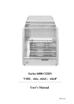
2.2.7 LX / EX fan-tray front panel view
SYS Reset Switch (protected )
Power On LED
Main Switch ON/OFF; Trip off Rest
Status LEDs:
Green Status
Yellow Fan Fail
Yellow Over Heat
Red
SYS Fail
Alphanumeric Display
MODE SELECT Switch
Fan SPEED Switch and LED
AUTO OFF Switch and LED
Network ADDRess Switch
LOCAL Switch and LED
Ethernet
RS232
EX RJ45
(standard) CANbus
CANbus
CANbus connector 1 female
LX Sub D (optional)
CANbus connector 2 male
January 15
14
*00501.A4
User’s Manual
VME 6021-23 VXI
W-Ie–Ne-R
Plein & Baus GmbH
Standard Measurement Ranges
Available Modes and Display Examples
Mode
Monitored
Values
Description
+5V
5.00 V
115A.... 230A (460)
+5V channel
+12V
12.0 V
11.5 / 46.0A (92)
+12V channel
+15V 1
15.0 V
11.5 / 35.0A (70)
+15V channel
1
24.0 V
11.5 / 23,0 A (66)
+15V channel
3.30 V
115.... 230A (460)
3,3V channel
48,0 V
13,5... 67A
-5V
5.20 V
100A.... 400A
-5.2V channel
-12V
12.0 V
6.0 / 10.0 / 40.0A (80)
-12V channel
-15V 1
15.0 V
6.0 / 10.0 / 30.0A (80)
-15V channel
1
24.0 V
6.5 / 20,0A (80)
-24V channel
2.00 V
100.0A.... 200A
-2V channel
POWER
135
W
output power
FANS
3000
RPM
fan rotation speed
FAN TEMP
25
° C or °F
fan air inlet temp.
FAN TIME
82000,6
h
Operating hours Fan tray
P.S. TIME
150000,0
h
Operating hours Power Supply
35°C
° C or °F
bin slot 1 (?) temp.
° C or °F
bin slot 2 (?) temp.
° C or °F
bin slot 8 (?) temp.
+24V
+3,3V
+48V
-24V
1
-2V
Options
BIN TEMP 1
BIN TEMP 2
....... up to
BIN TEMP 8
Networks *
CAEN*
ADDR
99
CAENET address
BAUD*
RATE
1 MBAUD
CANbus bit rate
CANbus*
ADDR
127
CANbus address
IEC*
ADDR
25
IECbus address
TCP/IP
ADDR
Details see 2.2 ++
1
Either the 15V-, the 24V- or the 48V- output will be in use, depending on the application (VME, VME64x,
VXI)
January 15
15
*00501.A4
User’s Manual
VME 6021-23 VXI
W-Ie–Ne-R
Plein & Baus GmbH
3
6021-6023 Bin Technical details
3.1.1 VME-Bus Terminology, Signal Identification
BR0*-BR3*
Bus request (0-3). Open-collector driven signals generated by
requesters. A low level on one of these lines indicates that some
master need to use the DTB
D00-D31
Data bus. Three-state driven bi-directional lines used to
transfer data between masters an slaves, and status/ID
information from interrupters to interrupt handlers.
DS0*, DS1*
Data strobe zero, one. Three-state driven signals used in
conjunction with LWORD* and A01 to indicate how many
byte locations are being accessed (1, 2, 3, or 4). In addition,
during a write cycle, the falling edge of the first data strobe
indicates that valid data is available on the data bus. On a read
cycle, the rising edge of the first data strobe indicates that data
has been accepted from the data bus.
DTACK*
Data transfer acknowledge. An open-collector driven signal
generated by a SLAVE. The falling edge of this signal indicates
that valid data is available on the data bus during a read cycle,
or that data has been accepted from the data bus during a write
cycle. The rising edge indicates when the slave has released the
data bus at the end of a read cycle.
GND
the dc voltage reference for the system
IACK*
interrupt acknowledge. An open-collector or three-state driven
signal used by an interrupt handler to acknowledge an interrupt
request. It is routed, by way of a backplane signal trace, to the
IACKIN* pin of slot 1, where it is monitored by the IACK
daisy-chain driver.
IACKIN*
interrupt acknowledge in. A totem-pole driven signal. The
IACKIN* and IACKOUT* signal indicates to the board
receiving it that it is allowed to respond to the interrupt
acknowledge cycle that is in progress.
IACKOUT*
Interrupt acknowledge out. A totem-pole driven signal. The
IACKIN* and IACKOUT* signal is sent by a board to indicate
to the next board in the daisy-chain that it is allowed to respond
the interrupt acknowledge cycle that is in progress.
IRQ1*-IRQ7*
Interrupt request (1-7). Open-collector driven signals, that are
driven low by interrupters to request an interrupt. When several
lines are monitored by a single handler the highest numbered
line is given the highest priority.
LWORD*
Longword. A three-state driven signal used in conjunction with
DS0*, DS1*, and A01 to select which byte location(s) within
the 4-byte group are accessed during the data transfer.
RESERVED
Reserved. A signal line reserved for future enhancements.
SERCLK
Serial clock. A totem-pole driven signal that is used to
synchronize the data transmission on the VMSbus.
January 15
16
*00501.A4
User’s Manual
W-Ie–Ne-R
VME 6021-23 VXI
Plein & Baus GmbH
SERDAT*
Serial data. An open collector driven signal that is used for
VMEbus data transmission.
SYSCLK
System clock. A totem-pole driven signal that provides a
constant 16 MHz clock signal that is independent of any other
bus timing.
SYSFAIL*
System reset. An open-collector driven signal that indicates
when a failure has occurred in the system. This signal can be
generated by any board in the system.
SYSRESET*
System reset. An open-collector driven signal, which when
low, causes the system to be reset.
WRITE*
Write. A three-state driven signal generated by the master to
indicate whether the data transfer cycle is a read or write. A
high level indicates a read operation; a low level indicates a
write operation.
+ 5 V STDBY
+ 5V dc standby. This line supplies 5 V dc to devices requiring
battery backup.
+ 5V
+ 5 V dc power. Used by system logic circuits.
+ 12 V
+ 12 V dc power. Used by system logic circuits.
- 12 V
- 12 V dc power. Used by system logic circuits.
3.1.2 Backplane Current Ratings
Power distribution
VME
VME
VME
VME 430
VME 64x
each slot (20°C /
70°C)
J1
J2
J1-J2
J1-Jaux-J2
J1
3,3V
17/12A
5V
9,5/7,5A
+/-12V
3,2/2,5A
9,5/7,5A
19/15A
19/15A
8,5/6A
3,2/2,5A
3,2/2,5A
1,7/1,2A
+/-15V
3,2/2,5A
-5,2V
19/15A
-2V
9,5/7,5A
Vw, Vx, Vy, Vz
V1, V2
1,7/1,2A
Layers
8
Type of ADC
mech
Termination on board
passive
J2 with 160pin
Power Connections
January 15
Studs
4
8
8
10
mech
mech
active
passive
passive
passive
active
optional
optional
optional
Studs
Studs
Studs
17
Bugs
*00501.A4
User’s Manual
W-Ie–Ne-R
VME 6021-23 VXI
Plein & Baus GmbH
Backplane Current ratings cont.
Power distribution
VME 64x
VME64xP
VXI C size
VXI D size
each slot (20°C /
70°C)
J1-Jo-J2
J1-Jo-J2
Slot 2- 212)1
J1-J2
J1-J2-J3
3,3V
17/12A
17/12A
5V
15,3/10,8A
27/19A
14/10,5A
24/18A
+/-12V
1,7/1,2A
1,7/1,2A
2/1,5A
4/3A
-5,2V
10/7,5A
20/15A
-2V
4/3A
10/7,5A
+/-24V
2/1,5A
4/3A
+/-15V
Vw, Vx, Vy, Vz
4/3A
4/3A
V1, V2
1,7/1,2A
1,7/1,2A
Layers
10
18
10
10
Type of ADC
active
active
active
active
Termination on board
active
active
active
active
Power Connections
Bugs
Bugs
Studs
Studs
3.1.3 Pin Assignment Jaux of VME 430-Bus (CERN)
Pin Number
Row A
Row B
Row C
01
SN1
GND
SN2
02
SN3
GND
SN4
03
SN5
GND
GND
04
CK*
GND
CK
05
SG*
GND
SG
06
CL*
GND
CL
07
-2 V
-2 V
-2 V
08
- 15 V
CE
+ 15 V
09
- 5,2 V
-5,2 V
- 5,2V
10
- 5,2 V
- 5,2 V
- 5,2V
2
On slot 1 of the 64xP backplane the Jo is not feeding additional 5V pins. Therefore the current capability
for +5V is only 15,3/10,8A.
January 15
18
*00501.A4
User’s Manual
W-Ie–Ne-R
VME 6021-23 VXI
Plein & Baus GmbH
3.1.3.1
Terminology and Signal Identification of Jaux
SN1... SN5, Binary coded slot No. lines, Geographical address
Slot Number
SN1
SN2
SN3
SN4
SN5
01
NC
GND
GND
GND
GND
02
GND
NC
GND
GND
GND
03
NC
NC
GND
GND
GND
04
GND
GND
NC
GND
GND
05
NC*
GND
NC
GND
GND
06
GND
NC
NC
GND
GND
19
NC
NC
GND
GND
NC
20
GND
GND
NC
GND
NC
21
NC
GND
NC
GND
NC
NC = No Connection (represents H- level, generated by 5k6 resistor on VME modul for TTL, e.g.)
CK, SG and CL signals, Clean Earth
CK, Clock signal, bussed differential line terminated on both sides of the backplane (2 resistors to
ground and 1 resistor in between the two lines according to the impedance .
CK
CK*
positive logic
negative logic
SG, Start / Stop Gate, bussed differential line terminated like CK lines.
SG
SG*
positive logic
negative logic
CL, Clear, bussed differential line terminated like CK lines.
CL
CL*
positive logic
negative logic
CE, Clean Earth , unbussed line without termination.
January 15
19
*00501.A4
User’s Manual
W-Ie–Ne-R
VME 6021-23 VXI
Plein & Baus GmbH
3.1.4 Pin Assignments of J1 and J2 VME Bus
J1
Pin
J2
Row A
Row B
Row C
Row A
Row B
Row C
01
D00
BBSY*
D08
User defined +5 V
User defined
02
D01
BCLR
D09
User defined GND
User defined
03
D02
ACFAIL*
D10
User defined Reserved
User defined
04
D03
BG0IN*
D11
User defined A24
User defined
05
D04
BG0OUT*
D12
User defined A25
User defined
06
D05
BG1IN*
D13
User defined A26
User defined
07
D06
BG1OUT*
D14
User defined A27
User defined
08
D07
BG2IN*
D15
User defined A28
User defined
09
GND
BG2OUT*
GND
User defined A29
User defined
10
SYSCLK
BG3IN*
SYSFAIL*
User defined A30
User defined
11
GND
BG3OUT*
BERR*
User defined A31
User defined
12
DS1*
BR0*
SYSRESET*
User defined GND
User defined
13
DS0*
BR1*
LWORD*
User defined +5 V
User defined
14
WRITE*
BR2*
AM5
User defined D16
User defined
15
GND
BR3*
A23
User defined D17
User defined
16
DTACK*
AM0
A22
User defined D18
User defined
17
GND
AM1
A21
User defined D19
User defined
18
AS*
AM2
A20
User defined D20
User defined
19
GND
AM3
A19
User defined D21
User defined
20
IACK*
GND
A18
User defined D22
User defined
21
IACKIN*
SERCLK
A17
User defined D23
User defined
22
IAOUT*
SERDAT
A16
User defined GND
User defined
23
AM4
GND
A15
User defined D24
User defined
24
A07
IRQ7*
A14
User defined D25
User defined
25
A06
IRQ6*
A13
User defined D26
User defined
26
A05
IRQ5*
A12
User defined D27
User defined
27
A04
IRQ4*
A11
User defined D28
User defined
28
A03
IRQ3*
A10
User defined D29
User defined
29
A02
IRQ2*
A09
User defined D30
User defined
30
A01
IRQ1*
A08
User defined D31
User defined
31
-12 V
+5V STDBY
+ 12 V
User defined GND
User defined
32
+5 V
+5V
+5V
User defined + 5 V
User defined
No.
January 15
20
*00501.A4
User’s Manual
W-Ie–Ne-R
VME 6021-23 VXI
Plein & Baus GmbH
3.1.5 Pin Assignments of VME 64x-Bus
J1 (extended)
Pin No.
Row Z
Row A
Row B
Row C
Row D
01
MPR
D00
BBSY*
D08
VPC (1)
02
GND
D01
BCLR*
D09
GND (1)
03
MCLK
D02
ACFAIL*
D10
+V1
04
GND
D03
BG0IN*
D11
+V2
05
MSD
D04
BG0OUT*
D12
RsvU
06
GND
D05
BG1IN*
D13
-V1
07
MMD
D06
BG1OUT
D14
-V2
08
GND
D07
BG2IN*
D15
RsvU
09
MCTC
GND
BG2OUT*
GND
GAP*
10
GND
SYSCLK
BG3IN*
SYSFAIL*
GAO*
11
RESP*
GND
BG3OUT*
BERR*
GA1*
12
GND
DS1*
BR0*
SYSRESET*
+3.3V
13
RsvBus
DS0*
BR1*
LWORD
GA2*
14
GND
WRITE*
BR2*
AM5
+3.3V
15
RsvBus
GND
BR3*
A23
GA3*
16
GND
DTACK*
AM0
A22
+3.3V
17
RsvBus
GND
AM1
A21
GA4*
18
GND
AS*
AM2
A20
+3.3V
19
RsvBus
GND
AM3
A19
RsvBus
20
GND
IACK*
GND
A18
+3.3V
21
RsvBus
IACKIN*
SERCLK
A17
RsvBus
22
GND
IAOUT*
SERDAT
A16
3.3V
23
RsvBus
AM4
GND
A15
RsvBus
24
GND
A07
IRQ7*
A14
+3.3V
25
RsvBus
A06
IRQ6*
A13
RsvBus
26
GND
A05
IRQ5*
A12
+3.3V
27
RsvBus
A04
IRQ4*
A11
LI/I*
28
GND
A03
IRQ3*
A10
+3.3V
29
RsvBus
A02
IRQ2*
A09
LI/O*
30
GND
A01
IRQ1*
A08
+3.3V
31
RsvBus
-12 V
+5V STDBY
+12 V
GND (1)
32
GND
+5 V
+5V
+5V
VPC (1)
January 15
21
*00501.A4
User’s Manual
W-Ie–Ne-R
VME 6021-23 VXI
Plein & Baus GmbH
J2 (extended)
Pin No.
Row Z
Row A
Row B
Row C
Row D
01
User defined
User defined
+5 VAC
User defined
User defined(1)
02
GND
User defined
GND
User defined
User defined(1)
03
User defined
User defined
RESERVED
User defined
User defined
04
GND
User defined
A24
User defined
User defined
05
User defined
User defined
A25
User defined
User defined
06
GND
User defined
A26
User defined
User defined
07
User defined
User defined
A27
User defined
User defined
08
GND
User defined
A28
User defined
User defined
09
User defined
User defined
A29
User defined
User defined
10
GND
User defined
A30
User defined
User defined
11
User defined
User defined
A31
User defined
User defined
12
GND
User defined
GND
User defined
User defined
13
User defined
User defined
+5 V
User defined
User defined
14
GND
User defined
D16
User defined
User defined
15
User defined
User defined
D17
User defined
User defined
16
GND
User defined
D18
User defined
User defined
17
User defined
User defined
D19
User defined
User defined
18
GND
User defined
D20
User defined
User defined
19
User defined
User defined
D21
User defined
User defined
20
GND
User defined
D22
User defined
User defined
21
User defined
User defined
D23
User defined
User defined
22
GND
User defined
GND
User defined
User defined
23
User defined
User defined
D24
User defined
User defined
24
GND
User defined
D25
User defined
User defined
25
User defined
User defined
D26
User defined
User defined
26
GND
User defined
D27
User defined
User defined
27
User defined
User defined
D28
User defined
User defined
28
GND
User defined
D29
User defined
User defined
29
User defined
User defined
D30
User defined
User defined
30
GND
User defined
D31
User defined
User defined
31
User defined
User defined
GND
User defined
GND (1)
32
GND
User defined
+5 V
User defined
VPC (1)
January 15
22
*00501.A4
User’s Manual
W-Ie–Ne-R
VME 6021-23 VXI
Plein & Baus GmbH
3.1.5.1
Pin Assignment Jo of VME 64x-Bus
J0 (extended)
Pos
Row f
Row e
Row d
Row c
Row b
Row a
Row z
1
GND
User
defined
User
defined
User
defined
User
defined
User
defined
GND
2
GND
User
defined
User
defined
User
defined
User
defined
User
defined
GND
3
GND
User
defined
User
defined
User
defined
User
defined
User
defined
GND
4
GND
User
defined
User
defined
User
defined
User
defined
User
defined
GND
5
GND
User
defined
User
defined
User
defined
User
defined
User
defined
GND
6
GND
User
defined
User
defined
User
defined
User
defined
User
defined
GND
7
GND
User
defined
User
defined
User
defined
User
defined
User
defined
GND
8
GND
User
defined
User
defined
User
defined
User
defined
User
defined
GND
9
GND
User
defined
User
defined
User
defined
User
defined
User
defined
GND
10
GND
User
defined
User
defined
User
defined
User
defined
User
defined
GND
11
GND
User
defined
User
defined
User
defined
User
defined
User
defined
GND
12
GND
User
defined
User
defined
User
defined
User
defined
User
defined
GND
13
GND
User
defined
User
defined
User
defined
User
defined
User
defined
GND
14
GND
User
defined
User
defined
User
defined
User
defined
User
defined
GND
15
GND
User
defined
User
defined
User
defined
User
defined
User
defined
GND
16
GND
User
defined
User
defined
User
defined
User
defined
User
defined
GND
17
GND
User
defined
User
defined
User
defined
User
defined
User
defined
GND
18
GND
User
defined
User
defined
User
defined
User
defined
User
defined
GND
19
GND
User
defined
User
defined
User
defined
User
defined
User
defined
GND
January 15
23
*00501.A4
User’s Manual
W-Ie–Ne-R
VME 6021-23 VXI
Plein & Baus GmbH
3.1.6 Pin Assignment J0 of VME 64xC –Bus
The VME64xC Bus consists of a monolythic VME64x J1/J2 bus with a special J0 high power
distribution bus. The J0 connector is built out of three 10-pin connectors MP2-HP10-51P1-TR
(Robinson Nugent) for each slot (Reference Numbers: J0.1A, J0.1B and J0.1C for slot 1, and so
on). A Current of up to 26A/slot could be supplied with each of the six UAUX lines.
Connector
Pin
J0.A
J0.B
J0.C
Signal
A1
B1
C1
D1
E1
UAUX1 (3.3V)
A2
B2
C2
D2
E2
UAUX1 Return
A1
B1
C1
D1
E1
UAUX2 (2.5V)
A2
B2
C2
D2
E2
UAUX2 Return
A1
B1
C1
D1
E1
UAUX3 (1.8V)
A2
B2
C2
D2
E2
UAUX3 Return
3.1.7 Special Pin Assignment J0 of VME 64xP - Bus (VIPA)
Some user defined pins of the 64x- Jo connector have been specified in the 64xP (VIPA) document
to get available additional voltages and signals on the backplane. The slot 1 pin out is identical to
those of the Jo of the 64x pin assignment. Slot 2 to 21 are outfitted with the following pin out:
Jo Slot 2-21
Pin No.
Row z
Row a
Row b
Row c
Row d
Row e
Row f
01
COM
+5V
+5V
+5V
+5V
+5V
COM
02
COM
RET_WX
Reserved
+5V
TBUS1+
TBUS1-
COM
03
COM
RET_WX
Reserved
Reserved
TBUS2+
TBUS2-
COM
04
COM
Vw
Reserved
USER I/O USER I/O
USER I/O
COM
05
COM
Vw
Reserved
USER I/O USER I/O
USER I/O
COM
06
COM
RET_WX
Reserved
USER I/O USER I/O
USER I/O
COM
07
COM
AREF_WX
Reserved
USER I/O USER I/O
USER I/O
COM
08
COM
RET_WX
Reserved
USER I/O USER I/O
USER I/O
COM
09
COM
Vx
Reserved
USER I/O USER I/O
USER I/O
COM
10
COM
Vx
Reserved
USER I/O USER I/O
USER I/O
COM
11
COM
Vy
Reserved
USER I/O USER I/O
USER I/O
COM
12
COM
Vy
Reserved
USER I/O USER I/O
USER I/O
COM
13
COM
RET_YZ
Reserved
USER I/O USER I/O
USER I/O
COM
14
COM
AREF_YZ
Reserved
USER I/O USER I/O
USER I/O
COM
15
COM
RET_YZ
Reserved
USER I/O USER I/O
USER I/O
COM
16
COM
Vz
Reserved
USER I/O USER I/O
USER I/O
COM
17
COM
Vz
Reserved
Reserved
TBUS3+
TBUS3-
COM
18
COM
RET_YZ
Reserved
Reserved
TBUS4+
TBUS4-
COM
19
COM
RET_YZ
Reserved
Reserved
TBUS_OC1
TBUS_OC2 COM
January 15
24
*00501.A4
User’s Manual
W-Ie–Ne-R
VME 6021-23 VXI
Plein & Baus GmbH
3.1.8 Pin Assignments of VXI-Bus
VXIbus J1/J2 Connector, Slot 1-13, C- and D- size
J1
J2
Pin No.
Row A
Row B
Row C
Row A
Row B
Row C
01
D00
BBSY*
D08
ECLTRG0
+5V
CLK10+
02
D01
BCLR
D09
- 2V
GND
CLK10-
03
D02
ACFAIL*
D10
ECLTRG1
RSV1
GND
04
D03
BG0IN*
D11
GND
A24
-5.2V
05
D04
BG0OUT*
D12
LBUSA00
A25
LBUSC00
06
D05
BG1IN*
D13
LBUSA01
A26
LBUSC01
07
D06
BG1OUT*
D14
-5.2V
A27
GND
08
D07
BG2IN*
D15
LBUSA02
A28
LBUSC02
09
GND
BG2OUT*
GND
LBUSA03
A29
LBUSC03
10
SYSCLK
BG3IN*
SYSFAIL*
GND
A30
GND
11
GND
BG3OUT*
BERR*
LBUSA04
A31
LBUSC04
12
DS1*
BR0*
SYSRESET*
LBUSA05
GND
LBUSC05
13
DS0*
BR1*
LWORD*
-5.2V
+ 5V
-2V
14
WRITE*
BR2*
AM5
LBUSA06
D16
LBUSC06
15
GND
BR3*
A23
LBUSA07
D17
LBUSC07
16
DTACK*
AM0
A22
GND
D18
GND
17
GND
AM1
A21
LBUSA08
D19
LBUSC08
18
AS*
AM2
A20
LBUSA09
D20
LBUSC09
19
GND
AM3
A19
-5.2V
D21
-5.2V
20
IACK*
GND
A18
LBUSA10
D22
LBUSC10
21
IACKIN*
SERCLK
A17
LBUSA11
D23
LBUSC11
22
IAOUT*
SERDAT
A16
GND
GND
GND
23
AM4
GND
A15
TTLTRG0*
D24
TTLTRG1*
24
A07
IRQ7*
A14
TTLTRG2*
D25
TTLTRG3*
25
A06
IRQ6*
A13
+5V
D26
GND
26
A05
IRQ5*
A12
TTLTRG4*
D27
TTLTRG5*
27
A04
IRQ4*
A11
TTLTRG6*
D28
TTLTRG7*
28
29
A03
IRQ3*
A10
GND
D29
GND
A02
IRQ2*
A09
RSV2
D30
RSV3
30
A01
IRQ1*
A08
MODID
D31
GND
31
-12 V
5V STDBY
+ 12 V
GND
GND
+24V
32
+5 V
+5V
+5V
SUMBUS
+ 5V
-24V
January 15
25
*00501.A4
User’s Manual
W-Ie–Ne-R
VME 6021-23 VXI
Plein & Baus GmbH
VXIbus J2 Connector, Slot 1, C- and D- size
Pin Number
Row A
Row B
Row C
01
ECLTRG0
+ 5 VDC
CLK10+
02
- 2V
GND
CLK10-
03
ECLTRG1
RSV1
GND
04
GND
A24
-5.2V
05
MODID12
A25
LBUSC00
06
MODID11
A26
LBUSC01
07
-5.2V
A27
GND
08
MODID10
A28
LBUSC02
09
MODID09
A29
LBUSC03
10
GND
A30
GND
11
MODID08
A31
LBUSC04
12
MODID07
GND
LBUSC05
13
-5.2V
+ VDC
-2V
14
MODID06
D16
LBUSC06
15
MODID05
D17
LBUSC07
16
GND
D18
GND
17
MODID04
D19
LBUSC08
18
MODID03
D20
LBUSC09
19
-5.2V
D21
-5.2V
20
MODID02
D22
LBUSC10
21
MODID01
D23
LBUSC11
22
GND
GND
GND
23
TTLTRG0*
D24
TTLTRG1*
24
TTLTRG2*
D25
TTLTRG3*
25
+5V
D26
GND
26
TTLTRG4*
D27
TTLTRG5*
27
TTLTRG6*
D28
TTLTRG7*
28
GND
D29
GND
29
RSV2
D30
RSV3
30
MODID
D31
GND
31
GND
GND
+24V
32
SUMBUS
+ 5VDC
-24V
January 15
26
*00501.A4
User’s Manual
VME 6021-23 VXI
W-Ie–Ne-R
Plein & Baus GmbH
VXIbus J3 Connector, Slot 2-13, D- size only
Pin Number
Row A
Row B
Row C
01
ECLTRG2
+24V
+12V
02
GND
-24V
-12V
03
ECLTRG3
GND
RSV4
04
-2V
RSV5
+5V
05
ECLTRG4
-5.2V
RSV6
06
GND
RSV7
GND
07
ECLTRG5
+5V
-5.2V
08
-2V
GND
GND
09
LBUSA12
+5V
LBUSC12
10
LBUSA13
LBUSC15
LBUSC13
11
LBUSA14
LBUSA15
LBUSC14
12
LBUSA16
GND
LBUSC16
13
LBUSA17
LBUSC19
LBUSC17
14
LBUSA18
LBUSA19
LBUSC18
15
LBUSA20
+5V
LBUSC20
16
LBUSA21
LBUSC23
LBUSC21
17
LBUSA22
LBUSA23
LBUSC22
18
LBUSA24
-2V
LBUSC24
19
LBUSA25
LBUSC27
LBUSC25
20
LBUSA26
LBUSA27
LBUSC26
21
LBUSA28
GND
LBUSC28
22
LBUSA29
LBUSC31
LBUSC29
23
LBUSA30
LBUSA31
LBUSC30
24
LBUSA32
+5V
LBUSC32
25
LBUSA33
LBUSC35
LBUSC33
26
LBUSA34
LBUSA35
LBUSC34
27
GND
GND
GND
28
STARX+
-5.2V
STARY+
29
STARX-
GND
STARY-
30
GND
-5.2V
-5.2V
31
CLK100+
-2V
SYNC100+
32
CLK100-
GND
SYNC100-
January 15
27
*00501.A4
User’s Manual
VME 6021-23 VXI
W-Ie–Ne-R
Plein & Baus GmbH
VXIbus J3 Connector, Slot 1, D- size only
Pin Number
Row A
Row B
Row C
01
ECLTRG2
+24V
+12V
02
GND
-24V
-12V
03
ECLTRG3
GND
RSV4
04
-2V
RSV5
+5V
05
ECLTRG4
-5.2V
RSV6
06
GND
RSV7
GND
07
ECLTRG5
+5V
-5.2V
08
-2V
GND
GND
09
STARY12+
+5V
STARX01+
10
STARY12-
STARY01-
STARX01-
11
STARX12+
StARX12-
STARY01+
12
STARY11+
GND
STARX02+
13
STARY11-
STARY02-
STARX02-
14
STARX11+
STARX11-
STARY02+
15
STARY10+
+5V
STARX03+
16
STARY10-
STARY03-
STARX03-
17
STARX10+
STARX10-
STARY03+
18
STARY09+
-2V
STARX04+
19
STARY09-
STARY04-
STARX04-
20
STARX09+
STARX09-
STARY04+
21
STARY08+
GND
STARX05+
22
STARY08-
STARY05-
STARX05-
23
STARX08+
STARX08-
STARY05+
24
STARY07+
+5V
STARX06+
25
STARY07-
STARY06-
STARX06-
26
STARX07+
STARY07-
STARY06+
27
GND
GND
GND
28
STARX+
-5.2V
STARY+
29
STARX-
GND
STARY-
30
GND
-5.2V
-5.2V
31
CLK100+
-2V
SYNC100+
32
CLK100-
GND
SYNC100-
January 15
28
*00501.A4
User’s Manual
W-Ie–Ne-R
VME 6021-23 VXI
Plein & Baus GmbH
18
U2
15
12
Ret.
17
14
U7
9
6
.
Ret.
-
11
8
5
Ret.
Ret.
Ext.
Res.
3
+
2
Ret.
U6
U5
U1
U3
U4
U0
16
13
10
7
4
1
Ret.
Ret.
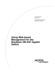
Pin 10,11,13...18:
Pin 1...9+12:
Ret.
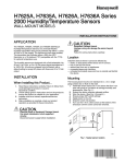
37
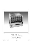
Power Connector Board (Round Contacts)
9
4.1
D-SUB 37
Power Supply UEP6021
D-SUB 9
4
Ret.
6mm, 120A max.
8mm, 240A max
Return from common ground rail at backplane
Voltages and Pin outs in Standard VME application
U0
5V (2... 7V) < 230A
U1
U2
+15V (7... 24V) < 92A
U3
+12V (7... 24V) < 92A
3,3V (2... 7V) < 230A
U4
-5,2V (2... 7V) < 230A
U5
-12V (7... 24V) < 92A
U6
-15V (7... 24V) < 92A
U7
-2V (2... 7V) < 115A
Voltages and Pin outs in Standard VME64x application
U0
U2
5V (2... 7V) < 230A
U1
+48V (30... 60V) < 92A
U4
U6
-15V (7... 24V) < 92A
U3
+12V (7... 24V) < 92A
3,3V (2... 7V) < 230A
U5
-12V (7... 24V) < 92A
U7
Voltages and Pin outs in Standard VXI application
U0
5V (2... 7V) < 230A
U1
+12V (7... 24V) < 92A
U2
+24V (12... 30V) < 92A
U3
U4
-5,2V (2... 7V) < 230A
U5
-12V (7... 24V) < 92A
U6
-24V (12... 30V) < 92A
U7
-2V (2... 7V) < 115A
January 15
29
*00501.A4
User’s Manual
VME 6021-23 VXI
W-Ie–Ne-R
Plein & Baus GmbH
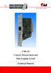
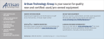
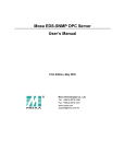
4.1.1 Sense and Signal Connector-SUB D 37
19
TEMP RETURN
37
TEMP 0
18
TEMP 1
36
TEMP 2
17
TEMP 3
35
TEMP 4
16
TEMP 5
34
TEMP 6
15
TEMP 7
33
BIN EEPROM: IIC SDA
14
BIN EEPROM: IIC SCL
32
BIN EEPROM:+5V
13
VME LOGIC: SYSRESET
31
BIN EEPROM: GND
12
VME LOGIC: ACFAIL
30
VME LOGIC GND
11
VME LOGIC: SYSFAIL
29
U0 SENSE -
10
U0 SENSE + (VME: +5V)
28
VW SENSE (reserved)
9
VW SENSE (reserved)
27
VX SENSE (reserved)
8
VX SENSE (reserved)
26
U4 SENSE +
7
U4 SENSE -
25
U7 SENSE +
6
U7 SENSE -
24
U2 SENSE -
5
U2 SENSE + (VME: 48V)
23
U6 SENSE +
4
U6 SENSE -
22
U1 SENSE -
3
U1 SENSE + (VME: +12V)
21
U5 SENSE +
2
U5 SENSE – (VME: -12V)
20
U3 SENSE -
1
U3 SENSE + (VME: +3.3V)
5
CAN_H
4.1.2 Fan tray and Control Connector SUB D9
9
CAN_L
4
CAN GND
8
RXD
3
TXD
7
+15V (for fan only)
2
+15V (for fan only)
6
-15V (for fan only)
1
-15V (for fan only)
The CANbus Logic is an option. Data exchange between fan tray and power supply has
been done by use of serial connection via RXD and TXD.
January 15
30
*00501.A4
User’s Manual
VME 6021-23 VXI
W-Ie–Ne-R
Plein & Baus GmbH
4.2
Control and Adjustment of 6021 Power Supply
Control of the Power Supply 6021 via CAN-Bus (optional)
The CAN Bus Signals are provided on the 9 Pin DSUB situated at the power box:
CAN_H:
Pin 5
CAN_L:
Pin 9
CAN_GND:
Pin 4
The software protocol is described in a separate document (Part No *00183)
CANbus is an independent port. It may be used to operate the power supply separately or in
combination with the fan tray inside the bin
Control of the Power Supply 6021 without PC or Control panel (display)
There is a on/off input and a status output function .
Remote On:
9 Pin DSUB: Close a “make” contact or switch between Pin 8 (Serial Data
In, RXD) and Pin 2 or 7.
Status Output: 9 Pin DSUB: Connect a LED between Pin 3 (Serial Data Out, TXD) and Pin
1 or 6.
Control of the Power Supply 6021 via Fan tray
Many power supply parameters may be changed via the alphanumeric control of the
connected fan tray.
The general procedure is:
- Hold the POWER and MODE switches up simultaneously until the display shows „Config:
Wait....“ and „Config: Ready !“. Then release both switches.
- Follow the instructions given above below 2.2.4
- After finishing the parameter programming, leave the submenu or configuration menu
(POWER switch down).
January 15
31
*00501.A4
User’s Manual
W-Ie–Ne-R
VME 6021-23 VXI
Plein & Baus GmbH
Table 1 List of manual Programming Features
Mode
associated parameter
submenu
Any
Voltage Ilim
(e.g. +5V or U0)
Uadj
Power
Description
Output Current limit
Output voltage fine adjustment. The same
function as the switches in the power supply
Unom
Output voltage coarse adjustment.
Imax
Monitoring: Maximum current for good
status.
Umin
Monitoring: Minimum voltage for good
status.
Umax:
Monitoring: Maximum voltage for good
status.
Auto Power On
Automatic switch on of the power supply after
come back of the mains
No Auto Power On
Switch Off Normal
Switch Off Delay
Delayed switch off: You have to push the
POWER switch down for 5 seconds until the
power supply switches off
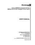
4.2.1 Connection of a Personal Computer to the Power Supply UEP6021
This connection is intended to service functions only. Because of the direct connection
between the PC and the power supply, the ripple and noise of the outputs will increase!
Requirements are a PC running Windows, the control program UEP6 and a simple adapter
(“Dongle”). The power supply is connected to the COM port of the PC. For more details,
view the document *00461.A0.
X3, 9 Pin DSUB
male (UEP6)
9 Pin DSUB female
(PC)
3
2
8
3
7
1 kOhm
5
6
1 kOhm
100nF
January 15
32
*00501.A4
User’s Manual
VME 6021-23 VXI
W-Ie–Ne-R
Plein & Baus GmbH
4.2.2 Output Voltage Adjustments
All output voltages can be adjusted manually via the two rotary switches situated on the power
supply top. Note that the status window with the programmed Umax and Umin level should be set
accordingly. Otherwise the unit will trip off if one of these levels exceed. Normally this procedure
is used if some fine adjustments becomes necessary, otherwise it is recommended to use the fan
tray switches or the remote control.
Channel selection
(0:Uo...7:U7)
Adjustment
+
4.3
Mode Selection
Function
0-7
Adjust Voltage of U0-U7
A
CAN Address (low, Bit 0-3)
B
CAN Address (high, Bit 4-6)
C
CAN General Call Address (low, Bit 0-3)
D
CAN General Call Address (high, Bit 4-6)
E
CAN Transmission Speed Index
CANbus
For software protocol see separate manual No. *00183
5
Ethernet Remote Monitoring and Control
All WIENER crates with Ethernet ports allow simple monitoring and control via a web browser
which shows status as well as all supply voltages, fan speed and temperatures. It is possible to
switch the crate on or off, send a system Reset (VME: SYSRES) and change the fan speed within
the web browser window. All active controls as on/off and change fan speed will require a user
name and password. The user name is “private” and default password also “private” (can be
changed via SNMP).
January 15
33
*00501.A4
User’s Manual
VME 6021-23 VXI
W-Ie–Ne-R
Plein & Baus GmbH
The network configuration as IP address (0.0.0.0 default = DHCP), net mask and ports can be
changed via the front panel display and switches or in case the crate is outfitted with USB port with
the WIENER MUSEcontrol program.
For full control of crate and power supply parameters or to implement the crate into a slow
control system WIENER is providing a SNMPv2c (Simple Network Management
Protocol) compliant protocol. We suggest NetSNMP as an open source SNMP program
which will be used in the further description. Please see http://net-snmp.sourceforge.net/
for more details.
5.1
SNMP communication protocol
Please download and install netSNMP (32-bit version!!! can be downloaded from
file.wiener-d.com) on the control computer. In order to perform SNMP calls from any
WIENER product the WIENER-CRATE-MIB.TXT file must be stored somewhere on the
PC doing the calls, by default that location should be /usr/share/snmp/mibs (Windows:
C:\usr\share\snmp\mibs).
The most commonly used netsnmp calls are:
snmpwalk – returns groups of parameters / items
snmpget – returns a specific parameter (read)
snmpset – sets a specific parameter (write)
Please see the Net-snmp description and help files for detailed instructions and options. All
parameters defined for the WIENER Mpod system as well as crates and other power
supplies are contained within the WIENER-CRATE-MIB.txt file.
A fast an easy way to begin using SNMP is to use command line arguments. The command
line arguments specified in this document are based on netSNMP. The command line
syntax is the same for both windows and Linux (and MAC OSX).
For all WIENER-CRATE-MIB library calls a quick help text can be shown by using
snmptranslate -On -Td WIENER-CRATE-MIB::xxxx
January 15
34
*00501.A4
User’s Manual
W-Ie–Ne-R
VME 6021-23 VXI
Plein & Baus GmbH
Example:
snmptranslate -On -Td WIENER-CRATE-MIB::outputName
.1.3.6.1.4.1.19947.1.3.2.1.2
outputName OBJECT-TYPE
-- FROM WIENER-CRATE-MIB
-- TEXTUAL CONVENTION DisplayString
SYNTAX OCTET STRING (1..4)
DISPLAY-HINT "255a"
MAX-ACCESS read-only
STATUS current
DESCRIPTION "A textual string containing a short name of the
output. If the crate is equipped with an alphanumeric
display, this string is shown to identify a output channel."
::= { iso(1) org(3) dod(6) internet(1) private(4) enterprises(1) wiener(19947) c
rate(1) output(3) outputTable(2) outputEntry(1) 2 }
A first communication with a WIENER VME/VXI/VXS crate or PL5xx power supply can
be done using the snmpwalk to confirm the existence of the power supply at the given IP
address.
snmpwalk -Cp -Oqv -v 2c -M $path -m +WIENER-CRATE-MIB -c public $ip
with:
snmpwalk: This command will retrieve a block of information.
-v 2c: This parameters specifies which version of the SNMP to use. WIENER
devices use SNMP 2C.
-M $path: This parameter should be replaced with the path to the WIENERCRATE-MIB.txt file. It is not needed in case the default path is used.
-m +WIENER-CRATE-MIB: This parameter tells the command to look at the
WIENER-CRATE-MIB to resolve the OID name.
-c public: This specifies which community of values can be accessed.
$ip: This should be replaced with the IP address of the MPOD crate.
Example for crate with IP address 192.168.0.81:
C:\ >snmpwalk -v 2c -m +WIENER-CRATE-MIB -c public 192.168.0.81
SNMPv2-MIB::sysDescr.0 = STRING: WIENER Crate (UEP6000 2.15, UEL6000 4.18, UEL6E
-BL 1.40)
SNMPv2-MIB::sysObjectID.0 = OID: WIENER-CRATE-MIB::sysMainSwitch.0
DISMAN-EVENT-MIB::sysUpTimeInstance = Timeticks: (12935) 0:02:09.35
SNMPv2-MIB::sysContact.0 = STRING:
SNMPv2-MIB::sysName.0 = STRING:
SNMPv2-MIB::sysLocation.0 = STRING:
SNMPv2-MIB::sysServices.0 = INTEGER: 79
January 15
35
*00501.A4
User’s Manual
VME 6021-23 VXI
W-Ie–Ne-R
Plein & Baus GmbH
A list of all available parameters or sub-parameters as for instance channels can be
obtained using the command snmpwalk with the parameter “crate”. To get all parameters
use:
snmpwalk -Cp -Oqv -v 2c -M $path -m +WIENER-CRATE-MIB -c public $ip crate
example:
C:\ >snmpwalk -v 2c -m +WIENER-CRATE-MIB -c public 192.168.0.81 crate
Returns for a VME64x 6023 crate:
WIENER-CRATE-MIB::sysMainSwitch.0 = INTEGER: on(1)
WIENER-CRATE-MIB::sysStatus.0 = BITS: 80 00 mainOn(0)
WIENER-CRATE-MIB::sysVmeSysReset.0 = INTEGER: 0
WIENER-CRATE-MIB::sysHardwareReset.0 = INTEGER: 0
WIENER-CRATE-MIB::outputNumber.0 = INTEGER: 4
WIENER-CRATE-MIB::outputIndex.u0 = INTEGER: u0(1)
WIENER-CRATE-MIB::outputIndex.u1 = INTEGER: u1(2)
WIENER-CRATE-MIB::outputIndex.u3 = INTEGER: u3(4)
WIENER-CRATE-MIB::outputIndex.u5 = INTEGER: u5(6)
WIENER-CRATE-MIB::outputName.u0 = STRING: +5V0
WIENER-CRATE-MIB::outputName.u1 = STRING: +12V
WIENER-CRATE-MIB::outputName.u3 = STRING: +3V3
WIENER-CRATE-MIB::outputName.u5 = STRING: -12V
WIENER-CRATE-MIB::outputGroup.u0 = INTEGER: 0
WIENER-CRATE-MIB::outputGroup.u1 = INTEGER: 0
WIENER-CRATE-MIB::outputGroup.u3 = INTEGER: 0
WIENER-CRATE-MIB::outputGroup.u5 = INTEGER: 0
WIENER-CRATE-MIB::outputStatus.u0 = BITS: 80 outputOn(0)
WIENER-CRATE-MIB::outputStatus.u1 = BITS: 80 outputOn(0)
WIENER-CRATE-MIB::outputStatus.u3 = BITS: 80 outputOn(0)
WIENER-CRATE-MIB::outputStatus.u5 = BITS: 80 outputOn(0)
WIENER-CRATE-MIB::outputMeasurementSenseVoltage.u0 = Opaque: Float: 4.990000 V
WIENER-CRATE-MIB::outputMeasurementSenseVoltage.u1 = Opaque: Float: 11.980000 V
WIENER-CRATE-MIB::outputMeasurementSenseVoltage.u3 = Opaque: Float: 3.310000 V
WIENER-CRATE-MIB::outputMeasurementSenseVoltage.u5 = Opaque: Float: 11.990000 V
WIENER-CRATE-MIB::outputMeasurementCurrent.u0 = Opaque: Float: 1.210000 A
WIENER-CRATE-MIB::outputMeasurementCurrent.u1 = Opaque: Float: 0.090000 A
WIENER-CRATE-MIB::outputMeasurementCurrent.u3 = Opaque: Float: 0.000000 A
January 15
36
*00501.A4
User’s Manual
VME 6021-23 VXI
W-Ie–Ne-R
Plein & Baus GmbH
WIENER-CRATE-MIB::outputMeasurementCurrent.u5 = Opaque: Float: 0.040000 A
WIENER-CRATE-MIB::outputMeasurementTemperature.u0 = INTEGER: ok(-128)
WIENER-CRATE-MIB::outputMeasurementTemperature.u1 = INTEGER: ok(-128)
WIENER-CRATE-MIB::outputMeasurementTemperature.u3 = INTEGER: ok(-128)
WIENER-CRATE-MIB::outputMeasurementTemperature.u5 = INTEGER: ok(-128)
WIENER-CRATE-MIB::outputSwitch.u0 = INTEGER: on(1)
WIENER-CRATE-MIB::outputSwitch.u1 = INTEGER: on(1)
WIENER-CRATE-MIB::outputSwitch.u3 = INTEGER: on(1)
WIENER-CRATE-MIB::outputSwitch.u5 = INTEGER: on(1)
WIENER-CRATE-MIB::outputVoltage.u0 = Opaque: Float: 5.000000 V
WIENER-CRATE-MIB::outputVoltage.u1 = Opaque: Float: 12.000000 V
WIENER-CRATE-MIB::outputVoltage.u3 = Opaque: Float: 3.300000 V
WIENER-CRATE-MIB::outputVoltage.u5 = Opaque: Float: 12.000000 V
WIENER-CRATE-MIB::outputAdjustVoltage.u0 = INTEGER: 22
WIENER-CRATE-MIB::outputAdjustVoltage.u1 = INTEGER: 0
WIENER-CRATE-MIB::outputAdjustVoltage.u3 = INTEGER: 0
WIENER-CRATE-MIB::outputAdjustVoltage.u5 = INTEGER: 0
WIENER-CRATE-MIB::outputCurrent.u0 = Opaque: Float: 100.000000 A
WIENER-CRATE-MIB::outputCurrent.u1 = Opaque: Float: 23.000000 A
WIENER-CRATE-MIB::outputCurrent.u3 = Opaque: Float: 115.000000 A
WIENER-CRATE-MIB::outputCurrent.u5 = Opaque: Float: 23.000000 A
WIENER-CRATE-MIB::outputSupervisionBehavior.u0 = INTEGER: 1023
WIENER-CRATE-MIB::outputSupervisionBehavior.u1 = INTEGER: 1023
WIENER-CRATE-MIB::outputSupervisionBehavior.u3 = INTEGER: 1023
WIENER-CRATE-MIB::outputSupervisionBehavior.u5 = INTEGER: 1023
WIENER-CRATE-MIB::outputSupervisionMinSenseVoltage.u0 = Opaque: Float: 4.750000V
WIENER-CRATE-MIB::outputSupervisionMinSenseVoltage.u1 = Opaque: Float: 11.400000 V
WIENER-CRATE-MIB::outputSupervisionMinSenseVoltage.u3 = Opaque: Float: 3.130000V
WIENER-CRATE-MIB::outputSupervisionMinSenseVoltage.u5 = Opaque: Float: 11.400000 V
WIENER-CRATE-MIB::outputSupervisionMaxSenseVoltage.u0 = Opaque: Float: 5.250000V
WIENER-CRATE-MIB::outputSupervisionMaxSenseVoltage.u1 = Opaque: Float: 12.599999 V
WIENER-CRATE-MIB::outputSupervisionMaxSenseVoltage.u3 = Opaque: Float: 3.470000V
WIENER-CRATE-MIB::outputSupervisionMaxSenseVoltage.u5 = Opaque: Float: 12.599999 V
WIENER-CRATE-MIB::outputSupervisionMaxTerminalVoltage.u0 = Opaque: Float: 11.000000 V
WIENER-CRATE-MIB::outputSupervisionMaxTerminalVoltage.u1 = Opaque: Float: 15.000000 V
WIENER-CRATE-MIB::outputSupervisionMaxTerminalVoltage.u3 = Opaque: Float: 4.500000 V
WIENER-CRATE-MIB::outputSupervisionMaxTerminalVoltage.u5 = Opaque: Float: 15.000000 V
WIENER-CRATE-MIB::outputSupervisionMaxCurrent.u0 = Opaque: Float: 115.000000
AWIENER-CRATE-MIB::outputSupervisionMaxCurrent.u1 = Opaque: Float: 23.000000 A
WIENER-CRATE-MIB::outputSupervisionMaxCurrent.u3 = Opaque: Float: 115.000000 A
WIENER-CRATE-MIB::outputSupervisionMaxCurrent.u5 = Opaque: Float: 23.000000 A
WIENER-CRATE-MIB::outputConfigMaxSenseVoltage.u0 = Opaque: Float: 8.150000 V
WIENER-CRATE-MIB::outputConfigMaxSenseVoltage.u1 = Opaque: Float: 16.820000 V
WIENER-CRATE-MIB::outputConfigMaxSenseVoltage.u3 = Opaque: Float: 8.150000 V
WIENER-CRATE-MIB::outputConfigMaxSenseVoltage.u5 = Opaque: Float: 16.820000 V
WIENER-CRATE-MIB::outputConfigMaxTerminalVoltage.u0 = Opaque: Float: 11.000000 V
WIENER-CRATE-MIB::outputConfigMaxTerminalVoltage.u1 = Opaque: Float: 20.539999 V
WIENER-CRATE-MIB::outputConfigMaxTerminalVoltage.u3 = Opaque: Float: 10.759999 V
WIENER-CRATE-MIB::outputConfigMaxTerminalVoltage.u5 = Opaque: Float: 20.539999 V
WIENER-CRATE-MIB::outputConfigMaxCurrent.u0 = Opaque: Float: 115.000000 A
WIENER-CRATE-MIB::outputConfigMaxCurrent.u1 = Opaque: Float: 23.000000 A
WIENER-CRATE-MIB::outputConfigMaxCurrent.u3 = Opaque: Float: 115.000000 A
WIENER-CRATE-MIB::outputConfigMaxCurrent.u5 = Opaque: Float: 23.000000 A
WIENER-CRATE-MIB::sensorNumber.0 = INTEGER: 8
WIENER-CRATE-MIB::sensorTemperature.temp1 = INTEGER: -128 deg C
January 15
37
*00501.A4
User’s Manual
VME 6021-23 VXI
W-Ie–Ne-R
Plein & Baus GmbH
WIENER-CRATE-MIB::sensorTemperature.temp2 = INTEGER: -128 deg C
WIENER-CRATE-MIB::sensorTemperature.temp3 = INTEGER: -128 deg C
WIENER-CRATE-MIB::sensorTemperature.temp4 = INTEGER: -128 deg C
WIENER-CRATE-MIB::sensorTemperature.temp5 = INTEGER: -128 deg C
WIENER-CRATE-MIB::sensorTemperature.temp6 = INTEGER: -128 deg C
WIENER-CRATE-MIB::sensorTemperature.temp7 = INTEGER: -128 deg C
WIENER-CRATE-MIB::sensorTemperature.temp8 = INTEGER: -128 deg C
WIENER-CRATE-MIB::sensorWarningThreshold.temp1 = INTEGER: 45 deg C
WIENER-CRATE-MIB::sensorWarningThreshold.temp2 = INTEGER: 45 deg C
WIENER-CRATE-MIB::sensorWarningThreshold.temp3 = INTEGER: 45 deg C
WIENER-CRATE-MIB::sensorWarningThreshold.temp4 = INTEGER: 45 deg C
WIENER-CRATE-MIB::sensorWarningThreshold.temp5 = INTEGER: 45 deg C
WIENER-CRATE-MIB::sensorWarningThreshold.temp6 = INTEGER: 45 deg C
WIENER-CRATE-MIB::sensorWarningThreshold.temp7 = INTEGER: 45 deg C
WIENER-CRATE-MIB::sensorWarningThreshold.temp8 = INTEGER: 45 deg C
WIENER-CRATE-MIB::sensorFailureThreshold.temp1 = INTEGER: 127 deg C
WIENER-CRATE-MIB::sensorFailureThreshold.temp2 = INTEGER: 127 deg C
WIENER-CRATE-MIB::sensorFailureThreshold.temp3 = INTEGER: 127 deg C
WIENER-CRATE-MIB::sensorFailureThreshold.temp4 = INTEGER: 127 deg C
WIENER-CRATE-MIB::sensorFailureThreshold.temp5 = INTEGER: 127 deg C
WIENER-CRATE-MIB::sensorFailureThreshold.temp6 = INTEGER: 127 deg C
WIENER-CRATE-MIB::sensorFailureThreshold.temp7 = INTEGER: 127 deg C
WIENER-CRATE-MIB::sensorFailureThreshold.temp8 = INTEGER: 127 deg C
WIENER-CRATE-MIB::snmpCommunityName.public = STRING: "public"
WIENER-CRATE-MIB::snmpPort.0 = INTEGER: 161
WIENER-CRATE-MIB::firmwareUpdate.0 = ""
WIENER-CRATE-MIB::ipDynamicAddress.0 = IpAddress: 192.168.0.81
WIENER-CRATE-MIB::ipStaticAddress.0 = IpAddress: 192.168.0.81
WIENER-CRATE-MIB::macAddress.0 = Hex-STRING: 00 50 C2 2D C0 7B
WIENER-CRATE-MIB::communication.3.1.0 = INTEGER: 115200
WIENER-CRATE-MIB::communication.3.2.0 = INTEGER: 0
WIENER-CRATE-MIB::communication.3.3.0 = INTEGER: 8
WIENER-CRATE-MIB::communication.3.4.0 = INTEGER: 1
WIENER-CRATE-MIB::communication.3.5.0 = INTEGER: 0
WIENER-CRATE-MIB::psSerialNumber.0 = STRING: 3296019
WIENER-CRATE-MIB::psOperatingTime.0 = INTEGER: 8394120 s
WIENER-CRATE-MIB::fanSerialNumber.0 = STRING: 3096006
WIENER-CRATE-MIB::fanOperatingTime.0 = INTEGER: 33516651 s
WIENER-CRATE-MIB::fanAirTemperature.0 = INTEGER: 27 deg C
WIENER-CRATE-MIB::fanSwitchOffDelay.0 = INTEGER: 10 s
WIENER-CRATE-MIB::fanNominalSpeed.0 = INTEGER: 3000 RPM
WIENER-CRATE-MIB::fanNumberOfFans.0 = INTEGER: 3 Fans
WIENER-CRATE-MIB::fanSpeed.1 = INTEGER: 2940 RPM
WIENER-CRATE-MIB::fanSpeed.2 = INTEGER: 2910 RPM
WIENER-CRATE-MIB::fanSpeed.3 = INTEGER: 2977 RPM
WIENER-CRATE-MIB::numberOfAnalogInputs.0 = INTEGER: 0
WIENER-CRATE-MIB::digitalInput.0 = BITS: 10 00 d3(3)
WIENER-CRATE-MIB::digitalInput.0 = No more variables left in this MIB View (It is past the end
of the MIB tree)
Further it is possible obtain the array of names or values for a specific parameter. The
following command provides a list of all existing output channels:
snmpwalk -Cp -Oqv -v 2c -M $path -m +WIENER-CRATE-MIB -c public $ip
outputVoltage
January 15
38
*00501.A4
User’s Manual
VME 6021-23 VXI
W-Ie–Ne-R
Plein & Baus GmbH
Example to read output set voltages:
C:\ >snmpwalk -v 2c -m +WIENER-CRATE-MIB -c public 192.168.2.25 outputVoltage
returns for a VME64x crate:
WIENER-CRATE-MIB::outputVoltage.u0 = Opaque: Float: 5.000000 V
WIENER-CRATE-MIB::outputVoltage.u1 = Opaque: Float: 12.000000 V
WIENER-CRATE-MIB::outputVoltage.u3 = Opaque: Float: 3.300000 V
WIENER-CRATE-MIB::outputVoltage.u5 = Opaque: Float: 12.000000 V
After obtaining information about the crate / power supplies or a list of channels and
parameters, it is useful to be able to write or read particular data. This can be done using
the snmpget and snmpset commands.
snmpget -Oqv -v 2c -M $path -m +WIENER-CRATE-MIB -c public $ip name.index
snmpset -v 2c -M $path -m +WIENER-CRATE-MIB -c admin $ip name.index format
value
Via SNMP the status of the crate can be read and the crate can be switched on or off 1:
snmpget -v 2c -M $path -m +WIENER-CRATE-MIB -c public $ip sysMainSwitch.0
Example:
C:\ >snmpget -v 2c -m +WIENER-CRATE-MIB -c public 192.168.0.81 sysMainSwitch.0
WIENER-CRATE-MIB::sysMainSwitch.0 = INTEGER: OFF(0)
This indicates that the crate or power supply is currently off. To better understand the call
above we will break it down by parameter:
snmpget: This command will retrieve a value about the crate or one of the channels
it houses..
-v 2c: This parameters specifies which version of the SNMP to use. WIENER
devices use SNMP 2C.
-M $path: This parameter should be replaced with the path to the WIENERCRATE-MIB.txt file.
-m +WIENER-CRATE-MIB: This parameter tells the command to look at the
WIENER-CRATE-MIB to resolve the OID name.
-c public: This specifies which community of values can be accessed.
$ip: This should be replaced with the IP address of the crate.
sysMainSwitch.0: This is the register you wish to retrieve.
Since we know from the call above that the crate is off, we may want to turn it on.
snmpset -v 2c - path -m +WIENER-CRATE-MIB -c COMMUNITY $ip sysMainSwitch.0 i 1
The following community groups are used:
•
•
•
“public”: for all read operations
“private”: to switch crate on or off
“admin”: to change parameters as fan speed or temperature limits
In case the wrong community code is used a “not writable” error message will be received.
January 15
39
*00501.A4
User’s Manual
W-Ie–Ne-R
VME 6021-23 VXI
Plein & Baus GmbH
Most of the parameters for snmpset are the same as snmpget, the new parameters are
highlighted below.
i: Since sysMainSwitch.0 is an integer value, we specify the value to be an integer
1: This is the value we wish to write. In this case we write ‘one’ to set the main
switch to on.
Example for VME 6023 crate:
C:\ >snmpset -v 2c -m +WIENER-CRATE-MIB -c private 192.168.0.81 sysMainSwitch.0 i 1
WIENER-CRATE-MIB::sysMainSwitch.0 = INTEGER: on(1)
For most of the write commands (snmpset) the access type has to be changed from public
to private. A complete list of value names that can be written or read via SNMP can be
found in the WIENER-CRATE-MIB but commonly needed values are:
Value Name
Type
Access
Comments
sysMainSwitch.0
Integer
R/W
ON/OFF
outputVoltage.u0 … u7
float
R/W
Channel set voltage
outputCurrent.u0 … u7
float
R/W
Channel set current limit
outputMeasurementSenseVoltage.u0 … u7
float
R
Measured channel Voltage
outputMeasurementCurrent.u0 … u7
float
R
Measured channel current
sensorTemperature.temp1 … temp8
integer
R
Measured temperature for
optional sensors 1 to 8
fanAirTemperature.0
integer
R
Air inlet temperature
sensorWarningThreshold.temp1 …temp8
integer
R/W
Warning temperature limit
(switch fans to full speed)
sensorFailureThreshold.temp1 … temp8
integer
R/W
Over
temperature
limit
(switch power supply off)
fanNominalSpeed.0
integer
R/W
Set fan speed
fanSpeed.1… number of fans
integer
R
Measured speed of fan
WARNING:
Do not change the factory default settings for voltage and current parameters for WIENER
UEPxxx power supplies and or power supplies used in or for VME / VXS / VXI or NIM and
CAMAC chassis!!! Wrong settings can damage plugged in modules or other connected
electronic circuits!!!
Changing fan speed to lower values may cause insufficient cooling and can damage plugged
in modules!
Following examples are given to get information for power supply output channel u0 and
to read / program temperature limits:
Read set voltage:
C:\ >snmpget -v 2c -m +WIENER-CRATE-MIB -c public 192.168.0.81 outputVoltage.001
WIENER-CRATE-MIB::outputVoltage.u0 = Opaque: Float: 5.000000 V
January 15
40
*00501.A4
User’s Manual
W-Ie–Ne-R
VME 6021-23 VXI
Plein & Baus GmbH
Read measured voltage:
C:\Users\Andreas Ruben>snmpget -v 2c -m +WIENER-CRATE-MIB -c public 192.168.0.81
outputMeasurementSenseVoltage.u0
WIENER-CRATE-MIB::outputMeasurementSenseVoltage.u0 = Opaque: Float: 5.000000 V
Read measured current:
C:\Users\Andreas Ruben>snmpget -v 2c -m +WIENER-CRATE-MIB -c public 192.168.0.81
outputMeasurementCurrent.u0
WIENER-CRATE-MIB::outputMeasurementCurrent.u0 = Opaque: Float: 3.640000 A
Read temperatures (crate is outfitted with 3 sensors at position 4,5 and 6:
C:\ >snmpwalk -v 2c -m +WIENER-CRATE-MIB -c public 192.168.0.81 sensorTemperature
WIENER-CRATE-MIB::sensorTemperature.temp1 = INTEGER: -128 deg C
WIENER-CRATE-MIB::sensorTemperature.temp2 = INTEGER: -128 deg C
WIENER-CRATE-MIB::sensorTemperature.temp3 = INTEGER: -128 deg C
WIENER-CRATE-MIB::sensorTemperature.temp4 = INTEGER: 25 deg C
WIENER-CRATE-MIB::sensorTemperature.temp5 = INTEGER: 25 deg C
WIENER-CRATE-MIB::sensorTemperature.temp6 = INTEGER: 27 deg C
WIENER-CRATE-MIB::sensorTemperature.temp7 = INTEGER: -128 deg C
WIENER-CRATE-MIB::sensorTemperature.temp8 = INTEGER: -128 deg C
Read specific temperature probe:
C:\ >snmpget -v 2c -m +WIENER-CRATE-MIB -c public 192.168.0.81
sensorTemperature.temp4
WIENER-CRATE-MIB::sensorTemperature.temp4 = INTEGER: 25 deg C
Set temperature warning level for probe 4
C:\>snmpset -v 2c -m +WIENER-CRATE-MIB -c admin 192.168.0.81
sensorWarningThreshold.temp4 i 50
WIENER-CRATE-MIB::sensorWarningThreshold.temp4 = INTEGER: 50 deg C
Set fan speed to 3100 RPM
C:\>snmpset -v 2c -m +WIENER-CRATE-MIB -c admin 192.168.0.81fanNominalSpeed.0 i
3100
WIENER-CRATE-MIB::fanNominalSpeed.0 = INTEGER: 3100 RPM
5.2
Change of IP address via SNMP
WIENER crates with Ethernet remote monitoring can be operated either with static IP
address or in DHCP mode where the actual IP address is defined by the network router.
DHCP is selected by setting the static IP address on the fan tray front panel to 0.0.0.0.
Two SNMP ID's are used for the dynamic and static IP address:
WIENER-CRATE-MIB::ipDynamicAddress.0 = IpAddress: 192.168.0.81
WIENER-CRATE-MIB::ipStaticAddress.0 = IpAddress: 192.168.0.81
To change the Crate IP address via SNMP perform the following call (change as example
to 192.168.0.56):
snmpset -v 2c -m +WIENER-CRATE-MIB -c guru 192.168.0.81 ipStaticAddress.0 =
192.168.0.56
January 15
41
*00501.A4
User’s Manual
W-Ie–Ne-R
VME 6021-23 VXI
Plein & Baus GmbH
WIENER-CRATE-MIB::ipStaticAddress.0 = IpAddress: 192.168.0.56
5.3
Change of community names / setting of passwords
For the communication with MPOD modules 4 types of SNMP communities are used,
“public", "private" and "admin". By default the community names are equal to the community
types.
snmpwalk -v 2c -m +WIENER-CRATE-MIB -c admin 192.168.0.81 snmpCommunityName
WIENER-CRATE-MIB::snmpCommunityName.public = STRING: "public"
WIENER-CRATE-MIB::snmpCommunityName.private = STRING: "private"
WIENER-CRATE-MIB::snmpCommunityName.admin = STRING: "admin"
snmpwalk -v 2c -m +WIENER-CRATE-MIB -c private 192.168.0.81snmpCommunityName
WIENER-CRATE-MIB::snmpCommunityName.public = STRING: "public"
WIENER-CRATE-MIB::snmpCommunityName.private = STRING: "private"
In order to secure the MPOD system communication the community names can be
used as passwords and be changed accordingly. The following example shows how the
change and test the community names. Using a wrong community name will result in a
time out error. Please note, that especially the communities with write access (private,
admin) should be protected.
snmpset
-v
2c
-m
+WIENER-CRATE-MIB
snmpCommunityName.private s seCrET
-c
private
192.168.0.81
WIENER-CRATE-MIB::snmpCommunityName.private = STRING: "seCrET"
snmpwalk -v 2c -m +WIENER-CRATE-MIB -c private 192.168.0.81snmpCommunityName
Timeout: No Response from 192.168.0.80
snmpwalk -v 2c -m +WIENER-CRATE-MIB -c seCrET 192.168.0.80 snmpCommunityName
WIENER-CRATE-MIB::snmpCommunityName.public = STRING: "public"
WIENER-CRATE-MIB::snmpCommunityName.private = STRING: ""seCrET"
WIENER-CRATE-MIB::snmpCommunityName.admin = STRING: "admin"
January 15
42
*00501.A4
User’s Manual
VME 6021-23 VXI
W-Ie–Ne-R
Plein & Baus GmbH
5.4
SNMP Version 3
SNMPv3 adds security features to the SNMP protocol. The main enhancements compared to
SNMP version 2c are
-
user names instead of community names
possible authentication (to be sure the data sent from the computer to the crate and vice
versa is from an authorized user)
possible privacy (encryption to avoid the data “on the wire” can be understand/modified by
a not authorized entity)
5.4.1 Users
The SNMP v3 users are fixed and can not be changed. The name is related to the also existing
SNMP v2c communities:
- public
Read-Only access
- private
All operations allowed by direct access of the front panel (e.g.
switch on/off)
- admin
Change of supervision limits
- guru
Change of voltage/current settings (might damage electronics if
done wrong)
- wiener
This user is reserved for W-IE-NE-R tools for special setup
operations
5.4.2 Authentication
The used authentication protocol is HMAC-MD5-96 (RFC3414). The initial password
(authentication key, authKey) is “MySecret”, identical for all users.
5.4.3 Privacy (Encryption)
The used encryption protocol is CBC-DES (RFC3414). The initial password (privacy key,
privKey) is “MySecret” again, identical for all users.
5.4.4 Security Level
There are three possible security levels for each user:
- noAuthNoPriv No key for authentication or privacy required. This is similar to the
SNMPv2c protocol using users instead of communities
- authNoPriv
Use authKey for authentication, no privKey required
- authPriv
Both authKey and privKey must be supplied. This is the default
security level.
January 15
43
*00501.A4
User’s Manual
VME 6021-23 VXI
W-Ie–Ne-R
Plein & Baus GmbH
5.4.5 SNMP v3 Examples
Read sysDescr.0 with user “public”, security level “authPriv”, authentication protocol “MD5”, authentication password “MySecret”, privacy protocol “DES” and
privacy password “MySecret”:
$ snmpget -v 3 -u public -l authPriv -a MD5 -A MySecret -x DES -X MySecret 192.168.91.222 sysDescr.0
SNMPv2-MIB::sysDescr.0 = STRING: WIENER Crate (UEP6000 2.22, UEL6 4.23.2731.0, UEL6-BL 2.2733.0)
Showing the SNMPv3 user table, using the same security settings as before.
The usmUserTable summarizes all USM (user security model) relevant settings.
$ snmpwalk -v 3 -u public -l authPriv -a MD5 -A MySecret -x DES -X MySecret 192.168.91.222 usmUserTable
SNMP-USER-BASED-SM-MIB::usmUserSecurityName."..M...P.-.."."guru" = STRING: guru
SNMP-USER-BASED-SM-MIB::usmUserSecurityName."..M...P.-.."."admin" = STRING: admin
SNMP-USER-BASED-SM-MIB::usmUserSecurityName."..M...P.-.."."public" = STRING: public
SNMP-USER-BASED-SM-MIB::usmUserSecurityName."..M...P.-.."."wiener" = STRING: wiener
SNMP-USER-BASED-SM-MIB::usmUserSecurityName."..M...P.-.."."private" = STRING: private
SNMP-USER-BASED-SM-MIB::usmUserCloneFrom."..M...P.-.."."guru" = OID: SNMPv2-SMI::zeroDotZero
SNMP-USER-BASED-SM-MIB::usmUserCloneFrom."..M...P.-.."."admin" = OID: SNMPv2-SMI::zeroDotZero
SNMP-USER-BASED-SM-MIB::usmUserCloneFrom."..M...P.-.."."public" = OID: SNMPv2-SMI::zeroDotZero
SNMP-USER-BASED-SM-MIB::usmUserCloneFrom."..M...P.-.."."wiener" = OID: SNMPv2-SMI::zeroDotZero
SNMP-USER-BASED-SM-MIB::usmUserCloneFrom."..M...P.-.."."private" = OID: SNMPv2-SMI::zeroDotZero
SNMP-USER-BASED-SM-MIB::usmUserAuthProtocol."..M...P.-.."."guru" = OID: SNMP-USER-BASED-SM-MIB::usmHMACMD5AuthProtocol
SNMP-USER-BASED-SM-MIB::usmUserAuthProtocol."..M...P.-.."."admin" = OID: SNMP-USER-BASED-SM-MIB::usmHMACMD5AuthProtocol
SNMP-USER-BASED-SM-MIB::usmUserAuthProtocol."..M...P.-.."."public" = OID: SNMP-USER-BASED-SM-MIB::usmHMACMD5AuthProtocol
SNMP-USER-BASED-SM-MIB::usmUserAuthProtocol."..M...P.-.."."wiener" = OID: SNMP-USER-BASED-SM-MIB::usmHMACMD5AuthProtocol
SNMP-USER-BASED-SM-MIB::usmUserAuthProtocol."..M...P.-.."."private" = OID: SNMP-USER-BASED-SM-MIB::usmHMACMD5AuthProtocol
SNMP-USER-BASED-SM-MIB::usmUserAuthKeyChange."..M...P.-.."."guru" = ""
SNMP-USER-BASED-SM-MIB::usmUserAuthKeyChange."..M...P.-.."."admin" = ""
SNMP-USER-BASED-SM-MIB::usmUserAuthKeyChange."..M...P.-.."."public" = ""
SNMP-USER-BASED-SM-MIB::usmUserAuthKeyChange."..M...P.-.."."wiener" = ""
SNMP-USER-BASED-SM-MIB::usmUserAuthKeyChange."..M...P.-.."."private" = ""
SNMP-USER-BASED-SM-MIB::usmUserOwnAuthKeyChange."..M...P.-.."."guru" = ""
SNMP-USER-BASED-SM-MIB::usmUserOwnAuthKeyChange."..M...P.-.."."admin" = ""
SNMP-USER-BASED-SM-MIB::usmUserOwnAuthKeyChange."..M...P.-.."."public" = ""
SNMP-USER-BASED-SM-MIB::usmUserOwnAuthKeyChange."..M...P.-.."."wiener" = ""
January 15
44
*00501.A4
User’s Manual
VME 6021-23 VXI
W-Ie–Ne-R
Plein & Baus GmbH
SNMP-USER-BASED-SM-MIB::usmUserOwnAuthKeyChange."..M...P.-.."."private" = ""
SNMP-USER-BASED-SM-MIB::usmUserPrivProtocol."..M...P.-.."."guru" = OID: SNMP-USER-BASED-SM-MIB::usmDESPrivProtocol
SNMP-USER-BASED-SM-MIB::usmUserPrivProtocol."..M...P.-.."."admin" = OID: SNMP-USER-BASED-SM-MIB::usmDESPrivProtocol
SNMP-USER-BASED-SM-MIB::usmUserPrivProtocol."..M...P.-.."."public" = OID: SNMP-USER-BASED-SM-MIB::usmDESPrivProtocol
SNMP-USER-BASED-SM-MIB::usmUserPrivProtocol."..M...P.-.."."wiener" = OID: SNMP-USER-BASED-SM-MIB::usmDESPrivProtocol
SNMP-USER-BASED-SM-MIB::usmUserPrivProtocol."..M...P.-.."."private" = OID: SNMP-USER-BASED-SM-MIB::usmDESPrivProtocol
SNMP-USER-BASED-SM-MIB::usmUserPrivKeyChange."..M...P.-.."."guru" = ""
SNMP-USER-BASED-SM-MIB::usmUserPrivKeyChange."..M...P.-.."."admin" = ""
SNMP-USER-BASED-SM-MIB::usmUserPrivKeyChange."..M...P.-.."."public" = ""
SNMP-USER-BASED-SM-MIB::usmUserPrivKeyChange."..M...P.-.."."wiener" = ""
SNMP-USER-BASED-SM-MIB::usmUserPrivKeyChange."..M...P.-.."."private" = ""
SNMP-USER-BASED-SM-MIB::usmUserOwnPrivKeyChange."..M...P.-.."."guru" = ""
SNMP-USER-BASED-SM-MIB::usmUserOwnPrivKeyChange."..M...P.-.."."admin" = ""
SNMP-USER-BASED-SM-MIB::usmUserOwnPrivKeyChange."..M...P.-.."."public" = ""
SNMP-USER-BASED-SM-MIB::usmUserOwnPrivKeyChange."..M...P.-.."."wiener" = ""
SNMP-USER-BASED-SM-MIB::usmUserOwnPrivKeyChange."..M...P.-.."."private" = ""
SNMP-USER-BASED-SM-MIB::usmUserPublic."..M...P.-.."."guru" = ""
SNMP-USER-BASED-SM-MIB::usmUserPublic."..M...P.-.."."admin" = ""
SNMP-USER-BASED-SM-MIB::usmUserPublic."..M...P.-.."."public" = STRING: "Test_2014-12-21_13:52:58_6789012"
SNMP-USER-BASED-SM-MIB::usmUserPublic."..M...P.-.."."wiener" = ""
SNMP-USER-BASED-SM-MIB::usmUserPublic."..M...P.-.."."private" = ""
SNMP-USER-BASED-SM-MIB::usmUserStorageType."..M...P.-.."."guru" = INTEGER: permanent(4)
SNMP-USER-BASED-SM-MIB::usmUserStorageType."..M...P.-.."."admin" = INTEGER: permanent(4)
SNMP-USER-BASED-SM-MIB::usmUserStorageType."..M...P.-.."."public" = INTEGER: permanent(4)
SNMP-USER-BASED-SM-MIB::usmUserStorageType."..M...P.-.."."wiener" = INTEGER: permanent(4)
SNMP-USER-BASED-SM-MIB::usmUserStorageType."..M...P.-.."."private" = INTEGER: permanent(4)
SNMP-USER-BASED-SM-MIB::usmUserStatus."..M...P.-.."."guru" = INTEGER: active(1)
SNMP-USER-BASED-SM-MIB::usmUserStatus."..M...P.-.."."admin" = INTEGER: active(1)
SNMP-USER-BASED-SM-MIB::usmUserStatus."..M...P.-.."."public" = INTEGER: active(1)
SNMP-USER-BASED-SM-MIB::usmUserStatus."..M...P.-.."."wiener" = INTEGER: active(1)
SNMP-USER-BASED-SM-MIB::usmUserStatus."..M...P.-.."."private" = INTEGER: active(1)
SNMP-USER-BASED-SM-MIB::usmUserStatus."..M...P.-.."."private" = No more variables left in this MIB View (It is past the end of the MIB tree)
5.4.6 Changing the Passwords
Changing password keys with normal snmpget/snmpset commands is quite complicated, but using the snmpusm program from Net-SNMP.org makes it comfortable.
You need to know the old password to change the new password.
The best way to understand the syntax is to look at the following examples (must be executed in the correct sequence to work correct). For the full details of the
snmpusm command please look at the man page of www.net-snmp.org.
January 15
45
*00501.A4
User’s Manual
VME 6021-23 VXI
W-Ie–Ne-R
Plein & Baus GmbH
Change PRIV password with user guru for user admin from MySecret -> newsyrupA
$ snmpusm –v 3 -u guru -l authPriv -a MD5 -A MySecret -x DES -X MySecret -Cx 192.168.91.222 passwd MySecret newsyrupA admin
Change PRIV password with user guru for user guru (himself) from MySecret -> newsyrup
$ snmpusm –v 3 -u guru -l authPriv -a MD5 -A MySecret -x DES -X MySecret -Cx 192.168.91.222 passwd MySecret newsyrup
Change AUTH password with user guru for user admin from MySecret -> newsyrupA
$ snmpusm –v 3 -u guru -l authPriv -a MD5 -A MySecret -x DES -X newsyrup
-Ca 192.168.91.222 passwd MySecret newsyrupA admin
Change AUTH password with user guru for user guru (himself) from MySecret -> newsyrup
$ snmpusm –v 3 -u guru -l authPriv -a MD5 -A MySecret -x DES -X newsyrup
-Ca 192.168.91.222 passwd MySecret newsyrup
Now change AUTH and PRIV passwords together with user guru for user admin from newsyrupA -> MySecret
$ snmpusm –v 3 -u guru
-l authPriv -a MD5 -A newsyrup -x DES -X newsyrup
192.168.91.222 passwd newsyrupA MySecret admin
And finally change AUTH and PRIV passwords together with user guru for user guru (himself) from newsyrup -> MySecret
$ snmpusm –v 3 -u guru
January 15
-l authPriv -a MD5 -A newsyrup -x DES -X newsyrup
46
192.168.91.222 passwd newsyrup MySecret
*00501.A4
User’s Manual
VME 6021-23 VXI
W-Ie–Ne-R
Plein & Baus GmbH
5.4.7 Changing the Security Level
The factory default security level is set to authPriv (the strictest setting).
This setting can be retrieved and changed (relaxed) by modifying the usmUserTable. According to the SNMP-USER-BASED-SM-MIB (RFC3414) the settings can
not be changed back from usmNoAuthProtocol (or usmNoPrivProtocol) to smoething more restrictive. The only way to do this is to restore the default SNMP settings.
First get the values of the usmUserPriv protocol
$ snmpwalk -v 3 -u guru -l authPriv -a MD5 -A MySecret -x DES -X MySecret 192.168.91.222 usmUserPrivProtocol
SNMP-USER-BASED-SM-MIB::usmUserPrivProtocol."..M...P.-.."."guru" = OID: SNMP-USER-BASED-SM-MIB::usmDESPrivProtocol
SNMP-USER-BASED-SM-MIB::usmUserPrivProtocol."..M...P.-.."."admin" = OID: SNMP-USER-BASED-SM-MIB::usmDESPrivProtocol
SNMP-USER-BASED-SM-MIB::usmUserPrivProtocol."..M...P.-.."."public" = OID: SNMP-USER-BASED-SM-MIB::usmDESPrivProtocol
SNMP-USER-BASED-SM-MIB::usmUserPrivProtocol."..M...P.-.."."wiener" = OID: SNMP-USER-BASED-SM-MIB::usmDESPrivProtocol
SNMP-USER-BASED-SM-MIB::usmUserPrivProtocol."..M...P.-.."."private" = OID: SNMP-USER-BASED-SM-MIB::usmDESPrivProtocol
You need the compete OID of the usmUserPrivProtocol to access it with the snmpset command. The previous output shows only dots for some not printable OID parts
of the (textual) OID. To get the complete values, repeat the command and add the –On option:
$ snmpwalk -v 3 -u guru -l authPriv -a MD5 -A MySecret -x DES -X MySecret 192.168.91.222 -On usmUserPrivProtocol
.1.3.6.1.6.3.15.1.2.2.1.8.11.128.0.77.235.3.0.80.194.45.202.164.4.103.117.114.117 = OID: .1.3.6.1.6.3.10.1.2.2
.1.3.6.1.6.3.15.1.2.2.1.8.11.128.0.77.235.3.0.80.194.45.202.164.5.97.100.109.105.110 = OID: .1.3.6.1.6.3.10.1.2.2
.1.3.6.1.6.3.15.1.2.2.1.8.11.128.0.77.235.3.0.80.194.45.202.164.6.112.117.98.108.105.99 = OID: .1.3.6.1.6.3.10.1.2.2
.1.3.6.1.6.3.15.1.2.2.1.8.11.128.0.77.235.3.0.80.194.45.202.164.6.119.105.101.110.101.114 = OID: .1.3.6.1.6.3.10.1.2.2
.1.3.6.1.6.3.15.1.2.2.1.8.11.128.0.77.235.3.0.80.194.45.202.164.7.112.114.105.118.97.116.101 = OID: .1.3.6.1.6.3.10.1.2.2
Now we have the OIDs for the following snmpset commands.
To disable privacy for user guru, use the command
$ OID_PRIV=".1.3.6.1.6.3.15.1.2.2.1.8.11.128.0.77.235.3.0.80.194.45.202.164.4.103.117.114.117"
$ snmpset
-v 3 -u guru
-l authPriv
-a MD5 -A MySecret -x DES -X MySecret 192.168.91.222 $OID_PRIV = SNMP-USER-BASED-SM-MIB::usmNoPrivProtocol = SNMP-USERBASED-SM-MIB::usmNoPrivProtocol
SNMP-USER-BASED-SM-MIB::usmUserPrivProtocol."..M...P.-.."."guru" = OID: SNMP-USER-BASED-SM-MIB::usmNoPrivProtocol
January 15
47
*00501.A4
User’s Manual
VME 6021-23 VXI
W-Ie–Ne-R
Plein & Baus GmbH
Next do the same procedure with usmUserAuthProtocol.
First get the values of the usmUserPriv protocol
$ SNMP-USER-BASED-SM-MIB::usmUserAuthProtocol."..M...P.-.."."guru" = OID: SNMP-USER-BASED-SM-MIB::usmHMACMD5AuthProtocol
SNMP-USER-BASED-SM-MIB::usmUserAuthProtocol."..M...P.-.."."admin" = OID: SNMP-USER-BASED-SM-MIB::usmHMACMD5AuthProtocol
SNMP-USER-BASED-SM-MIB::usmUserAuthProtocol."..M...P.-.."."public" = OID: SNMP-USER-BASED-SM-MIB::usmHMACMD5AuthProtocol
SNMP-USER-BASED-SM-MIB::usmUserAuthProtocol."..M...P.-.."."wiener" = OID: SNMP-USER-BASED-SM-MIB::usmHMACMD5AuthProtocol
SNMP-USER-BASED-SM-MIB::usmUserAuthProtocol."..M...P.-.."."private" = OID: SNMP-USER-BASED-SM-MIB::usmHMACMD5AuthProtocol
You need the compete OID of the usmUserAuthProtocol to access it with the snmpset command. The previous output shows only dots for some not printable OID
parts of the (textual) OID. To get the complete values, repeat the command and add the –On option:
$ snmpwalk -v 3 -u guru -l authPriv -a MD5 -A MySecret -x DES -X MySecret 192.168.91.222 -On usmUserAuthProtocol
.1.3.6.1.6.3.15.1.2.2.1.5.11.128.0.77.235.3.0.80.194.45.202.164.4.103.117.114.117 = OID: .1.3.6.1.6.3.10.1.1.2
.1.3.6.1.6.3.15.1.2.2.1.5.11.128.0.77.235.3.0.80.194.45.202.164.5.97.100.109.105.110 = OID: .1.3.6.1.6.3.10.1.1.2
.1.3.6.1.6.3.15.1.2.2.1.5.11.128.0.77.235.3.0.80.194.45.202.164.6.112.117.98.108.105.99 = OID: .1.3.6.1.6.3.10.1.1.2
.1.3.6.1.6.3.15.1.2.2.1.5.11.128.0.77.235.3.0.80.194.45.202.164.6.119.105.101.110.101.114 = OID: .1.3.6.1.6.3.10.1.1.2
.1.3.6.1.6.3.15.1.2.2.1.5.11.128.0.77.235.3.0.80.194.45.202.164.7.112.114.105.118.97.116.101 = OID: .1.3.6.1.6.3.10.1.1.2
Now we have the OIDs for the following snmpset commands.
To disable authentication for user guru, use the command
$ OID_AUTH=".1.3.6.1.6.3.15.1.2.2.1.5.11.128.0.77.235.3.0.80.194.45.202.164.4.103.117.114.117"
$ snmpset -v 3 -u guru -l authPriv -a MD5 -A MySecret -x DES -X MySecret 192.168.91.222 $OID_AUTH = SNMP-USER-BASED-SM-MIB::usmNoAuthProtocol
SNMP-USER-BASED-SM-MIB::usmUserAuthProtocol."..M...P.-.."."guru" = OID: SNMP-USER-BASED-SM-MIB::usmNoAuthProtocol
Ready! Verify the result by doing a snmpwalk usmUserTable, or try to access a value via snmpget without authentication and privacy:
$ snmpget -v 3 -u guru -l noAuthNoPriv 192.168.91.222 sysDescr.0
SNMPv2-MIB::sysDescr.0 = STRING: WIENER Crate (UEP6000 2.22, UEL6 4.23.2731.0, UEL6-BL 2.2733.0)
January 15
48
*00501.A4
User’s Manual
VME 6021-23 VXI
W-Ie–Ne-R
Plein & Baus GmbH
5.4.8 Creating a Save System
To get a save system, the authKeys and privKeys for all users must be changed, and the passwords
must be kept confidential (don’t forget the user “wiener”).
The device EEPROM stores localized keys (if the user uses the same key for different hardware
devices, the real key used for this device is altered in a random way, using the crates MAC
address.) So if read access to one EEPROM is achieved, this does not disclose the non-localized
keys used by the operator of the system.
Then SNMPv2 access via community strings must be disabled (you might omit “public” if you
don’t want do disable read only access). This can be done by changing the community string to a
zero string (no characters, length 0). This can by done by using the following commands:
Test snmp community access (using community “private” here)
$ snmpget -v 2c -c private 192.168.91.222 sysDescr.0
SNMPv2-MIB::sysDescr.0 = STRING: WIENER Crate (UEP6000 2.22, UEL6 4.23.2731.0, UEL6-BL 2.2733.0)
Set all community strings to ""
$ snmpset -v 2c -c wiener –m +WIENER-CRATE-MIB 192.168.91.222 snmpCommunityName.public = ""
snmpCommunityName.public = ""
$ snmpset -v 2c -c wiener –m +WIENER-CRATE-MIB 192.168.91.222 snmpCommunityName.private = ""
snmpCommunityName.private = ""
$ snmpset -v 2c -c wiener –m +WIENER-CRATE-MIB 192.168.91.222 snmpCommunityName.admin = ""
snmpCommunityName.admin = ""
$ snmpset -v 2c -c wiener –m +WIENER-CRATE-MIB 192.168.91.222 snmpCommunityName.guru = ""
snmpCommunityName.guru = ""
WIENER-CRATE-MIB::snmpCommunityName.private = ""
$ snmpset -v 2c -c wiener –m +WIENER-CRATE-MIB 192.168.91.222 snmpCommunityName.5 = ""
snmpCommunityName.5 = ""
Verify. There should be no response, the community is ignored.
$ snmpget -v 2c -c private 192.168.91.222 sysDescr.0
Timeout: No Response from 192.168.91.222.
5.4.9 Restoring Factory Defaults
If authentication keys got lost, or if a lesser security level is required, the only way is to set the
device back to factory defaults.
If SNMP access is possible, use the command
$ snmpset -m +WIENER-CRATE-MIB -v 3 -u guru -l authPriv -a MD5 -A MySecret -x DES -X MySecret
192.168.91.222 sysFactoryDefaults.0 = 1
WIENER-CRATE-MIB::sysFactoryDefaults.0 = INTEGER: on(1)
January 15
49
*00501.A4
User’s Manual
VME 6021-23 VXI
W-Ie–Ne-R
Plein & Baus GmbH
If no SNMP access is possible, you have to use the switches at the fan tray front panel (see 2.2.4)
- select the “TCPIP” menu
- switch to “Configuration…” mode
- select the “SNMP Defaults” submenu
- change “No” to “Yes”
- push up (OK)
5.5
WIENER SYScontrol Software
WIENER provides a user friendly SNMP based control program SYScontrol which can be
downloaded from the file.wiener-d.com file server. SYScontrol requires NetSNMP to be installed
and the WIENER-CRATE-MIB.TXT mib file to be copied into the right directory (see 5.1).
SYScontrol allows to scan a network for WIENER chassis and power supplies in order to
determine the matching IP addresses. Further remote ON/OFF, fan control as well as setting of fan
and temperature limits is possible.
January 15
50
*00501.A4
User’s Manual
VME 6021-23 VXI
W-Ie–Ne-R
Plein & Baus GmbH
Search for WIENER devices / set IP address for crate to be monitored:
January 15
51
*00501.A4
User’s Manual
VME 6021-23 VXI
W-Ie–Ne-R
Plein & Baus GmbH
5.6
MIB Browser
There are several commercial or open source MIB-Browser programs available which can be
used for SNMP communication. These provide often a simple GUI and allow SNMP calls.
Following is a list of some free or open source MIB – browsers:
http://www.ireasoning.com/mibbrowser.shtml
http://www.serverscheck.com/mib_browser/
http://www.mibble.org/
http://www.ks-soft.net/hostmon.eng/mibbrowser/index.htm
http://www.tembria.com/products/snmpbrowser/index.html
January 15
52
*00501.A4
User’s Manual
W-Ie–Ne-R
VME 6021-23 VXI
Plein & Baus GmbH
6
Technical Details of 6021 Power Supplies
Mains input
H/K Sinusoidal:
Inrush current:
Isolation
CE EN 61000, pow. fact. 0,98 (230VAC), 92...264VAC, 16/32A
limited to nominal input current, max.
Inp.- outp.
H 1000... 3000W,
CE
EN 60950, ISO 380, VDE 0805, UL 1950, C22.2.950
K 2100... 6000W DC output power
Available modules
min. to max. range
max. output
Type
Type
Type
Type
MEH
MEH
MEH
MEH
2... 7V
7... 16V
12... 30V
30... 60V
115A / 550W
46A / 550W
23A / 550W
13,5A / 650W
Type
Type
Type
MDH
MDH
MDH
2...
6...
7...
(+/-)
(+/-)
(+/-)
7V
16V
30V
30A / 210W (420W)
23A / 300W (600W)
11,5A / 300W.(600W)
3U box with H input, 6U box suitable for all inputs., above 16A AC input terminals with 2m power
cord, fixed . Available output power depends on input voltage
Regulation
static: MEH 550W/650W
MDH
MDH 30V:
<15mV
<0,05%
<0,1%
dyn.:
<100mV
<0,7%
(+/-25% load)
(+/-25% load)
Recovery time +/-25% load:
MEH / MDH
MEH 30-60V
MDH (11,5A):
within +-1%
0,2ms
0,5ms
0,0ms
within +-0,1%
0,5ms,
1,0ms
1,0ms
Sense compens. range:
difference between min. and max. output voltage
MEH, MDH
MDL 30V :
Noise and ripple
(+/-100% load, +/- full mains range)
(+/-100% load, +/- full mains range)
(+/-100% load, +/- full mains range)
MEH:
<10mVpp, (0-20MHz ) <2mVrms (0-30MHz)
MDH (30V): <15mVpp, (0-20MHz ) <2mVrms (0-30MHz)
Operation temperature:
0....50°C without derating,
Temp.-coefficient:
Stability (conditions const.):
< 0,2% / 10K
10mV or 0,1% / 24 hours, 25mV or 0,3% / 6 month
Current limits:
adjustable to any lower level
Voltage rise characteristics:
monotonic 50ms, processor controlled.
Protective equipment
Overvoltage crow bar :
trip off adjusted to 125% of nominal voltage each output
DC Off (trip off):
Storage:-30°C ... +85°C
within 5ms if >2% deviation from adjusted nominal values,
by reason of overload, overheat, overvoltage, undervoltage
(bad status) and fan fail
if temperatures exceed 110°C heat sink, 70°C ambient
Trip off points adjustable, processor controlled. Output capacitors will be discharged by the crow
bars if the power supply trips or when switched off.
Efficiency:
January 15
75% ... 85%, depends on used modules
53
*00501.A4
User’s Manual
VME 6021-23 VXI
W-Ie–Ne-R
Plein & Baus GmbH
Life time:
January 15
Fans:
25°C ambient >85 000h
40°C >65 000 h
Power Supply electronics:
3U Box
40°C >130 000 h
54
*00501.A4
User’s Manual
W-Ie–Ne-R
VME 6021-23 VXI
Plein & Baus GmbH
6.1.1 EC Declaration of Conformity
EC-Declaration of Conformity acc. to Article 10.1 of the Directive 89/336/EEC (EMC-Directive)
EG-Konformitätserklärung nach Artikel 10.1 der Richtlinie 89/336/EWG (EMV-Richtlinie)
Déclaration de conformité CEE selon l’article 10.1 de la directive 89/336/CEE (Directive EMC)
Wir,
W-IE-NE-R Plein & Baus GmbH
We,
Nous,
Müllersbaum 20
51399 Burscheid-Hilgen
Name und Anschrift des Herstellers oder des in der EU niedergelassenen Inverkehrbringers
Name and address of the manufacturer or of the introducer of the product who is established in the EU
Nom et adresse du fabricant ou le la personne résidant dans la CEE qui introduit le sous-dit produit de la CEE
erklären in alleiniger Verantwortung, daß das Produkt
herewith take the sole responsibility to confirm that the product
soussignés déclarons de notre seule responsabilité que ce produit
Series 6000 LHC VME64x-Crate
Typenbezeichnung und ggf. Artikel-Nummer
Type designation and, if applicable, article no.
Type, nom et - si nécessaire - n° d’article du produit
mit den folgenden Normen bzw. normativen Dokumenten übereinstimmt
is in accordance with the following standards or standardized documents
est conforme aux normes ou spécifications Européennes suivantes
1.
2.
Störaussendung EMA [RF emission]
Störspannung [conducted noise]
EN 61 000-6-3:2001
EN 55 022:1998
+ Corr:2001 + A1:2000 Kl. B
EN 55 022:1998
+ Corr:2001 + A1:2000 Kl. B
EN 61 000-3-2:2001
EN 61 000-3-3:1995 +Corr:1997 +A1:2001
EN 61 000-6-2:2001
EN 61 000-4-6:1996 + A1:2001
EN 61 000-4-3:1996 + A1:1998 + A2:2001
EN 61 000-4-4:1995 + A1:2001
EN 61 000-4-5:1995 + A1:2001
EN 61 000-4-11:1994 + A1:2000
EN 61 000-4-2:1995 + A1:1998 + A2:2001
Störfeldstärke [radiated noise]
Oberschwingungen [harmonics]
Spannungsschwankungen [flicker]
Störfestigkeit EMB [immunity]
HF-Einströmung [injected HF currents]
HF-Felder [radiated HF fields] incl. ”900MHz”
Burst
Surge
Spannungs-Variationen [voltage variations]
ESD
Folgende Betriebsbedingungen und Einsatzumgebungen sind vorauszusetzen
The following operating conditions and installation arrangements have to be presumed
Les conditions d’opération et d’installation suivantes sont à respecter
______________________________________________________________________________
Dieser Erklärung liegt zugrunde der Prüfbericht
This confirmation is based on testreport
Cette confirmation est basée sur report de test
21106924_001
TÜV Rheinland Product Safety GmbH, 51101 Köln, Allemagne
______________________________________________________________________________
Jürgen Baus, Techn. Director
Name, Anschrift, Datum und Unterschrift des rechtsverbindlich Verantwortlichen
Name, address, date and legally binding signature of the person being responsible
Nom, adresse, date et signature de la personne responsable
January 15
55
*00501.A4
User’s Manual
VME 6021-23 VXI
W-Ie–Ne-R
Plein & Baus GmbH
January 15
56
*00501.A4
User’s Manual
W-Ie–Ne-R
VME 6021-23 VXI
Plein & Baus GmbH
APPENDIX A: Technical Details of Fan Trays
Fan Tray
Type
Facilities
No. of
Blowers
Depth
Max. Air
Flow
6020LX/3
Alphanum. display, CANbus, IEC
3 x DC
160 mm
>540m 3 / h
6020LX/3
Alphanum. display, IEC
3 x DC
160 mm 1)
>540m 3 / h
6020LX/6
Alphanum. display, CANbus, IEC
6 x DC
340 mm 1)
>1000m 3 / h
6020LX/6
Alphanum. display, CANbus, IEC
6 x DC
400 mm 1)
>1000m 3 / h
6020 LX/4s Alphanum. display, CANbus, IEC
4 x DC-Super 400 mm 1)
>1500m 3 / h
6020 LX/6s
Alphanum. display, CANbus, IEC
6 x DC-Super 600 mm 1)
>2200m 3 / h
6020 LX/9
Alphanum. display, CANbus, IEC
9 x DC
600 mm 1)
>1600m 3 / h
EX Series: Standard Fan Trays:
6020 EX/3
A.-display, CANbus/TSP/IP/RS 232
3 x DC
160 mm 1)
>540m 3 / h
6020 EX/6
A.-display, CANbus/TSP/IP/RS 232
6 x DC
340 mm 1)
>1000m 3 / h
6020 EX/6
A.-display, CANbus/TSP/IP/RS 232
6 x DC
400 mm 1)
>1000m 3 / h
6020 EX4s
A.-display, CANbus/TSP/IP/RS 232
4 x DC-Super 400 mm 1)
>1500m 3 / h
6020 EX/6s
A.-display, CANbus/TSP/IP/RS 232
6 x DC-Super 600 mm 1)
>2200m 3 / h
6020 EX/9
A.-display, CANbus/TSP/IP/RS 232
600 mm 1)
>1600m 3 / h
1)
9 x DC
fan trays for bottom air inlet only. Equipped with topped plenum chamber, 25mm high.
Fan type 1134 574
Fan type 1450352 (Super Blower)
Static pressure at 3000rpm
8 mm H2O column
14 mm H2O column
Max. Speed
>3000 RPM
>3000 RPM
Power Consumption per fan
6-8W typical
12-15W Typical
Most gainful Operating Range:
2- 3,8mmH2O column
100-160m3/h
4- 5mmH2O column
180-320m3/h
Life time
>65 000h at 40°C
>80 000h at 40°C
January 15
57
*00501.A4
User’s Manual
VME 6021-23 VXI
W-Ie–Ne-R
Plein & Baus GmbH
WIENER’s 1450 352
WIENER’s 1134 574
Diagram of different fan type efficiencies (refers to a single fan)
January 15
58
*00501.A4
User’s Manual
VME 6021-23 VXI
W-Ie–Ne-R
Plein & Baus GmbH
APPENDIX B: VME 430 Backplane, Situation of Jaux connector
January 15
59
*00501.A4
User’s Manual
VME 6021-23 VXI
W-Ie–Ne-R
Plein & Baus GmbH
APPENDIX C: Power Bugs detailed, Customized Backplane
If for special customer designs more than the 64X standard voltages become necessary, the
preferred dimensions of additional power bugs are shown below.
WIENER’s Power Bug, item 1436 103.A0, is a press in type with 60A capability and outfitted with
M3 thread.
While the connections for GND, +5V and +3 (3,3)V, counted from right to left, are in standard 64x
position, the VY, VZ, VX, and VW with their returns offers the possibility to feed in additional
potential free voltages (isolated from VME Ground, if necessary).
When the Jo or a special type of Jo have been foreseen to provide additional voltages to the
modules, there should not be rear connector pins for I/O options (due to horizontal current rails)
and the power bugs have to be placed between the Jo connectors.
January 15
60
*00501.A4