1
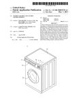
DC Motor Drive Module EDP‐AM‐MC2 EDP‐AM‐MC2 User Manual Version 1.04 Electrocomponents plc Page 1 Contents 1.0 Introduction 2.0 Command/Slave module EDP‐AM‐MC2 As A Command module EDP‐AM‐MC2 As A Slave module 3.0 Provided Software 6 Step Hall Sensored Brushless DC Motor Control Permanent Magnet Synchronous Motor ‐ Sine wave Drive PMSM with rotary encoder for position control 4.0 Solder Bridge and Link Options Vcc_CM I2C Address Selection CAN bus Voltage Reference – Vref UARTS Back EMF Detection External Motor Controller Options Rotary Encoder 5.0 Hardware Configuration PSU Arrangements Vcc_CM Options Emulator Header Serial Cables Motor Drive – Connections for 6 Step BLDC and PMSM Drive Motor Drive – Connections for PMSM with Position Control External Inputs 6.0 Software Installation 7.0 Software Configuration for 6 Step BLDC Operation Control Method Motor Type Motor Parameters Fault Protection I2C Control 8.0 Software Configuration for Sine Wave PMSM Operation Control Method Motor Type Motor Parameters Fault Protection I2C Control 9.0 Software Configuration for Sine Wave PMSM with Space Vector Modulation (SVM) 10.0 Software Configuration for PMSM Position Control Using Rotary Encoder Control Method Motor Type Electrocomponents plc Page 2 Motor Parameters Fault Protection I2C Control 10.0 Software Configuration for PMSM With Space Vector Modulation 11.0 Mixing Motor Types and Controlling With I2C Commands 12.0 Observing I2C Traffic 13.0 Adding Your Own Motor Type PMSM Sine Wave Driver with Position control 14.0 Changing The Rotary Encoder 15.0 Schematics and Layouts Revision B Revision C Electrocomponents plc Page 3 1.0 Introduction The core of the module is based around twin dsPIC33FJ128MC804 devices. These are 44 pin devices, and are capable of running at 40MIPS each. The dsPICs and provide the motor drive and control functionality to control the module. The module is 3.3V design. The capability of the module is as follows. Brushless DC Motor Control • Each dsPIC can drive a single three phase brushless DC motor. • Each drive has the capability to drive a sensored motor, with Hall sensor outputs, for basic 6 step commutation drive. • The motor drive can also drive sensorless motors, which use back EMF sensing for commutation. The op amp circuitry required to do this is provided on the board. • Each dsPIC can be operated with a rotary encoder in replace of the Hall sensors for more accurate position control/measurement. • Each output drive stage is rated for a 100W motor at 24V, giving a total of 200W per module. Brushed DC Motor Control • The Motor Drive can be reconfigured as a full bridge, brushed DC, motor speed controller. • Each dsPIC controller has one full H bridge and one half bridge available to it. • By networking the two dsPIC MCU’s together it is therefore possible to have three complete H bridge drivers. • In Brushed DC mode the Hall sensors input are not required and can be used as additional three general purpose inputs per dsPIC. Other Features • Each dsPIC motor drive MCU can sense its own motor current. Each dsPIC has an instantaneous current sense input, an additional smoothed current sense input and a logic level current FAULT comparator input. • Each dsPIC motor drive MCU can sense its own DC bus voltage for the motor, nominally 24V. • Each dsPIC motor drive MCU can read a local demand speed pot, and a local push button mounted on the board. • Each dsPIC has access to the base board back plane, where it has access to an additional 3 input/output lines. These lines are not shared with the other dsPIC on the same module, giving a total of 6 I/O lines per module. • Each dsPIC module has its own dedicated RS232 communications interface. These are available to access via a header on PCB. • Each dsPIC is connected to the Control I2C bus on the backplane and therefore has access to all the other RS‐EDP modules with an I2C interface and the two I2C devices mounted on the base board, a serial E2PROM and a serial input DIP switch latch. • Each dsPIC has the option to be connected to the external CAN bus CAN_Tx & CAN_Rx signals on the backplane via solder link options. With the addition of a communications module this will provide the physical CAN layer required for CAN bus communication. • Each dsPIC device can be connected to the serial UART0 Tx/Rx signals on the backplane via solder link options. This would allow for direct connection to the communications module RS232 interface, the RS485 Interface and the isolated RS232 interface. • Each dsPIC has its own I2C address, selectable via solder link options on the board. There are three links giving a total of 8 address combinations. • Up to four dsPIC modules can be connected to each base board. Electrocomponents plc Page 4 •
•
Each dsPIC can be debugged independently without interference from the other dsPICs / Command Modules within the board system. This allows for the debugging of one dsPIC on a module whilst the others are running complete software. The three phase bridge drive signals, and the Hall sensors input can be routed directly to the backplane without going through the dsPIC. This will allow for a Command Module such as an Infineon C167 or a ST Microelectronics STR9 to directly drive the motor via the bridge. The external controller also has access to the current sense signal and the FAULT comparator signal. This option is available via solder link options. 2.0 Command Module / Slave Module The module itself can be configured to be a Command Module in its own right. If there is no other command module in the system, then the EDP‐AM‐MC2 can be used as a Command Module. EDP‐AM‐MC2 As A Command module When the module is used as a Command Module, the solder link for the Vcc_CM on the EDP‐AM‐
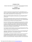
MC2 board needs to be made. This provides the back plane with the necessary voltage to instruct all the other modules that the system is a 3.3V system. i.e. The Analogue Module for example will provide signals up to 3.3V. This Vcc_CM is also used by the RESET circuitry on the base board. The RESET button will not work for example if this link is not made. As a Command Module, the dsPIC is a little restricted in I/O and hence it may have difficulty is getting the full benefit from the RS‐EDP system. It can however communicate very adequately over the I2C bus and hence it will need to set itself up as an I2C Master device in this case. EDP‐AM‐MC2 As A Slave module If the module is to be used as a Slave Module, then the solder link Vcc_CM must be open. If a 5V Command Module is used in the system, such as the Infineon C167 module, then the solder link Vcc_CM must be open on the EDP‐AM‐MC2 module, otherwise there will be a direct contention between the 3.3V and 5.0V rails. A 5V Command Module will provide a master RESET signal that rises up to Vcc_CM voltage, in this case 5.0V. The dsPIC module however, has been designed to accommodate this and will not be damaged by a 5.0V reset signal. As a Slave Device the module is controlled either via I2C packets generated from an I2C Master Device, or from push button control and the demand pot on the circuit board. 3.0 Provided Software The following evaluation software is provided with the EDP‐AM‐MC2 • 6 Step Hall Sensored Brushless DC (BLDC) Motor Control – Open Loop • Permanent Magnet Synchronous Motor (PMSM) ‐ Sine wave Drive • Permanent Magnet Synchronous Motor (PMSM) – Space Vector Modulation (SVM) • Position control using a PMSM and a rotary encoder 6 Step Hall Sensored Brushless DC Motor Control This software is the simplest form of driving a brushless DC motor. The classical mechanical commutation system of a standard brushed DC motor is replaced by an electronic equivalent based of a three phase bridge driver and electronic Hall sensors. As the motor rotates, the Hall sensors detect the position of the rotor and control the switching of the bridge accordingly. A very basic PWM control of the bridge signals provides a way of varying the voltage to the motor and hence its rotational RPM. Loading the motor, just like in the classic DC Electrocomponents plc Page 5 motor will cause the motor to draw more current and to slow down. Stalling the motor produces a stall current which is very high in relation to the normal running current. Like a standard brushed DC motor the speed is proportional to the voltage applied and the torque is proportional to the current drawn. In this implementation the motor, it can be controlled either via I2C packets or via the demand pot on the PCB and a start/stop switch. The board has been designed primarily with the I2C technique in mind. The user must decide in advance which technique he wants to use, as he will have to change a #define in the software before compilation. The push button and rotary pot is normally a good method to start with and will allow the user to quickly set the system up and check to see if the motor and Hall sensors have been wired correctly. For more accurate speed control the customer can add his own additional PID loop into the software, which will compensate for varying load demands on the motor. Permanent Magnet Synchronous Motor ‐ Sine wave Drive In this implementation, a sine wave is constructed in software and used to drive the three motor windings in a similar way to an inverter for a three phase induction motor. Each output of the PWM bridge provides a pure sine wave, which is fed directly in the winding of a motor. Each of the three phases provided is 120 phase degree shifted from the others. This way a rotating field can be generated. The speed of rotation, in this case, is controlled in software and is independent of the mechanical load. The motor does not slow down when a mechanical load is applied. The rotor of the motor, a permanent magnet, follows the rotation of the sine wave exactly. As the rotor is a permanent magnet rather than a winding there is no slippage like there is in a three phase induction motor. Consequently more accurate rotational speeds can be achieved, and a PID speed loop controller is not required. In this implementation the motor can be controlled either via incoming I2C packets or via a motor speed demand opt and a push button the PCB. The board has been designed primarily with the I2C technique in mind. The user must decide in advance which technique he wants to use, as he will have to change a #define in the software before compilation. Like the 6 step controller above the push button and rotary pot is normally a good method to start with and will allow the user to quickly set the system up and check to see if the motor and Hall sensors have been wired correctly. Theoretically the sine wave drive for the PMSM does not require Hall Effects to generate the rotating field but this application still required them as it gives us a method of checking where the rotor is prior to starting the sine wave generation. This allows the sine wave to initially synchronise itself with the rotor position. The Hall sensors also allow you to detect and measure the rotational speed of the motor. A stalled rotor for example can be detected by looking at Hall sensor transitions. Permanent Magnet Synchronous Motor – Space Vector Modulation (SVM) This implementation is very similar to the sine wave driver, but a mathematical treatment of driving six switch elements in a bridge reveals that a better more powerful drive can be achieved using a technique called Space Vector Modulation. The driving signals to each of the six bridge elements are modified to produce a stronger voltage waveform resulting in higher torque and top speed. The motor itself still sees a rotating sine wave and the three rotating voltage vectors are stronger. As in the sine wave example, the speed of rotation, in this case, is controlled in software and is independent of the mechanical load. The motor does not slow down when a mechanical load is applied. The rotor of the motor, a permanent magnet, follows the rotation of the sine wave exactly. As the rotor is a permanent magnet rather than a winding there is no slippage like there is in a three Electrocomponents plc Page 6 phase induction motor. Consequently more accurate rotational speeds can be achieved, and a PID speed loop controller is not required. As in the sine wave example, in this implementation the motor can be controlled either via incoming I2C packets or via a motor speed demand opt and a push button the PCB. The board has been designed primarily with the I2C technique in mind. The user must decide in advance which technique he wants to use, as he will have to change a #define in the software before compilation. Like the 6 step controller above the push button and rotary pot is normally a good method to start with and will allow the user to quickly set the system up and check to see if the motor and Hall sensors have been wired correctly. As in the sine wave example, the Hall effects are used to synchronise the sine wave when first starting off and also to read the actual RPM. A stalled rotor can be detected by looking at Hall sensor transitions. PMSM with rotary encoder for position control The above two examples of software are for speed control using BLDC motors. If we want position control then we need a much better resolution than a 6 step Hall sensor input. To achieve this, a rotary encoder is used. Typically these have a resolution of 500 or 1000 steps per revolution. The dsPIC hardware multiplies these counts up by a factor of two to give even better measurement of position. The only drawback with this technique is there is no way of initially sensing where the rotor is prior to running the motor. As the Hall sensor inputs have been given over to the quad encoder inputs it is not possible to know the initial position of the rotor and hence when the motor first start up after a power up sequence, the rotor may initially ‘snap’ to the sine wave when it first runs a sequence. Also, as a position controller the initial power on sequence needs to find an absolute home position. This home position locator is provided in the software. Typically a external sensor such as a limit switch is used to tell the software the motor has reached the home position. 4.0 Solder Bridge Settings and Link Options Before fitting the module PCBs into the base board, it’s worth configuring all of the solder bridge and link options. Most of the links and bridges will be set up as factory defaults for the most popular settings, but you may need to change some of these depending upon what you are trying to do. If you are using more than one BLDC module then you will certainly need to alter some of these from the factory default, in particular the I2C address selectors. The link settings are detailed as follows... Vcc_CM This link option is described in details in the section ‘Command Module/Slave Module’. If the motor drive module is to be used as a Command Module the Vcc_CM link options (R101) must be made. If there is another module in the system which is operating as a Command Module such as an Infineon C167, then the link must be left open. This link option is available only on PCB revisions C or later. For PCB revision B the Vcc_CM is a left open and there is no solder link available. The Vcc_CM pin can be tied to 3.3V if required by the use of the pins on the base board on the break out connector. Connect the 3.3v on the baseboard P603 pin 44 to the VCC_CM pin P603 pin 43. Electrocomponents plc Page 7 Fig.4.1 Vcc_CM Link option for PCB revision C or later I2C Address Selection The dsPIC on the top of the board (U201) has an I2C address selected via link options P201, P202 and P203. The default settings on the board are as follows. Top dsPIC (U201) P201 – 2/3 (logic 0) (least significant address bit) P202 – 2/3 (logic 0) P203 – 2/3 (logic 0) (most significant address bit) The dsPIC on the bottom side of the board (U202) has an I2C address selected via link options P205, P206 and P207. The default settings on the board are as follows. Bottom side dsPIC (U202) P205 – 1/2 (logic 1) (least significant address bit) P206 – 2/3 (logic 0) P207 – 2/3 (logic 0) (most significant address bit) The factory setting will likely be zero ohm links but these may be de‐soldered and replaced with solder bridges accordingly. A link between positions 2 and 3 will be read as a logic 0. A link between positions 1 and 2 will be read as a logic 1. The actual I2C Address used in the software is this link option number above added to the base address, which is defined in the ‘slave_address_defines.h’ file. The relevant #define parameter is called ‘MICROCHIP_MOTOR_DRIVER_BASE’ Note: If four modules are used in a base board design, then the two upper I2C Address’s modules will have to share External Input lines with other modules. See the section Hardware configuration – External Inputs, for more detail on this. Electrocomponents plc Page 8 Fig.4.2 Solder bridge options for the slave I2C address of the dsPIC CAN bus None of the applications contained in the code currently use the CAN bus. The board has however been designed with CAN bus in mind. The base board supports a single CAN channel and provides a path for the CAN TX and CAN RX signals to be routed through to the Communication Module which translates these signals into the physical CAN bus layer signals CANH and CANL. There is only one CAN bus Tx/RX on the back plane so only one dsPIC can be connected to the backplane at any one time. Both of the dsPICs on the board can optionally be connected to the CAN bus but not both of them. The factory default options for the CAN bus are disconnected. To connect a dsPIC to the backplane CAN Tx/Rx signals you will need to populate the missing zero ohm links. For the Top side dsPIC (U201) Populate R204, R206 with zero ohm links. Note the designation of R and not P ! For the Bottom side dsPIC (U202) Populate R214 & R215 with zero ohms links. Note the designation of R and not P ! Electrocomponents plc Page 9 Fig.4.3 Link options for the CAN bus Electrocomponents plc Page 10 Voltage Reference – Vref The voltage reference for the AD converters on the two dsPIC can be either the 3.3V rail from the motherboard or it can be from an external reference IC provided from the Analogue Module. Link option P204 can be used to select which voltage reference source is used. The factory default setting is assumed to be the 3.3V from the base board. P204 1/2 ‐ The reference voltage for the analogue is 3.3V from the base board. P204 2/3 ‐ The reference voltage for the analogue is from the AN_REF signal on the backplane, which is generated from the analogue module Fig.4.4 Analogue voltage reference selector link option UARTS The motor drive module is well equipped to support RS232 communication. The module has the facility to directly output RS232 data on to a pin header (P209) provided on the module. These signals are standard RS232 physical layer signals. Read also the section ‘Hardware Configuration’ for more details on the RS232 capability. The module also has the capability to route both of the serial outputs of the dsPICs onto the back plane as standard Tx/Rx signals at the TTL level. These are referred to as ASC0_TTL for the Topside dsPIC and ASC1_TTL for the bottom side dsPIC. This means for a system with a Communications Module, it can take this serial data in TTL format and convert it into the physical layer signals required for RS232 communication to external monitors. The communications module also has isolated RS232 and RS485 capability which may be useful in some system design. The backplane has the capability to support up to three UART channels, however we only make use of two of them here. There are three resistor options/links per dsPIC serial channel. For the Top side dsPIC (U201) To use P209 header for RS232 Communication R216 needs to be populated with a zero ohm link (factory default) R201, R203 need to be removed (factory default) Electrocomponents plc Page 11 To use the backplane ASC0 channel for RS232 communication R216 needs to be removed R201, R203 need to be populated with zero ohm links For the bottom side dsPIC(U202) To use P209 header for RS232 Communication R217 needs to be populated with a zero ohm link (factory default) R212, R213 need to be removed (factory default) To use the backplane ASC1 channel for RS232 communication R217 needs to be removed R212, R213 need to be populated with zero ohm links Be careful when using the ASC0_TTL and ASC1_TTL signals on the backplane to ensure that no other module is using the TX signals otherwise some contention will occur. Fig.4.5 UART link options top and bottom side Electrocomponents plc Page 12 Back EMF Detection Contained on the bottom side of the PCB is some analogue circuitry for signal conditioning of the signals which come off the motor windings. It is used for back EMF detection in a sensorless brushless DC motor drive application. The circuitry is included for the user, but not actually used in any of the provided software examples. The factory default setting to disable this circuitry is as follows... P502, P504, P506 – 1/2 P402, P404, P406 – 1/2 P503, P505, P507 – open P403, P405,P407 – open Fig.4.6 Back EMF circuitry link options External Motor Controller Options It is possible to drive a motor under the control of an external controller. The second dsPIC on the bottom side (U202) can be replaced by another host controller on a command module. The motor drive power stage signals and analogue current sensing and fault detection signals can be passed to the back plane for control by an external motor control processor. This means an external device such as a PIC32 can be used to drive the motor bridge and to make decisions based on the current sense feedback, the fault signals feedback and the hall/rotary encoder feedback. All this is possible with the circuitry associated with the bottom side dsPIC (U202) but not the circuitry associated with the top side dsPIC. The circuit diagram will give more clarity to this when studied. This means an external controller can only take the place of the bottom side dsPIC. To enable the dsPIC module to be controlled via an external controller, the following link options needs to be set. Hall Signals & Encoder Signals to backplane R538, R539, R540 – Populated with zero ohm link Emergency Fault/Interrupt to Backplane R542 ‐ populated with zero ohm link Current Sense Feedback R541 – populated with zero ohm link Electrocomponents plc Page 13 Motor Bridge Control Signals R334, R335, R336, R337, R338, R339 ‐ populated with zero ohm link Note: The bottom side dsPIC (U202) will have to be programmed to remain invisible in the system to prevent contention on the bridge drive pins. The factory default, is for this feature to be disabled and all of the above zero ohm resistors are not populated. Fig.4.7 External motor control link options Electrocomponents plc Page 14 Rotary Encoder When using the rotary encoder the noise reduction capacitors on the input of the Hall sensor circuit needs to be removed. This is because the data rate from the quad encoder is so fast that the edges become rounded and the quad encoder will not be able to track the rotation at high speeds. The capacitors related to the top dsPIC (U201) areC408, C409 and C410. The capacitors related to the bottom dsPIC (U202) areC508, C509 and C510. Fig.4.8 Hall sensor capacitors which need to be removed for quad encoder operation Function Vcc_CM I2C Address Selection CAN bus Voltage Reference Vref UARTs Electrocomponents plc Page 15 Parts/Links Effected R101 R101 P201 (A0) P202 (A1) P203 (A2) P205 (A0) P206 (A1) P207 (A2) R204, R206 R214, R215 P204 R216 R201, R203 R217 R212, R213 Factory Default Not present on B rev PCB C Rev – Not populated Position 2‐3 Position 2‐3 Position 2‐3 Position 1‐2 Position 2‐3 Position 2‐3 Not populated Not populated Position 1‐2 Populated Not populated Populated Not populated Back EMF Detection External Motor Control Option Rotary Encoder/Hall Effect Input P502, P504, P506 P402, P404, P406 P503, P505, P507 P403, P405,P407 R538, R539, R540 R542 R541 R334, R335, R336, R337, R338, R339 C408, C409, C410 C508, C509, C510 Position 1‐2 Position 1‐2 Open Open Not populated Not populated Not populated Not populated Not populated Hall Switches (Capacitors populated) Hall Switches (Capacitors populated) Table 4.0 Default Link Options The basic configuration of your module is now complete, to install the module, line up the connectors and press firmly along the length of the connectors. Electrocomponents plc Page 16 5.0 Hardware Configuration A single module can be used on its own without a Command Module or it can be used with other modules in more complex arrangements. PSU Arrangements The diagram in FIG.1 below shows the PSU arrangements. For best results the base board PSU will be isolated from the main motor drive power supply. This will help isolate the motor switching noise from the modules and the backplane. The grounding scheme employed on the motor drive module connects the Signal Ground and the main Power Ground together at the terminal of the power ground on the motor drive module. This is Pin8 on connector P501 on the motor drive module (this is the one with screw terminals). It is not recommended to connect the ground on the 24V Power PSU to the ground on the base board, as this will create a ground loop, which will cause a disturbance under high switching loads. This may result in unexpected behaviour of the dsPIC. The ground on the base board is also fed via an input filter choke, so the ground signal at the PSU terminal is different from the signal ground used on the modules. P501 Bottom dsPIC +DC 0V P401 Top dsPIC Electrocomponents plc Page 17 Fig.5.0 PSU connections for BLDC modules The main Power PSU should be adequately decoupled. If long cable runs are envisaged then additional smoothing/filter capacitor should be added via the screw terminals. There is a 100nF decoupling capacitor on the module between the +24V terminal and the PGnd terminal to help reduce motor noise. Vcc_CM Options The Vcc_CM (Vcc Command Module) is a voltage rail that tells the rest of the system to either use 5.0V or 3.3V as a reference. This reference is used to scale A/D converter readings from the analogue module for example and also pulls up the #RESET line to this level. Consequently the user needs to decide on a voltage level for this. This is usually decided by the Command Module. If an Infineon SAB‐C167 module is used as a Command Module, this rail is pulled up to 5.0V and hence the system operates as a 5.0V system. This dsPIC module however is 3.3V system but the RESET circuit has been designed to accommodate this. The dsPIC will not be damaged by a reset line that floats up to 5.0V. In an application where one of the dsPICs is a Command Module, then the Vcc_CM link, option/solder bridge R101, needs to be made (PCB Rev C or later). Ensure this link is soldered when the dsPIC is the Command Module. It may well be that in an application where one of the dsPIC’s on the module is configured as a Command Module and I2C Master and the other as an I2C Slave, then the Vcc_CM link should be made as if the whole module was a Command Module, and the R101 link should be closed. If the Infineon CM module has Vcc_CM configured as 5.0V and the dsPIC module has Vcc_CM solder link made (configured as 3.3V), then there will be a direct short between the 3.3V and 5.0V power supply rails. This should be avoided for obvious reasons. For PCB revision B the Vcc_CM is a left open and there is no solder link available. The Vcc_CM pin can be tied to 3.3V if required by the use of the pins on the base board on the break out connector. The factory default setting is for the Vcc_CM link to be left open. Emulator Header There are two positions for the emulator header (P208), one for each of the two dsPICs. The one closest to the edge of the PCB controls the dsPIC (U201) that is visible on the top of the PCB , whilst the second emulator header controls the other one (U202) on the reverse side of the PCB. Whilst debugging is useful to debug code on the device on the top of the board, as the MCU pins are accessible for probing. Having two positions for the emulator allows the emulator/programmer to debug and flash one of the dsPIC MCU’s whilst the other one is running normal application code. Reset signals generated by the emulator whilst debugging/programming are not propagated on to the #RESET line on the backplane so all other dsPIC’s and other modules are not affected by the actions of the debugger/programmer. Note: When the REAL‐ICE/ICD2 is running a debug session it is important on the early revisions of the PCB (Rev.B) not to press the external reset line for any length of time as the RESET signal will try and pull down the emulator control line. The baseboard #RESET line is, however, correctly asserted and all other modules connected to the #RESET line will see the #RESET line function correctly. Electrocomponents plc Page 18 On later versions on the PCB (Rev.C) this problem is fixed, and there are no restrictions on the #RESET signal. For customer with the older version of the PCB who wish to fully use the #RESET signal without restriction during the debug phase then simply remove the diode (D101/D102) and then replace when the software is completed. Pin.1 Fig.5.1 Debugger and serial cable connections Serial Cables Each dsPIC module is equipped with two full RS232 transceivers. This means each dsPIC has access to physical layer Tx and Rx signals and can communicate freely with a host PC terminal. These ports are enabled as the default setting for the link options also. These are very useful for debugging of the application and report lots of details during the running of the application. If something does not work correctly then plug in a terminal and more often than not the problems can be identified via the help menu options or the text outputted from the dsPICs. Provided with the kit is a header to allow each board to talk to two separate RS232 terminals. Plug in the twin serial cable provided with the board. The PCB header end of the cable assembly has pin 1 marked with a small arrow. Pin 1 on the corresponding header on the PCB (P209) is also marked. The serial configuration at the time of writing this support documents is as follows. Check the C source code to see if this has changed since this document was written. Baud rate: 115,200 baud Data bits: 8 Stop bits: 1 Parity: None Flow control: None As you will no doubt appreciate you may be running out of serial ports on your PC. There are plenty of USB‐RS232 converters on the market, which should allow you to expand the number of serial channels. I have found using Windows Hyper Terminal with Microsoft uncertified converters yields PC system crashes. For this reason you might want to try the DSA’s MTTY Terminal Program. This has proved a lot more robust than Hyper Terminal when using USB‐RS232 converters. The most rugged of systems I have tried uses a PMCIA adapter card to RS232 converter. The options for DSA’s MTTY program in addition to the above settings are: Local Echo – unticked Display Errors – ticked Electrocomponents plc Page 19 Add Cr or Lf – unticked Autowrap – ticked Use Parser – unticked Fig.09 shows the cable access points on the PCB.
Electrocomponents plc Page 20 Motor Drive – Connections for 6 Step BLDC and PMSM Drive The wiring diagram to connect two BLDC motors to the board is shown in Fig5.2. Note the Hall sensors on the motors required +5V and Gnd to operate correctly. On the connector there is only one set of 5V/Gnd connections, so for a twin motor application, these terminals will have to be shared, to power the Hall sensors on both of the motors. P501 P401 Fig.5.2 Motor connections for 6 Step BLDC and PMSM Drive Electrocomponents plc Page 21 Motor Drive – Connections for PMSM with Position Control The wiring diagram for the PMSM with Position Control using a 5V TTL rotary encoder is shown in Fig.5.3 The wiring diagram for position control is slightly different from the one above, as there are no Hall sensors to connect. The rotary encoder does however use the same connections. Note: The noise reduction capacitor on the Hall sensor input need to be removed for rotary encoder operation. See the section on link options. Fig.5.3 Motor connections for PMSM with position control using rotary encoder For applications that use a 24V rotary encoder the encoder can be powered off the +24V supply, but the sensors output will have to be converted to TTL levels before entering the motor drive module. The encoder input will be able to tolerate a reasonable degree of noise as there is a digital filter set up on its inputs. However, too much noise will result in poor operation of the drive. Make sure the PSU supply is adequately decoupled and the outputs from the quad encoder are reasonably clean and free from noise. Some rotary encoders have 4‐20mA loop outputs. To use these types you will need to build an interface board prior to entering the module, designed to handle such signals. Electrocomponents plc Page 22 External Inputs For the 6 Step BLDC and the PMSM Drive software there are 6 external inputs available which can be directly read by the dsPIC MCU. These are available on the external edge connectors P601 and P602. The inputs are as follows... External Input 0 dsPIC A (U201) (Top side dsPIC) External Input 0 is mapped to EVG12_GPIO60 dsPIC B (U202) (Bottom side dsPIC) External Input 0 is mapped to EVG15_GPIO63 External Input 1 dsPIC A (U201) (Top side dsPIC) External Input 1 is mapped to EVG13_GPIO61 dsPIC B (U202) (Bottom side dsPIC) External Input 1 is mapped to EVG16_GPIO64 External Input 2 dsPIC A (U201) (Top side dsPIC) External Input 2 is mapped to EVG14_GPIO62 dsPIC B (U202) (Bottom side dsPIC) External Input 2 is mapped to EVG17_GPIO65 The dsPICs are free to use these I/O pins for limit switches etc. The pins do not have any input protection on them, and need to be protected if the cable runs are susceptible to noise. A digital I/O module could also be used to expand the available I/O pins using the I2C bus to communicate. For the PMSM with Position Control Software these sensor inputs are generally used for a home sensor locating switch. The position controller will require a ‘home’ sensor to reference itself against. This is normally a trip or level switch sensor, included within the travel path of the motor actuator. This will signal when the motor has reached its start of travel or home reference point. There are 6 external input signals to the motor drive module. These have been allocated for this purpose. Therefore, we can have up to 3 modules (a total of 6 dsPICs), each with its own unique home sensor. The allocation for these is based on the I2C address of the motor drive device. As we may have up to 3 modules (6 x dsPICs) the software has been written to accommodate this. As all three boards cannot use a home sensor on GPIO60 for example, all three boards must access a different external input. For this reason the software makes use of the I2C address, set with the DIP switch/Solder Bridge settings on the motor drive board. The purpose of this is so all 6 dsPICs can be flashed with the same version of the software. The relationship between the DIP switch/Solder Bridge and the input channel read is detailed below. For DIP switch == 0 and DIP switch == 1 (I2C address 64 & 65), we read the External Input 0 For DIP switch == 2 and DIP switch == 3 (I2C address 66 & 67), we read the External Input 1 For DIP switch == 4 and DIP switch == 5 (I2C address 68 & 69), we read the External Input 2 If you are unsure as to what the solder bridge settings are on your board, one of the menu options in the software will read the Dip Switch/Solder Bridge settings for you. From this you can determine which external I/O pin you need to connect the External Input to. Note: For applications that use four boards, we do not have enough I/O for each dsPIC to have its own unique dedicated input. For this reason the top two I2C address locations cannot be used with the position control software, without modification to the provided software. The original design of the board had these solder links as DIP switch setting, but due to the tight constraints the DIP switch has been removed and replaced with solder bridge optons. Electrocomponents plc Page 23 Fig.5.4 Wiring diagram for home sensors Electrocomponents plc Page 24 6.0 Software Installation The software has been written with the Microchip C Compiler C30 and developed using MPLAB Version 8.14 To make use of the software and to configure the module for use, you will need to install the software. Both the MPLAB IDE and the C Compiler is available from Microchip website. Download these and install as per the manufacturer’s instructions. 7.0 Software Configuration for 6 Step BLDC Operation For the purposes of setting the system up make sure you have a current limited power supply for the main Motor PSU. This will prevent damage to the board and the motor. Connect an RS232 terminal emulator to the device using the provided cable. Make sure the orientation of this cable is correct otherwise the serial output will not work. Connect the header to P209 on the PCB ensuring correct orientation, pin 1 is nearest to the corner of the PCB. Open up the MPLAB project workspace called ‘RS_EDP_AM_MC2’ which should be located in the ‘RS_BLDC_Module\software’ directory. Compile this project and see if the compilation goes to completion without problem. You may have to tinker with the project slightly to ensure all the paths are correct and all of the relevant header files can be found. The projects make use of the Microchip libraries to configure some of the device peripherals. Connect your Real ICE/ ICD2 debug tool to the device using the header cable provided. Use the tools as a ‘Programmer’ initially rather than a ‘Debugger’ and set the project option to ‘Release’. Once a successful application has been compiled you can download the code in to the flash memory of the device. Program the code into the device. Once the code has been flashed the device should start to run and message strings will start to be displayed on the terminal screen. If all of this works correctly then you are ready to start to tune the motor drive board to the BLDC motor. Go back to the MPLAB project and locate the ‘defines.h’ header file. Open this header file and examine the #defines and their description. Some of the major ones are described below. Control Method The header file allows you to specify how you want to control the motor, either through I2C packets from an I2C Master or from the push button on the PCB and the demand speed pot on the PCB. To enable us to get started it is best to select the control by push button option initially. This is the most simplest of the control setting, and it will allow for basic tuning of the motor and the safety trip levels. The header file has the following code... /* Select your control option below */ #define CONTROL_BY_I2C 0u #define CONTROL_BY_PUSH_BUTTON 1u #define CONTROL_METHOD CONTROL_BY_PUSH_BUTTON Electrocomponents plc Page 25 As you can see there are two #defines followed by a third one which allows us to select either of the other two defines. For the control by push button the third line should read... #define CONTROL_METHOD CONTROL_BY_PUSH_BUTTON And for control by I2C packets from a master this third line should be change to #define CONTROL_METHOD CONTROL_BY_I2C So to start with, this line should read #define CONTROL_METHOD CONTROL_BY_PUSH_BUTTON Motor Type The next set of #defines we need to alter are the ones which are specific to the motors. The software has been written to accommodate two BLDC motors, the Hurst Dynamo and the Maxon EC type. The Maxon EC type is a popular selling motor available from RS Components and the Hurst one is available to order via Microchips web site. /* Define The Motor Type */ #define HURST_DYNAMO_DMB0224C10002 1u /* Hurst Motor */ #define MAXON_EC_118898 2u /* Maxon motor */ #define MOTOR_TYPE MAXON_EC_118898 If you are going to use one of the two motors above then change the third #define to select one of the predefined motor types. i.e. #define MOTOR_TYPE MAXON_EC_118898 or #define MOTOR_TYPE HURST_DYNAMO_DMB0224C10002 Motor Parameters The motor you have selected above has some additional defines related to it. These are detailed below /* This group of Defines relates to the motor types and hall effect combination */ #if (MOTOR_TYPE == HURST_DYNAMO_DMB0224C10002) #define POLES 10u /* number of poles (2 x pole pairs) in the motor */ #define MAX_MOTOR_RPM 4000u /* Approximate Maximum RPM spindle speed for the motor, when running at no load in the application */ /* This parameter is not that relevant when using the 6 step control method */ /* This parameter is however significant when using the PMSM sine driver technique */ #define MAX_INSTANT_MOTOR_CURRENT 800u /* Maximum allowable current in mA */ #define MAX_AVERAGED_MOTOR_CURRENT 800u /* Maximum allowable filtered current in mA */ #define IMOTOR_AV_FAULT_DETECTION ENABLED #define IMOTOR_AV_COUNTER_THRESHOLD 300u Electrocomponents plc Page 26 /* Alter this value to alter the trip sensitivity to this parameter */ #define IMOTOR_FAULT_DETECTION ENABLED #define IMOTOR_COUNTER_THRESHOLD 300u /* Alter this value to alter the trip sensitivity to this parameter */ #define EXT_COMPARATOR_FAULT_DETECTION ENABLED #define EXT_FAULT_COUNTER_THRESHOLD 200u /* Alter this value to alter the trip sensitivity to this parameter */ The main parameters for the 6 step configuration are the number of poles (2 x pole pairs) and the type of fault detection and trip you wish to implement. The maximum RPM figure is not actually used in the 6 step controller. Initially we will set the both of the current trips and the external current comparator to off. To do this alter the #define lines to #define IMOTOR_AV_FAULT_DETECTION DISABLED #define IMOTOR_FAULT_DETECTION DISABLED #define EXT_COMPARATOR_FAULT_DETECTION DISABLED These parameters can be one of two values, either ENABLED or DISABLED. Once this is done we can recompile the software and download the flash into the board. Flash the board with a programmer and set the code running. Check the RS232 monitor channel to see if there is output. The software has been written so that a countdown sequence is initiated. If a keyboard press is registered during the countdown sequence the test menus are displayed. This will allow you to fully exercise the hardware and ensure the motor and hall sensors are correctly configured before actually running the motor in a real application. Failure to press a key a key during this countdown sequence will result in the software executing in the normal run mode motor drive software. Start by sequencing through the menu options, ‘1’ to ‘b’ and exercise the hardware you have. Note: All of the fault detection algorithms that are designed to protect the motor and circuitry become disabled during this menu phase so make sure you have a current limited power supply. These menus are a good way of checking the hardware is working correctly. Electrocomponents plc Page 27 Fig.7.0 Screen shot from main test menu After running through options ‘1’ to ‘b’ exit the menu program with option ‘q’. We are now in the main loop speed controller for the BLDC motor. Centre the demand speed pot on the board and then press the START button on the PCB. The motor will rotate at a speed determined by the pot setting. Move the pot and watch the motor. Load the motor and notice how the speed of the motor varies with this loading. Rotating the pot full clockwise will cause the motor to achieve maximum speed in the one direction and then turning the pot anti clockwise fully will cause the motor to turn on the opposite direction at full speed. Be careful not to twist the pot too fast as the rotor may not be able to accelerate too quickly and may stall. If the motor cannot reach maximum speed as set in the #defines then this may be due to the mechanical loading or due to the fact that the Vbus motor supply voltage is too low. Once you are happy the motor can be rotated correctly and the wiring to the phases and the Hall sensors is correct we can move on to including the fault protection circuitry in to the application. Fault Protection Open up the defines.h file again and go back to the motor parameters again, and alter the parameters for the motor type you are using. Below it is shown for the Hurst motor. Electrocomponents plc Page 28 #if (MOTOR_TYPE == HURST_DYNAMO_DMB0224C10002) #define POLES 10u /* number of poles (2 x pole pairs) in the motor */ #define MAX_MOTOR_RPM 4000u #define MAX_INSTANT_MOTOR_CURRENT 800u /* Maximum allowable current in mA */ #define MAX_AVERAGED_MOTOR_CURRENT 800u /* Maximum allowable filtered current in mA */ #define IMOTOR_AV_FAULT_DETECTION ENABLED #define IMOTOR_AV_COUNTER_THRESHOLD 300u /* Alter this value to alter the trip sensitivity to this parameter */ #define IMOTOR_FAULT_DETECTION DISABLED #define IMOTOR_COUNTER_THRESHOLD 300u /* Alter this value to alter the trip sensitivity to this parameter */ #define EXT_COMPARATOR_FAULT_DETECTION DISABLED #define EXT_FAULT_COUNTER_THRESHOLD 200u /* Alter this value to alter the trip sensitivity to this parameter */ Start with the ‘Average Current’ setting and decide what level of average current in mA will be denoted as a fault current. The Hurst motor has a high impedance winding so the fault current is normally less than 1000mA. The fault current can be chosen with the following in mind... • How hard will my motor need to accelerate? • How much torque is required by my application? • If there is a short in the wiring or winding, how much current will the drive see? • If the rotor stalls, what is the likely fault current it will see? Once you have some appreciation of this figure you can enter it as mA as shown below. #define MAX_AVERAGED_MOTOR_CURRENT 800u The Average Current and Instantaneous Current are obtained by two different methods. The Average Current is derived from a signal that has lots of capacitor smoothing on it. Consequently this gives some indication of the average running current for the motor, but is rather slow to react. The Instantaneous Current signal is also measured by the unit but this signal does not have any capacitor smoothing on it. Consequently its a quick acting signal but prone to noise. The Instanaeous Current level can also be set with a #define #define MAX_INSTANT_MOTOR_CURRENT 800u This figure can be different from the Average Current figure. We will concentrate on the Average Current figure initially and then enable the Instantaneous Current option later. OK, the Average Current trip level has been set, but the problem now arises in that during acceleration the motor will demand more current. We will not want the motor to constantly trip out due to noise spikes or when it is accelerates under load for example. To help with this, a basic trip Electrocomponents plc Page 29 counter has been implemented, which checks the current every 1ms or so. If a fault condition is present it adds one to the trip counter and if it is not present 1 is subtracted from it. Once the trip counter hits a certain threshold, the fault is deemed to be present and the motor is stopped under an emergency stop manoeuvre. This trip level and whether it is ENABLED or not, is determined with the #defines... #define IMOTOR_AV_FAULT_DETECTION ENABLED #define IMOTOR_AV_COUNTER_THRESHOLD 300u As you can see here, the trip will activate after approximately 300ms or so of a fault condition being present. To get some indication of the current being drawn by your application have a look in the test menu and run the ‘Read Motor Current & FAULT Signal’ test. The figure, in mA, is indicated. Load the motor as it would be under normally running conditions and then try stalling the motor. This will give you some indication as to what figures you should be using for the motor trip current. Use a current limited PSU for this whilst doing these tests. Set the #defines to a suitable level for your application and then recompile the code and download in to the dsPIC. Rerun the software, this time in the normal run mode, and see if the Average Current Trip function is working. Once you are happy with this, you can move on to the Instant Motor Current #define MAX_INSTANT_MOTOR_CURRENT 800u And it’s associated trip level. #define IMOTOR_FAULT_DETECTION ENABLED #define IMOTOR_COUNTER_THRESHOLD 300u This is a slightly faster acting signal and provides a quick way of detecting a stalled rotor at high speeds. The last protection feature encompassed in the software relates to the external comparator that is provided in hardware on the board. This is basically a trip level that is set on a potentiometer on the board. The comparator is fed by the averaged filtered signal. #define EXT_COMPARATOR_FAULT_DETECTION ENABLED #define EXT_FAULT_COUNTER_THRESHOLD 200u This feature is effectively duplicated by the software algorithms above but has been included as another way of providing circuit protection. The FAULT signal is read by software but the condition could be triggered by an Interrupt for a faster way of stopping the motor. I2C Control Once you have the motor spinning under the control of the potentiometer and the stop button, we can evolve the product so it can be controlled via I2C commands. As there are two dsPICs on the board we can set one up to be an I2C Master and the other one to be set up as I2C Slave. Note there can be only one I2C Master in the system as the software has not been written to cope with multi master I2C operation. Go back to the ‘defines.h’ file and modify the control method to... #define CONTROL_BY_I2C 0u Electrocomponents plc Page 30 #define CONTROL_BY_PUSH_BUTTON 1u #define CONTROL_METHOD CONTROL_BY_I2C Recompile the code and flash both of the dsPICs with the same software. Make sure the MPLAB is configured as a ‘Programmer’ and the build type is set for ‘RELEASE’, before recompiling. Once this is done, press the RESET button on the base board. Observe both of the two serial outputs from the devices. The serial output from the device with the blushless DC motor connected will be used as the I2C Slave and the other one will use as the I2C Master. For the I2C master device, hit the return key before the countdown sequence has expired. From the menu option that is provided select some of the I2C commands. Fig.7.1 Terminal screen shot of menu options As menu options ‘1’ through to ‘b’ have already been selected and run, we do not need to repeat them again here. Select menu options ‘c’ and check to see what other I2C devices the I2C Master can see in the system. Electrocomponents plc Page 31 Fig.7.2 I2C master mode menu output The I2C Master will poll the I2C bus and identify which devices respond with an acknowledge signal. The above diagram shows four dsPIC I2C Slave devices at I2C address 65, 66, 67,and 69. The I2C Master does not respond to its own I2C address ping. Consequently in the above system there are four dsPICs configured as slaves and one configured as a master. If a dsPIC is configured as a master, it is not possible with the current software for it to be used as a motor driver as well. The other I2C address (081) identified in the above diagram, is the serial E2PROM present on the base board. There may well be other devices identified including the serial input latch on the base board and the devices on other modules. Run test option ‘f’ Test The 24LC32 Serial EEPROM On The Base Board’ to ensure the I2C is functioning correctly. If all is working correctly proceed to menu option ‘h’ – Send the other dsPICs I2C Control Commands’. Fig.7.3 Selecting the I2C we want to control Electrocomponents plc Page 32 As there may be up to 7 motor drives controllable via I2C packets from this one I2C Master in the system, we need to tell the software which I2C device address we want to communicate with. Select the address of the I2C Motor Drive Slave you want to control using the ‘+’ and ‘‐‘ keys. Once you have reached the I2C address, hit the return key and a complete new set of menu options appears. Fig.7.4 I2C command menu Built in to the software is a set of I2C Command, which will allow the I2C Master to communicate with the I2C Slave devices. The command set is detailed in a text documents contained in the header files directory called ‘Slave I2C Command Protocol.txt’ This describes the I2C packet contents, which has been implemented in software. This command protocol is very similar for the motor drive algorithms from the 6 step controller through to the position controller. There are extra commands added in the other drives as the drives are more complicated and they require a more comprehensive command set. From this menu, sequence through the options shown and become familiar with the features of the provided software. Ping the address initially to see if you have contact with the slave. If the slave address you want to communicate to is going through its countdown sequence just after power up then the Slave is not yet configured and will not respond. Once the sequence has finished the slave is available for control. This can be easily shown by selecting the I2C menu option ‘1 – RESET the Slave Address MCU’ followed immediately by option ‘0 – Ping the Address’. To get the motor to move in a 6 step drive, then the following sequence needs to be sent... Menu option ‘4 – Set The New Direction As Forward’ Menu option ‘6 – Set the Ramp Up Speed’ Menu option ‘7’ – Set the Ramp Down Speed’ Menu option ‘8 – Set The Motor Demand Speed Forward’ Menu option ‘a – Set The Motor Turning’ For the ‘Ramp Up’ speed we can chose typical values of 1 – 20 depending on whether we want a slow ramp up speed (small number) or a faster ramp up (larger number). Electrocomponents plc Page 33 The user has to appreciate what load is on the motor unit to prevent the motor from stalling during ramp up and ramp down. Too high a value will cause excessive current to be drawn and the fault protection circuitry may activate also. The user therefore has to set the current trips and the acceleration and deceleration ramps accordingly, based on his understanding of the load types being driven. In the 6 step controller the user can alter the speed of the drive on the fly without stopping the motor. To do this select menu option ‘8’ and select a new speed using the ‘+’ and ‘‐‘ keys. The slave motor will respond to the new demand speed. To drive the motor in reverse or counter clockwise the user first has to stop the motor. Select... Menu option ‘3 – Normal Stop’. The motor will then decelerate according to the ramp down profile selected. Menu option ‘2 – Emergency Stop’ will cut power immediately to the drive and the motor will free wheel to its stationary position. The ramp down profile is not respected during this emergency stop phase. To turn the motor in the opposite direction we have to set up the new direction and the reverse demand speed. Menu option ‘5 – Set The New Direction As Reverse’ Menu option ‘9 – Set The New Demand Speed Backwards/Counter Clockwise’ Menu option ‘a – Set The Motor Turning’ As the ramp up and ramp down rates have already been set, these do not have to be retransmitted. The motor will accelerate to the new demand speed where it will remain until another command is sent to it. The slave module keeps the Reverse and Forward speeds separately, so changing direction does not always have to be followed by a new Demand Speed. The motor must be stopped before changing direction. The motor cannot change direction when it’s accelerating, decelerating or in normal running mode. The only way to change direction is when the motor is in the stopped mode. The master can poll the slave to determine what state it is in. The current states are detailed in the ‘defines.h’ file and they are... /* Machine States for I2C Control */ #define STOPPED 0u #define STOPPING 1u #define NEW_MOTOR_DEMAND_FORWARD 2u #define NEW_MOTOR_DEMAND_REVERSE 3u #define NORMAL_RUNNING 4u The software for sine wave drive and for position control has a different selection of states as the control strategy is different. You can poll the slave and determine what state it is. You can see this status information with menu option ‘g – Read The Motor Status Flags’. Start the motor running again and whilst it’s running select this menu option. Electrocomponents plc Page 34 Fig.7.5 Reading the status information from the slave Included in the status information is the RUN/STOP flag of the motor, the direction of the motor rotation, and fault information relating to RPM, Instantaneous Current, Average Current and External Current comparator. The current state (state machine) of the motor is also displayed which for the one of the five states detailed above. The sine drivers and position controller software make use of the RPM fault flag and also have an extended state machine table. The menu options also allow you to examine motor current and bus voltages etc. Cycles through each of the menu options in turn, and watch the parameters displayed in real time on the terminal. Where a parameter such as motor current is displayed, there are two figures displayed. The first is normally the instantaneous figure and the second is normally a software averaged figure. After completing all the menu options, run the last one, option ‘z – Exercise a Sequence of Tests’. This last menu option puts together all of the above options and cycles through them one by one. This last one provides a quick test of the motor. If the motor trip currents need to be altered then alter the #defines in the ‘defines.h’ header file and recompile. Then flash the new code into the SLAVE device you want to change. You do not need to re‐flash the master device in this case. Re‐flashing the MCU will cause that MCU to RESET but all other devices on the bus are unaffected. This way each motor can be debugged and its software changed independently whilst the rest of the system can be running and operating motors. 8.0 Software Configuration for Sine Wave PMSM Operation The procedure for setting up a permanent magnet synchronous motor (PMSM) is similar to the one for the Six Step Controller. The software is contained in a different directory, called RS_BLDC_PMSM. The MPLAB project workspace is called ‘RS_EDP_Microchip_PMSM’ Open this project workspace and examine the source files. The wiring for the 6 step controller is exactly the same as for the sine wave drive PMSM. The same Hall sensors are used and the same bridge driver also. For the purposes of setting the system up make sure you have a current limited power supply for the main Motor PSU. This will prevent damage to the board and the motor. Connect an RS232 terminal emulator to the device using the provided cable. Make sure the orientation of this cable is correct otherwise the serial output will not work. Connect the header to P209 on the PCB ensuring correct orientation. Compile this project and see if the compilation goes to completion without problem. As with the six step controller you may have to tinker with the project slightly to ensure all the paths are correct and Electrocomponents plc Page 35 all of the relevant header files can be found. The projects make use of the Microchip libraries to configure some of the device peripherals. Connect your debug tool to the device using the header cable provided. Use the tools as a ‘Programmer’ initially rather than a ‘Debugger’ and set the project option to ‘Release’. Once a successful application has been compiled you can download the code in to the flash memory of the device. Program the code into the device. Once the code has been flashed the device should start to run and message strings will start to be displayed on the terminal screen. If all of this works correctly then you are ready to start to tune the motor drive board to the BLDC PMSM motor. Go back to the MPLAB project and locate the ‘defines.h’ header file. Open this header file and examine the #defines and their description. Some of the major ones are described below. Control Method The header file allows you to specify how you want to control the motor, either through I2C packets from an I2C Master or from the push button on the PCB and the demand speed pot on the PCB. A detailed description of this is contained in the above section for the 6 step controller. To enable us to get started it is best to select the control by push button option initially. The header file has the following code... /* Select your control option below */ #define CONTROL_BY_I2C 0u #define CONTROL_BY_PUSH_BUTTON 1u #define CONTROL_METHOD CONTROL_BY_PUSH_BUTTON Motor Type Select the motor you wish to use. The one below is configured for the Hurst motor. /* Define The Motor Type */ #define HURST_DYNAMO_DMB0224C10002 1u /* Hurst Motor */ #define MAXON_EC_118898 2u /* Maxon motor */ #define MOTOR_TYPE HURST_DYNAMO_DMB0224C10002 Motor Parameters The motor parameter selection has some additional ’#defines’ related to it. These are nominally the RPM fault detection parameters. All of the defines are detailed below /* This group of Defines relates to the motor types and hall effect combination */ #if (MOTOR_TYPE == HURST_DYNAMO_DMB0224C10002) #define POLES 10u #define MAX_MOTOR_RPM 2500u /* Note you will need to change the Amplitude Reduction Table in the ‘sine_driver.c’ file to accommodate the change in Maximum RPM */ #define MAX_INSTANT_MOTOR_CURRENT 800u #define MAX_AVERAGED_MOTOR_CURRENT 800u #define MIN_MEASURABLE_RPM_SPEED 60u Electrocomponents plc Page 36 #define RPM_FAULT_DETECTION DISABLED #define RPM_COUNTER_THRESHOLD 1000u #define IMOTOR_AV_FAULT_DETECTION DISABLED #define IMOTOR_AV_COUNTER_THRESHOLD 300u #define IMOTOR_FAULT_DETECTION DISABLED #define IMOTOR_COUNTER_THRESHOLD 300u #define EXT_COMPARATOR_FAULT_DETECTION DISABLED #define EXT_FAULT_COUNTER_THRESHOLD 200u Note: Also the maximum RPM figure is significant in the sine driver PMSM software. The reason for this is explained as follows... When the motor is running at maximum RPM, 2500 RPM in this case we would expect the motor to be receiving the full amplitude sign wave. This will effectively deliver maximum voltage and hence maximum current to the motor. The motor as its spinning rather quickly it will deliver a back EMF proportional to its rotational speed and hence the current flowing through the winding will be limited. The torque available is proportional to the current, and the motor should be selected to be able to provide enough torque for the application. At low RPM the motor is not able to provide a strong back EMF and so the current in the winding would increase massively unless the voltage to the motor is reduced accordingly. Consequently a voltage reduction is necessary to prevent the motor from drawing excessive current at lower speeds. This trade off is achieved by a Voltage/Frequency voltage reduction table. This technique is common employed in three phase inverters or three phase AC motor drive applications. The ratio of V/f is usually a constant but some allowances need to be made for the fact that the motor is a real item and not a theoretical model. Consequently any change in the Maximum RPM figure will ultimately reflect in a different voltage reduction pattern or table. The voltage reduction table is contained in the file ‘sine_driver.c’ A table is used rather than mathematics as it provides a quicker way of actually doing the maths. Have a look at the two tables and you will note that a table entry of ‘255’ means full power sine wave and a vale of ‘128’ for example is half of full scale voltage. The relationship of the Voltage and Frequency is usually linear from full speed down to zero, with some provision for maintaining a voltage at a minimum low level for really slow speeds. A details study of the V/F relationship for PMSM with complete mathematical treatment can be found on the web. Marek Stulraijter, Valeria Hrabovcova and Marek Franko have published a paper in the Journal of Electrical Engineering Vol.58 No.2, 2007 entitled ‘Permanent Magnets Synchronous Motor Control Theory’. The sine wave V/F reduction table is selected automatically for the two motors profiled in here but the user will have to create a new table for any new motors he uses. The big advantage of this type of motor drive is that the rotor rotates in perfect synch with the applied sine wave. Provided the torque of the load does not cause the motor to stall, the motor will effectively rotate at the frequency of the driven sine wave. The other big advantage of this that the Electrocomponents plc Page 37 applied torque is much smoother and so the motors run more silently and the consequent torque ripple is much less. The disadvantage of this type of drive over the six step, is the switching losses are much higher as a sine wave has to be reconstructed from a DC levels. It was also found that the maximum RPM figure of the motors is much less when driven with a sine wave over the 6 step approach. To set the motor up, follow the same technique as for the 6 step by removing all of the fault detection and trip elements. We would also have to switch off the RPM fault detection, which is a new feature in the sine drive example. Initially we will set the both of the current trips and the external current comparator to off. To do this alter the #define lines to #define IMOTOR_AV_FAULT_DETECTION DISABLED #define IMOTOR_FAULT_DETECTION DISABLED #define EXT_COMPARATOR_FAULT_DETECTION DISABLED #define RPM_FAULT_DETECTION DISABLED These parameters can be one of two values either ENABLED or DISABLED. As we are driving the rotor with a predefined sine wave of a given frequency we should be able to determine more easily whether we have a stalled rotor, as we can measure quite easily the RPM of the motor from the Hall sensors inputs. By measuring the time between Hall transitions and knowing the number of poles in the motor we can determine the actually rotating RPM. This can be compared with the driven frequency and we can therefore determine whether we have a stalled rotor or not. This technique does fall down at low RPM however as the timers used to measure the time between Hall transitions will roll over. For this reason we have a minimum RPM speed at which the RPM fault detection is deactivated. The user will need to specify the point at which he would like this to operate. This is the purpose of the #define MIN_MEASURABLE_RPM_SPEED 60u Use a current limited power supply initially when first commissioning and setting up a motor. Once this is done we can recompile the software and download the flash into the board. Flash the board with a programmer and set the code running. Check the RS232 monitor channel to see if there is output. The software has been written so that a countdown sequence is initiated. If a keyboard press is registered during the countdown sequence the test menus are displayed. This will allow you to fully exercise the hardware and ensure the motor and hall sensors are correctly configured before actually running the motor in a real application. Failure to press a key a key during this countdown sequence will result in the software executing in the normal run mode motor drive software. Start by activating the menu options and then exercise the hardware you have by sequencing through all of the options, one at a time. Note: All of the fault detection algorithms that are designed to protect the motor and circuitry become disabled during this menu phase so make sure you have a current limited power supply. These menus are a good way of checking the hardware is working correctly. The main menu for the PMSM looks identical to the 6 Step menus. Electrocomponents plc Page 38 Exercise the menu options ‘1’ through to ‘b’ and when you are happy the hardware is functioning correctly exit the menus, ‘q’ and the main control loop will start. Centre the demand speed pot on the board and then press the START button on the PCB. The motor will rotate at a speed determined by the pot setting. Load the motor and notice how the speed of the motor does not vary. This is because the motor is rotating in synch with the sine wave driving it. The current to the motor does however change depending upon its loading. Too much load and the motor will stall. Rotating the pot full clockwise will cause the motor to achieve maximum speed in the one direction and then turning the pot anti clockwise fully will cause the motor to turn on the opposite direction at full speed. This max speed is defined in the ‘#defines.h’ file. Be careful not to twist the pot too fast as the rotor may not be able to keep up with the sudden changes in demand and it may stall. If the motor cannot reach maximum speed as set in the #defines without stalling then this may be due to the V/F table settings or due to the fact that the motor is unable to deliver the required torque at this high speed setting. If this is the case then either reduce the maximum RPM figure or alter the V/F table or try a different motor control algorithm. Fault Protection After doing these brief tests, go back to MPLAB and put the safety trips in place. Start with the #define IMOTOR_AV_FAULT_DETECTION ENABLED And work thorough to include them all including the new RPM fault trip which was not present in the Six Step Controller. See the section on 6 Step Controller for more detail on the following three trips... #define IMOTOR_AV_FAULT_DETECTION DISABLED #define IMOTOR_FAULT_DETECTION DISABLED #define EXT_COMPARATOR_FAULT_DETECTION DISABLED The following trip requires some additional explanation... #define RPM_FAULT_DETECTION ENABLED The RPM detection algorithm is useful and relatively easy to implement. The software will look at the target RPM speed and the actual RPM speed and make a comparison. The user has two values for RPM. One is the ‘instantaneous RPM’ and the other in the ‘average RPM’ figure. The fault detection algorithm is implemented in ‘fault_detection.c’ and makes use of the ‘instantaneous RPM’ value, as this is more up to date. For the RPM fault detection algorithm to work, the target speed must be above the minimum speed set in the #defines.h file. The RPM is said to be at fault when it lies outside two boundaries. The two boundaries are 150% and 50% of the desired target speed. These are set up in the ‘fault_detection.c’ file. The instantaneous RPM will lag slightly the desired RPM during acceleration and deceleration. The user can hand tweak this software to get safety/performance trade off. Each time the fault detection algorithm is called, and it is deemed to be out of range, a fault counter is incremented just like on the other trips. If it is in range the fault counter is decremented. When the fault counter reaches a threshold count the fault is deemed to be present and the fault flag is set, bringing any motor control activity to a stop. Electrocomponents plc Page 39 I2C Control Once you have the motor spinning under the control of the potentiometer and the stop button, we can evolve the product so it can be controlled via I2C commands. Like on the 6 step controller we can set one dsPIC up to be an I2C Master and the other one to be set up as an I2C Slave. Go back to the ‘defines.h’ file and modify the control method to... #define CONTROL_BY_I2C 0u #define CONTROL_BY_PUSH_BUTTON 1u #define CONTROL_METHOD CONTROL_BY_I2C Recompile the code and flash both of the dsPICs with the same software. Make sure the MPLAB is configured as a ‘Programmer’ and the built type is set for ‘Release’, before recompiling. Once this is done, press the RESET button on the base board. Observe both of the two serial outputs from the devices. The serial output from the device with the blushless DC PMSM motor connected will be used as the I2C Slave and the other one will use as the I2C Master. For the I2C master device, hit the return key before the countdown sequence has expired. From the menu option that is provided select some of the I2C commands. As for the six step controller, we can exercise the I2C Menu options. As menu options ‘1’ through to ‘b’ have already been selected and run, we do not need to repeat them again here. Select menu options ‘c’ and check to see what other I2C devices the I2C Master can see in the system. Identify the I2C Slave device you want to communicate to and then select menu option ‘h – Send the other dsPIC I2C Commands’. Select the I2C address you want to communicate to and press the return key. Like with the Six Step controller software, the I2C Command Menu appears. The menu options for this are the same as for the six step controller. Refer to the notes in the section on the six step controller software. 9.0 Software Configuration for Sine Wave PMSM Operation with SVM This block of software is pretty much identical to the Sine Wave Driver example in 8.0 above. The big difference comes in calculating the PWM duty ration for each of the six bridge components. A Space Vector Modulation algorithm is used instead of simply accessing a sine wave table. In an SVM algorithm, only the first 60 degree of the sine wave table is used. The understanding of the SVM technique is not part of this user manual but is well documented on the Internet. Please refer to the theory of this for a more detailed understanding. What you will notice with this algorithm is that the motors can be spun at a higher RPM and that the motors can yield a higher torque compared to a pure sine wave drive. 11.0 Software Configuration PMSM Position Control Using Rotary Encoder This software is based on the sine wave PMSM controller above. The Hall sensors inputs have now been replaced by the inputs from a 5V rotary encoder. The input capacitors on the Hall sensor circuit need to be removed, for reliable operation of the encoder. See the section on link options for more detail. Electrocomponents plc Page 40 Rotary Encoder The rotary encoder outputs are usually denoted by A and B and Index, which together provide an indication of the rotational speed and direction. As the encoder is rotated in one direction either the A signal will lead the B signal or the B signal will lead the A signal. Therefore direction information is easily obtained from the A & B pulses. There are generally 500 or 1000 A counts per revolution. The INDEX signal provides a way of referencing the encoder to an absolute shaft position. The index pulse is once per revolution. The PCB has been designed to accommodate the hardware rotary encoder peripheral that is present on the motor control dsPICs. These same pins that were used for the Hall sensors has been reprogrammed for use as quadrature encoder inputs. In the PMSM design we do not need the Hall sensors to sequence the commutation as we do in the 6 step controller, because we are going to be driving the motor bridge with a sine wave from a table. The frequency of the sine wave will determine the rotational speed, as the rotor will follow the field. In the Sine Driver PMSM example before, the Hall devices were used only to measure the RPM speed and to initially determine where the rotor was to synchronise the sine wave with the rotor before starting. With a six step controller we only have six possible rotor positions that we can determine from the Hall sensors. This makes stopping with any accuracy a real problem and a rotary encoder is therefore required to improve upon this. With the software included here it is possible to rotate the shaft of the motor very accurately and results in the lab showed typical results of +/‐ 1 rotary encoder counts, with a 1000 count per revolution. This is about +/‐ 0.1% of one revolution which in degrees is +/‐ 0.36 of one degree. With a gear box this could of course be improved upon. The theoretic limit for this is however based on the number of elements you have within your sine wave generator table. As the table is 256 elements the theoretical limits for this 256 per revolution, giving a theoretical resolution of 360/256 = 1.41 degrees. The rotary encoder used was a 500 count type which was multiplied up internally by x2 to 1000 counts per revolution. The dsPIC quad encoder peripheral allows for either a x2 or x4 multiplication on the input. The software has been written to accommodate a x2 multiplication. Software Setup The procedure for setting up the PMSM with position control, is similar to the one for the PMSM sine wave driver above. The software is contained in a different directory, called ‘RS_BLDC_PMSM_POSITION’. The MPLAB workspace is called ‘Microchip_PMSM_Position’ Open this project workspace and examine the source files. The wiring for the position controller is different as it requires a rotary encoder rather than a Hall sensors input. The same bridge driver arrangement is used however. For the purposes of setting the system up make sure you have a current limited power supply for the main Motor PSU. This will prevent damage to the board and the motor. Connect an RS232 terminal emulator to the device using the provided cable. Make sure the orientation of this cable is correct otherwise the serial output will not work. Connect the header to P209 on the PCB ensuring correct orientation. Electrocomponents plc Page 41 Compile this project and see if the compilation goes to completion without problem. As with the sine wave PMSM controller you may have to tinker with the project slightly to ensure all the paths are correct and all of the relevant header files can be found. The projects make use of the Microchip libraries to configure some of the device peripherals. Connect your debug tool to the device using the header cable provided. Use the tools as a ‘Programmer’ initially rather than a ‘Debugger’ and set the project option to ‘Release’. Once a successful application has been compiled you can download the code in to the flash memory of the device. Program the code into the device. Once the code has been flashed the device should start to run and message strings will start to be displayed on the terminal screen. If all of this works correctly then you are ready to start to tune the motor drive board to the BLDC PMSM motor. Go back to the MPLAB project and locate the ‘defines.h’ header file. Open this header file and examine the #defines and their description. Some of the major ones are described below. Control Method The header file allows you to specify how you want to control the motor, either through I2C packets from an I2C Master or from the push button on the PCB and the demand speed pot on the PCB. A detailed description of this is contained in the above section for the 6 step controller. To enable us to get started it is best to select the ‘control by push button’ option initially. The header file has the following code... /* Select your control option below */ #define CONTROL_BY_I2C 0u #define CONTROL_BY_PUSH_BUTTON 1u #define CONTROL_METHOD CONTROL_BY_PUSH_BUTTON Select the CONTROL_BY_PUSH_BUTTON options as shown above. Motor Type Select the motor you wish to use. The one below is configured for the Hurst motor. #define HURST_DYNAMO_DMB0224C10002 1u /* Hurst Motor */ #define MAXON_EC_118898 2u /* Maxon motor */ #define MOTOR_TYPE HURST_DYNAMO_DMB0224C10002 The Hurst Motor is a much better motor for position control as there are 5 pole pairs, which means it has much smoother rotation at lower RPMs. Motor Parameters Setting the motors parameter for the position controller is exactly the same as for setting the parameters for the PMSM Sine Driver example above. Select your motor parameter, recompile and flash the motor drive modules. Start by sequencing through the menu options ‘1’ through to ‘a’. This will exercise the hardware you have, and find any potential problems prior to running the drive. Note: All of the fault detection algorithms that are designed to protect the motor and circuitry become disabled during this menu phase so make sure you have a current limited power supply. These menus are a good way of checking the hardware is working correctly. Electrocomponents plc Page 42 The main difference between the options for this drive and the other two is that the Hall sensors menu option (‘3’) has been replaced by the rotary encoder option. Also the test for ‘Rotary Speed Measurement using TM3’ is no longer required as TM3 is not used. Fig.10.0 Main Menu for position control using PMSM Sine Wave Driver Exercise the menu options ‘1’ through to ‘a’ and when you are happy the hardware is functioning correctly exit the menus, ‘q’ and the main control loop will start. Centre the demand speed pot on the board and then press the START button on the PCB. The motor will rotate at a speed determined by the pot setting. As this is position control software, the rotary encounter counts can be seen on the screen. The rotary encoder count up in the one direction and down in the other, passing through zero. As the motor accelerates to a higher speed the counts also increase as well. Load the motor and notice how the speed of the motor does not vary. This is because the motor is rotating in synch with the sine wave driving it. The current to the motor does however change depending upon its loading. Too much load and the motor will stall. Rotating the pot full clockwise will cause the motor to achieve maximum speed in the one direction and then turning the pot anti clockwise fully will cause the motor to turn on the opposite direction at full speed. This max speed is defined in the ‘#defines.h’ file. Be careful not to twist the pot too fast as the rotor may not be able to accelerate too quickly and may stall. If the motor cannot reach maximum speed as set in the #defines then this may be due to the V/F table settings or due to the fact that the motor is unable to deliver the required torque at this high speed setting. If this is the case then either reduce the maximum RPM figure or alter the VF table or try a different motor control algorithm. The motor supply voltage is also important. Fault Protection After doing these brief tests, go back to MPLAB and put the safety trips in place. Electrocomponents plc Page 43 #define IMOTOR_AV_FAULT_DETECTION ENABLED #define IMOTOR_AV_FAULT_DETECTION ENABLED #define IMOTOR_FAULT_DETECTION ENABLED #define EXT_COMPARATOR_FAULT_DETECTION ENABLED #define RPM_FAULT_DETECTION ENABLED The RPM calculation is done slightly differently in the position controller, as we have a rotary encoder rather than the Hall sensors. The accuracy on the RPM measurement is much better. As with the PMSM Sine Wave driver algorithm there are some limits user selectable relating to the RPM fault detection. Read the section on fault protection for the PMSM Sine Wave Driver for more details in this. I2C Control Once you have the motor spinning under the control of the potentiometer and the stop button, we can evolve the product so it can be controlled via I2C commands. Like on the PMSM without position control we can set one dsPIC up to be an I2C Master and the other one to be set up as an I2C Slave. Go back to the ‘defines.h’ file and modify the control method to... #define CONTROL_BY_I2C 0u #define CONTROL_BY_PUSH_BUTTON 1u #define CONTROL_METHOD CONTROL_BY_I2C Recompile the code and flash both of the dsPICs with the same software. Make sure the MPLAB is configured as a ‘Programmer’ and the built type is set for ‘RELEASE’, before recompiling. Once this is done, press the RESET button on the base board. Observe both of the two serial outputs from the devices. The serial output from the device with the blushless DC PMSM motor connected will be used as the I2C Slave and the other one will use as the I2C Master. For the I2C master device, hit the return key before the countdown sequence has expired. From the menu option that is provided select some of the I2C commands and check its working ok. Select menu option ‘g – Send the other dsPIC I2C Commands’. Select the I2C address you want to communicate to and press the return key. Like with the Six Step controller software and the PMSM Sine driver, the I2C Command Menu appears. The menu options for this are similar to the other two drives, but there are some additional options for the new features. Refer to the notes in the section on the six step controller software, for details on the basic menu options. Electrocomponents plc Page 44 Fig.10.1 Position control using a rotary encoder – main I2C control menu As you can see from the screen shot there are three new menu options. These are... ‘a – Set the number of rotary encoder pulses you want to move’ ‘c – Locate the home position’ ‘k – Read the rotary encoder difference/overshoot’ The normal sequence of instructions for moving is as follows... Menu option ‘4 – Set The New Direction As Forward’ Menu option ‘6 – Set the Ramp Up Speed’ Menu option ‘7’ – Set the Ramp Down Speed’ Menu option ‘8 – Set The Motor Demand Speed Forward’ Menu option ‘a – Set the rotary encoder pulses you want to move’ Menu option ‘b – Set The Motor Turning’ This sequence will move the rotary encoder the set number of pulses, with the exception of the very first movement after power up. After power up, the motor rotor is in an unknown position. The CPU cannot determine where the rotor is, as it does not have any Hall sensor inputs. This will cause the rotor to snap to the sine wave when the rotor first starts to move. The motor can snap in either direction. Electrocomponents plc Page 45 To help with this the first task should be to locate the motor using a home command. A home command will normally send a motor or linear actuator to one end of its travel at which point it activates a trip switch. This trip switch tells the CPU that it has reached its end of travel and all positions are now to be referenced against it. In the menu option there is a ‘c – Goto/Locate the home position’ which will turn the motor slowly in a given direction until it reaches the home position sensor. This function will also back off and re‐
approach the sensor at an even slower speed to get even more accuracy from this home position. The ‘External Inputs’ are used for this task. One input is dedicated for each dsPIC is a 6 dsPIC design (3 modules). See the section on Hardware Configuration and External Inputs to get more detail on this. The I2C address and which external input is reference are related. The speed of movement and direction of movement can be specified in an I2C packet to locate the home position. Note: After an emergency stop situation the power is removed from the bridge and the rotor will freely rotate. After this has happened, the sine driver will lose track of where the rotor position is and a ‘Goto home’ command should be re‐issued to set the system up once again. The final menu option that is new is the option ‘k – Read the rotary encoder difference/overshoot’. This will upload a 32bit number from the target giving the exact number of the current rotary encoder counter. This feature is provided to help prevent cumulative errors building up during travel. i.e. After moving the motor through 10,050 counts for example there may be an error of +2 count overshoot. The user can therefore read the rotary encoder prior to issuing a new movement command to compensate for the previous error. So if the next movement is for 30,000 counts and the previous error is an overshoot of +2, then we can issue a count of 30,000 – 2 = 29,998 counts. The I2C protocol handles 16 bit data at a time so 32 bit commands take two consecutive I2C packets. Full handshaking of 32 bit packets occurs in the I2C handlers, so that the danger to data corruption is minimised. The rotary encoder is reset to 0x80008000 before a new position command is activated. This gives a possible encoder travel value of... Clockwise: 0xffff ffff – 0x8000 8000 = 7fff 7fff counts Counter clockwise: 0x8000 8000 – 0x0000 0000 = 0x8000 8000 counts This means the maximum travel in one command is 0x7fff 7fff clockwise and up to 0x8000 8000 counts counter clockwise before a roll over will occur. No provision has been made in the software for roll over. At 10,000 RPM, and with a 500x 2 rotary encoder, the rollover will take approximately 107 minutes to occur. 12.0 PMSM with Space Vector Modulation (SVM) Signals The sine wave driver produces thee sine waves which are reference to ground on each of the three motor terminals. This produces a rotating sine wave field inside the motor and produces the rotation we require. However we can use a slightly different approach to the drive signals which will produce about 15% more torque. This means we can achieve higher RPM’s or we can turn heavier loads. Electrocomponents plc Page 46 This technique is called Space Vector Modulation (SVM) and is detailed in Microchip application note AN1017. Instead of producing a signal with reference to ground the SVM technique produces sine waves relative to the other phases. For the purposes of this user manual the full theory behind SVM is not included. What is basically different from the sine wave drive is that we only need the first 60 degree of the sine wave table. We also have to modify the way the PWM duty signals are generated. Consequently the software for the SVM is almost identical. The main changes are as follows: • The file ‘sine_driver.c’ and .h have been replaced by the files ‘space_vector_driver.c’ and .h. • The #defines have been altered to increase the maximum RPM of the included motor types. The voltage reduction table can be altered if you wish to keep the maximum RPM the same. Leaving both the #define for the Maximum RPM and the data in the voltage reduction table unaltered, will cause the motors to draw more current. • The sine wave table has been changed from a 360 degree sign wave described in 256 bytes to one in which only the first a 60 degrees is described in a table of 171 bytes. 13.0 Mixing Motor Types and Controlling With I2C Commands The I2C command protocol has been written to ensure that all motor types can be mixed in a system. So there can a 6 Step Controller, a PMSM Sine Wave Controller and a PMSM Position Controller with rotary encoder all in one system. The I2C packets are all compatible with each other although some of the I2C commands might not make much sense when directed at the wrong type of controller. I.e. trying the read rotary encoder value from a six step controller, for example, will probably return a garbage number. As the ‘PMSM With Position Control’ has the most comprehensive test menus, then it probably prudent to use this software as the I2C master device, whilst the I2C slaves in the system should be flashed with the appropriate software. 14.0 Observing I2C Traffic Each I2C slave device has the ability to observe the traffic that is being fired at it, or requested from it. The main menu option ‘Test I2C in Slave mode’ will print all of the traffic that is fired at that particular I2C address. Both read and write signals are displayed on the monitor, along with the data payload. This provides a great way on ensuring the I2C communication is working correctly. I2C packets that are aimed another address are not shown. Electrocomponents plc Page 47 Fig.13.0: I2C Slave mode test – I2C bus traffic activity displayed Electrocomponents plc Page 48 15.0 Adding Your Own Motor Type The addition of a new motor and creating the software to run it will require some additional explanation as there are several files which need to be modified. The type of drive you want to control the motor is also significant and so this section is divided in three for the three motor drive types supplied with the kit. Six Step BLDC controller The only file you need to modify is the ‘defines.h’ which specified some basic parameter types. Open up ‘defines.h’ and create a new motor type will the following format... /* Define The Motor Type */ #define HURST_DYNAMO_DMB0224C10002 1u /* Hurst Motor */ #define MAXON_EC_118898 2u /* Maxon motor */ /* My new motor below */ #define NEW_MOTOR_NAME 3u /* My new motor defined here */ And then make sure you select the new motor in the following define... #define MOTOR_TYPE NEW_MOTOR_NAME /* Select the one you want to use */ Once this has been done you then need to specify the new motor parameters as shown below... #if (MOTOR_TYPE == NEW_MOTOR_NAME) #define POLES 10u /* number of poles in the new motor */ #define MAX_MOTOR_RPM 4000u /* Approximate Maximum RPM spindle speed */ /* This parameter is not that relevant when using the 6 step control method */ #define MAX_INSTANT_MOTOR_CURRENT 800u /* Maximum allowable current in mA */ #define MAX_AVERAGED_MOTOR_CURRENT 800u /* Maximum allowable filtered current in mA */ #define IMOTOR_AV_FAULT_DETECTION DISABLED #define IMOTOR_AV_COUNTER_THRESHOLD 300u #define IMOTOR_FAULT_DETECTION DISABLED #define IMOTOR_COUNTER_THRESHOLD 300u #define EXT_COMPARATOR_FAULT_DETECTION DISABLED #define EXT_FAULT_COUNTER_THRESHOLD 200u The values for the fault detection are values the user wishes to use with the new motor and the process and enabling these selecting the values is detailed earlier in this manual. There are no other files that need to be modified to include the new motor type. PMSM Sine Wave Driver For a motor which is to be driven by a sine wave of varying frequency, then the set up is a little bit more involved. As withthe 6 step controller, we need to define a new motor Electrocomponents plc Page 49 /* Define The Motor Type */ #define HURST_DYNAMO_DMB0224C10002 1u /* Hurst Motor */ #define MAXON_EC_118898 2u /* Maxon motor */ /* My new motor below */ #define NEW_MOTOR_NAME 3u /* My new motor defined here */ And then make sure you select the new motor in the following define... #define MOTOR_TYPE NEW_MOTOR_NAME /* Select the one you want to use */ Once this has been done you then need to specify the new motor parameters as shown below #if (MOTOR_TYPE == NEW_MOTOR_NAME) #define POLES 10u #define MAX_MOTOR_RPM 2500u #define MAX_INSTANT_MOTOR_CURRENT 800u #define MAX_AVERAGED_MOTOR_CURRENT 800u #define MIN_MEASURABLE_RPM_SPEED 60u /* The minimum rotational speed we can theoretically measure based on pole pairs */ /* and the resolution of TMR3 */ #define RPM_FAULT_DETECTION ENABLED #define RPM_COUNTER_THRESHOLD 1000u #define IMOTOR_AV_FAULT_DETECTION ENABLED #define IMOTOR_AV_COUNTER_THRESHOLD 300u #define IMOTOR_FAULT_DETECTION ENABLED #define IMOTOR_COUNTER_THRESHOLD 300u #define EXT_COMPARATOR_FAULT_DETECTION ENABLED #define EXT_FAULT_COUNTER_THRESHOLD 200u As you can see from the number of #defines there are several new ones added over and above the ones defined for the six step controller. These relate to the RPM, one been for the lowest measurable RPM at which you want the RPM trip to activate from. The other ones relate to the trip sensitivity for the RPM and whether you want it enabled or not. Once this has been done and you have fixed the Maximum RPM you want to run the drive at , the next file you need to modify is the amplitude reduction table for the V/F trade off. This table is contained in ‘sine_driver.c’ The ratio of V/F (i.e. voltage applied to the drive and the RPM) should be a constant under theoretical treatment, with the exception of driving at low RPM speeds. In this driver we have a table of values that slopes linearly from a minimum value up to a maximum. The table in included within the file as shown below... Electrocomponents plc Page 50 #if (MOTOR_TYPE == MAXON_EC_118898) /* This table is optimised for max RPM speed of 3500 rpm */ uint8_t static const amplitude_reduction_table[256] = { 65, 65, 66, 67, 68, 68, 69, 70, 71, 71, 72, 73, 74, 74, 75, 76, 76, 77, 78, 79, 79, 80, 81, 82, 82, 83, 84, 85, 85, 86, 87, 88, 88, 89, 90, 91, 91, 92, 93, 94, 94, 95, 96, 97, 97, 98, 99, 100, 100, 101, 102, 103, 103, 104, 105, 106, 106, 107, 108, 109, 109, 110, 111, 112, 112, 113, 114, 115, 115, 116, 117, 118, 118, 119, 120, 121, 121, 122, 123, 124, 124, 125, 126, 126, 127, 128, 129, 129, 130, 131, 132, 132, 133, 134, 135, 135, 136, 137, 138, 138, 139, 140, 141, 141, 142, 143, 144, 144, 145, 146, 147, 147, 148, 149, 150, 150, 151, 152, 153, 153, 154, 155, 156, 156, 157, 158, 159, 159, 160, 161, 162, 162, 163, 164, 165, 165, 166, 167, 168, 168, 169, 170, 171, 171, 172, 173, 173, 174, 175, 176, 176, 177, 178, 179, 179, 180, 181, 182, 182, 183, 184, 185, 185, 186, 187, 188, 188, 189, 190, 191, 191, 192, 193, 194, 194, 195, 196, 197, 197, 198, 199, 200, 200, 201, 202, 203, 203, 204, 205, 206, 206, 207, 208, 209, 209, 210, 211, 212, 212, 213, 214, 215, 215, 216, 217, 218, 218, 219, 220, 220, 221, 222, 223, 223, 224, 225, 226, 226, 227, 228, 229, 229, 230, 231, 232, 232, 233, 234, 235, 235, 236, 237, 238, 238, 239, 240, 241, 241, 242, 243, 244, 244, 245, 246, 247, 247, 248, 249, 250, 250, 251, 252, 253, 253, 254, 255 }; Maximum full power sine wave is represented with a value of 255 and minimum power or off would be represented with a zero. There are 1024 speeds or frequencies at which the motor can operate and only 256 elements within the table. Consequently the frequency or speed is divided by 4 to give a table index which is then accessed to get the voltage reduction. This table is generated by a spread sheet and then cut and pasted in to the software. The spreadsheet used for this basic V/F table is contained in the documents section of the software. It is called ‘frequency to voltage reduction table.xls’ . You can tinker with the spreadsheet to get different V/F tables which you can use for the different motors you might want to try. Too much over voltage will cause over saturation of the magnetic and excessive current to be applied to the motor, which will end up as heat. Too little voltage for a given frequency may cause under saturation and the rotor will stall at a given speed. Create a new table for your motor using #if (MOTOR_TYPE == NEW_MOTOR_NAME) uint8_t static const amplitude_reduction_table[256] = { /* your V/F table here */ } You can also amend the sine wave as well. You need not use a pure sine wave. For some applications you may want to thicken the sine wave to give more power at a certain part of the cycle, or to provide a faster leading edge for example. By modifying the sine wave table all of this is possible. The sine wave is a 256 element tables defined as... sint16_t static const ref_sine_table[256] = { /* data */}; This was also created by a spread sheet , this one called ‘sine wave table.xls’ This is also included in the documents directory. PMSM Sine Wave Driver with Position control Electrocomponents plc Page 51 The above section on ‘PMSM Sine Wave Driver’ should be followed. In addition to this, you will need to do the following. The stopping sequence of the software requires information about the maximum speed of the motor and the type of rotary encoder that is fitted. In the file ‘encoder_tables.h’ you will find a mathematical algorithm that is used to compute the number of counts it will take to stop the motor from a given speed. This table is made at compile time and uses the values for MAXIMUM_SPEED and the number of encoder pulses per revolution. A table is built by a spreadsheet and then imported in to the software. This means if the MAXIMUM_RPM value for that motor is changed or the rotary encoder is changed for a different type then a new table has to be included in the software. The spreadsheet that generates the table is called ‘RPM Encoder Count Table.xls’. Two spreadsheets are provided, one for the Maxon motor and one for the Hurst Motor. Create a new spreadsheet for the new motor and then enter the values for Maximum RPM and the number of rotary encoder pulses in a revolution and the table will be created automatically for you. Cut and paste the output from the spreadsheet in to a new table in the C source module. It should take the form like the other tables. i.e. #if (MOTOR_TYPE == NEW_MOTOR_NAME) uint16_t rpm_to_encoder_counts_table[1024u] = { /* your new data from the new spreadsheet */}; Recompile the code, flash the MCU and try the software with the new values and the new motor. This table is generated and placed in the FLASH area of memory rather than the SRAM. It therefore requires a prebuilt table to be imported from a spreadsheet. This table could however be generated at start up by the dsPIC MCU and placed in the SRAM area instead. 16.0 Changing The Rotary Encoder The rotary encoder provides the position controller with a series of counts which is used to stop the motor at the required location. Consequently changing the rotary encoder will affect the behaviour of the model and will cause a reduction in performance. To optimise the drive for a new rotary encoder you should do the following. In the ‘defines.h’ file there are some ‘defines which relate to the type of quad encoder you are using. These are detailed below. /* External Rotary Encoder */ #define EXTERNAL_QUAD_COUNT_PER_REVOLUTION 500u /* The number of counts given by the external rotary encoder for one mechanical revolution */ #define QUAD_COUNTS_PER_REVOLUTION (EXTERNAL_QUAD_COUNT_PER_REVOLUTION * 2u) /* Here the dsPIC multiplies this by two to give twice the resolution */ /* Do not alter this line, alter the one above if you encoder is different from 500 */ Electrocomponents plc Page 52 #define QUAD_MID_POINT 0x80008000u /* This is the midpoint reset figure we will use */ The only line you need to modify here is the #define EXTERNAL_QUAD_COUNT_PER_REVOLUTION 500u Do not alter the other two lines. The figure you use in the one specified in the manufacturers data sheet for the device, and is the number of counts you will see in one mechanical revolution. The dsPIC will multiply this up by a factor of two internally. Once this has done you will need to create a new stopping table called rpm_to_encoder_counts_table[1024u] The process to do this is detailed n the Section 12 – ‘Adding Your Own Motor Type’ – sub section ‘PMSM Sine Wave Driver with Position control’. In the spread sheet table you will need to put in the new value for the rotary encoder counts per revolution. For a 500 count rotary encoder this figure is 1000 and for a 512 count encoder the figure is 1024. The spreadsheet is already created for you in the documents directory. Simply change the value and cut and paste the results in to the C code table. The second thing which needs to be done is to change the RPM calculation algorithm. For the software to accurately know the RPM at any given time the RPM needs to be calculated. For the position controller software this is done in the file ‘RPM.c’ file. Read in the source code the section on how the RPM is calculated and then modify the #define... #define RPM_UPDATE_RATE_IN_MS 120 /* RPM update rate in milliseconds. i.e. 240 = 240ms, or 120 = 120ms */ This is the sample period in which the number of rotary encoder pulses is measured and the RPM is deduced from this. What follows is a mathematical calculation. To make the maths easier for the dsPIC you can be clever about choosing the sample period. For 500 and 1000 count rotary encoder the maths is very quick and accurate. For 512 and 1024 count encoders you can elect either to implement a full maths function or to accept a slightly less accurate one but quicker. The file’ RPM’c’ details this mathematical process. Once these changes have been made, compile the code with the new values, and re‐flash the MCU. Electrocomponents plc Page 53


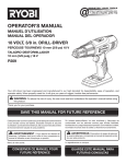


![DSK-RU取扱説明書[PDF:284.3KB]](http://vs1.manualzilla.com/store/data/006719731_2-462af4c07af156ead6efd2bff0fcf412-150x150.png)