1
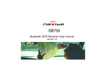
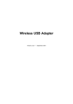
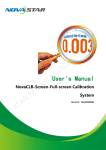
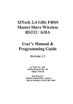
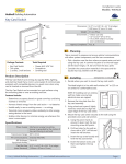
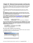
User’s Guide for 3G/GPS Camera Version: 1.2 Date: October 26, 2010 3G/GPS Camera User’s Guide Revision History Version Date Changes 1.0 06/29/2010 First Release of 3G/GPS Camera User’s Guide 1.1 10/14/2010 Update the function description upon ver.1.2.8.0 1.2 10/26/2010 Revise the positions of Volume+ and Volume- buttons Table of Contents Revision History -------------------------------------------------------- 2 TABLE OF CONTENTS ---------------------------------------------------- 2 CHATPER 1. PRODUCT OVERVIEW ------------------------------------------ 4 1.1 INTRODUCTION ------------------------------------------------------ 4 1.2 FEATURES --------------------------------------------------------- 5 1.3 PACKAGE CONTENTS -------------------------------------------------- 5 CHATPER 2. PHYSICAL DESCRIPTION---------------------------------------- 6 2.1 PANELS ----------------------------------------------------------- 6 2.1.1 Right Panel ---------------------------------------------------- 6 2.1.2 Left Panel ----------------------------------------------------- 7 2.2 ILLUSTRATION ------------------------------------------------------ 8 2.2.1 Right Panel Information ------------------------------------------- 9 3G ANT SMA Connector --------------------------------------------- 9 Volume + Button --------------------------------------------------- 9 Volume - Button --------------------------------------------------- 9 Push To Link Button ------------------------------------------------ 9 Record Button ----------------------------------------------------- 9 Key Lock Button --------------------------------------------------- 9 SD Card Slot ------------------------------------------------------ 9 LEDs ------------------------------------------------------------ 9 External GPS Antenna Connector -------------------------------------- 9 2.2.2 Left Panel Information -------------------------------------------- 9 SIM Card Slot ----------------------------------------------------- 9 Mini USB Video & Audio Connector------------------------------------- 9 Micro USB Power Supply Connector ------------------------------------ 9 2.2.3 LED Description on 3G/GPS Camera -------------------------------- 10 CHATPER 3. INSTALLING SOFTWARE--------------------------------------- 12 2 3G/GPS Camera User’s Guide 3.1 REGISTRATION OF 3G/GPS CAMERA -------------------------------------3.1.1 Changes of 3G/GPS Camera Basic Settings --------------------------3.1.2 Dialup Connection Setup ----------------------------------------3.2 VIEWING IMAGE FROM THE CAMERA --------------------------------------3.3 VOIP FOR FULL- DUPLEX VOICE COMMUNICATION ----------------------------3.3.1 REMOTE AUDIO/VIDEO RECORDING -----------------------------------3.3.2 DELETE CAMERAS -----------------------------------------------3.4 MAP SEARCHING THROUGH GPS ----------------------------------------3.4.1 GPS Data History Track------------------------------------------ 13 13 16 17 19 20 21 22 24 CHATPER 4. VIDEO/AUDIO CONTROL BY PUSH BUTTON SETUP------------------ 25 4.1 PUSH BUTTON SETUP ------------------------------------------------ 25 APPENDIX A RUNNING 3G/GPS CAMERA AP UNDER A ROUTER------------------- 26 3 3G/GPS Camera User’s Guide 1. Product Overview 1.1 Introduction 3G/GPS Camera, a 3G mobile camera, is enhanced the functions of full-duplex VoIP and GPS (Global Positioning System). Through these enhancements of this device, many field workers such as polices, fire fighters, security guards, rescue teams, field inspectors and construction workers not only can have a video and/or audio communication with the persons at the remote site but the current 3G/GPS Camera position located by the built-in GPS will be sent back upon the pre-set time interval. Besides the image, the SD memory card inserted onto 3G/GPS Camera also can support the savings of these GPS data. 4 3G/GPS Camera User’s Guide 1.2 Features With the built-in VoIP and GPS functions. Support the conference call function through the application software. Offer a “Record” functional button for the live video and audio recording. Offer a “Push to Link” functional button for the live video and/or audio connection with the remote central site. Offer a “Key Lock Button” functional button for Internet connection in a manual way. Provide the SD card for the storage of the live image and voice as well as GPS data. Offer the application software for the remote video/audio control. Remotely live recordings of the voice and/or image via the application software. 1.3 Package Contents ─ 1x 3G/GPS Camera ─ 1x 3G Antenna ─ 1x External GPS Antenna (Optional) ─ 1x 12V/1A Adapter with Micro USB Connector ─ 1x Mini USB Interface AV Cable with the Headset and Camera ─ 1x 2G SD Card ─ 1x CD with Demo Application Program and this 3G/GPS Camera User’s Guide ─ Quick Installation Guide 5 3G/GPS Camera User’s Guide 2. Physical Description The following information contains the physical description of 3G/GPS Camera. This includes the functions and the locations of each connector and indicator. This information provides useful reference when installing the product. Please familiarize yourself with 3G/GPS Camera. 2.1 Panels 2.1.1 Right Panel For more related description, please refer to the Section 2.2 and Section 2.2.1. 1 2 3 4 5 8 9 7 6 Fig. 1 View from the Right Side of 3G/GPS Camera 6 3G/GPS Camera User’s Guide 2.1.2 Left Panel For more detailed description, please refer to the Section 2.2 and Section 2.2.2. 12 11 10 Fig. 2 View from the Left Side of 3G/GPS Camera 7 3G/GPS Camera User’s Guide 2.2 Illustration No. in Figures Name on 3G/GPS Camera Description Remark 1 3G ANT SMA Connector To connect with the 3G/3.5G antenna Refer to section 2.2.1 for the right panel information 2 Volume + Button To amplify the volume of voice from the speaker Refer to section 2.2.1 for the right panel information 3 Volume - Button To lower the volume of voice from the speaker Refer to section 2.2.1 for the right panel information 4 Push To Link Button The control button for powering on/off 3G/GPS Camera and Refer to section 2.2.1 for the enabling/disabling the remote right panel information transmission of the live image/voice 5 Record Button To enable/disable the recording Refer to section 2.2.1 for the function of 3G/GPS Camera right panel information 6 Key Lock Button To enable/disable the access of Refer to section 2.2.1 for the Internet manually for 3G/GPS right panel information Camera 7 SD Card Slot To plug the SD card chip Refer to section 2.2.1 for the right panel information 8 LEDs To display the status of 3G/GPS Camera Refer to section 2.2.3 for LED description on 3G/GPS Camera 9 External GPS Antenna Connector To connect with the optional GPS Active Antenna externally Refer to section 2.2.1 for the right panel information 10 SIM Card Slot To plug the SIM card chip Refer to section 2.2.2 for the left panel information 11 Mini USB Video & Audio Connector To connect to an AV cable with the headset and camera Refer to section 2.2.2 for the left panel information 12 Micro USB Power Supply Connector Refer to section 2.2.2 for the To connect with the 3G/GPS Camera and the power adapter left panel information Table 2-1 8 3G/GPS Camera User’s Guide 2.2.1 Right Panel Information 3G ANT SMA Connector Support 3G mode for wireless access. Volume + Button Offer 0~7 stages in increasing the SPK strength. (Default: 3rd stage) Volume - Button Offer 0~7 stages in decreasing the SPK strength. (Default: 3rd stage) Push To Link Button Press this button will turn on the deactivated 3G/GPS Camera, and press this button will initiate the transmission of the live image and voice from 3G/GPS Camera to the remote site while 3G/GPS Camera is powered on. Keep pressing on this button over 3 seconds, the activated 3G/GPS Camera will be turned off. Record Button Press this button will have the live image and voice to be directly saved into the SD card installed on 3G/GPS Camera. Default Image size is 720 x 480. Key Lock Button Press this button will have 3G/GPS Camera get online if you choose the “Manual” as the online mode for your 3G/GPS Camera. And it will also disconnect the cellular connection with Internet by the press of this button when 3G/GPS Camera is at the on-line status. For more details about the online mode selection, please refer to Section 3.1.1.2. SD Card Slot Refer to the figure 1 for the correct direction of the SD card in installation. LEDs Include the LED of GPS, SD card status, system operation status, recording status, cellular signal strength and modems. External GPS Antenna Connector Strengthen the GPS signal when the built-in GPS fails to be searched in the outdoor use. 2.2.2 Left Panel Information SIM Card Slot To connect with the internal modem. Refer to the figure 2 for the correct direction of the SIM card in installation. Mini USB Video & Audio Connector Offer the camera and headset interface. Micro USB Power Supply Connector Plug the power adapter. The specifications of 3G/GPS Camera’s power adapter are as follows: Input: 100 ~ 240V AC, 50/60Hz Output: 12V DC / 1A 9 3G/GPS Camera User’s Guide 2.2.3 LED Description on 3G/GPS Camera Fig. 3 LEDs on 3G/GPS Camera LED Color 3G Modem LED Green Status Flash when the data is transmitting in 3G networks. Lit when no data is transmitting in 3G networks. Flash along with 3G modem LED when the data is transmitting in 2G networks. 2G Modem LED Red Lit along with 3G modem LED when no data is transmitting in 2G networks. Lit signally when the error (such as no detection of the SIM card or network failure) occurs. GPS LED Green Flash when GPS location is detected. Lit when no GPS location is detected. SD Card Status LED Red Lit when no space of the SD card is left. Off when the space of the SD card still remains. Recording Status LED Red Lit when the device is doing recording. Off when the device stops recording. Cellular Signal Strength LED Green Lit when the signal strength is good. Flash when the signal strength is moderate. Off when the signal strength is weak. 10 3G/GPS Camera User’s Guide Flash per second when the device is turned on in case the power supply from the adapter exists. Lit when the device is being charged in case the power supply from the adapter exists. System Operation Status LED Green Off when the device is fully charged in case the power supply from the adapter exists. Flash per second when the device is turned on in case the power supply from the battery exists. Off when the device is turned off in case the power supply from the battery exists. Table 2-2 11 3G/GPS Camera User’s Guide 3. Installing Software Installing the software is very simple. Double click the 3G_Camera_and_Audio.msi file and simply follow the instruction provided by the installation wizard and the installation should be completed. The steps are as follows: Please select Next when you have see the following screen. At the next window, click the Browse… button to select your desired directory in case you would like to install the 3G_Camera_and_Audio AP in different pathway. Select Next when done. Click Next to initiate the installation. 12 3G/GPS Camera User’s Guide Click Close when the installation is complete. Once the installation is complete, you can start the program from your Start Menu or the shortcut on the Desktop. 3.1 Registration of 3G/GPS Camera 3G_Camera_and_Audio AP supports multiple 3G/GPS Cameras. Only through the modification of the basic settings stored in the SD card of your 3G/GPS Cameras will have them register to your PC/server running 3G_Camera_and_Audio AP easily. 3.1.1 Changes of 3G/GPS Camera Basic Settings For the parameter settings of your 3G/GPS Camera registration, please unplug the SD card from your 3G/GPS Camera and insert it into your removable storage device connected to your PC/server when 3G_Camera_and_Audio AP is initiated. Select Option from the file menu and execute the 3G Camera and Audio_SD…function, the 3G/GPS Camera registration setup would be completed by following the setup wizard step by step. 13 3G/GPS Camera User’s Guide In the Step 1 setting page, you will find the drive letter list showing all drives detected by 3G_Camera_and_Audio AP automatically. Select the letter standing for the drive in which your SD card is located from this pull-down drive list. Also select 3G/GPRS item as the network connection way for your 3G/GPS Camera. Click Next when completing. 3G/GPS Camera’s original settings, including the public IP address of your PC/server or gateway (if your PC is using the virtual IP address) at the remote site, local port No., device name, the NTSC/PAL setting used for your camera video input, interval of GPS data sending, the password belonging to 3G/GPS Camera, the time zone setup, and the setup of recording mode as well as online mode (For more details on the settings of these two modes, please refer to the next 3.1.1.1 and 3.1.1.2 sections) will be loaded if you had ever set up 3G/GPS Camera when entering the Step 2 setting page. Otherwise, the default value will be shown on this setting page in your first use of 3G/GPS Camera. In filling in your new settings, you can click on the Public IP of PC button to get the public IP address of your PC/server or gateway automatically if you would like this IP address as the remote IP. In addition, 3G/GPS Camera also provides a Load Default button for users to reset these parameters to the factory default. Click on the Next button when you complete to continue the dialup connection setup that we will describe in Section 3.1.2. Or click on the Previous button to go back to the last setting page. 3.1.1.1 Spot Recording Mode Selection For the live image recordings at the local site, there are two modes, including “automatic” and “manual” offered for 3G/GPS Camera. In the former mode, it will automatically start to do the recordings while 3G/GPS Camera is powered on. Or else the recordings will be initialized only when you press the Record button on 3G/GPS Camera in the latter mode. For the correct position of this button, please refer to Section 2.1.1 and Section 2.2. To disable this recording, please press this button whatever the “automatic” or “manual” mode is chosen. 14 3G/GPS Camera User’s Guide 3.1.1.2 Online Mode Selection For the connection with Internet via 3G/GPRS, there are also two modes, including “automatic” and “manual” offered for 3G/GPS Camera. It will automatically start the dialup to connect to Internet in the former mode while 3G/GPS Camera is powered on. As to the latter mode, the cellular connection will be initialized only when you press the Key Lock button on 3G/GPS Camera. For the correct position of this button, please refer to Section 2.1.1 and Section 2.2. To disable this network connection, please press this button whatever the “automatic” or “manual” mode is chosen. 15 3G/GPS Camera User’s Guide 3.1.2 Dialup Connection Setup Before starting the SIM Internet setup in the Step 3 setting page, you must request your Internet service provider (ISP) to provide you with the values to fill in the following required fields, including the username, password, GPRS dial command and access point name (APN Gateway) of the SIM card for 3G/GPS Camera’s Internet connection. As to the setup of the Connect Mode parameter, please choose the proper network connection way for your 3G/GPS Camera between 3G/2.5G and GPRS upon the SIM card you use. To return to the factory default value, please click on the Load Default button. To save all new settings from Step1 to Step3, please click on the Setup Completes button. The original settings will be replaced immediately. Click on the OK button to exit 3G/GPS Camera SD settings and remove the SD card from your removable storage device. Before inserting this SD card into the SD card slot of 3G/GPS Camera, it is recommended that you had better power off 3G/GPS Camera in advance. (For the correct installation of the SD card, please refer to the figure 1 in Section 2.) 3G/GPS Camera will be registered automatically to the assigned PC/server running 3G_Camera_and_Audio AP upon the given remote IP when it is powered on. The entry of your 3G/GPS Camera information will also appear on the camera list of 3G_Camera_and_Audio AP. Note: A 3G/GPS Camera can only accept the request of registration from a PC/server within a period of time. An on-line 3G/GPS Camera will fail to register to another PC/server. 16 3G/GPS Camera User’s Guide 3.2 Viewing Image from the Camera Before the viewings of your cameras, please make sure that the IP address of your PC/server used to run the 3G_Camera_and_Audio AP is public IP. You may refer to Appendix A if you would like to run the 3G_Camera_and_Audio AP under a router with the virtual server or port forwarding setting. To view the image from the 3G/GPS Camera through 3G_Camera_and_Audio AP, just click on the checkbox in front of the ID belonging to your desired 3G/GPS Camera on the camera list, and an image window will be pop up at the section below the camera list. The live Image will be shown on this window after the countdown (see the figure below). And clicking on the checkbox of the 3G/GPS Camera again will stop displaying the image. 3G_Camera_and_Audio AP also supports 2 different viewing sizes, including QVGA (320x240) and VGA (640x480). To switch between these image sizes, simply right click on the image and you will be able to change your desired image size by selecting the function of ImageSize from the pop-up menu. You may also decide to record the image you are viewing on PC/server running 3G_Camera_and_Audio AP or not. The system will start to record the image upon your current image size setting of the image if the Save function from this pop-up menu is enabled. To disable the recording of image, simply right click on the image again and select the Stop Save function from the pop-up menu. 3G_Camera_and_Audio AP will automatically detect the current recording status and switch the Save/Stop Save function accordingly. You are also allowed to take a picture of the camera image while you are browsing if necessary. Simply double click on the desired image window, then the snapshot will easily take an instant image upon your current image size setting of the image. All of the picture files (*.jpg) will be placed at the folder which is automatically created and named by the camera ID of your 3G/GPS Camera under the directory you had installed 3G_Camera_and_Audio AP (Default record path is C:\Program Files\3G_Camera_and_Audio\). Each filename of the picture is based on the system time of your PC when you run the snapshot. Its format is year, month, day, hour, minute, and second. 17 3G/GPS Camera User’s Guide Additionally, you will have the video recording function to be initiated as well by right clicking the entry of 3G/GPS Camera you are browsing on the camera list and then selecting Record / Video / Start from the extendable menu appeared. In case this video recording is completed or you would like to cancel it, merely do the right clicking on this entry of 3G/GPS Camera again and select Record / Video / Stop from the menu appeared. The system will stop recording. All of the image recording files (*.avi) will be placed at the folder which is automatically created and named by the camera ID of your 3G/GPS Camera under the directory you had installed 3G_Camera_and_Audio AP (Default record path is C:\Program Files\3G_Camera_and_Audio\). In multiple 3G/GPS Cameras viewings, 3G_Camera_and_Audio AP provides 2 different viewing options for the user to select from; Vertical Mode and Horizontal Mode. You can change the image arrangement for multiple 3G/GPS Cameras vertically or horizontally. To choose between these two viewing types, please select Windows from the file menu to decide the vertical mode or the horizontal mode. The setting will be taken effect immediately. NOTE: On the camera list, the entry of the 3G/GPS Camera in black color stands that this device has been registered normally. The one in red color stands that the device is off-line. 18 3G/GPS Camera User’s Guide 3.3 VoIP for Full- Duplex Voice Communication In addition to 3G/GPS Camera proprietary protocol, 3G/GPS Camera also supports SIP (Session Initiation Protocol) technology in its voice communication function. To do the full-duplex communication via the 3G_Camera_and_Audio AP is very easy. Just select the desired 3G/GPS Camera on the camera list and right click on the entry belonging to this selected camera. Please choose the Dial function from the pop-up menu, and you will begin to talk with the persons at the local site when the dialing succeeds. At this time, the information shown in the field of Audio Status will be transferred from “Available” into “The Line Is Busy”. 3G_Camera_and_Audio AP will automatically detect the current talking mode and switch the function on the pop-up menu accordingly. To stop the communication, just click on the Hang up function from this menu. Or click on the Answer function in reply to the incoming call from the selected 3G/GPS Camera. For more details about making a voice call from 3G/GPS Camera, please refer to the next chapter of “Video/Audio Control by Push Button Setup”. Note: On the entry of 3G/GPS Camera, there will be four kinds of different information displayed in the field of “Audio Status” upon the calling status. See the following table for the detailed information. Audio Status Description Available It stands that no calling is made or no incoming call exists currently. Dialing…x It stands that the dialing is in progress. Calls incoming The line is busy It stands that there is an incoming call calling from 3G/GPS Camera by the press of its “Push To Link” button. It stands that the dialing is successful and get ready to have a conversation between the remote site and the local site. To increase the quality of voice, you may click on the checkbox in front of Echo/Noise Cancellation to lower the disturbance of echo and noise. You can also use the volume control bar on 3G_Camera_and_Audio AP to adjust the volume of the speaker and the microphone connected to PC/server. Or click on the checkbox in front of Mute will have your speaker or microphone keep silent. 19 3G/GPS Camera User’s Guide In the VoIP application, 3G_Camera_and_Audio AP also supports the conference call function. With the usage of this function, you will be able to talk with the maximum of eight 3G/GPS Cameras concurrently. Please note that two or above 3G/GPS Cameras you would like to do the conference call on the camera list MUST be at the” The Line Is Busy” audio status in advance of clicking on the checkbox in front of Start Conference to enable the conference call function. Persons at these multiple sites will then be allowed to have the communication with each other through 3G_Camera_and_Audio AP. 3.3.1 Remote Audio/Video Recording Besides the video recording we had mentioned in the previous section, 3G_Camera_and_Audio AP also supports the audio recording between the local site and the remote site. Simply right click on the entry of 3G/GPS Camera having the communication in progress, and the voice recording function will be activated when choosing Record / Audio / Start from the extendable menu appeared. To end up this voice recording, also right click on this entry of 3G/GPS Camera again and select Record / Audio / Stop from the extendable menu appeared. Likewise, if you would like to do the both video and audio recording at the same time while you are viewing image and having a voice communication via the 3G_Camera_and_Audio AP, please select Record / Both Video and Audio / Start or Record / Both Video and Audio / Stop from the extendable menu appeared to activate/deactivate this recording function respectively. The system also will save these voice recording files(*.wav) or voice & image recording files (*.avi) in the same folder which is automatically created and named by the camera ID of your 3G/GPS Camera under the directory you had installed 3G_Camera_and_Audio AP (Default record path is C:\Program Files\3G_Camera_and_Audio\). 20 3G/GPS Camera User’s Guide 3.3.2 Delete Cameras Deletion of any off-line 3G/GPS Cameras that had ever been registered from the camera list is simple. Simply select the camera you wish to delete, and choose the function of Delete from the pop-up menu by right clicking on the entry belonging to this selected camera. Please click OK to confirm camera deletion. The selected camera would be removed immediately. It is useful when you have many registered 3G/GPS Cameras which would be unused temporarily. 21 3G/GPS Camera User’s Guide 3.4 MAP Searching through GPS As we had mentioned above, the GPS data from 3G/GPS Camera will be sent back to the remote site running 3G_Camera_and_Audio AP upon your pre-set time interval. Based on these data, you can find the position of your 3G/GPS Cameras with precision on the map. Before initiating the GPS MAP function of 3G_Camera_and_Audio AP in search of your 3G/GPS Cameras’ position, you should select MAP… from the file menu and choose the Setup MAP function in advance to open the GpsSystem.exe file located in the directory you had installed our GPS AP (Default installation path is C:\Program Files\3G_Camera_and_Audio\3G_Camera_and_Audio\GpsSystem\). Then, you will see the Run MAP function under the MAP… file menu is enabled. Execute this function, and the GPS function will begin to search for the position of all 3G/GPS Cameras currently registered to your PC running 3G_Camera_and_Audio AP when receiving the correct GPS data. If 3G/GPS Cameras are located successfully, they will be symbolized by a red drop on the GPS living map respectively (see the figure below). To move to other GPS points of 3G/GPS Cameras, please use the direction or zoom in/out tools provided on the map. 22 3G/GPS Camera User’s Guide Besides the map, you also can see the detailed GPS position data, including camera ID, camera name, time, status, direction, velocity (knots), velocity (KPH), latitude and longitude of each 3G/GPS Cameras on the camera list located below the GPS living map. From the color of the entries, you can realize the status of GPS data transmission for your 3G/GPS Cameras. Note: The entry of the 3G/GPS Camera in GREEN color stands that the current GPS data from this camera is correct. In case the current GPS data from 3G/GPS Camera is incorrect or no GPS data is received in 3 minutes, the color of the entry will become RED or BLUE color respectively. 23 3G/GPS Camera User’s Guide 3.4.1 GPS Data History Track Clicking on the History track button, and you will see 3G/GPS Cameras that has been registered to 3G_Camera_and_Audio AP listed in tree structure on the top-right section. To track the GPS history among these registered 3G/GPS Cameras, the user must set up the parameters, including the desired range of date (yyyy/mm/dd) by pulling down the calendar list and 3G/GPS Camera ID for the search. When inputting the 3G/GPS Camera ID, you may fill it in manually or right click on the desired 3G/GPS Camera ID from the tree-structured list to add it automatically by choosing History Track function from the pop-up menu (see the figure below). The GPS system will soon provide the map containing the history track in red line upon the given condition when clicking on the Search button. 24 3G/GPS Camera User’s Guide 4. Video/Audio Control by Push Button Setup The press of the Push to Link button while 3G/GPS Camera is powering on will allow the image and/or voice on the spot to be remotely transmitted to PC/server running 3G_Camera_and_Audio AP at any time. For its correct position, please refer to the Section 2.1.1 and Section 2.2. 4.1 Push Button Setup Through the 3G_Camera_and_Audio AP, the user at remote site can decide the status of video or audio input from 3G/GPS Camera. To control the ON/OFF of video or audio from 3G/GPS Camera, please select Option from the file menu and choose the Push function. Button Setup In this function, it can be divided into Open and Close two parts. The former contains Audio as well as Both Video and Audio options, and the latter contains Audio as well as Ignore options for the user’s selection respectively. For controlling the display of image and voice from 3G/GPS Camera correctly, you may refer to the parameter description listed below. Open / Audio : Allow the voice from 3G/GPS Camera to be transmitted and heard at the remote site. Open / Both Video and Audio : The user at the remote site will not only see the image from 3G/GPS Camera on the PC/server running 3G_Camera_and_Audio AP but hear the voice from it at the same time. Close / Audio : Forbid the voice from 3G/GPS Camera to be transmitted and heard at the remote site. Close / Ignore : Any request of Push To Link from 3G/GPS Camera to close the video or audio will be ignored and have no effect on the remote site. 25 3G/GPS Camera User’s Guide Appendix A Running 3G/GPS Camera AP under A Router It is strongly recommended that you can set up the DMZ function of the router if you would like to execute the audio and video transmission under a router. By assigning the IP address of your PC running the 3G/GPS Camera AP, you will be allowed to view the image from the camera and have the voice communication with the local site through the 3G/GPS Camera AP. The function of virtual server / port forwarding is the alternative solution if the DMZ function is not built in your router. Before doing one of these settings, please refer to your router user’s manual to enter its setting webpage. In the following example, we take 3JTech wifiSwitch_USB router to demonstrate the virtual server setup, and procedures listed below may differ in case you use other brand routers. 1) Find the Virtual Server function in your router. 2) Click on the checkbox in front of Enable to have the virtual server function enabled. 3) For the image transmission, you need to customize a TCP virtual server. Please assign a meaningful name to a new virtual server, fill in the IP address of your PC running the 3G/GPS Camera AP, select TCP as the protocol type, and assign a desired port No. (Valid port range: 11433 ~ 11438) as the private port and the public port for 3G/GPS Camera accordingly. 4) Repeat the procedures in Step 3 to create the necessary virtual servers upon your demands. 5) Click on the Save button when completing. 6) For 3G/GPS Camera’s registration, a UDP virtual server needs to be customized. Please assign a meaningful name to a new virtual server, fill in the IP address of your PC running the 3G/GPS Camera AP, select UDP as the protocol type, and assign 9112 as the private port and the public port for 3G/GPS Camera accordingly. 7) Click on the Save button when completing. 8) For the communication with the SIP protocol, you need to customize a both TCP and UDP virtual server. Please assign a meaningful name to a new virtual server, fill in the IP address of your PC running the 3G/GPS Camera AP, select Both as the protocol type, and assign 5060 as the private port and the public port for 3G/GPS Camera accordingly. 9) Click on the Save button when completing. 10) A both TCP and UDP virtual server needs to be customized for the voice transmission as well. Please assign a meaningful name to a new virtual server, fill in the IP address of your PC running the 3G/GPS Camera AP, select Both as the protocol type, and assign a desired port No. (Valid port range: 7000 ~ 7010) as the private port and the public port for 3G/GPS Camera accordingly. 26 3G/GPS Camera User’s Guide 11) Repeat the procedures in Step 10 to create the necessary virtual servers upon your demands. 12) Click on the Save button when completing. 13) All of the virtual servers you had created will be listed on the virtual servers list (see the figure below). As to the port forwarding function, here, we take 3JTech DWR (Dedicated WIFI Router) for example to describe how to do this setting, and procedures listed below may differ in case you use other brand router. 1) Find the Port Forwarding function in your router. 2) Click on the checkbox in front of Enable Port Forwarding to have the port forwarding function enabled. 3) To create a TCP forwarding port for the image transmission, please fill in the IP address of your PC running the 3G/GPS Camera AP, select TCP as Type, and assign port range as 11433-11438 for 3G/GPS Camera. 4) Click on the Apply Changes button when completing. 5) To create a UDP forwarding port for 3G/GPS Camera’s registration, please also fill in the IP address of your PC running the 3G/GPS Camera AP, select UDP as Type, and assign port range as 9112- 9112 for 3G/GPS Camera. 6) Click on the Apply Changes button when completing. 7) For the communication with the SIP protocol, you need to create a both TCP and UDP forwarding port. Please fill in the IP address of your PC running the 3G/GPS Camera AP, select Both as Type, and assign port range as 5060- 5060 for 3G/GPS Camera. 27 3G/GPS Camera User’s Guide 8) Click on the Apply Changes button when completing. 9) For the voice transmission, you also need to create a both TCP and UDP forwarding port. Please fill in the IP address of your PC running the 3G/GPS Camera AP, select Both as Type, and assign port range as 7000- 7010 for 3G/GPS Camera. 10) Click on the Apply Changes button when completing. 11) All of the forwarding ports you had created will be listed on the port forwarding table (see the figure below). 28